EP3899290B1 - Befestigungselement - Google Patents
Befestigungselement Download PDFInfo
- Publication number
- EP3899290B1 EP3899290B1 EP19816616.7A EP19816616A EP3899290B1 EP 3899290 B1 EP3899290 B1 EP 3899290B1 EP 19816616 A EP19816616 A EP 19816616A EP 3899290 B1 EP3899290 B1 EP 3899290B1
- Authority
- EP
- European Patent Office
- Prior art keywords
- shank
- tip
- fastening element
- area
- cross
- Prior art date
- Legal status (The legal status is an assumption and is not a legal conclusion. Google has not performed a legal analysis and makes no representation as to the accuracy of the status listed.)
- Active
Links
Images


Classifications
-
- F—MECHANICAL ENGINEERING; LIGHTING; HEATING; WEAPONS; BLASTING
- F16—ENGINEERING ELEMENTS AND UNITS; GENERAL MEASURES FOR PRODUCING AND MAINTAINING EFFECTIVE FUNCTIONING OF MACHINES OR INSTALLATIONS; THERMAL INSULATION IN GENERAL
- F16B—DEVICES FOR FASTENING OR SECURING CONSTRUCTIONAL ELEMENTS OR MACHINE PARTS TOGETHER, e.g. NAILS, BOLTS, CIRCLIPS, CLAMPS, CLIPS OR WEDGES; JOINTS OR JOINTING
- F16B15/00—Nails; Staples
- F16B15/06—Nails; Staples with barbs, e.g. for metal parts; Drive screws
-
- F—MECHANICAL ENGINEERING; LIGHTING; HEATING; WEAPONS; BLASTING
- F16—ENGINEERING ELEMENTS AND UNITS; GENERAL MEASURES FOR PRODUCING AND MAINTAINING EFFECTIVE FUNCTIONING OF MACHINES OR INSTALLATIONS; THERMAL INSULATION IN GENERAL
- F16B—DEVICES FOR FASTENING OR SECURING CONSTRUCTIONAL ELEMENTS OR MACHINE PARTS TOGETHER, e.g. NAILS, BOLTS, CIRCLIPS, CLAMPS, CLIPS OR WEDGES; JOINTS OR JOINTING
- F16B19/00—Bolts without screw-thread; Pins, including deformable elements; Rivets
- F16B19/14—Bolts or the like for shooting into concrete constructions, metal walls or the like by means of detonation-operated nailing tools
Definitions
- the present invention relates to a fastener such as a bolt, nail or pin.
- Fastening elements of this type such as nails, bolts and the like made of steel, are used in fastening technology for fastening objects to hard receiving materials such as concrete, metal or rock.
- the fastening elements have a shank, in particular with a tip that tapers in the setting direction and a head that is located at the other end of the shank and is larger than the diameter of the shank.
- the driving-in process takes place at high speed in a percussive or driving-in manner, for example using combustion-powered setting tools.
- Fastening elements are known in which the shank has a profile on its circumference with a plurality of profile ridges and furrows in between. Furthermore, configurations are known in which the profile backs are inclined to the direction of attachment.
- a fastener having a shank and a tip is known.
- the shank has a first crowned section and a second section, which adjoins the first crowned section. Furthermore, a thread profile is arranged on the shank.
- An object of the present invention is to provide a fastener with high fastening strength.
- a fastener according to the invention has the features of claim 1.
- the profile back has a front flank pointing in the fastening direction and a rear flank pointing counter to the fastening direction, the front flank having a larger surface area than the rear flank.
- the fastening element comprises a tip area adjoining the front end of the shank with a nail tip, the tip area having a tip length measured in the driving direction and a cross-sectional area oriented perpendicularly to the driving direction with a surface area which at a transition from the tip area to the shank is as large as the surface area of the cross-sectional area of the shank and decreases from the shank to the nail tip, and wherein the tip region comprises a crowned portion.
- the tip area preferably consists of the crowned section. Due to the crowned shape of the tip portion, the area of the cross-sectional area of the tip portion increases rapidly from the tip of the nail, so that much frictional heat is generated at the beginning of a driving operation. As a result, a surface of the profile back can make a greater contribution to a holding force of the fastening element in the substrate, so that the fastening force of the fastening element is increased.
- the tip area has a tip area center which is equidistant from the transition from the tip area to the shank and from the nail tip measured in the driving direction, and wherein the surface area of the cross-sectional area of the tip area at the tip area center is more than 25 % of the area of the cross-sectional area of the shank.
- the surface area of the cross-sectional area of the tip region at the center of the tip region is more than 50%, particularly preferably more than 70% or more than 75% of the surface area of the cross-sectional area of the shank.
- An advantageous embodiment is characterized in that the shank has a shank diameter measured in the area of the rear of the profile, and the tip length is 1.1 to 1.6 times the shank diameter.
- the angle of inclination of the profile back relative to the driving direction is less than 20°.
- An advantageous embodiment is characterized in that a cross-sectional area of the shank has a surface area which does not change significantly along the driving direction.
- fastening element comprises a head adjoining the rear end of the shank.
- the shaft has two or at least three, preferably at least four profile backs.
- the backs of the profile are particularly preferably distributed evenly around the circumference of the upper.
- the tip region has a cross-sectional area whose surface area steadily decreases from the shank to the tip of the nail.
- the back of the profile preferably continues from the shaft into the tip area. Particularly preferably, the back of the profile continues essentially to the tip of the nail.
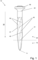
- the 1 and 2 show a fastener 10 in a side view.
- the fastening element 10 comprises a shank 20 which defines a driving-in direction 30 and has a front end 21 pointing in the driving-in direction 30 and a rear end 22 pointing counter to the driving-in direction 30 .
- the shank 20 has a cross-sectional area oriented perpendicularly to the driving-in direction 30 and on its circumference a plurality of profile backs 40 inclined at an acute angle of 15° to the driving-in direction. In each case between two profile backs 40, intermediate profile regions 50 are formed, which in the present example are designed as furrows.
- a head 60 connects to the rear end 22 of the shaft 20 .
- the front end 21 of the shank 20 is adjoined by a convex tip area 70 with a preferably punctiform nail tip 71 .
- the profile backs 40 each have a front flank 41 pointing in the fastening direction 30 and a rear flank 42 pointing counter to the fastening direction 30 and continue from the shaft 20 into the tip region 70 up to the nail tip 71 .
- 3 12 shows a rolling die 80 which can be used to produce the fastening element by rolling a blank (not shown) with a shank between the rolling die 80 and a counter-jaw of the same shape in a rolling direction 85.
- the rolling die 80 has a plurality of grooves 90 so that during rolling a profile with a profile back is rolled into a circumference of the shank.
- the grooves 90 are inclined at an acute angle ⁇ relative to a longitudinal direction of the shank, which is oriented perpendicularly to the rolling direction 85, so that the rolled profile backs are also inclined by the angle ⁇ relative to the longitudinal direction of the shank.
- the rolling die 80 and the counter-jaw have areas which lie opposite one another during rolling.
- a gap occurring between the said areas narrows in a direction pointing away from the grooves 90, so that a material of the tip area is squeezed between the roller die 80 and the counter-jaw.
- the tip area is shaped on the one hand and heated on the other hand, so that excess material can simply be thermally separated from the tip area of the fastening element should extend to the nail tip, a thermal pulling apart of two nail blanks is preferred EP 1 057 553 B1 for application.
- the grooves of the roller die and/or the counter-jaw extend into the tapering gap mentioned above.
- FIG. 12 shows a cross-sectional area 100 of a shank 120 of a fastening element, oriented perpendicular to the driving direction, according to several different exemplary embodiments.
- the respective shank 120 has four profile backs 140 distributed evenly around the circumference of the respective shank 120 and intermediate profile regions 150 in between, which in the case of the in 4 are formed as furrows in the exemplary embodiments illustrated on the left and in the middle.
- the intermediate profile areas 150 are flat; in the exemplary embodiments that are not shown, the intermediate profile areas are concave.
- the profile backs are characterized in that they project radially in relation to a circular cross-sectional shape and in relation to the intermediate profile areas.
- the respective shank 120 has a shank diameter d measured in the area of the profile back.
- each profile back 140 Due to the inclination of the profile back 140 relative to the driving direction, each profile back 140 has a front flank 141 pointing in the fastening direction and a rear flank 142 pointing against the fastening direction, with the front flank 141 being heated more during a driving-in process by friction than the rear flank 142.
- the front flank 141 has a larger surface area than the rear flank 142, so that overall a fastening force of the fastening element is increased.
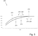
- figure 5 shows in a diagram 200 a profile of a surface area of a cross-sectional area of a fastening element in two exemplary embodiments, plotted as a percentage of a surface area in the area of a shank 220 of the fastening element against a distance to a nail tip in millimeters.
- the surface area does not change significantly (100%) along the driving direction.
- the surface area steadily decreases, starting from 100% at a transition 272 from the tip region 270 to the shank 220, down to a nail tip (0 mm, 0%).
- the tip region 270 has a tip region center 273 equidistant from the transition 272 and from the nail tip.
- the area of the cross-sectional area of the tip area 270 is 72% in the first embodiment (lower curve) and 78% in the second embodiment (upper curve) of the area of the cross-sectional area of the shaft 220. Furthermore, a seat length of the tip area from the transition 272 to to Naelsitz in the first embodiment (lower curve) 1.5 times, in the second embodiment (upper curve) 1.2 times the shank diameter.
Landscapes
- Engineering & Computer Science (AREA)
- General Engineering & Computer Science (AREA)
- Mechanical Engineering (AREA)
- Portable Nailing Machines And Staplers (AREA)
- Mutual Connection Of Rods And Tubes (AREA)
- Connection Of Plates (AREA)
- Insertion Pins And Rivets (AREA)
Description
- Die vorliegende Erfindung betrifft ein Befestigungselement, wie beispielsweise Bolzen, Nagel oder Stift.
- Derartige Befestigungselemente, wie z.B. Nägel, Bolzen und dgl. aus Stahl, werden in der Befestigungstechnik zum Befestigen von Gegenständen an harten Aufnahmewerkstoffen, wie Beton, Metall oder Gestein, eingesetzt. Die Befestigungselemente weisen dazu einen Schaft insbesondere mit einer sich in Setzrichtung verjüngenden Spitze und einem am anderen Ende des Schaftes liegenden Kopf auf, welcher gegenüber dem Durchmesser des Schaftes vergrössert ist. Der Eintreibvorgang erfolgt mit hoher Geschwindigkeit schlagend oder eintreibend beispielsweise mittels brennkraftbetriebener Setzgeräte.
- Es sind Befestigungselemente bekannt, bei denen der Schaft an seinem Umfang ein Profil mit mehreren Profilrücken und dazwischenliegenden Furchen aufweist. Weiterhin sind Gestaltungen bekannt, bei denen die Profilrücken zur Befestigungsrichtung geneigt sind.
- Aus der
DE 10 2004 040 701 B3 ist ein Befestigungselement mit einem Schaft und einer Spitze bekannt. Der Schaft weist einen ersten balligen Abschnitt und einen zweiten Abschnitt, der sich an den ersten balligen Abschnitt anschliesst, auf. Ferner ist an dem Schaft eine Gewindeprofilierung angeordnet. - Eine Aufgabe der vorliegenden Erfindung liegt darin, ein Befestigungselement mit hoher Befestigungskraft zur Verfügung zu stellen.
- Ein erfindungsgemäßes Befestigungselement weist die Merkmale von Anspruch 1 auf.
- Gemäss einem ersten Aspekt weist der Profilrücken eine in die Befestigungsrichtung weisende Vorderflanke und eine gegen die Befestigungsrichtung weisende Hinterflanke auf, wobei die Vorderflanke einen grösseren Flächeninhalt aufweist als die Hinterflanke. Dadurch wird diejenige Fläche des Profilrückens, welche während eines Eintreibvorgangs durch Reibung aufgeheizt wird und dadurch verstärkt zu einer Haltekraft des Befestigungselements in dem Untergrund beiträgt, auf Kosten von Flächen mit geringerem Beitrag zur Haltekraft vergrössert, so dass insgesamt die Befestigungskraft des Befestigungselements erhöht ist.
- Gemäss der Erfindung umfasst das Befestigungselement einen sich an das Vorderende des Schaftes anschliessenden Spitzenbereich mit einer Nagelspitze, wobei der Spitzenbereich eine in der Eintreibrichtung gemessene Spitzenlänge und eine senkrecht zur Eintreibrichtung orientierte Querschnittsfläche mit einem Flächeninhalt aufweist, welcher an einem Übergang von dem Spitzenbereich zum Schaft so gross ist wie der Flächeninhalt der Querschnittsfläche des Schaftes und sich von dem Schaft zur Nagelspitze verringert, und wobei der Spitzenbereich einen balligen Abschnitt umfasst. Bevorzugt besteht der Spitzenbereich aus dem balligen Abschnitt. Aufgrund der balligen Form des Spitzenbereichs steigt der Flächeninhalt der Querschnittsfläche des Spitzenbereichs ausgehend von der Nagelspitze schnell an, so dass zu Beginn eines Eintreibvorgangs viel Reibungswärme erzeugt wird. Dadurch kann eine Oberfläche des Profilrückens verstärkt zu einer Haltekraft des Befestigungselements in dem Untergrund beitragen, so dass die Befestigungskraft des Befestigungselements erhöht ist.
- Eine vorteilhafte Ausführungsform ist dadurch gekennzeichnet, dass der Spitzenbereich eine Spitzenbereichsmitte aufweist, welche von dem Übergang von dem Spitzenbereich zum Schaft und von der Nagelspitze in der Eintreibrichtung gemessen gleich weit entfernt ist, und wobei der Flächeninhalt der Querschnittsfläche des Spitzenbereichs an der Spitzenbereichsmitte mehr als 25% des Flächeninhalts der Querschnittsfläche des Schaftes beträgt. Bevorzugt beträgt der Flächeninhalt der Querschnittsfläche des Spitzenbereichs an der Spitzenbereichsmitte mehr als 50%, besonders bevorzugt mehr als 70% oder mehr als 75% des Flächeninhalts der Querschnittsfläche des Schaftes.
- Eine vorteilhafte Ausführungsform ist dadurch gekennzeichnet, dass der Schaft einen im Bereich des Profilrückens gemessenen Schaftdurchmesser aufweist, und wobei die Spitzenlänge das 1,1- bis 1,6-fache des Schaftdurchmessers beträgt.
- Gemäß der Erfindung beträgt ein Neigungswinkel des Profilrückens gegenüber der Eintreibrichtung weniger als 20°.
- Dadurch ist sichergestellt, dass ein Schlag auf das Befestigungselement in der Eintreibrichtung eine Drehung des Befestigungselements verursacht. Unter Umständen eignet sich der Profilrücken nicht als Gewinde, welches eine Drehung des Befestigungselements in einen Vortrieb umwandeln würde.
- Eine vorteilhafte Ausführungsform ist dadurch gekennzeichnet, dass eine Querschnittsfläche des Schaftes einen Flächeninhalt aufweist, welcher sich entlang der Eintreibrichtung nicht wesentlich ändert.
- Eine vorteilhafte Ausführungsform ist dadurch gekennzeichnet, dass das Befestigungselement einen sich an das Hinterende des Schaftes anschliessenden Kopf umfasst.
- Eine vorteilhafte Ausführungsform ist dadurch gekennzeichnet, dass der Schaft zwei oder mindestens drei, bevorzugt mindestens vier Profilrücken aufweist. Besonders bevorzugt sind die Profilrücken gleichmässig am Umfang des Schaftes verteilt.
- Gemäß der Erfindung weist der Spitzenbereich eine Querschnittsfläche auf, deren Flächeninhalt sich von dem Schaft zur Nagelspitze stetig verringert. Bevorzugt setzt sich der Profilrücken vom Schaft aus in den Spitzenbereich hinein fort. Besonders bevorzugt setzt sich der Profilrücken im Wesentlichen bis zur Nagelspitze fort.
- Weitere Vorteile und Massnahmen der Erfindung ergeben sich aus den Unteransprüchen, der nachfolgenden Beschreibung und den Zeichnungen. In den Zeichnungen ist die Erfindung in einem Ausführungsbeispiel dargestellt.
- Es zeigen:
- Fig. 1
- ein erfindungsgemässes Befestigungselement in Seitenansicht,
- Fig. 2
- das Befestigungselement in Schrägansicht,
- Fig. 3
- eine Walzbacke zur Herstellung des Befestigungselements,
- Fig. 4
- verschiedene Ausführungsbeispiele einer Querschnittsfläche eines Befestigungselements und
- Fig. 5
- einen Verlauf eines Flächeninhalts einer Querschnittsfläche eines Befestigungselements.
- Die
Fig. 1 und2 zeigen ein Befestigungselement 10 in einer Seitenansicht. Das Befestigungselement 10 umfasst einen Schaft 20, welcher eine Eintreibrichtung 30 definiert und ein in die Eintreibrichtung 30 weisendes Vorderende 21 sowie ein gegen die Eintreibrichtung 30 weisendes Hinterende 22 aufweist. Der Schaft 20 weist eine senkrecht zur Eintreibrichtung 30 orientierte Querschnittsfläche und an seinem Umfang mehrere zur Eintreibrichtung in einem spitzen Winkel von 15° geneigte Profilrücken 40 auf. Jeweils zwischen zwei Profilrücken 40 bilden sich Profilzwischenbereiche 50 aus, welche im vorliegenden Beispiel als Furchen ausgebildet sind. An das Hinterende 22 des Schaftes 20 schliesst sich ein Kopf 60 an. An das Vorderende 21 des Schaftes 20 schliesst sich ein balliger Spitzenbereich 70 mit einer bevorzugt punktförmigen Nagelspitze 71 an. Die Profilrücken 40 weisen jeweils eine in die Befestigungsrichtung 30 weisende Vorderflanke 41 und eine gegen die Befestigungsrichtung 30 weisende Hinterflanke 42 auf und setzen sich vom Schaft 20 aus in den Spitzenbereich 70 hinein bis zur Nagelspitze 71 fort. -
Fig. 3 zeigt eine Walzbacke 80, welche zur Herstellung des Befestigungselements verwendbar ist, indem ein nicht dargestellter Rohling mit einem Schaft zwischen der Walzbacke 80 und einer gleichgeformten Gegenbacke in einer Rollrichtung 85 gerollt wird. Die Walzbacke 80 weist eine Vielzahl von Nuten 90 auf, so dass während des Rollens ein Profil mit Profilrücken in einen Umfang des Schaftes gewalzt wird. Die Nuten 90 sind gegenüber einer Längsrichtung des Schaftes, welche senkrecht zur Rollrichtung 85 orientiert ist, um einen spitzen Neigungswinkel α geneigt, so dass auch die gewalzten Profilrücken gegenüber der Längsrichtung des Schaftes um den Winkel α geneigt sind. - Zur Herstellung eines sich an das Vorderende des Schaftes anschliessenden Spitzenbereichs mit einer Nagelspitze weisen die Walzbacke 80 und die Gegenbacke Bereiche auf, welche sich während des Rollens einander gegenüberliegen. Ein dabei zwischen den genannten Bereichen auftretender Spalt verjüngt sich in einer von den Nuten 90 weg weisenden Richtung, so dass ein Material des Spitzenbereichs zwischen der Walzbacke 80 und der Gegenbacke eingequetscht wird. Dadurch wird der Spitzenbereich einerseits geformt und andererseits erhitzt, so dass sich überschüssiges Material einfach thermisch von dem Spitzenhereirh abtrennen lässt Wenn sich bei einigen Ausführungsbeispielen die Profilrücken des Befestigungselements bis zur Nagelspitze erstrecken sollen, kommt bevorzugt ein thermisches Auseinanderziehen zweier Nagelrohlinge gemäss
EP 1 057 553 B1 zur Anwendung. Bei einem nicht gezeigten Ausführungsbeispiel erstrecken sich die Nuten der Walzbacke und/oder der Gegenbacke bis in den oben genannten, sich verjüngenden Spalt hinein. -
Fig. 4 zeigt jeweils eine senkrecht zur Eintreibrichtung orientierte Querschnittsfläche 100 eines Schaftes 120 eines Befestigungselements gemäss mehrerer verschiedener Ausführungsbeispiele. Der jeweilige Schaft 120 weist jeweils vier gleichmässig am Umfang des jeweiligen Schaftes 120 verteilte Profilrücken 140 und dazwischenliegende Profilzwischenbereiche 150 auf, welche bei den inFig. 4 links und mittig dargestellten Ausführungsbeispielen als Furchen ausgebildet sind. Bei den inFig. 4 rechts dargestellten Ausführungsbeispielen sind die Profilzwischenbereiche 150 eben ausgebildet, bei nicht dargestellten Ausführungsbeispielen sind die Profilzwischenbereiche konkav ausgebildet. Die Profilrücken zeichnen sich dadurch aus, dass sie gegenüber einer kreisförmigen Querschnittsform und gegenüber den Profilzwischenbereichen radial vorspringen. Der jeweilige Schaft 120 weist einen im Bereich der Profilrücken gemessenen Schaftdurchmesser d auf. - Aufgrund der Neigung der Profilrücken 140 gegenüber der Eintreibrichtung weist jeder Profilrücken 140 eine in die Befestigungsrichtung weisende Vorderflanke 141 und eine gegen die Befestigungsrichtung weisende Hinterflanke 142 auf, wobei die Vorderflanke 141 während eines Eintreibvorgangs durch Reibung stärker aufgeheizt wird als die Hinterflanke 142. Die Vorderflanke 141 weist dabei einen grösseren Flächeninhalt auf als die Hinterflanke 142, so dass insgesamt eine Befestigungskraft des Befestigungselements erhöht ist.
-
Fig. 5 zeigt in einem Diagramm 200 einen Verlauf eines Flächeninhalts einer Querschnittsfläche eines Befestigungselements in zwei Ausführungsbeispielen, aufgetragen als Prozentsatz eines Flächeninhalts im Bereich eines Schaftes 220 des Befestigungselements gegen einen Abstand zu einer Nagelspitze in Millimetern. Im Bereich des Schaftes des Befestigungselements ändert sich der Flächeninhalt entlang der Eintreibrichtung nicht wesentlich (100%). In einem Spitzenbereich 270 verringert sich der Flächeninhalt stetig, ausgehend von 100% an einem Übergang 272 von dem Spitzenbereich 270 zum Schaft 220, bis zu einer Nagelspitze (0 mm, 0%). Der Spitzenbereich 270 weist eine Spitzenbereichsmitte 273 auf, welche von dem Übergang 272 und von der Nagelspitze gleich weit entfernt ist. In der Spitzenbereichsmitte 273 beträgt der Flächeninhalt der Querschnittsfläche des Spitzenbereichs 270 im ersten Ausführungsbeispiel (untere Kurve) 72%, im zweiten Ausführungsbeispiel (obere Kurve) 78% des Flächeninhalts der Querschnittsfläche des Schaftes 220. Weiterhin beträgt eine Sitzenläne des Spitzenbereichs von dem Übergang 272 bis zur Naelsitze im ersten Ausführungsbeispiel (untere Kurve) das 1,5-fache, im zweiten Ausführungsbeispiel (obere Kurve) das 1,2-fache des Schaftdurchmessers. - Vorstehend wurde die Erfindung anhand mehrerer Ausführungsbeispiele eines Befestigungselements erläutert. Die beschriebenen Merkmale sind dabei von jedem Ausführungsbeispiel auf alle anderen Ausführungsbeispiele einzeln oder in Kombination übertragbar, soweit sie sich nicht mit dem Wortlaut der Ansprüche widersprechen. Es wird darauf hingewiesen, dass das erfindungsgemässe Befestigungselement auch für andere Zwecke einsetzbar ist.
Claims (13)
- Befestigungselement, umfassend einen Schaft (20), welcher eine Eintreibrichtung definiert, wobei der Schaft (20) ein in die Eintreibrichtung weisendes Vorderende (21), ein gegen die Eintreibrichtung weisendes Hinterende (22) und an seinem Umfang einen Profilrücken (40) aufweist, wobei der Profilrücken (40) zur Eintreibrichtung in einem spitzen Winkel geneigt ist, weiterhin umfassend einen sich an das Vorderende (21) des Schaftes (20) anschliessenden Spitzenbereich (70) mit einer Nagelspitze (71), wobei der Schaft (20) eine senkrecht zur Eintreibrichtung orientierte Querschnittsfläche mit einem Flächeninhalt aufweist, wobei der Spitzenbereich (70) eine in der Eintreibrichtung gemessene Spitzenlänge und eine senkrecht zur Eintreibrichtung orientierte Querschnittsfläche mit einem Flächeninhalt aufweist, welcher an einem Übergang von dem Spitzenbereich (70) zum Schaft (20) so gross ist wie der Flächeninhalt der Querschnittsfläche des Schaftes (20) und sich von dem Schaft (20) zur Nagelspitze (71) verringert, und wobei der Spitzenbereich (70) einen balligen Abschnitt umfasst, dadurch gekennzeichnet, dass ein Neigungswinkel des Profilrückens (40) gegenüber der Eintreibrichtung weniger als 20° beträgt.
- Befestigungselement nach Anspruch 1, wobei der Spitzenbereich (70) eine Spitzenbereichsmitte aufweist, welche von dem Übergang von dem Spitzenbereich (70) zum Schaft (20) und von der Nagelspitze (71) in der Eintreibrichtung gemessen gleich weit entfernt ist, und wobei der Flächeninhalt der Querschnittsfläche des Spitzenbereichs (70) an der Spitzenbereichsmitte mehr als 25% des Flächeninhalts der Querschnittsfläche des Schaftes (20) beträgt.
- Befestigungselement nach Anspruch 2, wobei der Flächeninhalt der Querschnittsfläche des Spitzenbereichs (70) an der Spitzenbereichsmitte mehr als 50% des Flächeninhalts der Querschnittsfläche des Schaftes (20) beträgt.
- Befestigungselement nach Anspruch 3, wobei der Flächeninhalt der Querschnittsfläche des Spitzenbereichs (70) an der Spitzenbereichsmitte mehr als 70%, insbesondere mehr als 75%, des Flächeninhalts der Querschnittsfläche des Schaftes (20) beträgt.
- Befestigungselement nach einem der vorhergehenden Ansprüche, wobei der Schaft (20) einen im Bereich des Profilrückens (40) gemessenen Schaftdurchmesser aufweist, und wobei die Spitzenlänge das 1,1- bis 1,6-fache des Schaftdurchmessers beträgt.
- Befestigungselement nach einem der vorhergehenden Ansprüche, wobei sich der Flächeninhalt der Querschnittsfläche des Schaftes (20) in der Eintreibrichtung nicht wesentlich ändert.
- Befestigungselement nach einem der vorhergehenden Ansprüche, wobei sich der Flächeninhalt der Querschnittsfläche des Spitzenbereichs (70) von dem Schaft (20) zur Nagelspitze (71) stetig verringert.
- Befestigungselement nach einem der vorhergehenden Ansprüche, wobei sich der Profilrücken (40) vom Schaft (20) aus in den Spitzenbereich (70) hinein fortsetzt.
- Befestigungselement nach Anspruch 8, wobei sich der Profilrücken (40) im Wesentlichen bis zur Nagelspitze (71) fortsetzt.
- Befestigungselement nach einem der vorhergehenden Ansprüche, wobei der Profilrücken (40) eine in die Befestigungsrichtung weisende Vorderflanke (41) und eine gegen die Befestigungsrichtung weisende Hinterflanke (42) aufweist, und wobei die Vorderflanke (41) einen grösseren Flächeninhalt aufweist als die Hinterflanke (42).
- Befestigungselement nach einem der vorhergehenden Ansprüche, wobei der Schaft (20) zwei oder mindestens drei, insbesondere mindestens vier Profilrücken (40) aufweist.
- Befestigungselement nach Anspruch 11, wobei die Profilrücken (40) gleichmässig am Umfang des Schaftes (20) verteilt sind.
- Befestigungselement nach einem der vorhergehenden Ansprüche, wobei der Spitzenbereich (70) aus dem balligen Abschnitt besteht.
Applications Claiming Priority (2)
| Application Number | Priority Date | Filing Date | Title |
|---|---|---|---|
| EP18214539.1A EP3670935A1 (de) | 2018-12-20 | 2018-12-20 | Befestigungselement |
| PCT/EP2019/083476 WO2020126474A1 (de) | 2018-12-20 | 2019-12-03 | Befestigungselement |
Publications (3)
| Publication Number | Publication Date |
|---|---|
| EP3899290A1 EP3899290A1 (de) | 2021-10-27 |
| EP3899290C0 EP3899290C0 (de) | 2023-08-30 |
| EP3899290B1 true EP3899290B1 (de) | 2023-08-30 |
Family
ID=64900763
Family Applications (2)
| Application Number | Title | Priority Date | Filing Date |
|---|---|---|---|
| EP18214539.1A Withdrawn EP3670935A1 (de) | 2018-12-20 | 2018-12-20 | Befestigungselement |
| EP19816616.7A Active EP3899290B1 (de) | 2018-12-20 | 2019-12-03 | Befestigungselement |
Family Applications Before (1)
| Application Number | Title | Priority Date | Filing Date |
|---|---|---|---|
| EP18214539.1A Withdrawn EP3670935A1 (de) | 2018-12-20 | 2018-12-20 | Befestigungselement |
Country Status (14)
| Country | Link |
|---|---|
| US (1) | US20220049736A1 (de) |
| EP (2) | EP3670935A1 (de) |
| JP (1) | JP7418439B2 (de) |
| KR (1) | KR102813054B1 (de) |
| CN (1) | CN113195907A (de) |
| AU (1) | AU2019407072A1 (de) |
| CA (1) | CA3121040C (de) |
| ES (1) | ES2963109T3 (de) |
| HU (1) | HUE064309T2 (de) |
| PL (1) | PL3899290T3 (de) |
| SA (1) | SA521422279B1 (de) |
| TW (1) | TWI839403B (de) |
| WO (1) | WO2020126474A1 (de) |
| ZA (1) | ZA202104085B (de) |
Family Cites Families (56)
| Publication number | Priority date | Publication date | Assignee | Title |
|---|---|---|---|---|
| US327296A (en) * | 1885-09-29 | William t | ||
| US344136A (en) * | 1886-06-22 | Shoe-nail | ||
| US430236A (en) * | 1890-06-17 | Island | ||
| US108986A (en) * | 1870-11-08 | Improvement in screw-spikes for railroads | ||
| US713527A (en) * | 1901-06-17 | 1902-11-11 | J W Macaulay | Railroad or other spike. |
| US718934A (en) * | 1902-04-21 | 1903-01-20 | Adelaide Imlay Hewitt | Nail. |
| US730139A (en) * | 1902-10-09 | 1903-06-02 | John W Macaulay | Railroad-spike and tie-plate therefor. |
| US1485202A (en) * | 1923-04-12 | 1924-02-26 | Rosenberg Heyman | Masonry anchorage device |
| US1784754A (en) * | 1923-04-12 | 1930-12-09 | Rosenberg Heyman | Art of anchorage in masonry |
| US1802668A (en) * | 1930-04-09 | 1931-04-28 | Frank E Newton | Self-centering drive screw |
| US1891895A (en) * | 1931-01-02 | 1932-12-20 | Shake Proof Lock Washer Co | Drive screw |
| US2075411A (en) * | 1934-07-21 | 1937-03-30 | Groov Pin Corp | Fastener stud |
| US2558379A (en) * | 1946-08-01 | 1951-06-26 | Res Eng & Mfg | Self-locking fastener |
| GB659027A (en) * | 1949-08-17 | 1951-10-17 | Robertson Co H H | Improvements relating to drive-screws |
| US3025003A (en) * | 1957-12-17 | 1962-03-13 | Stanley A Smith | Drive lock spike |
| US3230817A (en) * | 1963-08-22 | 1966-01-25 | Thomas Wilfred | Nail with affixed covering for head |
| JPS5710511U (de) * | 1980-06-23 | 1982-01-20 | ||
| JPS5935709U (ja) * | 1982-08-30 | 1984-03-06 | 尾松 恒男 | スクリユ−釘 |
| JPH0433454Y2 (de) * | 1987-05-23 | 1992-08-11 | ||
| DE3743049A1 (de) * | 1987-12-18 | 1989-06-29 | Hilti Ag | Nagel mit stauchbarer huelse |
| US5273383A (en) * | 1991-04-04 | 1993-12-28 | Research Engineering & Manufacturing, Inc. | Threaded fastener for use in thermoplastics and roll die for producing same |
| US5375957A (en) * | 1992-09-29 | 1994-12-27 | John Lysaght (Australia) Limited | Impact drivable fastener |
| JPH08166008A (ja) * | 1994-12-12 | 1996-06-25 | Max Co Ltd | 釘 |
| DE19743054A1 (de) * | 1997-09-30 | 1999-04-01 | Hilti Ag | Schraubanker |
| DE29903029U1 (de) * | 1999-02-19 | 1999-07-15 | Yeun Chang Hardware Tool Co., Ltd., Homei Chen, Changhwa | Nagel |
| DE19924903A1 (de) | 1999-05-31 | 2000-12-07 | Hilti Ag | Herstellverfahren eines Befestigungslementes |
| US6332741B1 (en) * | 2000-09-19 | 2001-12-25 | Textron, Inc. | Masonry anchor device |
| US6805525B2 (en) * | 2000-12-12 | 2004-10-19 | Hkn Associates, Llc | Drive pin for fastening to a sheet-metal framing member |
| DE10119800A1 (de) * | 2001-04-23 | 2002-10-24 | Hilti Ag | Befestigungselement |
| US7077613B2 (en) * | 2001-06-21 | 2006-07-18 | Black & Decker Inc. | Method and apparatus for fastening steel framing using helical features |
| AU2003233773A1 (en) * | 2002-05-21 | 2003-12-02 | Peter Metz-Stavenhagen | Anchoring element for securing a rod on a vertebra |
| DE10235817B4 (de) * | 2002-08-05 | 2004-08-05 | Ejot Gmbh & Co. Kg | Selbstfurchende Schraube |
| DE10328197B3 (de) * | 2003-06-24 | 2004-04-08 | Hilti Ag | Befestigungselement |
| US7040850B2 (en) * | 2003-08-04 | 2006-05-09 | Power Products Iii, L.L.C. | Fastener for use with frangible material |
| DE102004040701B3 (de) * | 2004-08-23 | 2005-07-14 | Hilti Ag | Befestigungselement |
| JP4332511B2 (ja) * | 2005-03-10 | 2009-09-16 | 日本パワーファスニング株式会社 | 打ち込み式ファスナー |
| JP4898142B2 (ja) * | 2005-05-25 | 2012-03-14 | 日本パワーファスニング株式会社 | コンクリートへの軟質ワークの固定システム |
| DE202006000479U1 (de) * | 2006-01-12 | 2006-03-16 | Abc Verbindungstechnik Gmbh & Co. Kg | Selbstlochende und gewindeformende Schraube |
| US7670093B2 (en) * | 2006-01-12 | 2010-03-02 | Reynolds Zachary M | Non-prismatic grooved shank fastener |
| US7819614B2 (en) * | 2007-12-14 | 2010-10-26 | Illinois Tool Works, Inc. | Deformed shank fastener |
| TWM334215U (en) * | 2007-12-24 | 2008-06-11 | Sheh Fung Screws Co Ltd | Wood screw |
| US8944734B2 (en) * | 2007-12-28 | 2015-02-03 | Taiwan Shan Yin Int'l Co., Ltd. | Bimate screw |
| US8092505B2 (en) * | 2008-01-28 | 2012-01-10 | Acumed Llc | Bone nail |
| US20090290957A1 (en) * | 2008-05-21 | 2009-11-26 | Grace Chance Enterprise Co., Ltd, | Fastener |
| JP2010127415A (ja) * | 2008-11-28 | 2010-06-10 | Fp Corporation Ltd | スクリュー釘 |
| DE102010000702A1 (de) * | 2010-01-06 | 2011-07-07 | Arnold Umformtechnik GmbH & Co. KG, 74670 | Gewindeformende Schraube und ihre Verwendung |
| US8449237B2 (en) * | 2010-01-29 | 2013-05-28 | Black & Decker Inc. | Knurled pin fastener and method of forming a knurled pin fastener |
| US9353784B2 (en) * | 2010-03-02 | 2016-05-31 | Atlas Bolt & Screw Conpany LLC | Method of installing fastener to secure metal panel to wood structural element |
| TWM389783U (en) * | 2010-05-25 | 2010-10-01 | Essence Method Refine Co Ltd | Screw with double thread-cutting |
| US20130108396A1 (en) * | 2011-10-30 | 2013-05-02 | Yeun Chang Hardware Tool Co., Ltd. | Nail structure |
| DE102012215901A1 (de) * | 2012-09-07 | 2014-05-28 | Arnold Umformtechnik Gmbh & Co. Kg | Loch- und gewindeformende Schraube zum Direktverschrauben von Bauteilen ohne Vorlochen, sowie hiermit hergestellter Bauteilverbund |
| US8529180B1 (en) * | 2012-09-10 | 2013-09-10 | United Steel And Fasteners | Super spike |
| US9291189B2 (en) * | 2014-03-06 | 2016-03-22 | United Steel And Fasteners | Drive spike |
| EP3012039A1 (de) * | 2014-10-23 | 2016-04-27 | HILTI Aktiengesellschaft | Wendelbohrer und Herstellungsverfahren |
| DE102017106705A1 (de) * | 2017-03-23 | 2018-09-27 | Raimund Beck Nageltechnik Gmbh | Nagel, insbesondere für den Einsatz in einem Nagelsetzgerät |
| WO2018172031A1 (de) * | 2017-03-23 | 2018-09-27 | Raimund Beck Nageltechnik Gmbh | Nagel insbesondere in einem nagelsetzgerät |
-
2018
- 2018-12-20 EP EP18214539.1A patent/EP3670935A1/de not_active Withdrawn
-
2019
- 2019-10-28 TW TW108138887A patent/TWI839403B/zh active
- 2019-12-03 US US17/416,723 patent/US20220049736A1/en not_active Abandoned
- 2019-12-03 ES ES19816616T patent/ES2963109T3/es active Active
- 2019-12-03 PL PL19816616.7T patent/PL3899290T3/pl unknown
- 2019-12-03 AU AU2019407072A patent/AU2019407072A1/en not_active Abandoned
- 2019-12-03 CN CN201980083581.0A patent/CN113195907A/zh active Pending
- 2019-12-03 EP EP19816616.7A patent/EP3899290B1/de active Active
- 2019-12-03 HU HUE19816616A patent/HUE064309T2/hu unknown
- 2019-12-03 JP JP2021535548A patent/JP7418439B2/ja active Active
- 2019-12-03 KR KR1020217020494A patent/KR102813054B1/ko active Active
- 2019-12-03 CA CA3121040A patent/CA3121040C/en active Active
- 2019-12-03 WO PCT/EP2019/083476 patent/WO2020126474A1/de not_active Ceased
-
2021
- 2021-06-14 ZA ZA2021/04085A patent/ZA202104085B/en unknown
- 2021-06-16 SA SA521422279A patent/SA521422279B1/ar unknown
Also Published As
| Publication number | Publication date |
|---|---|
| CN113195907A (zh) | 2021-07-30 |
| TW202024493A (zh) | 2020-07-01 |
| CA3121040C (en) | 2023-10-10 |
| JP2022514605A (ja) | 2022-02-14 |
| JP7418439B2 (ja) | 2024-01-19 |
| EP3899290A1 (de) | 2021-10-27 |
| HUE064309T2 (hu) | 2024-03-28 |
| WO2020126474A1 (de) | 2020-06-25 |
| EP3670935A1 (de) | 2020-06-24 |
| ES2963109T3 (es) | 2024-03-25 |
| KR20210097763A (ko) | 2021-08-09 |
| BR112021010582A2 (pt) | 2021-08-24 |
| PL3899290T3 (pl) | 2024-03-11 |
| EP3899290C0 (de) | 2023-08-30 |
| SA521422279B1 (ar) | 2023-06-15 |
| TWI839403B (zh) | 2024-04-21 |
| ZA202104085B (en) | 2022-09-28 |
| CA3121040A1 (en) | 2020-06-25 |
| AU2019407072A1 (en) | 2021-06-17 |
| KR102813054B1 (ko) | 2025-05-26 |
| US20220049736A1 (en) | 2022-02-17 |
Similar Documents
| Publication | Publication Date | Title |
|---|---|---|
| EP2233757B1 (de) | Verfahren zur Verankerung eines Befestigungselementes in einem mineralischen Bauteil | |
| EP2585247B1 (de) | VERBINDUNGSELEMENT FÜR EINE REIBSCHWEIßVERBINDUNG ZUR VERBINDUNG VON MINDESTENS ZWEI PLATTENARTIGEN BAUTEILEN | |
| WO2009010165A2 (de) | Verfahren zum herstellen einer nagelverbindung sowie nagel hierfür | |
| DE2941769A1 (de) | Verfahren zum setzen von ankerbolzen, ankerbolzen sowie verfahren zu dessen herstellung | |
| DE102009028040A1 (de) | Kombinationswerkzeug für die Strukturierung von Oberflächen | |
| WO2019158608A1 (de) | Fügeelement | |
| EP3263920B1 (de) | Verbindungselement und verfahren zum verbinden mindestens zweier werkstücke | |
| DE102013203151A1 (de) | Betonschraube | |
| EP1630428B1 (de) | Befestigungsbolzen mit zunehmender Gewindeprofilierung | |
| WO2018210975A1 (de) | Verbindungselement aus metall für den konstruktiven holzbau für seismische belastung und verfahren zum herstellen eines verbindungselements | |
| DE69125289T2 (de) | Befestigung | |
| EP3033532B1 (de) | Verbindungselement, verwendung und verfahren | |
| DE1775641A1 (de) | Befestigungs- und Zentrierstift fuer die Verbindung von Werkstuecken | |
| DE3337534C2 (de) | ||
| DE2038885C3 (de) | Schraubnagel | |
| DE10308470A1 (de) | Selbstbohrende Schraube | |
| EP0142037B1 (de) | Universalschraube | |
| EP3899290A1 (de) | Befestigungselement | |
| WO2020126478A1 (de) | Befestigungselement | |
| DE102015116444A1 (de) | Nuterzeugungswerkzeug | |
| AT504993A1 (de) | Schneidplatte für radsatzbearbeitungswerkzeuge | |
| EP3477127A1 (de) | Schraube zum einschrauben in ein bohrloch | |
| DE102010025359A1 (de) | Nagel zum Eintreiben in mindestens ein nicht vorgelochtes Bauteil | |
| EP2828037B1 (de) | Steckschlüssel | |
| DE8329783U1 (de) | Selbstbohrende und/oder selbstformende Universalschraube |
Legal Events
| Date | Code | Title | Description |
|---|---|---|---|
| STAA | Information on the status of an ep patent application or granted ep patent |
Free format text: STATUS: UNKNOWN |
|
| STAA | Information on the status of an ep patent application or granted ep patent |
Free format text: STATUS: THE INTERNATIONAL PUBLICATION HAS BEEN MADE |
|
| PUAI | Public reference made under article 153(3) epc to a published international application that has entered the european phase |
Free format text: ORIGINAL CODE: 0009012 |
|
| STAA | Information on the status of an ep patent application or granted ep patent |
Free format text: STATUS: REQUEST FOR EXAMINATION WAS MADE |
|
| 17P | Request for examination filed |
Effective date: 20210720 |
|
| AK | Designated contracting states |
Kind code of ref document: A1 Designated state(s): AL AT BE BG CH CY CZ DE DK EE ES FI FR GB GR HR HU IE IS IT LI LT LU LV MC MK MT NL NO PL PT RO RS SE SI SK SM TR |
|
| REG | Reference to a national code |
Ref country code: HK Ref legal event code: DE Ref document number: 40051552 Country of ref document: HK |
|
| DAV | Request for validation of the european patent (deleted) | ||
| DAX | Request for extension of the european patent (deleted) | ||
| GRAP | Despatch of communication of intention to grant a patent |
Free format text: ORIGINAL CODE: EPIDOSNIGR1 |
|
| STAA | Information on the status of an ep patent application or granted ep patent |
Free format text: STATUS: GRANT OF PATENT IS INTENDED |
|
| INTG | Intention to grant announced |
Effective date: 20230621 |
|
| GRAS | Grant fee paid |
Free format text: ORIGINAL CODE: EPIDOSNIGR3 |
|
| GRAA | (expected) grant |
Free format text: ORIGINAL CODE: 0009210 |
|
| STAA | Information on the status of an ep patent application or granted ep patent |
Free format text: STATUS: THE PATENT HAS BEEN GRANTED |
|
| AK | Designated contracting states |
Kind code of ref document: B1 Designated state(s): AL AT BE BG CH CY CZ DE DK EE ES FI FR GB GR HR HU IE IS IT LI LT LU LV MC MK MT NL NO PL PT RO RS SE SI SK SM TR |
|
| REG | Reference to a national code |
Ref country code: GB Ref legal event code: FG4D Free format text: NOT ENGLISH |
|
| REG | Reference to a national code |
Ref country code: CH Ref legal event code: EP |
|
| REG | Reference to a national code |
Ref country code: DE Ref legal event code: R096 Ref document number: 502019009194 Country of ref document: DE |
|
| REG | Reference to a national code |
Ref country code: IE Ref legal event code: FG4D Free format text: LANGUAGE OF EP DOCUMENT: GERMAN |
|
| U01 | Request for unitary effect filed |
Effective date: 20231002 |
|
| U07 | Unitary effect registered |
Designated state(s): AT BE BG DE DK EE FI FR IT LT LU LV MT NL PT SE SI Effective date: 20231011 |
|
| REG | Reference to a national code |
Ref country code: RO Ref legal event code: EPE |
|
| PG25 | Lapsed in a contracting state [announced via postgrant information from national office to epo] |
Ref country code: GR Free format text: LAPSE BECAUSE OF FAILURE TO SUBMIT A TRANSLATION OF THE DESCRIPTION OR TO PAY THE FEE WITHIN THE PRESCRIBED TIME-LIMIT Effective date: 20231201 |
|
| PG25 | Lapsed in a contracting state [announced via postgrant information from national office to epo] |
Ref country code: IS Free format text: LAPSE BECAUSE OF FAILURE TO SUBMIT A TRANSLATION OF THE DESCRIPTION OR TO PAY THE FEE WITHIN THE PRESCRIBED TIME-LIMIT Effective date: 20231230 |
|
| REG | Reference to a national code |
Ref country code: SK Ref legal event code: T3 Ref document number: E 42663 Country of ref document: SK |
|
| PG25 | Lapsed in a contracting state [announced via postgrant information from national office to epo] |
Ref country code: RS Free format text: LAPSE BECAUSE OF FAILURE TO SUBMIT A TRANSLATION OF THE DESCRIPTION OR TO PAY THE FEE WITHIN THE PRESCRIBED TIME-LIMIT Effective date: 20230830 Ref country code: NO Free format text: LAPSE BECAUSE OF FAILURE TO SUBMIT A TRANSLATION OF THE DESCRIPTION OR TO PAY THE FEE WITHIN THE PRESCRIBED TIME-LIMIT Effective date: 20231130 Ref country code: IS Free format text: LAPSE BECAUSE OF FAILURE TO SUBMIT A TRANSLATION OF THE DESCRIPTION OR TO PAY THE FEE WITHIN THE PRESCRIBED TIME-LIMIT Effective date: 20231230 Ref country code: HR Free format text: LAPSE BECAUSE OF FAILURE TO SUBMIT A TRANSLATION OF THE DESCRIPTION OR TO PAY THE FEE WITHIN THE PRESCRIBED TIME-LIMIT Effective date: 20230830 Ref country code: GR Free format text: LAPSE BECAUSE OF FAILURE TO SUBMIT A TRANSLATION OF THE DESCRIPTION OR TO PAY THE FEE WITHIN THE PRESCRIBED TIME-LIMIT Effective date: 20231201 |
|
| U20 | Renewal fee for the european patent with unitary effect paid |
Year of fee payment: 5 Effective date: 20231227 |
|
| REG | Reference to a national code |
Ref country code: ES Ref legal event code: FG2A Ref document number: 2963109 Country of ref document: ES Kind code of ref document: T3 Effective date: 20240325 |
|
| REG | Reference to a national code |
Ref country code: HU Ref legal event code: AG4A Ref document number: E064309 Country of ref document: HU |
|
| PG25 | Lapsed in a contracting state [announced via postgrant information from national office to epo] |
Ref country code: SM Free format text: LAPSE BECAUSE OF FAILURE TO SUBMIT A TRANSLATION OF THE DESCRIPTION OR TO PAY THE FEE WITHIN THE PRESCRIBED TIME-LIMIT Effective date: 20230830 |
|
| REG | Reference to a national code |
Ref country code: DE Ref legal event code: R097 Ref document number: 502019009194 Country of ref document: DE |
|
| PLBE | No opposition filed within time limit |
Free format text: ORIGINAL CODE: 0009261 |
|
| STAA | Information on the status of an ep patent application or granted ep patent |
Free format text: STATUS: NO OPPOSITION FILED WITHIN TIME LIMIT |
|
| REG | Reference to a national code |
Ref country code: CH Ref legal event code: PL |
|
| 26N | No opposition filed |
Effective date: 20240603 |
|
| PG25 | Lapsed in a contracting state [announced via postgrant information from national office to epo] |
Ref country code: MC Free format text: LAPSE BECAUSE OF FAILURE TO SUBMIT A TRANSLATION OF THE DESCRIPTION OR TO PAY THE FEE WITHIN THE PRESCRIBED TIME-LIMIT Effective date: 20230830 |
|
| PG25 | Lapsed in a contracting state [announced via postgrant information from national office to epo] |
Ref country code: MC Free format text: LAPSE BECAUSE OF FAILURE TO SUBMIT A TRANSLATION OF THE DESCRIPTION OR TO PAY THE FEE WITHIN THE PRESCRIBED TIME-LIMIT Effective date: 20230830 |
|
| REG | Reference to a national code |
Ref country code: IE Ref legal event code: MM4A |
|
| PG25 | Lapsed in a contracting state [announced via postgrant information from national office to epo] |
Ref country code: IE Free format text: LAPSE BECAUSE OF NON-PAYMENT OF DUE FEES Effective date: 20231203 |
|
| PG25 | Lapsed in a contracting state [announced via postgrant information from national office to epo] |
Ref country code: CH Free format text: LAPSE BECAUSE OF NON-PAYMENT OF DUE FEES Effective date: 20231231 |
|
| PG25 | Lapsed in a contracting state [announced via postgrant information from national office to epo] |
Ref country code: IE Free format text: LAPSE BECAUSE OF NON-PAYMENT OF DUE FEES Effective date: 20231203 Ref country code: CH Free format text: LAPSE BECAUSE OF NON-PAYMENT OF DUE FEES Effective date: 20231231 |
|
| U20 | Renewal fee for the european patent with unitary effect paid |
Year of fee payment: 6 Effective date: 20241227 |
|
| PG25 | Lapsed in a contracting state [announced via postgrant information from national office to epo] |
Ref country code: CY Free format text: LAPSE BECAUSE OF FAILURE TO SUBMIT A TRANSLATION OF THE DESCRIPTION OR TO PAY THE FEE WITHIN THE PRESCRIBED TIME-LIMIT; INVALID AB INITIO Effective date: 20191203 |
|
| PGFP | Annual fee paid to national office [announced via postgrant information from national office to epo] |
Ref country code: GB Payment date: 20251219 Year of fee payment: 7 |
|
| PGFP | Annual fee paid to national office [announced via postgrant information from national office to epo] |
Ref country code: HU Payment date: 20251223 Year of fee payment: 7 |
|
| PGFP | Annual fee paid to national office [announced via postgrant information from national office to epo] |
Ref country code: TR Payment date: 20251206 Year of fee payment: 7 |
|
| PGFP | Annual fee paid to national office [announced via postgrant information from national office to epo] |
Ref country code: CZ Payment date: 20251125 Year of fee payment: 7 |
|
| PGFP | Annual fee paid to national office [announced via postgrant information from national office to epo] |
Ref country code: PL Payment date: 20251120 Year of fee payment: 7 |
|
| PGFP | Annual fee paid to national office [announced via postgrant information from national office to epo] |
Ref country code: SK Payment date: 20251125 Year of fee payment: 7 Ref country code: RO Payment date: 20251127 Year of fee payment: 7 |
|
| U20 | Renewal fee for the european patent with unitary effect paid |
Year of fee payment: 7 Effective date: 20251230 |
|
| PGFP | Annual fee paid to national office [announced via postgrant information from national office to epo] |
Ref country code: ES Payment date: 20260130 Year of fee payment: 7 |