EP3899282B1 - Verdrängungseinstellungssystem für eine variable verdrängerpumpe - Google Patents
Verdrängungseinstellungssystem für eine variable verdrängerpumpe Download PDFInfo
- Publication number
- EP3899282B1 EP3899282B1 EP19818191.9A EP19818191A EP3899282B1 EP 3899282 B1 EP3899282 B1 EP 3899282B1 EP 19818191 A EP19818191 A EP 19818191A EP 3899282 B1 EP3899282 B1 EP 3899282B1
- Authority
- EP
- European Patent Office
- Prior art keywords
- piston
- pump
- adjustment
- thrust
- spool
- Prior art date
- Legal status (The legal status is an assumption and is not a legal conclusion. Google has not performed a legal analysis and makes no representation as to the accuracy of the status listed.)
- Active
Links
Images


Classifications
-
- F—MECHANICAL ENGINEERING; LIGHTING; HEATING; WEAPONS; BLASTING
- F04—POSITIVE - DISPLACEMENT MACHINES FOR LIQUIDS; PUMPS FOR LIQUIDS OR ELASTIC FLUIDS
- F04C—ROTARY-PISTON, OR OSCILLATING-PISTON, POSITIVE-DISPLACEMENT MACHINES FOR LIQUIDS; ROTARY-PISTON, OR OSCILLATING-PISTON, POSITIVE-DISPLACEMENT PUMPS
- F04C14/00—Control of, monitoring of, or safety arrangements for, machines, pumps or pumping installations
- F04C14/18—Control of, monitoring of, or safety arrangements for, machines, pumps or pumping installations characterised by varying the volume of the working chamber
- F04C14/22—Control of, monitoring of, or safety arrangements for, machines, pumps or pumping installations characterised by varying the volume of the working chamber by changing the eccentricity between cooperating members
- F04C14/223—Control of, monitoring of, or safety arrangements for, machines, pumps or pumping installations characterised by varying the volume of the working chamber by changing the eccentricity between cooperating members using a movable cam
- F04C14/226—Control of, monitoring of, or safety arrangements for, machines, pumps or pumping installations characterised by varying the volume of the working chamber by changing the eccentricity between cooperating members using a movable cam by pivoting the cam around an eccentric axis
-
- F—MECHANICAL ENGINEERING; LIGHTING; HEATING; WEAPONS; BLASTING
- F04—POSITIVE - DISPLACEMENT MACHINES FOR LIQUIDS; PUMPS FOR LIQUIDS OR ELASTIC FLUIDS
- F04C—ROTARY-PISTON, OR OSCILLATING-PISTON, POSITIVE-DISPLACEMENT MACHINES FOR LIQUIDS; ROTARY-PISTON, OR OSCILLATING-PISTON, POSITIVE-DISPLACEMENT PUMPS
- F04C2/00—Rotary-piston machines or pumps
- F04C2/30—Rotary-piston machines or pumps having the characteristics covered by two or more groups F04C2/02, F04C2/08, F04C2/22, F04C2/24 or having the characteristics covered by one of these groups together with some other type of movement between co-operating members
- F04C2/34—Rotary-piston machines or pumps having the characteristics covered by two or more groups F04C2/02, F04C2/08, F04C2/22, F04C2/24 or having the characteristics covered by one of these groups together with some other type of movement between co-operating members having the movement defined in groups F04C2/08 or F04C2/22 and relative reciprocation between the co-operating members
- F04C2/344—Rotary-piston machines or pumps having the characteristics covered by two or more groups F04C2/02, F04C2/08, F04C2/22, F04C2/24 or having the characteristics covered by one of these groups together with some other type of movement between co-operating members having the movement defined in groups F04C2/08 or F04C2/22 and relative reciprocation between the co-operating members with vanes reciprocating with respect to the inner member
- F04C2/3441—Rotary-piston machines or pumps having the characteristics covered by two or more groups F04C2/02, F04C2/08, F04C2/22, F04C2/24 or having the characteristics covered by one of these groups together with some other type of movement between co-operating members having the movement defined in groups F04C2/08 or F04C2/22 and relative reciprocation between the co-operating members with vanes reciprocating with respect to the inner member the inner and outer member being in contact along one line or continuous surface substantially parallel to the axis of rotation
-
- F—MECHANICAL ENGINEERING; LIGHTING; HEATING; WEAPONS; BLASTING
- F04—POSITIVE - DISPLACEMENT MACHINES FOR LIQUIDS; PUMPS FOR LIQUIDS OR ELASTIC FLUIDS
- F04C—ROTARY-PISTON, OR OSCILLATING-PISTON, POSITIVE-DISPLACEMENT MACHINES FOR LIQUIDS; ROTARY-PISTON, OR OSCILLATING-PISTON, POSITIVE-DISPLACEMENT PUMPS
- F04C28/00—Control of, monitoring of, or safety arrangements for, pumps or pumping installations specially adapted for elastic fluids
- F04C28/18—Control of, monitoring of, or safety arrangements for, pumps or pumping installations specially adapted for elastic fluids characterised by varying the volume of the working chamber
- F04C28/22—Control of, monitoring of, or safety arrangements for, pumps or pumping installations specially adapted for elastic fluids characterised by varying the volume of the working chamber by changing the eccentricity between cooperating members
Definitions
- the present invention relates to a displacement adjustment system for a variable displacement pump, in particular an adjustment system capable of adjusting the displacement by controlling a pressure prevailing inside a displacement adjustment chamber of the pump.
- Variable displacement rotary volumetric pumps having a rotor, with a plurality of seats configured to guide the translational movement of vanes that rotate between a stator and one or more centering rings, are known.
- the stator is configured to be moved in such a way as to vary the relative distance between its axis and the axis of rotation of the rotor, thereby varying the displacement of the pump and hence the pressure at which the liquid is sent out of the pump.
- the displacement is adjusted by varying the pressure prevailing inside a displacement adjustment chamber. An increase in pressure inside said chamber generates a thrust on the stator, which causes the latter to move from a configuration of maximum displacement to a configuration of minimum displacement.
- the movement, which is generally a pivoting movement, of the stator also causes the compression of a resilient return element necessary to bring the system back into the configuration of maximum displacement when the pressure inside the adjustment chamber falls.
- This type of displacement adjustment in which a single adjustment chamber is configured to generate a thrust that acts against a resilient return element, is referred to as incremental adjustment.
- Variable displacement pumps of the above type are used, for example, to circulate lubricating oil in an internal combustion engine.
- the variable displacement makes it possible to adjust the flow of lubricating oil, optimizing same according to the mode of operation of the engine, maximizing said flow at low engine speeds, so as to ensure sufficient lubrication, and reducing said flow at high engine speeds, so as to limit consumption by the engine (which drives the pump), limit the pressure and hence the stress on the lubrication circuit.
- WO2015160178A1 describes an adjustment system comprising a spool valve for pressure control, of incremental type (i.e. in which a thrust acting on the spool is counteracted by a resilient return element).
- the spool of the valve has a first piston and a second piston, having identical working sections, separated by a portion of smaller section.
- the first piston has a thrust area connected to a supply duct of the pump, while a return spring acts against the second piston, in opposition to the thrust area of the first piston.
- the control valve also has a first pipe and a second pipe connected selectively and alternatively, by means of the valve spool, to the displacement adjustment chamber of the pump, and a third pipe connected selectively and alternatively to the pump supply duct or to a tank containing the liquid to be pumped by means of a 3/2 valve.
- Document DE 102 34 621 A1 discloses an adjustment system for a variable displacement pump.
- the system comprises a pressure control spool valve that includes a spool having a first piston and a second piston.
- the second piston has a thrust area hydraulically connected with a tank of liquid by means of a pressure relief valve. Said valve is configured to open when the pressure acting against the thrust area of the second piston exceeds a predetermined threshold pressure.
- Document WO 2012/113437 A1 discloses an adjustment system for a variable displacement pump.
- the pump comprises a first adjustment chamber, acting against a spring and always connected to the outlet of the pump, and a second adjustment chamber, acting concordant with the spring.
- the system comprises a pressure control spool valve that includes a spool having a first piston and a second piston.
- a first adjustment pipe and a second adjustment pipe are provided in the body of the spool valve .
- the hydraulic connection between the first adjustment pipe and the second adjustment pipe is aimed to lower the pressure in the second adjustment chamber of the pump.
- Document US 2013/209302 A1 discloses an adjustment system for a variable displacement pump.
- the system comprises a pressure control spool valve that includes a spool having a first piston and a second piston.
- the trust area of the second piston is hysraulically connected directly to the oil tank of the system.
- a further problem with the known system arises from the fact that the need to use a spool with two pistons of equal working section makes it difficult to reduce the size of the spool. This means that the spool takes up more space and results in longer response times during changes in displacement owing to the greater volumes of liquid that it is necessary to move in order to move the spool.
- the displacement adjustment system for a variable displacement pump comprises a variable displacement pump and a pressure control spool valve.
- the variable displacement pump is preferably a rotary volumetric pump with vanes, comprising a rotor, a stator configured to be moved in such a way as to vary the eccentricity between its axis and the axis of rotation of the rotor, thereby varying the displacement of the pump, an intake port hydraulically connected to a tank of liquid, an outlet port, a displacement adjustment chamber, preferably a single chamber, configured in such a way that a pressure prevailing inside same generates a hydraulic thrust on the stator capable of moving the stator, causing a change in said eccentricity, and a resilient element configured to counteract said hydraulic thrust acting on the stator.
- the pressure control spool valve comprises an outer valve body, a spool capable of sliding in the valve body, having a first piston and a second piston, and a resilient return element.
- the first piston has a thrust area hydraulically connected, preferably in stable mode, to the outlet port by means of a first outlet duct, in such a way that a hydraulic thrust acts on said thrust area of the first piston.
- the resilient return element is configured to oppose the hydraulic thrust acting on the thrust area of the first piston.
- the second piston has a thrust area of opposite direction to the thrust area of the first piston and hydraulically connected, selectively, to the tank of liquid, in such a way that a hydraulic thrust acts on said thrust area of the second piston in opposition to the hydraulic thrust acting on the thrust area of the first piston.
- the presence of thrust areas of opposite directions makes it possible to have a more compact spool of more simple geometry.
- the control valve further comprises, provided in the outer valve body, a first adjustment pipe, hydraulically connected to the adjustment chamber of the pump, and a second adjustment pipe, hydraulically connected to the tank of liquid.
- the first and second pipes are hydraulically connected to one another selectively, by means of the spool.
- the low number of pipes present in the outer valve body makes it possible to simplify the system, lowering production costs.
- the displacement adjustment chamber is hydraulically connected, selectively, to the outlet port of the pump.
- the displacement adjustment chamber is hydraulically connected to the outlet port of the pump only by means of the pressure control spool valve. This advantageously reduces the number of ducts necessary for operation of the adjustment system.
- the thrust area of the second piston of the spool has a smaller surface area than the thrust area of the first piston of the spool, in such a way that, for equal pressure exerted on the two thrust areas, the hydraulic thrust acting on the thrust area of the first piston is greater than the hydraulic thrust acting on the thrust area of the second piston.
- the spool of the pressure control valve comprises a single difference in section between the first piston and the second piston.
- This simplified geometry advantageously makes it possible to lower production costs and produce an axially more compact spool.
- the spool of the pressure control valve comprises a pipe made integral with said spool, which hydraulically connects the thrust area of the first piston of the spool to the thrust area of the second piston of the spool.
- the thrust area of the second piston is hydraulically connected, selectively, to the tank of liquid by means of a 2/2 valve.
- the thrust area of the second piston of the spool of the pressure control valve is hydraulically connected, selectively, to the tank or to the outlet port of the pump, alternatively.
- This alternative selective connection is achieved preferably by means of a 3/2 valve.
- the present invention also relates to a method for adjusting the displacement of a variable displacement pump by means of the adjustment system described above.
- the adjustment method comprises the steps of:
- This latter step is preferably not implemented simultaneously with said step of placing the thrust area of the second piston of the spool in hydraulic connection with the outlet port of the pump.
- the fact that the spool is more compact makes it possible to reduce the volumes of liquid that it is necessary to move in order to move the spool, thereby reducing the response times when changing between the abovementioned two stable outlet pressure modes.
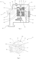
- the displacement adjustment system 10 comprises a variable displacement rotary volumetric pump 11, having a displacement adjustment chamber 13, and a pressure control valve 30 configured to control the pressure prevailing inside the displacement adjustment chamber 13 of the pump 11.
- variable displacement pump 11 comprises, inside a body 12 of the pump, a hollow stator 14 and a rotor 15 mounted inside the stator 14.
- the rotor 15 has a fixed axis of rotation Y while the stator 14 is mounted movably, in such a way that it can vary the eccentricity between its axis X and the axis of rotation Y of the rotor 15, thus varying the displacement of the pump 11.
- the rotor 15 of the pump 11 comprises a plurality of seats 15a configured to guide the translational movement of vanes 16 that rotate between one or more centering rings 17 and the stator 14.
- the pump 11 further comprises an intake port 18, hydraulically connected to a tank 60 of liquid to be pumped, and an outlet port 19.
- the thrust generated in the displacement adjustment chamber 13, reducing the eccentricity causes the stator 14 to move from a configuration of maximum displacement into a configuration of minimum displacement.
- the movement of the stator 14 under the effect of the thrust generated in the adjustment chamber 13 takes the form of pivoting.
- the movement may take another form, for example rotary or translational.
- the pump 11 further comprises a resilient element 20, for example a spring, capable of counteracting the thrust acting on the stator 14 generated in the displacement adjustment chamber 13 and bringing the pump 11 back to maximum eccentricity and, hence, to maximum displacement.
- a resilient element 20 for example a spring
- the pump 11 comprises a single displacement adjustment chamber 13 and the adjustment of the displacement is of incremental type, as there is a single thrust, generated in said single adjustment chamber 13, which acts against the resilient return element 20 and causes, once a given switching threshold has been exceeded, the variation of the displacement of the pump 11.
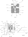
- control valve 30 of the adjustment system 10 is a spool valve comprising an outer valve body 31, a spool 32 which has a first piston 33 and a second piston 34 and is capable of sliding inside the valve body 31, and a resilient return element 38.
- the first piston 33 of the spool 32 has a thrust area 33a that defines, together with the outer valve body 31, a first chamber 35 of the control valve 30 (namely the control valve supply chamber).
- the resilient return element 38 of the control valve 30 is housed inside the second piston 34 of the spool 32 has a thrust area 34a, of opposite direction and, preferably, with a smaller surface area than the thrust area 33a of the first piston 33, which defines, together with the outer valve body 31, a second chamber 36 of the control valve 30 (namely the control valve counterthrust chamber).
- the first chamber 35 and the second chamber 36 of the control valve 30 are hydraulically connected by means of a pipe 37 made integral with the spool 32, in a longitudinal direction.
- This pipe 37 has appropriate dimensions so as to limit the flow rate of liquid passing through between the first and the second chambers 35, 36, limiting flow rate losses owing to leakage to the tank 60.
- the resilient element 38 is, for example, a spring having a first end 38a in abutment against the thrust area 34a of the second piston 34 of the spool 32 and a second end 38b in abutment against an end wall 31a of the outer valve body 31 so as to act in opposition to a hydraulic thrust exerted on the thrust area 33a of the first piston 33.
- the spool 32 of the control valve 30 comprises, preferably, a single difference in section between the first piston 33 and the second piston 34.
- This simplified geometry advantageously makes it possible to reduce production costs and produce a more axially compact spool.
- a first pipe 39 which may be partially obstructed by the first piston 33 of the spool 32, and a second pipe 40, both arranged radially with respect to the direction of sliding of the spool 32, are provided in the valve body 31 of the control valve 30.
- the first pipe 39 is hydraulically connected to the displacement adjustment chamber 13 while the second pipe 40 is hydraulically connected to the tank of liquid 60.
- the first pipe 39, and hence the displacement adjustment chamber 13 is hydraulically connected alternatively to the first chamber 35 of the control valve 30, and hence to the outlet port 19 of the pump 11, or to the second pipe 40 of the control valve 30, and hence to the tank of liquid 60, or is hydraulically connected simultaneously to the first chamber 35 and to the second pipe 40.
- the sliding of the spool 32 causes the control valve 30 to switch from a first state, in which the first piston 33 closes off the hydraulic connection between the first pipe 39 and the first chamber 35 of the control valve 30, leaving open the hydraulic connection between the first pipe 39 and the second pipe 40, to a second state, in which the first piston 33 closes off the hydraulic connection between the first pipe 39 and the second pipe 40, leaving open the hydraulic connection between the first pipe 39 and the first chamber 35 of the control valve 30.
- the adjustment system 10 further comprises a supply duct 50 for supplying a user member 51 that uses the liquid pumped, for example an internal combustion engine, which supply duct runs between the outlet port 19 and said user member 51 and along which is arranged, preferably, a filter 52.
- a supply duct 50 for supplying a user member 51 that uses the liquid pumped, for example an internal combustion engine, which supply duct runs between the outlet port 19 and said user member 51 and along which is arranged, preferably, a filter 52.
- a hydraulic thrust acts on the thrust area 33a of the first piston 33 of the spool 32.
- the first chamber 35 of the control valve 30 is hydraulically connected to the outlet port 19 of the pump 11 in stable mode and therefore the thrust area 33a of the first piston 33 is referred to as a passive thrust area.
- the adjustment system 10 further comprises a discharge valve 55, for example a 2/2 (i.e. two-way, two-position) solenoid valve, for hydraulically connecting, selectively, the second chamber 36 of the control valve 30 to the tank of liquid 60.
- a variable hydraulic thrust may act on the thrust area 34a of the second piston 34, referred to as an active counterthrust area, in opposition to the hydraulic thrust that acts on the thrust area 33a of the first piston 33.
- This hydraulic thrust acting on the thrust area 34a of the second piston 34 is greater in the case in which the discharge valve 55 is closed (first configuration of the adjustment system) and smaller in the case in which the discharge valve 55 is open (second configuration of the adjustment system).
- control valve 30 Since the control valve 30 has two thrust areas 33a, 34a against which the pumped liquid within the system exerts a pressure, the control valve 30 is a differential valve.
- the pressure of the pumped liquid which has flowed into the first chamber 35 of the control valve 30 and, through the pipe 37 integral with the spool 32, into the second chamber 36 of the control valve 30, generates a net hydraulic thrust on the spool 32 proportional to the difference between the thrust areas 33a, 34a of the first and second pistons 33, 34 of the spool 32.
- a first operating step shown in figure 4a , the balance of forces acting on the spool 32, resulting from said net hydraulic thrust and from the force exerted by the resilient element 38 of the control valve 30, keeps the control valve 30 in its first state, in which the first pipe 39 is in hydraulic connection with the second pipe 40 and not with the first chamber 35 of the control valve 30.
- the displacement adjustment chamber 13 is in hydraulic connection with the tank 60 and hence the pressure inside the chamber is low (in particular, below the threshold for switching the displacement of the pump), such that the stator 14 of the pump 11 remains in the configuration of maximum displacement.
- this first step which begins with the start-up of the pump 11, the pressure of the liquid pumped increases in proportion to the speed of rotation of the rotor 15 of the pump 11, as shown in the portion A HP of the graph of figure 4b .
- a second operating step of the adjustment system 10 in the first configuration shown in figure 5a
- the speed of rotation of the rotor 15 of the pump 11 is increased until the liquid pumped reaches a pressure value HP (above the threshold for switching the displacement of the pump).
- HP above the threshold for switching the displacement of the pump.
- the pressure HP of the liquid pumped is such that the net hydraulic thrust acting on the spool 32, overcoming the force exerted by the resilient element 38 of the control valve 30, brings the control valve 30 into its intermediate state and hence into its second state, in which the first pipe 39 is in hydraulic connection with the first chamber 35 of the control valve 30.
- the displacement adjustment chamber 13 is in hydraulic connection with the outlet port 19 of the pump 11 and hence the pressure inside the chamber rises above the threshold for switching the displacement of the pump, such that the stator 14 of the pump 11 moves into the configuration of minimum displacement.
- the pressure of the liquid pumped remains stable, equal to HP, when the speed of rotation of the rotor 15 of the pump 11 increases, as shown in the portion C of the graph of figure 5b .
- the spool 32 is subjected to a hydraulic thrust exerted on the thrust area 33a of the first piston 33 by the liquid pumped and a hydraulic thrust exerted on the thrust area 34a of the second piston 34 by the liquid contained in the second chamber 36 of the control valve 30, at a pressure lower than the liquid acting on the thrust area 33a of the first piston 33 since the second chamber 36 of the control valve 30 is in hydraulic connection with the tank 60.
- a first operating step shown in figure 6a , the balance of forces acting on the spool 32, resulting from said hydraulic thrusts and from the force exerted by the resilient element 38 of the control valve 30, keeps the control valve 30 in its first state, in which the first pipe 39 is in hydraulic connection with the second pipe 40 and not with the first chamber 35 of the control valve 30.
- the displacement adjustment chamber 13 is in hydraulic connection with the tank 60 and hence the pressure inside the chamber is low (in particular, below the threshold for switching the displacement of the pump), such that the stator 14 of the pump 11 remains in the configuration of maximum displacement.
- this first step which begins with the start-up of the pump 11, the pressure of the liquid pumped increases in proportion to the speed of rotation of the rotor 15 of the pump 11, as shown in the portion A LP of the graph of figure 6b .
- a second operating step of the adjustment system 10 in the second configuration shown in figure 7a
- the speed of rotation of the rotor 15 of the pump 10 is increased until the liquid pumped reaches a pressure value LP (above the threshold for switching the displacement of the pump).
- the pressure LP of the liquid pumped is such that the hydraulic thrust exerted on the thrust area 33a of the first piston 33, overcoming the hydraulic thrust exerted on the thrust area 34a of the second piston 34 and the force exerted by the resilient element 38 of the control valve 40, brings the control valve 30 into its intermediate state and hence into its second state, in which the first pipe 39 is in hydraulic connection with the first chamber 35 of the control valve 30.
- the displacement adjustment chamber 13 is in hydraulic connection with the outlet port 19 of the pump 11 and hence the pressure inside the chamber rises above the threshold for switching the displacement of the pump, such that the stator 14 of the pump 11 moves into the configuration of minimum displacement.
- the pressure of the liquid pumped remains stable when the speed of rotation of the rotor 15 of the pump 11 increases, as shown in the portion B of the graph of figure 7b .
- the pressure value LP reached during the stable outlet pressure mode of the pump 11 when the adjustment system 10 is operating in its second configuration is lower than the corresponding stable pressure value HP reached by the pump 11 when the adjustment system 10 is operating in its first configuration.
- the displacement adjustment system 110 comprises a variable displacement rotary volumetric pump 111, having a displacement adjustment chamber 113, and a control valve 130 configured to control the pressure prevailing inside the displacement adjustment chamber 113 of the pump 111.
- variable displacement rotary volumetric pump 111 of the second embodiment is the same as that of the first embodiment, shown in figure 2 , reference being made to the description thereof.
- control valve 130 of the second embodiment is the same as that of the first embodiment, reference being made to the description thereof, with the exception of the fact that the spool 132 does not have the pipe integral between the first chamber 135 and the second chamber 136 of the control valve 130.
- the first pipe 139 of the valve body 131 of the control valve 130 is hydraulically connected to the displacement adjustment chamber 113 of the pump 111 while the second pipe 140 is hydraulically connected to the tank of liquid 160.
- the first pipe 139, and hence the displacement adjustment chamber 113 is alternatively connected, in a first state of the control valve 130, to the first chamber 135 of the control valve 130, and hence to the outlet port 119 of the pump 111, or, in a second state of the control valve 130, to the second pipe 140 of the control valve 30, and hence to the tank of liquid 160, or, in an intermediate state, is hydraulically connected simultaneously to the first chamber 135 and to the second pipe 140.
- the adjustment system 110 comprises a supply duct 150 for supplying a user member 151 that uses the liquid pumped, for example an internal combustion engine, which supply duct runs between the outlet port 119 and said user member 151 and along which is arranged, preferably, a filter 152.
- a first outlet duct 153 of the system branching off from the supply duct 150, preferably downstream of the filter 152 (with reference to the direction of flow of the liquid in the supply duct 150), hydraulically connects the first chamber 135 of the control valve 130 to the outlet port 119 of the pump 111.
- a hydraulic thrust acts on the thrust area 133a of the first piston 133 of the spool 132.
- the first chamber 135 of the control valve 130 is hydraulically connected to the outlet port 119 of the pump 111 in stable mode and therefore the thrust area 133a of the first piston 133 is referred to as a passive thrust area.
- the adjustment system 110 comprises a discharge valve 155, for example a 3/2 (i.e. three-way, two-position) solenoid valve for alternatively connecting, selectively, the second chamber 136 of the control valve 130 respectively to the tank of liquid 160 or to a second outlet duct 154, branching off from the supply duct 150, preferably downstream of the filter 152.
- a variable hydraulic thrust may act on the thrust area 134a of the second piston 134, referred to as an active counterthrust area, in opposition to the hydraulic thrust that acts on the thrust area 133a of the first piston 133.
- This hydraulic thrust acting on the thrust area 134a of the second piston 134 is greater in the case in which the discharge valve 155 connects the second chamber 136 of the control valve 130 to the second outlet duct 154, and hence to the outlet port 119 of the pump 111 (first configuration of the adjustment system), and smaller in the case in which the discharge valve 155 connects said second chamber 136 to the tank 160 (second configuration of the adjustment system).
- this makes it possible to select, according to the requirements of the system, the pressure threshold for the pumped liquid that causes the control valve 130 to switch from the first to the second state and hence the pressure threshold beyond which the pump 111, reducing its displacement, operates in stable outlet pressure mode.
- control valve 130 Since the control valve 130 has two thrust areas 133a, 134a against which the pumped liquid within the system exerts a pressure, the control valve 130 is a differential valve also in the case of the second embodiment.
- the pressure of the pumped liquid which has flowed into the first chamber 135 of the control valve 130 and, through the second outlet duct 154 and the discharge valve 155, into the second chamber 136 of the control valve 130, generates a net hydraulic thrust on the spool 132 proportional to the difference between the thrust areas 133a, 134a of the first and second pistons 133, 134 of the spool 132.
- a first operating step shown in figure 10a , the balance of forces acting on the spool 132, resulting from said net hydraulic thrust and from the force exerted by the resilient element 138 of the control valve 130, keeps the control valve 130 in its first state, in which the first pipe 139 is in hydraulic connection with the second pipe 140 and not with the first chamber 135 of the control valve 130.
- the displacement adjustment chamber 113 is in hydraulic connection with the tank 160 and hence the pressure inside the chamber is low (in particular, below the threshold for switching the displacement of the pump), such that the stator 114 of the pump 111 remains in the configuration of maximum displacement.
- this first step which begins with the start-up of the pump 111, the pressure of the liquid pumped increases in proportion to the speed of rotation of the rotor 115 of the pump 111, as shown in the portion A HP of the graph of figure 10b .
- a second operating step of the adjustment system 110 in the first configuration shown in figure 11a
- the speed of rotation of the rotor 115 of the pump 111 is increased until the liquid pumped reaches a pressure value HP' (above the threshold for switching the displacement of the pump).
- HP' of the liquid pumped is such that the net hydraulic thrust acting on the spool 132, overcoming the force exerted by the resilient element 138 of the control valve 130, brings the control valve 130 into its intermediate state and hence into its second state, in which the first pipe 139 is in hydraulic connection with the first chamber 135 of the control valve 130.
- the displacement adjustment chamber 113 is in hydraulic connection with the outlet port 119 of the pump 111 and hence the pressure inside the chamber rises above the threshold for switching the displacement of the pump, such that the stator 114 of the pump 111 moves into the configuration of minimum displacement.
- the passage of the displacement adjustment valve 130 through the intermediate state in which the pressure in the displacement adjustment chamber 130 assumes values between the pressure of the liquid in the outlet duct 153 and the pressure of the liquid in the tank 160, as a function of local leakage from the first piston 133 of the spool 132, allows gradual switching of the displacement of the pump.
- the pressure of the liquid pumped remains stable, equal to HP', when the speed of rotation of the rotor 115 of the pump 111 increases, as shown in the portion C of the graph of figure 11b .
- the spool 132 is subjected to a hydraulic thrust exerted on the thrust area 133a of the first piston 133 by the liquid pumped and a hydraulic thrust exerted on the thrust area 134a of the second piston 134 by the liquid contained in the second chamber 136 of the control valve 130, at a pressure lower than the liquid acting on the thrust area 133a of the first piston 133 since the second chamber 136 of the control valve 130 is in hydraulic connection with the tank 160.
- a first operating step shown in figure 12a , the balance of forces acting on the spool 132, resulting from said hydraulic thrusts and from the force exerted by the resilient element 138 of the control valve 130, keeps the control valve 130 in its first state, in which the first pipe 139 is in hydraulic connection with the second pipe 140 and not with the first chamber 135 of the control valve 130.
- the displacement adjustment chamber 113 is in hydraulic connection with the tank 160 and hence the pressure inside the chamber is low, in particular below the threshold for switching the displacement of the pump, such that the stator 114 of the pump 111 remains in the configuration of maximum displacement.
- this first step which begins with the start-up of the pump 111, the pressure of the liquid pumped increases in proportion to the speed of rotation of the rotor 115 of the pump 111, as shown in the portion A LP of the graph of figure 12b .
- a second operating step of the adjustment system 110 in the second configuration, shown in figure 13a the speed of rotation of the rotor 115 of the pump 111 is increased until the liquid pumped reaches a pressure value LP' (above the threshold for switching the displacement of the pump).
- the pressure LP' of the liquid pumped is such that the hydraulic thrust exerted on the thrust area 133a of the first piston 133, overcoming the hydraulic thrust exerted on the thrust area 134a of the second piston 134 and the force exerted by the resilient element 138 of the control valve 130, brings the control valve 130 into its intermediate state and hence into its second state, in which the first pipe 139 is in hydraulic connection with the first chamber 135 of the control valve 130.
- the displacement adjustment chamber 113 is in hydraulic connection with the outlet port 119 of the pump 111 and hence the pressure inside the chamber rises above the threshold for switching the displacement of the pump, such that the stator 114 of the pump 111 moves into the configuration of minimum displacement.
- the passage of the displacement adjustment valve 130 through the intermediate state in which the pressure in the displacement adjustment chamber 130 assumes values between the pressure of the liquid in the outlet duct 153 and the pressure of the liquid in the tank 160, as a function of local leakage from the first piston 133 of the spool 132, allows gradual switching of the displacement of the pump.
- the pressure of the liquid pumped remains stable when the speed of rotation of the rotor 115 of the pump 111 increases, as shown in the portion B of the graph of figure 13b .
- the pressure value LP' reached during the stable outlet pressure mode of the pump 111 when the adjustment system 110 is operating in its second configuration is lower than the corresponding stable pressure value HP' reached by the pump 111 when the adjustment system 110 is operating in its first configuration.
Landscapes
- Engineering & Computer Science (AREA)
- Mechanical Engineering (AREA)
- General Engineering & Computer Science (AREA)
- Details And Applications Of Rotary Liquid Pumps (AREA)
- Rotary Pumps (AREA)
Claims (13)
- System zur Einstellung der Verdrängung (10; 110) für eine Pumpe mit variabler Verdrängung (11; 111), wobei das System umfasst- eine Pumpe (11; 111) mit variabler Verdrängung, umfassend einen Rotor (15; 115), einen Stator (14; 114), der so ausgebildet ist, dass er so bewegt werden kann, dass die Exzentrizität zwischen seiner Achse (X) und der Drehachse (Y) des Rotors (15; 115) variiert wird, wodurch die Verdrängung der Pumpe (11; 111) variiert wird, eine Auslassöffnung (19; 119), eine Kammer (13; 113) zur Einstellung der Verdrängung, die so ausgebildet ist, dass ein in ihr herrschender Druck einen Schub auf den Stator (14; 114) erzeugt, der geeignet ist, den Stator (14; 114) zu bewegen, wodurch eine Änderung der Exzentrizität bewirkt wird, und ein elastisches Element (20; 120), das dem auf den Stator (14; 114) wirkenden Schub entgegenwirken kann,- ein Druckregelschieberventil (30; 130), das einen äußeren Ventilkörper (31; 131), einen Schieber (32; 132), der in dem Ventilkörper (31; 131) gleiten kann und einen ersten Kolben (33; 133) und einen zweiten Kolben (34; 134) aufweist, und ein elastisches Rückstellelement (38; 138) umfasst, wobei der erste Kolben (33; 133) eine Druckfläche (33a; 133a) aufweist, die zusammen mit dem Ventilkörper (31; 131) eine erste Kammer (35; 135) des Druckregelschieberventils (30; 130) definiert und die mit der Auslassöffnung (19; 119) der Pumpe (11; 111) mittels eines ersten Auslasskanals (53; 153) hydraulisch verbunden ist, so dass ein hydraulischer Schub auf die Druckfläche (33a; 133a) des ersten Kolbens (33; 133) wirkt, wobei das elastische Rückstellelement (38; 138) ausgebildet ist, um dem hydraulischen Schub, der auf die Druckfläche (33a; 133a) des ersten Kolbens (33; 133) wirkt, entgegenzuwirken, wobei das Druckregelschieberventil (30; 130) ferner, das in dem äußeren Ventilkörper (31; 131) vorgesehen ist, ein erstes Einstellrohr (39; 139), das hydraulisch mit der Kammer (13; 113) zur Einstellung der Verdrängung verbunden ist, und ein zweites Einstellrohr (40; 140), das hydraulisch mit einem Flüssigkeitstank (60; 160) und wahlweise mittels des Schiebers (32; 132) mit dem ersten Einstellrohr (39; 139) verbunden ist, wobei die Kammer (13; 113) zur Einstellung der Verdrängung hydraulisch mit der Auslassöffnung (19; 119) der Pumpe (11; 111) über das Druckregelschieberventil (30; 130) verbunden ist,wobei in einem ersten Zustand des Druckregelschieberventils (30; 130) der erste Kolben (33; 133) ausgebildet ist, um die hydraulische Verbindung zwischen dem ersten Einstellrohr (39; 139) und der ersten Kammer (35; 135) des Druckregelschieberventils (30; 130) zu schließen, und die hydraulische Verbindung zwischen dem ersten Einstellrohr (39; 139) und dem zweiten Einstellrohr (40; 140) offen zu lassen, und in einem zweiten Zustand des Druckregelschieberventils (30; 130) ist der erste Kolben (33; 133) ausgebildet, die hydraulische Verbindung zwischen dem ersten Einstellrohr (39; 139) und dem zweiten Einstellrohr (40; 140) zu schließen und die hydraulische Verbindung zwischen dem ersten Einstellrohr (39; 139) und der ersten Kammer (35; 135) des Druckregelschieberventils (30; 130) offen zu lassen, wobei der zweite Kolben (34; 134) des Druckregelschieberventils (30; 130) eine Druckfläche (34a; 134a) in entgegengesetzter Richtung zu der Druckfläche (33a; 133a) des ersten Kolbens (33; 133) aufweist,dadurch gekennzeichnet, dass die Druckfläche (34a; 134a) des zweiten Kolbens (34; 134) wahlweise mit dem Flüssigkeitstank (60; 160) mittels eines Magnetventils (55; 155) hydraulisch verbunden ist, so dass ein hydraulischer Druck auf die Druckfläche (34a; 134a) des zweiten Kolbens (34; 134) entgegengesetzt zu dem hydraulischen Druck wirkt, der auf die Druckfläche (33a; 133a) des ersten Kolbens (33; 133) wirkt.
- Einstellsystem (10; 110) nach Anspruch 1, bei dem der erste Kolben (33; 133) so ausgebildet ist, dass er in einem Zwischenzustand des Druckregelschieberventils (30; 130) die hydraulische Verbindung zwischen dem ersten Einstellrohr (39; 139) und dem zweiten Einstellrohr (40; 140) sowie zwischen dem ersten Einstellrohr (39; 139) und der ersten Kammer (35; 135) des Druckregelschieberventils (30; 130) nur teilweise blockiert.
- Einstellsystem (10; 110) nach Anspruch 1 oder 2, in dem die Druckfläche (34a; 134a) des zweiten Kolbens (34; 134) des Schiebers (32; 132) eine kleinere Fläche aufweist als die Druckfläche (33a; 133a) des ersten Kolbens (33; 133) des Schiebers (32; 132).
- Einstellsystem (10; 110) nach einem der vorhergehenden Ansprüche, bei dem der Schieber (32; 132) einen einzigen Unterschied in dem Querschnitt zwischen dem ersten Kolben (33; 133) und dem zweiten Kolben (34; 134) umfasst.
- Einstellsystem (10) nach einem der vorhergehenden Ansprüche, bei dem der Schieber (32) ein mit ihm integral ausgebildetem Rohr (37) umfasst, das die Druckfläche (33a) des ersten Kolbens (33) des Schiebers (32) mit der Druckfläche (34a) des zweiten Kolbens (34) des Schiebers (32) hydraulisch verbindet.
- Einstellsystem (10) nach Anspruch 1, bei dem das Magnetventil (55), das wahlweise die Druckfläche (34a) des zweiten Kolbens (34) mit dem Flüssigkeitstank (60) hydraulisch verbindet, ein 2/2-Ventil (55) ist.
- Einstellsystem (110) nach einem der Ansprüche 1 bis 4, bei dem die Druckfläche (134a) des zweiten Kolbens (134) wahlweise über das Magnetventil (155) mit dem Flüssigkeitstank (160) oder alternativ mit der Auslassöffnung (119) der Pumpe (111) hydraulisch verbunden ist.
- Einstellsystem (110) nach Anspruch 7, bei dem das Magnetventil (155) ein 3/2-Ventil ist.
- Verfahren zum Einstellen der Verdrängung einer Pumpe mit variabler Verdrängung (11; 111), die eine Kammer (13; 113) zur Einstellung der Verdrängung umfasst, mittels eines Einstellsystem (10; 110), das ein Druckregelschieberventil (30; 130) umfasst, wobei das Verfahren die Schritte umfasst:- Platzieren der Kammer (13; 113) zur Einstellung der Verdrängung der Pumpe (11; 111), die über das Druckregelschieberventil (30; 130) mit einem Flüssigkeitstank (60; 160) und nicht mit einer Auslassöffnung (19; 119) der Pumpe (11; 111) hydraulisch verbunden ist, um die Pumpe (11; 111) in der Konfiguration maximaler Verdrängung zu betreiben;- unter der Wirkung eines hydraulischen Schubs, der auf eine Druckfläche (33a; 133a) eines ersten Kolbens (33; 133) des Schiebers (32; 132) des Druckregelschieberventils (30; 130) einwirkt, die Platzierung der Kammer (13; 113) zur Einstellung der Verdrängung der Pumpe (11; 111) mittels des Druckregelschieberventils (30; 130) in hydraulischer Verbindung mit der Auslassöffnung (19; 119) der Pumpe (11; 111) und nicht mit dem Flüssigkeitstank (60; 160), um die Pumpe (11; 111) in der Konfiguration der minimalen Verdrängung zu betreiben;
und- wahlweise Platzierung einer Druckfläche (34a; 134a) eines zweiten Kolbens (34; 134) des Schiebers (32; 132) in entgegengesetzter Richtung zur Druckfläche (33a; 133a) des ersten Kolbens (33; 133) mittels eines Magnetventils (55; 155) in hydraulischer Verbindung mit einem Flüssigkeitstank (60; 160), um die Pumpe (11; 111) in der Konfiguration der minimalen Verlagerung entweder in einem ersten Modus mit stabilem Ausgangsdruck (HP; HP'), wenn das Magnetventil (55; 155) geschlossen ist, oder in einem zweiten Modus mit stabilem Ausgangsdruck (LP; LP'), der niedriger ist als der erste Modus mit stabilem Ausgangsdruck, wenn das Magnetventil (55; 155) geöffnet ist, zu betreiben. - Einstellverfahren nach Anspruch 9, ferner den Schritt umfassend:- unter der Wirkung des hydraulischen Schubs, der auf die Druckfläche (33a; 133a) des ersten Kolbens (33; 133) des Schiebers (32; 132) des Druckregelschieberventils (30; 130) wirkt, Platzierung der Kammer (13; 113) zur Einstellung der Verdrängung der Pumpe (11; 111) sowohl mit der Auslassöffnung (19; 119) der Pumpe (11; 111) als auch mit dem Flüssigkeitstank (60; 160) in hydraulischer Verbindung.
- Einstellverfahren nach Anspruch 9 oder 10, ferner den Schritt umfassend:- Platzierung der Druckfläche (33a) des ersten Kolbens (33) des Schiebers (32) mit der Druckfläche (34a) des zweiten Kolbens (34) des Schiebers (32) über ein mit dem Schieber (32) integral ausgebildetem Rohr (37) in hydraulischer Verbindung.
- Einstellverfahren nach Anspruch 9 oder 10, ferner den Schritt umfassend:- Platzierung der Druckfläche (134a) des zweiten Kolbens (134) des Schiebers (132) wahlweise in hydraulischer Verbindung mit der Auslassöffnung (119) der Pumpe (111).
- Einstellverfahren nach Anspruch 12, bei dem der Schritt, die Druckfläche (134a) des zweiten Kolbens (134) des Schiebers (132) in hydraulischer Verbindung mit einem Flüssigkeitstank (160) zu platzieren, nicht gleichzeitig mit dem Schritt ausgeführt wird, die Druckfläche (134a) des zweiten Kolbens (134) des Schiebers (132) in hydraulischer Verbindung mit der Auslassöffnung (119) der Pumpe (111) zu platzieren.
Applications Claiming Priority (2)
| Application Number | Priority Date | Filing Date | Title |
|---|---|---|---|
| IT102018000020377A IT201800020377A1 (it) | 2018-12-20 | 2018-12-20 | Sistema di regolazione della cilindrata di una pompa a cilindrata variabile |
| PCT/EP2019/085961 WO2020127491A1 (en) | 2018-12-20 | 2019-12-18 | Displacement adjustment system for a variable displacement pump |
Publications (2)
| Publication Number | Publication Date |
|---|---|
| EP3899282A1 EP3899282A1 (de) | 2021-10-27 |
| EP3899282B1 true EP3899282B1 (de) | 2024-09-04 |
Family
ID=66166293
Family Applications (1)
| Application Number | Title | Priority Date | Filing Date |
|---|---|---|---|
| EP19818191.9A Active EP3899282B1 (de) | 2018-12-20 | 2019-12-18 | Verdrängungseinstellungssystem für eine variable verdrängerpumpe |
Country Status (3)
| Country | Link |
|---|---|
| EP (1) | EP3899282B1 (de) |
| IT (1) | IT201800020377A1 (de) |
| WO (1) | WO2020127491A1 (de) |
Families Citing this family (1)
| Publication number | Priority date | Publication date | Assignee | Title |
|---|---|---|---|---|
| CN114704676B (zh) * | 2022-04-25 | 2022-12-02 | 中联重科股份有限公司 | 单向阀及具有单向阀的液压控制装置 |
Family Cites Families (4)
| Publication number | Priority date | Publication date | Assignee | Title |
|---|---|---|---|---|
| DE10234621A1 (de) * | 2002-07-29 | 2004-02-19 | Zf Lenksysteme Gmbh | Regeleinrichtung für eine Verstellpumpe, insbesondere eine Flügelzellenpumpe |
| JP5278779B2 (ja) * | 2010-12-21 | 2013-09-04 | アイシン精機株式会社 | オイルポンプ |
| WO2012113437A1 (en) * | 2011-02-21 | 2012-08-30 | Pierburg Pump Technology Gmbh | A variable displacement lubricant pump with a pressure control valve having a preload control arrangement |
| KR101505775B1 (ko) | 2014-04-15 | 2015-03-26 | 명화공업주식회사 | 하나의 챔버와 2방 밸브를 이용한 2단 가변 오일펌프 |
-
2018
- 2018-12-20 IT IT102018000020377A patent/IT201800020377A1/it unknown
-
2019
- 2019-12-18 WO PCT/EP2019/085961 patent/WO2020127491A1/en not_active Ceased
- 2019-12-18 EP EP19818191.9A patent/EP3899282B1/de active Active
Also Published As
| Publication number | Publication date |
|---|---|
| WO2020127491A1 (en) | 2020-06-25 |
| EP3899282A1 (de) | 2021-10-27 |
| IT201800020377A1 (it) | 2020-06-20 |
Similar Documents
| Publication | Publication Date | Title |
|---|---|---|
| JP5193069B2 (ja) | カムシャフトタイミングアジャスタ及びその制御要素の油圧回路 | |
| US5562432A (en) | Variable displacement pump having throttled control passages | |
| EP1979616B1 (de) | Verstellflügelpumpensystem mit gleitdruck | |
| EP2668379B1 (de) | Ölpumpe mit wählbarem auslassdruck | |
| KR101118073B1 (ko) | 압력 이송 밸브 | |
| EP2971779B1 (de) | Flügelzellenpumpe mit mehreren steuerkammern | |
| EP1790855A2 (de) | Hydraulisches Pumpensystem mit variablen Durchsatz und Druck | |
| KR20090074059A (ko) | 펌프 출력 압력 제어용 제어 시스템 및 제어 방법 | |
| WO2008137037A1 (en) | Hydraulic pump with variable flow and pressure and improved open-loop electric control | |
| JP2005133716A (ja) | 可変目標調整器を備えた可変容量形ベーンポンプ | |
| US10794468B2 (en) | Hydraulic system for a transmission of a motor vehicle | |
| JP2002349449A (ja) | 可変目標値の調節装置を備える可変容積形ベーンポンプ | |
| WO2014113152A1 (en) | Hydraulic piston pump with throttle control | |
| EP3899282B1 (de) | Verdrängungseinstellungssystem für eine variable verdrängerpumpe | |
| US6186750B1 (en) | Oil pump control valve spool with pilot pressure relief valve | |
| CN111173916B (zh) | 用于机动车变速器的液压系统的冷却优先阀 | |
| US8550796B2 (en) | Variable capacity fluidic machine | |
| RU2695932C1 (ru) | Устройство и способ поддержания созданного гидравлического давления | |
| US11867298B2 (en) | System pressure valve for a hydraulic system of a motor vehicle transmission | |
| CN109139176B (zh) | 一种基于定排量机油泵的压力控制系统 | |
| US6478549B1 (en) | Hydraulic pump with speed dependent recirculation valve | |
| JP2017020562A (ja) | リリーフバルブ | |
| CN102678543A (zh) | 齿轮泵和调整输送量的移动单元 | |
| EP3203060B1 (de) | Hochdruckdieselkraftstoffpumpe | |
| JP2016114204A (ja) | 圧力調整システム |
Legal Events
| Date | Code | Title | Description |
|---|---|---|---|
| STAA | Information on the status of an ep patent application or granted ep patent |
Free format text: STATUS: UNKNOWN |
|
| STAA | Information on the status of an ep patent application or granted ep patent |
Free format text: STATUS: THE INTERNATIONAL PUBLICATION HAS BEEN MADE |
|
| PUAI | Public reference made under article 153(3) epc to a published international application that has entered the european phase |
Free format text: ORIGINAL CODE: 0009012 |
|
| STAA | Information on the status of an ep patent application or granted ep patent |
Free format text: STATUS: REQUEST FOR EXAMINATION WAS MADE |
|
| 17P | Request for examination filed |
Effective date: 20210720 |
|
| AK | Designated contracting states |
Kind code of ref document: A1 Designated state(s): AL AT BE BG CH CY CZ DE DK EE ES FI FR GB GR HR HU IE IS IT LI LT LU LV MC MK MT NL NO PL PT RO RS SE SI SK SM TR |
|
| DAV | Request for validation of the european patent (deleted) | ||
| DAX | Request for extension of the european patent (deleted) | ||
| P01 | Opt-out of the competence of the unified patent court (upc) registered |
Effective date: 20230601 |
|
| GRAP | Despatch of communication of intention to grant a patent |
Free format text: ORIGINAL CODE: EPIDOSNIGR1 |
|
| STAA | Information on the status of an ep patent application or granted ep patent |
Free format text: STATUS: GRANT OF PATENT IS INTENDED |
|
| INTG | Intention to grant announced |
Effective date: 20240404 |
|
| GRAS | Grant fee paid |
Free format text: ORIGINAL CODE: EPIDOSNIGR3 |
|
| GRAA | (expected) grant |
Free format text: ORIGINAL CODE: 0009210 |
|
| STAA | Information on the status of an ep patent application or granted ep patent |
Free format text: STATUS: THE PATENT HAS BEEN GRANTED |
|
| AK | Designated contracting states |
Kind code of ref document: B1 Designated state(s): AL AT BE BG CH CY CZ DE DK EE ES FI FR GB GR HR HU IE IS IT LI LT LU LV MC MK MT NL NO PL PT RO RS SE SI SK SM TR |
|
| REG | Reference to a national code |
Ref country code: GB Ref legal event code: FG4D |
|
| REG | Reference to a national code |
Ref country code: CH Ref legal event code: EP |
|
| REG | Reference to a national code |
Ref country code: IE Ref legal event code: FG4D |
|
| REG | Reference to a national code |
Ref country code: DE Ref legal event code: R096 Ref document number: 602019058400 Country of ref document: DE |
|
| REG | Reference to a national code |
Ref country code: LT Ref legal event code: MG9D |
|
| REG | Reference to a national code |
Ref country code: NL Ref legal event code: MP Effective date: 20240904 |
|
| PG25 | Lapsed in a contracting state [announced via postgrant information from national office to epo] |
Ref country code: NO Free format text: LAPSE BECAUSE OF FAILURE TO SUBMIT A TRANSLATION OF THE DESCRIPTION OR TO PAY THE FEE WITHIN THE PRESCRIBED TIME-LIMIT Effective date: 20241204 |
|
| PG25 | Lapsed in a contracting state [announced via postgrant information from national office to epo] |
Ref country code: FI Free format text: LAPSE BECAUSE OF FAILURE TO SUBMIT A TRANSLATION OF THE DESCRIPTION OR TO PAY THE FEE WITHIN THE PRESCRIBED TIME-LIMIT Effective date: 20240904 Ref country code: GR Free format text: LAPSE BECAUSE OF FAILURE TO SUBMIT A TRANSLATION OF THE DESCRIPTION OR TO PAY THE FEE WITHIN THE PRESCRIBED TIME-LIMIT Effective date: 20241205 Ref country code: PL Free format text: LAPSE BECAUSE OF FAILURE TO SUBMIT A TRANSLATION OF THE DESCRIPTION OR TO PAY THE FEE WITHIN THE PRESCRIBED TIME-LIMIT Effective date: 20240904 |
|
| PG25 | Lapsed in a contracting state [announced via postgrant information from national office to epo] |
Ref country code: BG Free format text: LAPSE BECAUSE OF FAILURE TO SUBMIT A TRANSLATION OF THE DESCRIPTION OR TO PAY THE FEE WITHIN THE PRESCRIBED TIME-LIMIT Effective date: 20240904 |
|
| PG25 | Lapsed in a contracting state [announced via postgrant information from national office to epo] |
Ref country code: LV Free format text: LAPSE BECAUSE OF FAILURE TO SUBMIT A TRANSLATION OF THE DESCRIPTION OR TO PAY THE FEE WITHIN THE PRESCRIBED TIME-LIMIT Effective date: 20240904 |
|
| PG25 | Lapsed in a contracting state [announced via postgrant information from national office to epo] |
Ref country code: HR Free format text: LAPSE BECAUSE OF FAILURE TO SUBMIT A TRANSLATION OF THE DESCRIPTION OR TO PAY THE FEE WITHIN THE PRESCRIBED TIME-LIMIT Effective date: 20240904 |
|
| PG25 | Lapsed in a contracting state [announced via postgrant information from national office to epo] |
Ref country code: ES Free format text: LAPSE BECAUSE OF FAILURE TO SUBMIT A TRANSLATION OF THE DESCRIPTION OR TO PAY THE FEE WITHIN THE PRESCRIBED TIME-LIMIT Effective date: 20240904 Ref country code: RS Free format text: LAPSE BECAUSE OF FAILURE TO SUBMIT A TRANSLATION OF THE DESCRIPTION OR TO PAY THE FEE WITHIN THE PRESCRIBED TIME-LIMIT Effective date: 20241204 |
|
| PG25 | Lapsed in a contracting state [announced via postgrant information from national office to epo] |
Ref country code: RS Free format text: LAPSE BECAUSE OF FAILURE TO SUBMIT A TRANSLATION OF THE DESCRIPTION OR TO PAY THE FEE WITHIN THE PRESCRIBED TIME-LIMIT Effective date: 20241204 Ref country code: PL Free format text: LAPSE BECAUSE OF FAILURE TO SUBMIT A TRANSLATION OF THE DESCRIPTION OR TO PAY THE FEE WITHIN THE PRESCRIBED TIME-LIMIT Effective date: 20240904 Ref country code: NO Free format text: LAPSE BECAUSE OF FAILURE TO SUBMIT A TRANSLATION OF THE DESCRIPTION OR TO PAY THE FEE WITHIN THE PRESCRIBED TIME-LIMIT Effective date: 20241204 Ref country code: LV Free format text: LAPSE BECAUSE OF FAILURE TO SUBMIT A TRANSLATION OF THE DESCRIPTION OR TO PAY THE FEE WITHIN THE PRESCRIBED TIME-LIMIT Effective date: 20240904 Ref country code: HR Free format text: LAPSE BECAUSE OF FAILURE TO SUBMIT A TRANSLATION OF THE DESCRIPTION OR TO PAY THE FEE WITHIN THE PRESCRIBED TIME-LIMIT Effective date: 20240904 Ref country code: GR Free format text: LAPSE BECAUSE OF FAILURE TO SUBMIT A TRANSLATION OF THE DESCRIPTION OR TO PAY THE FEE WITHIN THE PRESCRIBED TIME-LIMIT Effective date: 20241205 Ref country code: FI Free format text: LAPSE BECAUSE OF FAILURE TO SUBMIT A TRANSLATION OF THE DESCRIPTION OR TO PAY THE FEE WITHIN THE PRESCRIBED TIME-LIMIT Effective date: 20240904 Ref country code: ES Free format text: LAPSE BECAUSE OF FAILURE TO SUBMIT A TRANSLATION OF THE DESCRIPTION OR TO PAY THE FEE WITHIN THE PRESCRIBED TIME-LIMIT Effective date: 20240904 Ref country code: BG Free format text: LAPSE BECAUSE OF FAILURE TO SUBMIT A TRANSLATION OF THE DESCRIPTION OR TO PAY THE FEE WITHIN THE PRESCRIBED TIME-LIMIT Effective date: 20240904 |
|
| REG | Reference to a national code |
Ref country code: AT Ref legal event code: MK05 Ref document number: 1720656 Country of ref document: AT Kind code of ref document: T Effective date: 20240904 |
|
| PG25 | Lapsed in a contracting state [announced via postgrant information from national office to epo] |
Ref country code: NL Free format text: LAPSE BECAUSE OF FAILURE TO SUBMIT A TRANSLATION OF THE DESCRIPTION OR TO PAY THE FEE WITHIN THE PRESCRIBED TIME-LIMIT Effective date: 20240904 |
|
| PG25 | Lapsed in a contracting state [announced via postgrant information from national office to epo] |
Ref country code: PT Free format text: LAPSE BECAUSE OF FAILURE TO SUBMIT A TRANSLATION OF THE DESCRIPTION OR TO PAY THE FEE WITHIN THE PRESCRIBED TIME-LIMIT Effective date: 20250106 Ref country code: IS Free format text: LAPSE BECAUSE OF FAILURE TO SUBMIT A TRANSLATION OF THE DESCRIPTION OR TO PAY THE FEE WITHIN THE PRESCRIBED TIME-LIMIT Effective date: 20250104 |
|
| PG25 | Lapsed in a contracting state [announced via postgrant information from national office to epo] |
Ref country code: RO Free format text: LAPSE BECAUSE OF FAILURE TO SUBMIT A TRANSLATION OF THE DESCRIPTION OR TO PAY THE FEE WITHIN THE PRESCRIBED TIME-LIMIT Effective date: 20240904 Ref country code: SM Free format text: LAPSE BECAUSE OF FAILURE TO SUBMIT A TRANSLATION OF THE DESCRIPTION OR TO PAY THE FEE WITHIN THE PRESCRIBED TIME-LIMIT Effective date: 20240904 |
|
| PG25 | Lapsed in a contracting state [announced via postgrant information from national office to epo] |
Ref country code: EE Free format text: LAPSE BECAUSE OF FAILURE TO SUBMIT A TRANSLATION OF THE DESCRIPTION OR TO PAY THE FEE WITHIN THE PRESCRIBED TIME-LIMIT Effective date: 20240904 Ref country code: AT Free format text: LAPSE BECAUSE OF FAILURE TO SUBMIT A TRANSLATION OF THE DESCRIPTION OR TO PAY THE FEE WITHIN THE PRESCRIBED TIME-LIMIT Effective date: 20240904 |
|
| PG25 | Lapsed in a contracting state [announced via postgrant information from national office to epo] |
Ref country code: CZ Free format text: LAPSE BECAUSE OF FAILURE TO SUBMIT A TRANSLATION OF THE DESCRIPTION OR TO PAY THE FEE WITHIN THE PRESCRIBED TIME-LIMIT Effective date: 20240904 |
|
| PG25 | Lapsed in a contracting state [announced via postgrant information from national office to epo] |
Ref country code: SK Free format text: LAPSE BECAUSE OF FAILURE TO SUBMIT A TRANSLATION OF THE DESCRIPTION OR TO PAY THE FEE WITHIN THE PRESCRIBED TIME-LIMIT Effective date: 20240904 Ref country code: IT Free format text: LAPSE BECAUSE OF FAILURE TO SUBMIT A TRANSLATION OF THE DESCRIPTION OR TO PAY THE FEE WITHIN THE PRESCRIBED TIME-LIMIT Effective date: 20240904 |
|
| REG | Reference to a national code |
Ref country code: DE Ref legal event code: R097 Ref document number: 602019058400 Country of ref document: DE |
|
| PG25 | Lapsed in a contracting state [announced via postgrant information from national office to epo] |
Ref country code: MC Free format text: LAPSE BECAUSE OF FAILURE TO SUBMIT A TRANSLATION OF THE DESCRIPTION OR TO PAY THE FEE WITHIN THE PRESCRIBED TIME-LIMIT Effective date: 20240904 |
|
| PG25 | Lapsed in a contracting state [announced via postgrant information from national office to epo] |
Ref country code: DK Free format text: LAPSE BECAUSE OF FAILURE TO SUBMIT A TRANSLATION OF THE DESCRIPTION OR TO PAY THE FEE WITHIN THE PRESCRIBED TIME-LIMIT Effective date: 20240904 |
|
| PLBE | No opposition filed within time limit |
Free format text: ORIGINAL CODE: 0009261 |
|
| STAA | Information on the status of an ep patent application or granted ep patent |
Free format text: STATUS: NO OPPOSITION FILED WITHIN TIME LIMIT |
|
| REG | Reference to a national code |
Ref country code: CH Ref legal event code: PL |
|
| 26N | No opposition filed |
Effective date: 20250605 |
|
| PG25 | Lapsed in a contracting state [announced via postgrant information from national office to epo] |
Ref country code: LU Free format text: LAPSE BECAUSE OF NON-PAYMENT OF DUE FEES Effective date: 20241218 |
|
| GBPC | Gb: european patent ceased through non-payment of renewal fee |
Effective date: 20241218 |
|
| PG25 | Lapsed in a contracting state [announced via postgrant information from national office to epo] |
Ref country code: SE Free format text: LAPSE BECAUSE OF FAILURE TO SUBMIT A TRANSLATION OF THE DESCRIPTION OR TO PAY THE FEE WITHIN THE PRESCRIBED TIME-LIMIT Effective date: 20240904 |
|
| REG | Reference to a national code |
Ref country code: BE Ref legal event code: MM Effective date: 20241231 |
|
| PG25 | Lapsed in a contracting state [announced via postgrant information from national office to epo] |
Ref country code: GB Free format text: LAPSE BECAUSE OF NON-PAYMENT OF DUE FEES Effective date: 20241218 Ref country code: BE Free format text: LAPSE BECAUSE OF NON-PAYMENT OF DUE FEES Effective date: 20241231 |
|
| PG25 | Lapsed in a contracting state [announced via postgrant information from national office to epo] |
Ref country code: CH Free format text: LAPSE BECAUSE OF NON-PAYMENT OF DUE FEES Effective date: 20241231 |
|
| PG25 | Lapsed in a contracting state [announced via postgrant information from national office to epo] |
Ref country code: IE Free format text: LAPSE BECAUSE OF NON-PAYMENT OF DUE FEES Effective date: 20241218 |
|
| PGFP | Annual fee paid to national office [announced via postgrant information from national office to epo] |
Ref country code: DE Payment date: 20250923 Year of fee payment: 7 |
|
| PGFP | Annual fee paid to national office [announced via postgrant information from national office to epo] |
Ref country code: FR Payment date: 20251118 Year of fee payment: 7 |