EP3899152B1 - Vorrichtung zur aufnahme eines toilettenreinigungsmittels - Google Patents
Vorrichtung zur aufnahme eines toilettenreinigungsmittels Download PDFInfo
- Publication number
- EP3899152B1 EP3899152B1 EP19812935.5A EP19812935A EP3899152B1 EP 3899152 B1 EP3899152 B1 EP 3899152B1 EP 19812935 A EP19812935 A EP 19812935A EP 3899152 B1 EP3899152 B1 EP 3899152B1
- Authority
- EP
- European Patent Office
- Prior art keywords
- cover
- cleaning agent
- housing part
- housing
- flushing
- Prior art date
- Legal status (The legal status is an assumption and is not a legal conclusion. Google has not performed a legal analysis and makes no representation as to the accuracy of the status listed.)
- Active
Links
Images


Classifications
-
- E—FIXED CONSTRUCTIONS
- E03—WATER SUPPLY; SEWERAGE
- E03D—WATER-CLOSETS OR URINALS WITH FLUSHING DEVICES; FLUSHING VALVES THEREFOR
- E03D9/00—Sanitary or other accessories for lavatories ; Devices for cleaning or disinfecting the toilet room or the toilet bowl; Devices for eliminating smells
- E03D9/02—Devices adding a disinfecting, deodorising, or cleaning agent to the water while flushing
- E03D9/03—Devices adding a disinfecting, deodorising, or cleaning agent to the water while flushing consisting of a separate container with an outlet through which the agent is introduced into the flushing water, e.g. by suction ; Devices for agents in direct contact with flushing water
- E03D9/032—Devices connected to or dispensing into the bowl
-
- E—FIXED CONSTRUCTIONS
- E03—WATER SUPPLY; SEWERAGE
- E03D—WATER-CLOSETS OR URINALS WITH FLUSHING DEVICES; FLUSHING VALVES THEREFOR
- E03D9/00—Sanitary or other accessories for lavatories ; Devices for cleaning or disinfecting the toilet room or the toilet bowl; Devices for eliminating smells
- E03D9/02—Devices adding a disinfecting, deodorising, or cleaning agent to the water while flushing
- E03D2009/026—Devices adding a disinfecting, deodorising, or cleaning agent to the water while flushing using a gel-form substance
Definitions
- the present invention relates to a device for holding a toilet cleaning agent, in particular for hanging it in a toilet bowl.
- Such devices are, for example, from EP 3 109 367 A1 or the DE 197 41 283 A known. They contain a cleaning agent arranged within a housing, which is either solid (for example pressed from powder), pasty or gel-like and which is gradually flushed out for cleaning purposes when the toilet is flushed.
- a device for holding a toilet cleaning agent which has at least one fastening device for fastening the device in a position of use in a toilet bowl.
- This fastening device can be, for example, a hook or clip or suction cup or adhesive dot.
- the device further has a housing with at least a first housing part and at least a second housing part.
- the first housing part forms a receptacle for the toilet cleaning agent and has at least one main opening and is designed to be completely closed except for the at least one main opening.
- the at least one second housing part controls the water supply to the toilet cleaning agent and is designed as a cover for the at least one main opening.
- the second housing part has a number of flushing openings through which water can be brought to the toilet cleaning agent during a flushing process and dissolved toilet cleaning agent can be led out of the housing.
- the flushing openings in the second housing part provided as a cover for the main openings thus modify the opening cross section, which is exposed when the device is in use and is accessible to water.
- the device has the advantage that it can be manufactured particularly easily due to the at least two-part design, for example by means of injection molding, thermoforming or compression molding for the first housing part and injection molding, thermoforming, film extrusion, or composite film technology and / or combinations of the individual procedures for the second housing part.
- the device can then be filled with the toilet cleaning agent through the main opening before the second housing part is placed on the main opening as a cover.
- the first housing part is designed to be completely closed apart from the at least one main opening, the supply of water and the removal of toilet cleaning agent is controlled by the formation of the flushing openings in the second housing part. Since the second housing part can be produced as a separate component, it is possible to design it without taking into account, for example, the requirements of an injection molding process for the entire housing in such a way that it provides an optimal supply of water to the toilet cleaning agent and an optimal removal of dissolved toilet cleaning agent from it Housing can be removed.
- the housing can be designed such that the at least one main opening of the first housing part is aligned towards a wall of the toilet bowl in the position of use of the device.
- the flushing openings are formed by openings in the second housing part and the sum of their cross-sectional areas is smaller than the cross-sectional area of the at least one main opening.
- a breakthrough is understood to mean an opening that completely penetrates the wall in question, which can be introduced in a variety of ways, in particular during the shaping process for the housing part itself or by cutting, punching out, recessing, etc.
- the covering of the main opening by the second housing part thereby reduces the opening of the housing.
- This has the advantage that the housing can be filled particularly well with toilet cleaning agent through the relatively large main opening, but that the water supply and the removal of toilet cleaning agent can then be metered through the cover with the second housing part, which has significantly smaller flushing openings to prevent the toilet cleaning product from being flushed out too quickly.
- the sum of the cross-sectional areas of the flushing openings can be less than a third or even less than a quarter of the cross-sectional area of the at least one main opening.
- the openings can be placed at strategically important positions in order to achieve optimal rinsing results, for example in the upper part of the device in order to specifically introduce the water high up and/or in the lower part of the device in order to easily release the cleaning agent and prevent pooling .
- the openings are provided with flaps which serve as covers for the openings in an inactive state of the device and, in an active state, release openings and direct water through the openings into the housing.
- a flap is understood to mean an element that is connected to the second housing part in particular by a joint mechanism, for example a film hinge or a thin point of material or a material's own flexibility due to the material thickness, and can be folded from a closed into an open position (or if the closed position was not a stable position but a "forced" position, it folds out automatically).
- a joint mechanism for example a film hinge or a thin point of material or a material's own flexibility due to the material thickness
- the flaps can be designed as water-guiding elements, which in their active, ie unfolded, state capture more water and direct it through the openings into the housing. Compared to a device that has openings without such flaps, the throughput of water through the housing is increased. Furthermore, such openings or water management elements ensure a controlled minimum distance of the device from the toilet wall. This leads to one More uniform flushing behavior when comparing several toilet geometries - the variation in flushing behavior due to different toilet geometries is greatly reduced. Designing such water-guiding elements as flaps has the advantage that the device takes up less space when inactive.
- the second housing part can be closed before use by a gas-tight and/or water vapor-tight cover, which is removed by the user. Since the flaps serve as covers for the openings in their inactive state and are therefore either coplanar with the surface of the second housing part or protrude only slightly from it, it is possible to attach such a gas-tight and/or water vapor-tight cover to the second housing part Open and therefore protruding flaps would make this more difficult.
- the flaps are designed according to the invention according to claim 1 such that they open automatically, for example due to a preload, when a cover is removed from the second housing part.
- the flaps in the inactive state, the flaps are under a preload which is held by the cover, with the flaps moving into the active state when the cover is removed by releasing the preload.
- an individual flap is provided for each of the openings in the second housing part.
- a single flap can also be provided which covers the entire second housing part or all openings in the second housing part.
- the flaps can in particular be connected to the second housing part via film hinges. In particular, they can be formed in one piece with the second housing part.
- the flushing openings are closed by a gas and/or water vapor-tight cover that can be removed before use.
- a single-layer or multi-layer film (containing, for example, PE, PP, OPP, BOPP, PET, aluminum, sealing medium (adhesive) and combinations thereof) can be used as a cover, for example on the edge of the first housing part or on the top of the second Housing part is glued or welded flatly or selectively. If necessary, the housing can have a sealing edge for this purpose.
- the cover can consist of at least one section, each section closing at least one flushing opening.
- the cover can also consist of several sections, wherein the at least two sections can either be removed from the housing next to one another and therefore separately, that is, separately from one another, or are produced using film composite technology and are therefore laminated one on top of the other and can therefore be removed one after the other over the surface, but can also be removed together.
- a so-called booster function which can be activated by the user removing the cover from a - possibly specially marked - flushing opening, which exposes a larger total flushing opening of the toilet cleaning agent.
- the at least two adjacent sections can be connected to one another in particular by a perforation.
- the main opening is closed before use by a cover which has at least two superimposed, individually removable films, the films having openings which provide flushing openings, the total area of the flushing openings of an inner film being larger than that of an outer film.
- Superimposed films are understood to mean films that are designed as individual layers of the cover.
- An inner film is understood to mean a film that is arranged closer to the toilet cleaning agent than an "outer" film lying above it. An inner film can only be removed after or at the same time as an outer film.
- This embodiment has the advantage that a user can achieve an increased cleaning effect by removing another film, because the larger flushing openings release more cleaning agent.
- Different tabs can be provided for removing different layers of film and labeled accordingly to inform a user of the boost effect.
- a user can first remove the first film when using the device and obtains a first cleaning effect in that cleaning agent is rinsed out through the flushing openings with the first cross-sectional area a. If an increased cleaning effect is desired, the user can also remove the second film and obtains a second, stronger cleaning effect in that cleaning agent is rinsed out through the flushing openings with the larger second cross-sectional area A.
- the housing can also be arranged in a gas-tight and/or water vapor-tight blister pack.
- a blister pack typically requires more packaging material and may be more difficult for the user to open, but it enables gas-tight and/or water-vapor-tight packaging even of housings with geometries that would be difficult to cover in a gas-tight and/or water-vapor-tight manner using a single cover film.
- the housing in particular has individual, at least partially separate chambers for holding individual portions of toilet cleaning agent, each chamber having at least one flush opening.
- a separate flushing opening can be provided for each chamber or a common flushing opening can be provided from which each of the chambers is accessible.
- the division of the housing into chambers makes it possible to bring the toilet cleaning agent into contact with water particularly evenly and to rinse it out particularly evenly.
- the device is particularly suitable for holding a gel-shaped toilet cleaning agent in the housing, since it enables particularly simple gas-tight and/or water vapor-tight packaging by means of a cover, for example in the form of a film.
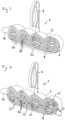
- the Figures 1 and 2 show schematically a device 1 for receiving a toilet cleaning agent in gel form, not shown in the figures.
- the device 1 has a housing 2 that is divided into a first housing part 6 and a second housing part 8.
- the device 1 also has a fastening device 4 in the form of a hook with which the device 1 can be hung in a toilet bowl.
- the housing 2 is particularly suitable for holding a gel toilet cleaning agent.
- a gel toilet cleaning agent for example, it can be designed to be transparent in order to make a colored toilet cleaning agent visible therein.
- the first housing part 6 is designed as a receptacle for the toilet cleaning agent and, in the embodiment shown, has four chambers 10, which can be partially connected to one another and are at least partially separated from one another by intermediate walls 18. The chambers are exposed at a main opening 12 of the first housing part 6.
- the main opening 12 is covered by the second housing part 8. Apart from the main opening 12, the first housing part 6 is designed to be completely closed.
- the second housing part 8 has a plurality of flushing openings 20 designed as openings.
- the sum of the cross-sectional areas of the flushing openings is less than the cross-sectional area of the main opening 12.
- the second housing part 8 is plugged onto the first housing part 6 and is connected to it in a stable but possibly also detachable manner.
- the flushing openings 20 are covered by a gas-tight and/or water vapor-tight cover 24 before the device 1 is put into use locked.
- a tab 26 the cover 24, which is designed, for example, as a film, can be removed from the second housing part 8, so that the flushing openings 20 are released and the toilet cleaning agent arranged in the housing 2 is accessible to water penetrating through the flushing openings 20.
- the device 1 is designed such that in a use position in which the device 1 has been suspended in a toilet bowl by means of the fastening device 4, the main opening 12 faces a wall of the toilet bowl.
- the second housing part 8 thus lies on a rear side 16 of the device 1, while the fastening device 4 is arranged on a front side 14 in the embodiment shown.
- This has the advantage that the water flowing down the wall of the toilet bowl can be directed particularly well through the flushing openings 20 into the chambers 10 during a flushing process.
- the in the Figures 1 and 2 Device 1 shown has a curved shape in at least one dimension, which therefore partially follows the shape of the toilet bowl. This enables the toilet cleaning agent to be rinsed out particularly efficiently and evenly.
- the cover 24 may be transparent to make the toilet cleaning agent and/or the second housing part 8 visible. This can be particularly advantageous if an aesthetic effect is to be achieved through the use of a colored toilet cleaning agent and/or through a specific arrangement and design of the flush openings 20, which should already be visible when the device 1 is still provided with the cover 24.
- Figure 3 shows a further embodiment of the device 1, which differs from that in Figure 1 shown differs in that the second housing part 8 has a water guide element 22, which is arranged below or in the middle of the flushing openings 20 and protrudes from the second housing part 8 in order to guide flushing water increasingly into the flushing openings 20 during operation.
- the second housing part 8 has a water guide element 22, which is arranged below or in the middle of the flushing openings 20 and protrudes from the second housing part 8 in order to guide flushing water increasingly into the flushing openings 20 during operation.
- Figure 4 shows a further embodiment of the device 1, which differs from that in Figure 1 shown in that the cover 24 has several parts, here designated 24 'and 24", which can be removed separately from one another and which are formed, for example, by several layers of film.
- a user can use the device 1 depending on the desired cleaning strength, choose whether it only removes a first film and thus "activates" the product, thereby releasing a number of flushing openings, or whether it removes at least one or more additional films and thus releasing further flushing openings and thus for a stronger cleaning effect ensures a higher flushing rate.
- a film 24 ' which covers most of the flushing openings 20 in a gas-tight and/or water vapor-tight manner, is removed by pulling on the tab 26.
- the further film 24" is also removed, which only covers the film underneath Separation 29 arranged flushing openings 20 covers, namely the two inner flushing openings of the bottom row. In this way, a user can easily dose the effect of the toilet cleaning agent and increase it by removing the film 24".
- the covers 24 ', 24" are designed as two adjacent areas of the same film, separated from each other by a perforation. Alternatively, however, they could also be designed as film layers arranged one above the other. Such an embodiment is in Figure 12 shown.
- FIGS. 5 and 6 show further embodiments of the device 1, which differ from that in Figure 4 shown in that all of the lowest flushing openings 20 are only released by removing the film 24". As a result, if the film 24" is not removed, a pool will form within the device 1, since water cannot drain completely. However, depending on the type of cleaning agent, this can be beneficial.
- the embodiment shown additionally has a water-conducting element 22.
- the Figures 7 and 8 show a further embodiment of the device 1 for holding a toilet cleaning agent. This differs from that in the Figures 1 and 2 shown embodiment in that the second housing part 8, in addition to the element having the flushing openings 20, also has a flap 28, which is connected to the remaining second housing part 8 via a hinge 30.
- the hinge 30, shown only schematically, can be designed, for example, as a film hinge.
- the flap 28 can be used to close the flushing openings 20 before use. However, since it is often difficult to make this closure gas-tight and/or water vapor-tight, a film can be arranged as a cover over the closed flap 28 before the device 1 is used, as shown in FIG Figures 1 and 2 is shown. However, the flap 28 serves additionally or primarily as a water-conducting element 22.
- a mechanical operative connection can exist between the flap 28 and the second housing part 8, such that the second housing part 8 is bent inwards into the housing 2 when the flap 28 is closed and protrudes slightly from it when the flap 28 is opened. This makes it possible to design the flap 28 flush with an edge of the first housing part 6, so that a cover 24 can be easily attached over the flap 28.
- the second housing part 8 in this embodiment is plugged onto the intermediate walls 18 of the first housing part 2 at several fastening points P. This is a particularly simple and stable type of attachment.
- FIGS 9 and 10 show a further embodiment of the device 1 for holding a toilet cleaning agent. This differs from those in the Figures 1 to 8 shown embodiments in that a cover 24 is arranged on the second housing part 8, which has a closure element 32 in the form of a “plug seal” with a grip tab 34. To put the device 1 into use, the user pulls on a handle tab 34 to remove the closure element 32. This will, as in Figure 10 shown, an underlying second housing part 8 with flushing openings not shown in the figures is exposed.
- FIG. 11 An alternative embodiment is in Figure 11 shown.
- the opening in the cover 24 created by removing the closure element 32 represents the common flushing opening for all chambers 10 of the device 1.
- the cover 24 is also the second housing part 8.
- several cutouts 25 are provided in the lower region of the second housing part 8, which form deep flushing openings after the cover 24 has been removed and thus prevent pool formation.
- FIG 12 shows an embodiment of the device 1, in which the cover is formed by two foil layers 24' and 24", which are shown partially open for better understanding.
- the first cover 24' covers the entire main opening 12 and forms a water vapor and gas-tight seal . It can be removed when the device is used by pulling on the tab 26.
- the second cover 24" is formed by a film layer arranged under the first cover 24' and has a number of openings which form flushing openings 20. This cover 24" can also be removed by pulling on a tab (not shown). If the cover 24" is also removed, a grid structure 31 is released which has openings which also form flushing openings 20'.
- the total area of the flushing openings 20' is larger than the total area of the flushing openings 20, for example at least twice as large. Thus, when the cover 24" is removed, significantly more cleaning agent is typically rinsed out than when the cover 24" is not removed.
- the 24" cover therefore provides a boost function.
- the grid structure 31 can also be formed by a film layer or in another way.
- FIGS. 13 to 17 show schematically several views of devices 1 according to different embodiments of the invention.
- a view of the back 16, a first cross-sectional view and a second cross-sectional view are shown. It can be seen that the contour of the second housing part 8 follows the shape of the main opening 12, which it covers. In particular, the second housing part 8 is fitted into the main opening 12.
- Figure 13 shows an embodiment of the device 1, which is essentially the one in the Figures 1 and 2 corresponds to shown.
- a cover 24 is attached to the edge of the first housing part.
- FIG 14 shows a further embodiment of the device 1, which differs from that in Figure 7 shown in that the flushing openings 20 are closed by flaps 36 in a closed state before the device 1 is used, each flushing opening having its own flap 36.
- Figure 15 shows the device 1 according to Figure 14 in the open state.
- the cover 24 is removed and the flaps 36 are open. These open automatically when the cover 24 is removed because they are under a corresponding pretension and act as water-conducting elements when open.
- FIGS 16 and 17 show a further embodiment of the device 1, which differs from that in the Figures 13 to 15 shown differs in that the flushing openings 20 have no flaps, but the second housing part 8 has a water-conducting element 38 projecting from the surface of the second housing part 8 in front of each chamber 10.
- the in Figure 16 When closed before use, the in Figure 16 is shown, the main opening 12 is closed gas-tight and/or water vapor-tight with a cover 24. If this is removed, the second housing part 8 springs into the in Figure 17 position shown in which the water guiding elements 38 protrude beyond the main opening 12. This has the advantage that the spring-loaded water-guiding elements 38 in the non-activated position allow the main opening 12 to be covered with the gas-tight and/or water-vapor-tight cover 24, which would not be easy to implement with excellent water-guiding elements 38.
Landscapes
- Health & Medical Sciences (AREA)
- Public Health (AREA)
- Epidemiology (AREA)
- Life Sciences & Earth Sciences (AREA)
- Engineering & Computer Science (AREA)
- Hydrology & Water Resources (AREA)
- Water Supply & Treatment (AREA)
- Bidet-Like Cleaning Device And Other Flush Toilet Accessories (AREA)
Applications Claiming Priority (2)
| Application Number | Priority Date | Filing Date | Title |
|---|---|---|---|
| DE102018222048.4A DE102018222048A1 (de) | 2018-12-18 | 2018-12-18 | Vorrichtung zur Aufnahme eines Toilettenreinigungsmittels |
| PCT/EP2019/082113 WO2020126297A1 (de) | 2018-12-18 | 2019-11-21 | Vorrichtung zur aufnahme eines toilettenreinigungsmittels |
Publications (2)
| Publication Number | Publication Date |
|---|---|
| EP3899152A1 EP3899152A1 (de) | 2021-10-27 |
| EP3899152B1 true EP3899152B1 (de) | 2024-01-03 |
Family
ID=68733024
Family Applications (1)
| Application Number | Title | Priority Date | Filing Date |
|---|---|---|---|
| EP19812935.5A Active EP3899152B1 (de) | 2018-12-18 | 2019-11-21 | Vorrichtung zur aufnahme eines toilettenreinigungsmittels |
Country Status (6)
| Country | Link |
|---|---|
| EP (1) | EP3899152B1 (pl) |
| CN (1) | CN113195840B (pl) |
| DE (1) | DE102018222048A1 (pl) |
| ES (1) | ES2971311T3 (pl) |
| PL (1) | PL3899152T3 (pl) |
| WO (1) | WO2020126297A1 (pl) |
Families Citing this family (1)
| Publication number | Priority date | Publication date | Assignee | Title |
|---|---|---|---|---|
| DE102019215652A1 (de) * | 2019-10-11 | 2021-04-15 | Henkel Ag & Co. Kgaa | Vorrichtung zur Aufnahme eines Toilettenreinigungsmittels, sowie Herstellungsverfahren dazu |
Family Cites Families (12)
| Publication number | Priority date | Publication date | Assignee | Title |
|---|---|---|---|---|
| DE1850791U (de) * | 1961-07-12 | 1962-04-26 | Guenter Dirker | Klosettbecken. |
| DE1815734A1 (de) * | 1967-12-22 | 1969-07-24 | Levey Robert Foye | Vorrichtung zum Speichern und Abgeben von Chemikalien in einen periodisch entleerten Wasserbehaelter od.dgl. |
| GB1219200A (en) * | 1968-05-29 | 1971-01-13 | Reckitt & Colmann Prod Ltd | Improvements in or relating to dispensing containers for use in flushing cisterns |
| NL6808754A (pl) * | 1968-06-21 | 1969-12-23 | ||
| JP2565720B2 (ja) * | 1987-09-30 | 1996-12-18 | 小林製薬株式会社 | 水洗トイレ用薬剤供給具 |
| DE19741283B4 (de) * | 1997-09-19 | 2006-10-12 | Buck- Chemie Gmbh | Vorrichtung zur Abgabe von Zusatzstoffen an das Spülwasser in Toilettenschüsseln |
| CN2544018Y (zh) * | 2002-04-24 | 2003-04-09 | 范发荣 | 吸盘式分注器 |
| FR2850407A1 (fr) * | 2003-01-27 | 2004-07-30 | Andre Cluzel | Dispositif de surete associe a un support de produit fixe au-dessus d'un reservoir telle une cuvette de w-c et support de produit adapte |
| DE102009012383A1 (de) * | 2009-03-09 | 2010-09-23 | Federal-Mogul Sealing Systems Gmbh | Temperatur-Schwingungsentkoppelelement |
| US10344462B2 (en) * | 2014-09-08 | 2019-07-09 | S. C. Johnson & Son, Inc. | Toilet rimblock and method of making such rimblock |
| DE102015110123A1 (de) | 2015-06-24 | 2016-12-29 | Buck Service Gmbh | Vorrichtung zur Aufnahme eines Toilettenreinigungsmittels |
| US10669705B2 (en) * | 2016-07-05 | 2020-06-02 | Willert Home Products, Inc. | Toilet bowl treatment apparatus and method of making same |
-
2018
- 2018-12-18 DE DE102018222048.4A patent/DE102018222048A1/de not_active Withdrawn
-
2019
- 2019-11-21 EP EP19812935.5A patent/EP3899152B1/de active Active
- 2019-11-21 CN CN201980083181.XA patent/CN113195840B/zh active Active
- 2019-11-21 ES ES19812935T patent/ES2971311T3/es active Active
- 2019-11-21 PL PL19812935.5T patent/PL3899152T3/pl unknown
- 2019-11-21 WO PCT/EP2019/082113 patent/WO2020126297A1/de not_active Ceased
Also Published As
| Publication number | Publication date |
|---|---|
| CN113195840A (zh) | 2021-07-30 |
| ES2971311T3 (es) | 2024-06-04 |
| CN113195840B (zh) | 2024-03-08 |
| PL3899152T3 (pl) | 2024-05-13 |
| DE102018222048A1 (de) | 2020-06-18 |
| EP3899152A1 (de) | 2021-10-27 |
| WO2020126297A1 (de) | 2020-06-25 |
Similar Documents
| Publication | Publication Date | Title |
|---|---|---|
| EP0370265B1 (de) | Zigaretten-Packung, insbesondere Klappschachtel | |
| DE2746118C2 (de) | Halter für auswechselbare Informationsträger in Streifenform | |
| EP1344500B1 (de) | Mehrkomponenten-Mischkapsel, insbesondere für Dentalzwecke | |
| DE1544098A1 (de) | Wasserentziehendes Element und seine Herstellung | |
| DE202014105771U1 (de) | Verpackungsbehälter | |
| DE3000474C2 (de) | Gehäuseförmige Abdeckung für einen einteiligen Akkumulator | |
| DE202004002477U1 (de) | Vorrichtung zum Schneiden von Obst und Gemüse, insbesondere Zwiebeln | |
| EP2806074A2 (de) | Haltevorrichtung und Spülvorrichtung zur Anbringung in einer Toilettenschüssel und Herstellung derselben Spülvorrichtung | |
| DE602004005226T2 (de) | Tablettenspender | |
| EP3899152B1 (de) | Vorrichtung zur aufnahme eines toilettenreinigungsmittels | |
| EP0224767A2 (de) | Vorrichtung zum Zusatz von Desinfektionsmitteln oder dergleichen in das Spülwasser eines WC | |
| DE69826377T2 (de) | Geschirrspülmaschine mit Vorrichtung zum Spenden von Waschmitteln und Waschverfahren | |
| DE19622033C1 (de) | Spender für Markierungsscheiben | |
| DE3502056A1 (de) | Wasserschutzbekleidung zum abdecken von karosserieteilen gegen von aussen in den fahrgastraum eindringende naesse | |
| EP2813612A1 (de) | Waschmaschine mit einem Waschmitteleinspülkasten | |
| DE102020007395A1 (de) | Filterpatrone und Filtervorrichtung | |
| DE202009018497U1 (de) | Dehn- und eindrückbare Schubladenbodenfolie | |
| EP1528904B1 (de) | Einweg-Hilfsmittel zum Urinieren | |
| WO2021094063A1 (de) | Wc-körbchen | |
| DE102009002303B4 (de) | Verfahren und Vorrichtung zum Dosieren von Reinigungsmitteln in einer Reinigungsmaschine | |
| DE102020107120A1 (de) | Blisterverpackung | |
| DE102004010733B3 (de) | Einlage für eine Katzentoilette | |
| AT1229U1 (de) | Insektenfalle | |
| EP2982267A2 (de) | Kosmetikbehälter | |
| DE102016102708B3 (de) | SD-Karten-Behälter |
Legal Events
| Date | Code | Title | Description |
|---|---|---|---|
| STAA | Information on the status of an ep patent application or granted ep patent |
Free format text: STATUS: UNKNOWN |
|
| STAA | Information on the status of an ep patent application or granted ep patent |
Free format text: STATUS: THE INTERNATIONAL PUBLICATION HAS BEEN MADE |
|
| PUAI | Public reference made under article 153(3) epc to a published international application that has entered the european phase |
Free format text: ORIGINAL CODE: 0009012 |
|
| STAA | Information on the status of an ep patent application or granted ep patent |
Free format text: STATUS: REQUEST FOR EXAMINATION WAS MADE |
|
| 17P | Request for examination filed |
Effective date: 20210520 |
|
| AK | Designated contracting states |
Kind code of ref document: A1 Designated state(s): AL AT BE BG CH CY CZ DE DK EE ES FI FR GB GR HR HU IE IS IT LI LT LU LV MC MK MT NL NO PL PT RO RS SE SI SK SM TR |
|
| DAV | Request for validation of the european patent (deleted) | ||
| DAX | Request for extension of the european patent (deleted) | ||
| P01 | Opt-out of the competence of the unified patent court (upc) registered |
Effective date: 20230530 |
|
| GRAP | Despatch of communication of intention to grant a patent |
Free format text: ORIGINAL CODE: EPIDOSNIGR1 |
|
| STAA | Information on the status of an ep patent application or granted ep patent |
Free format text: STATUS: GRANT OF PATENT IS INTENDED |
|
| INTG | Intention to grant announced |
Effective date: 20230721 |
|
| GRAS | Grant fee paid |
Free format text: ORIGINAL CODE: EPIDOSNIGR3 |
|
| GRAA | (expected) grant |
Free format text: ORIGINAL CODE: 0009210 |
|
| STAA | Information on the status of an ep patent application or granted ep patent |
Free format text: STATUS: THE PATENT HAS BEEN GRANTED |
|
| AK | Designated contracting states |
Kind code of ref document: B1 Designated state(s): AL AT BE BG CH CY CZ DE DK EE ES FI FR GB GR HR HU IE IS IT LI LT LU LV MC MK MT NL NO PL PT RO RS SE SI SK SM TR |
|
| REG | Reference to a national code |
Ref country code: GB Ref legal event code: FG4D Free format text: NOT ENGLISH |
|
| REG | Reference to a national code |
Ref country code: CH Ref legal event code: EP |
|
| REG | Reference to a national code |
Ref country code: DE Ref legal event code: R096 Ref document number: 502019010316 Country of ref document: DE |
|
| REG | Reference to a national code |
Ref country code: IE Ref legal event code: FG4D Free format text: LANGUAGE OF EP DOCUMENT: GERMAN |
|
| REG | Reference to a national code |
Ref country code: LT Ref legal event code: MG9D |
|
| REG | Reference to a national code |
Ref country code: NL Ref legal event code: MP Effective date: 20240103 |
|
| REG | Reference to a national code |
Ref country code: ES Ref legal event code: FG2A Ref document number: 2971311 Country of ref document: ES Kind code of ref document: T3 Effective date: 20240604 |
|
| PG25 | Lapsed in a contracting state [announced via postgrant information from national office to epo] |
Ref country code: NL Free format text: LAPSE BECAUSE OF FAILURE TO SUBMIT A TRANSLATION OF THE DESCRIPTION OR TO PAY THE FEE WITHIN THE PRESCRIBED TIME-LIMIT Effective date: 20240103 |
|
| PG25 | Lapsed in a contracting state [announced via postgrant information from national office to epo] |
Ref country code: NL Free format text: LAPSE BECAUSE OF FAILURE TO SUBMIT A TRANSLATION OF THE DESCRIPTION OR TO PAY THE FEE WITHIN THE PRESCRIBED TIME-LIMIT Effective date: 20240103 |
|
| PG25 | Lapsed in a contracting state [announced via postgrant information from national office to epo] |
Ref country code: IS Free format text: LAPSE BECAUSE OF FAILURE TO SUBMIT A TRANSLATION OF THE DESCRIPTION OR TO PAY THE FEE WITHIN THE PRESCRIBED TIME-LIMIT Effective date: 20240503 |
|
| PG25 | Lapsed in a contracting state [announced via postgrant information from national office to epo] |
Ref country code: LT Free format text: LAPSE BECAUSE OF FAILURE TO SUBMIT A TRANSLATION OF THE DESCRIPTION OR TO PAY THE FEE WITHIN THE PRESCRIBED TIME-LIMIT Effective date: 20240103 |
|
| PG25 | Lapsed in a contracting state [announced via postgrant information from national office to epo] |
Ref country code: GR Free format text: LAPSE BECAUSE OF FAILURE TO SUBMIT A TRANSLATION OF THE DESCRIPTION OR TO PAY THE FEE WITHIN THE PRESCRIBED TIME-LIMIT Effective date: 20240404 |
|
| PG25 | Lapsed in a contracting state [announced via postgrant information from national office to epo] |
Ref country code: HR Free format text: LAPSE BECAUSE OF FAILURE TO SUBMIT A TRANSLATION OF THE DESCRIPTION OR TO PAY THE FEE WITHIN THE PRESCRIBED TIME-LIMIT Effective date: 20240103 Ref country code: RS Free format text: LAPSE BECAUSE OF FAILURE TO SUBMIT A TRANSLATION OF THE DESCRIPTION OR TO PAY THE FEE WITHIN THE PRESCRIBED TIME-LIMIT Effective date: 20240403 |
|
| PG25 | Lapsed in a contracting state [announced via postgrant information from national office to epo] |
Ref country code: RS Free format text: LAPSE BECAUSE OF FAILURE TO SUBMIT A TRANSLATION OF THE DESCRIPTION OR TO PAY THE FEE WITHIN THE PRESCRIBED TIME-LIMIT Effective date: 20240403 Ref country code: NO Free format text: LAPSE BECAUSE OF FAILURE TO SUBMIT A TRANSLATION OF THE DESCRIPTION OR TO PAY THE FEE WITHIN THE PRESCRIBED TIME-LIMIT Effective date: 20240403 Ref country code: LT Free format text: LAPSE BECAUSE OF FAILURE TO SUBMIT A TRANSLATION OF THE DESCRIPTION OR TO PAY THE FEE WITHIN THE PRESCRIBED TIME-LIMIT Effective date: 20240103 Ref country code: IS Free format text: LAPSE BECAUSE OF FAILURE TO SUBMIT A TRANSLATION OF THE DESCRIPTION OR TO PAY THE FEE WITHIN THE PRESCRIBED TIME-LIMIT Effective date: 20240503 Ref country code: HR Free format text: LAPSE BECAUSE OF FAILURE TO SUBMIT A TRANSLATION OF THE DESCRIPTION OR TO PAY THE FEE WITHIN THE PRESCRIBED TIME-LIMIT Effective date: 20240103 Ref country code: GR Free format text: LAPSE BECAUSE OF FAILURE TO SUBMIT A TRANSLATION OF THE DESCRIPTION OR TO PAY THE FEE WITHIN THE PRESCRIBED TIME-LIMIT Effective date: 20240404 Ref country code: BG Free format text: LAPSE BECAUSE OF FAILURE TO SUBMIT A TRANSLATION OF THE DESCRIPTION OR TO PAY THE FEE WITHIN THE PRESCRIBED TIME-LIMIT Effective date: 20240103 |
|
| PG25 | Lapsed in a contracting state [announced via postgrant information from national office to epo] |
Ref country code: PT Free format text: LAPSE BECAUSE OF FAILURE TO SUBMIT A TRANSLATION OF THE DESCRIPTION OR TO PAY THE FEE WITHIN THE PRESCRIBED TIME-LIMIT Effective date: 20240503 |
|
| PG25 | Lapsed in a contracting state [announced via postgrant information from national office to epo] |
Ref country code: SE Free format text: LAPSE BECAUSE OF FAILURE TO SUBMIT A TRANSLATION OF THE DESCRIPTION OR TO PAY THE FEE WITHIN THE PRESCRIBED TIME-LIMIT Effective date: 20240103 Ref country code: PT Free format text: LAPSE BECAUSE OF FAILURE TO SUBMIT A TRANSLATION OF THE DESCRIPTION OR TO PAY THE FEE WITHIN THE PRESCRIBED TIME-LIMIT Effective date: 20240503 Ref country code: LV Free format text: LAPSE BECAUSE OF FAILURE TO SUBMIT A TRANSLATION OF THE DESCRIPTION OR TO PAY THE FEE WITHIN THE PRESCRIBED TIME-LIMIT Effective date: 20240103 |
|
| REG | Reference to a national code |
Ref country code: DE Ref legal event code: R097 Ref document number: 502019010316 Country of ref document: DE |
|
| PG25 | Lapsed in a contracting state [announced via postgrant information from national office to epo] |
Ref country code: DK Free format text: LAPSE BECAUSE OF FAILURE TO SUBMIT A TRANSLATION OF THE DESCRIPTION OR TO PAY THE FEE WITHIN THE PRESCRIBED TIME-LIMIT Effective date: 20240103 |
|
| PG25 | Lapsed in a contracting state [announced via postgrant information from national office to epo] |
Ref country code: SM Free format text: LAPSE BECAUSE OF FAILURE TO SUBMIT A TRANSLATION OF THE DESCRIPTION OR TO PAY THE FEE WITHIN THE PRESCRIBED TIME-LIMIT Effective date: 20240103 |
|
| PG25 | Lapsed in a contracting state [announced via postgrant information from national office to epo] |
Ref country code: EE Free format text: LAPSE BECAUSE OF FAILURE TO SUBMIT A TRANSLATION OF THE DESCRIPTION OR TO PAY THE FEE WITHIN THE PRESCRIBED TIME-LIMIT Effective date: 20240103 |
|
| PG25 | Lapsed in a contracting state [announced via postgrant information from national office to epo] |
Ref country code: SK Free format text: LAPSE BECAUSE OF FAILURE TO SUBMIT A TRANSLATION OF THE DESCRIPTION OR TO PAY THE FEE WITHIN THE PRESCRIBED TIME-LIMIT Effective date: 20240103 |
|
| PG25 | Lapsed in a contracting state [announced via postgrant information from national office to epo] |
Ref country code: SM Free format text: LAPSE BECAUSE OF FAILURE TO SUBMIT A TRANSLATION OF THE DESCRIPTION OR TO PAY THE FEE WITHIN THE PRESCRIBED TIME-LIMIT Effective date: 20240103 Ref country code: SK Free format text: LAPSE BECAUSE OF FAILURE TO SUBMIT A TRANSLATION OF THE DESCRIPTION OR TO PAY THE FEE WITHIN THE PRESCRIBED TIME-LIMIT Effective date: 20240103 Ref country code: RO Free format text: LAPSE BECAUSE OF FAILURE TO SUBMIT A TRANSLATION OF THE DESCRIPTION OR TO PAY THE FEE WITHIN THE PRESCRIBED TIME-LIMIT Effective date: 20240103 Ref country code: EE Free format text: LAPSE BECAUSE OF FAILURE TO SUBMIT A TRANSLATION OF THE DESCRIPTION OR TO PAY THE FEE WITHIN THE PRESCRIBED TIME-LIMIT Effective date: 20240103 Ref country code: DK Free format text: LAPSE BECAUSE OF FAILURE TO SUBMIT A TRANSLATION OF THE DESCRIPTION OR TO PAY THE FEE WITHIN THE PRESCRIBED TIME-LIMIT Effective date: 20240103 |
|
| PLBE | No opposition filed within time limit |
Free format text: ORIGINAL CODE: 0009261 |
|
| STAA | Information on the status of an ep patent application or granted ep patent |
Free format text: STATUS: NO OPPOSITION FILED WITHIN TIME LIMIT |
|
| 26N | No opposition filed |
Effective date: 20241007 |
|
| PG25 | Lapsed in a contracting state [announced via postgrant information from national office to epo] |
Ref country code: SI Free format text: LAPSE BECAUSE OF FAILURE TO SUBMIT A TRANSLATION OF THE DESCRIPTION OR TO PAY THE FEE WITHIN THE PRESCRIBED TIME-LIMIT Effective date: 20240103 |
|
| REG | Reference to a national code |
Ref country code: CH Ref legal event code: PL |
|
| PG25 | Lapsed in a contracting state [announced via postgrant information from national office to epo] |
Ref country code: MC Free format text: LAPSE BECAUSE OF FAILURE TO SUBMIT A TRANSLATION OF THE DESCRIPTION OR TO PAY THE FEE WITHIN THE PRESCRIBED TIME-LIMIT Effective date: 20240103 |
|
| PG25 | Lapsed in a contracting state [announced via postgrant information from national office to epo] |
Ref country code: LU Free format text: LAPSE BECAUSE OF NON-PAYMENT OF DUE FEES Effective date: 20241121 |
|
| REG | Reference to a national code |
Ref country code: CH Ref legal event code: PL |
|
| PG25 | Lapsed in a contracting state [announced via postgrant information from national office to epo] |
Ref country code: CH Free format text: LAPSE BECAUSE OF NON-PAYMENT OF DUE FEES Effective date: 20241130 |
|
| REG | Reference to a national code |
Ref country code: BE Ref legal event code: MM Effective date: 20241130 |
|
| PG25 | Lapsed in a contracting state [announced via postgrant information from national office to epo] |
Ref country code: FI Free format text: LAPSE BECAUSE OF FAILURE TO SUBMIT A TRANSLATION OF THE DESCRIPTION OR TO PAY THE FEE WITHIN THE PRESCRIBED TIME-LIMIT Effective date: 20240103 |
|
| PG25 | Lapsed in a contracting state [announced via postgrant information from national office to epo] |
Ref country code: BE Free format text: LAPSE BECAUSE OF NON-PAYMENT OF DUE FEES Effective date: 20241130 |
|
| PG25 | Lapsed in a contracting state [announced via postgrant information from national office to epo] |
Ref country code: IE Free format text: LAPSE BECAUSE OF NON-PAYMENT OF DUE FEES Effective date: 20241121 |
|
| PGFP | Annual fee paid to national office [announced via postgrant information from national office to epo] |
Ref country code: DE Payment date: 20251119 Year of fee payment: 7 |
|
| PGFP | Annual fee paid to national office [announced via postgrant information from national office to epo] |
Ref country code: GB Payment date: 20251121 Year of fee payment: 7 |
|
| PG25 | Lapsed in a contracting state [announced via postgrant information from national office to epo] |
Ref country code: AT Free format text: LAPSE BECAUSE OF NON-PAYMENT OF DUE FEES Effective date: 20241121 |
|
| PGFP | Annual fee paid to national office [announced via postgrant information from national office to epo] |
Ref country code: IT Payment date: 20251125 Year of fee payment: 7 |
|
| PGFP | Annual fee paid to national office [announced via postgrant information from national office to epo] |
Ref country code: FR Payment date: 20251126 Year of fee payment: 7 |
|
| REG | Reference to a national code |
Ref country code: AT Ref legal event code: MM01 Ref document number: 1646920 Country of ref document: AT Kind code of ref document: T Effective date: 20241121 |
|
| PGFP | Annual fee paid to national office [announced via postgrant information from national office to epo] |
Ref country code: TR Payment date: 20251117 Year of fee payment: 7 |
|
| PGFP | Annual fee paid to national office [announced via postgrant information from national office to epo] |
Ref country code: CZ Payment date: 20251113 Year of fee payment: 7 |
|
| PGFP | Annual fee paid to national office [announced via postgrant information from national office to epo] |
Ref country code: PL Payment date: 20251114 Year of fee payment: 7 |
|
| PGFP | Annual fee paid to national office [announced via postgrant information from national office to epo] |
Ref country code: ES Payment date: 20251229 Year of fee payment: 7 |
|
| PG25 | Lapsed in a contracting state [announced via postgrant information from national office to epo] |
Ref country code: HU Free format text: LAPSE BECAUSE OF FAILURE TO SUBMIT A TRANSLATION OF THE DESCRIPTION OR TO PAY THE FEE WITHIN THE PRESCRIBED TIME-LIMIT; INVALID AB INITIO Effective date: 20191121 |