EP3897301B1 - Aufblasbare luftmatratze mit internem stützsystem - Google Patents
Aufblasbare luftmatratze mit internem stützsystem Download PDFInfo
- Publication number
- EP3897301B1 EP3897301B1 EP19900094.4A EP19900094A EP3897301B1 EP 3897301 B1 EP3897301 B1 EP 3897301B1 EP 19900094 A EP19900094 A EP 19900094A EP 3897301 B1 EP3897301 B1 EP 3897301B1
- Authority
- EP
- European Patent Office
- Prior art keywords
- loop
- attachment strip
- panel
- air mattress
- internal support
- Prior art date
- Legal status (The legal status is an assumption and is not a legal conclusion. Google has not performed a legal analysis and makes no representation as to the accuracy of the status listed.)
- Active
Links
Images




Classifications
-
- A—HUMAN NECESSITIES
- A47—FURNITURE; DOMESTIC ARTICLES OR APPLIANCES; COFFEE MILLS; SPICE MILLS; SUCTION CLEANERS IN GENERAL
- A47C—CHAIRS; SOFAS; BEDS
- A47C27/00—Spring, stuffed or fluid mattresses or cushions specially adapted for chairs, beds or sofas
- A47C27/08—Fluid mattresses
- A47C27/081—Fluid mattresses of pneumatic type
- A47C27/083—Fluid mattresses of pneumatic type with pressure control, e.g. with pressure sensors
-
- A—HUMAN NECESSITIES
- A47—FURNITURE; DOMESTIC ARTICLES OR APPLIANCES; COFFEE MILLS; SPICE MILLS; SUCTION CLEANERS IN GENERAL
- A47C—CHAIRS; SOFAS; BEDS
- A47C27/00—Spring, stuffed or fluid mattresses or cushions specially adapted for chairs, beds or sofas
- A47C27/08—Fluid mattresses
- A47C27/087—Fluid mattresses with means for connecting opposite sides, e.g. internal ties or strips
-
- B—PERFORMING OPERATIONS; TRANSPORTING
- B29—WORKING OF PLASTICS; WORKING OF SUBSTANCES IN A PLASTIC STATE IN GENERAL
- B29C—SHAPING OR JOINING OF PLASTICS; SHAPING OF MATERIAL IN A PLASTIC STATE, NOT OTHERWISE PROVIDED FOR; AFTER-TREATMENT OF THE SHAPED PRODUCTS, e.g. REPAIRING
- B29C66/00—General aspects of processes or apparatus for joining preformed parts
- B29C66/01—General aspects dealing with the joint area or with the area to be joined
- B29C66/05—Particular design of joint configurations
- B29C66/10—Particular design of joint configurations particular design of the joint cross-sections
- B29C66/11—Joint cross-sections comprising a single joint-segment, i.e. one of the parts to be joined comprising a single joint-segment in the joint cross-section
- B29C66/112—Single lapped joints
- B29C66/1122—Single lap to lap joints, i.e. overlap joints
-
- B—PERFORMING OPERATIONS; TRANSPORTING
- B29—WORKING OF PLASTICS; WORKING OF SUBSTANCES IN A PLASTIC STATE IN GENERAL
- B29C—SHAPING OR JOINING OF PLASTICS; SHAPING OF MATERIAL IN A PLASTIC STATE, NOT OTHERWISE PROVIDED FOR; AFTER-TREATMENT OF THE SHAPED PRODUCTS, e.g. REPAIRING
- B29C66/00—General aspects of processes or apparatus for joining preformed parts
- B29C66/40—General aspects of joining substantially flat articles, e.g. plates, sheets or web-like materials; Making flat seams in tubular or hollow articles; Joining single elements to substantially flat surfaces
- B29C66/41—Joining substantially flat articles ; Making flat seams in tubular or hollow articles
- B29C66/43—Joining a relatively small portion of the surface of said articles
- B29C66/433—Casing-in, i.e. enclosing an element between two sheets by an outlined seam
-
- B—PERFORMING OPERATIONS; TRANSPORTING
- B29—WORKING OF PLASTICS; WORKING OF SUBSTANCES IN A PLASTIC STATE IN GENERAL
- B29C—SHAPING OR JOINING OF PLASTICS; SHAPING OF MATERIAL IN A PLASTIC STATE, NOT OTHERWISE PROVIDED FOR; AFTER-TREATMENT OF THE SHAPED PRODUCTS, e.g. REPAIRING
- B29C66/00—General aspects of processes or apparatus for joining preformed parts
- B29C66/40—General aspects of joining substantially flat articles, e.g. plates, sheets or web-like materials; Making flat seams in tubular or hollow articles; Joining single elements to substantially flat surfaces
- B29C66/47—Joining single elements to sheets, plates or other substantially flat surfaces
- B29C66/472—Joining single elements to sheets, plates or other substantially flat surfaces said single elements being substantially flat
- B29C66/4722—Fixing strips to surfaces other than edge faces
-
- B—PERFORMING OPERATIONS; TRANSPORTING
- B29—WORKING OF PLASTICS; WORKING OF SUBSTANCES IN A PLASTIC STATE IN GENERAL
- B29D—PRODUCING PARTICULAR ARTICLES FROM PLASTICS OR FROM SUBSTANCES IN A PLASTIC STATE
- B29D22/00—Producing hollow articles
- B29D22/02—Inflatable articles
-
- A—HUMAN NECESSITIES
- A47—FURNITURE; DOMESTIC ARTICLES OR APPLIANCES; COFFEE MILLS; SPICE MILLS; SUCTION CLEANERS IN GENERAL
- A47C—CHAIRS; SOFAS; BEDS
- A47C27/00—Spring, stuffed or fluid mattresses or cushions specially adapted for chairs, beds or sofas
- A47C27/08—Fluid mattresses
- A47C27/081—Fluid mattresses of pneumatic type
Definitions
- aspects of the present disclosure relate to systems and methods for providing internal support for an air mattress.
- Inflatable air mattresses are often filled with air, and when a load is set atop an air mattress, such as a user sitting or lying on the air mattress, the load can cause an increase in the internal pressure of the air mattress. In turn, such an increase in internal pressure can cause the air mattress to deform or distort in shape, such as by causing the walls of the air mattress to bow outwards or cause the body of the air mattress to shear and slant in one or more directions. Such distortions can create a sense of imbalance that can affect a user's comfort level when, for example, attempting to sleep on the inflated air mattress. Accordingly, to increase structural stability, some air mattress designs include internal structures attempting to inhibit such distortions. Some inflatable air mattresses may include an internal support system that includes one or more separate chambers.
- Some inflatable air mattresses may attempt to solve this problem by including apertures in some of the components of the internal structure, such as a mesh material, for example. But the use of mesh material can cause difficulties during manufacturing, such as attaching the mesh material to other portions of the air mattress.
- US 2017/0238718 A1 describes an inflatable product and an inflatable product fusing process.
- the inflatable product comprises an upper sheet, a lower sheet, pull straps provided therebetween, and upper and lower fixing sheets having one faces away from each other respectively joined with inner surfaces of the upper and lower sheets and one faces facing towards each other not joined.
- the present invention provides a inflatable air mattress and a method of manufacturing an inflatable air mattress as claimed in independent claims 1 and 9. Preferred features are set out in the dependent claims.
- the present disclosure can be understood more readily by reference to the following detailed description of examples included herein. Before the examples of the devices and methods according to the present disclosure are disclosed and described, it is to be understood that disclosed technology is not limited to the specific examples described within this disclosure. Numerous modifications and variations therein will be apparent to those skilled in the art and remain within the scope of the disclosure. It is also to be understood that the terminology used herein is for the purpose of describing specific examples only and is not intended to be limiting. Some examples of the disclosed technology will be described more fully hereinafter with reference to the accompanying drawings. This disclosed technology can, however, be embodied in many different forms and should not be construed as limited to the examples set forth therein.
- an inflatable air mattress having an internal support system for providing structural stability to the air mattress.
- an inflatable air mattress having an internal support system can include one or more loops of material, and each loop of material can be attached to a top panel and a bottom panel of the air mattress.
- the internal support structure described herein can prevent distortions in the shape or orientation of the air mattress and add stability and support to the structure of the air mattress.
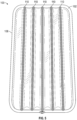
- FIGs. 1 and 2 illustrate an inflatable air mattress 100 having a top panel 102, a bottom panel 104, and one or more side panels 106 to form an airtight enclosure.
- the top panel 102, bottom panel 104, and one or more side panels 106 can be made of polypropylene, polyethylene, nylon, polyvinyl chloride (“PVC"), polytetrafluoroethylene (“PTFE”), plastic, rubber, or any other suitable material that is known in the art.
- the inflatable air mattress can be filled with air (or any gas) and used as a mattress, a pillow, or a cushion, for example.
- the inflatable air mattress 100 according to the invention includes a valve through which air can be pumped into the internal chamber of the air mattress 100 or can be released from the internal chamber of the air mattress 100.
- the inflatable air mattress 100 can include multiple internal support structures 110.
- the internal support structures 110 can extend across some of all of the width or length of the inflatable air mattress 100.
- the internal support structures 110 can extend across substantially all of the width or length of the air mattress 100.
- the internal support structures 110 can have a width that is substantially less than the width or length of the air mattress 100.
- the air mattress 100 can include one or more internal support structures 110 of a first size (e.g., having a width that is substantially the same distance as the width or length of the air mattress 100) and one or more internal support structures 110 of a second size (e.g., having a width that is substantially smaller distance than the width or length of the air mattress).
- One or more internal support structures 110 can be positioned substantially parallel to the width or length of the air mattress 100 (e.g., parallel to one or more side panels 106). Additionally or alternatively, one or more internal support structures 110 can be positioned diagonally with respect to the width or length of the air mattress 100 (e.g., parallel to one or more side panels 106). Additionally or alternatively, one or more internal support structures 110 can be positioned diagonally with respect to one or more side walls 106.
- each internal support structure 110 includes a length of material that is wrapped in a loop 312.
- the loop 312 can be made from any suitable material, such as made of polypropylene, polyethylene, nylon, PVC, PTFE, plastic, or rubber, for example.
- the loop can be made from a material having apertures.
- the loop 312 can made using a mesh material.
- Each internal support structure 110 is attached to the top panel 102 and the bottom panel 104. Alternatively or in addition, one or more internal support structures 110 is/are affixed to the internal surface of either the top panel 102 or bottom panel 104 by an attachment strip 314.
- An attachment strip 314 can be a piece of material (e.g., polypropylene, polyethylene, nylon, PVC, PTFE, plastic, rubber) that can be welded, glued, adhered, or otherwise attached to the internal surface of the top panel 102 or bottom panel 104 to secure a portion of the attachment strip 314 to the top panel 102 or bottom panel 104.
- a portion of the internal support structure 110 can be attached to one or more internal surfaces of a side panel 106, a portion of the internal support structure 110 can be attached to one or more adjacent internal support structures 110, and/or a portion of the internal support structure 110 can be attached to a side panel 106.
- a portion of the internal support structure 110 can be attached to one or more adjacent internal support structures 110 and another portion of the internal support structure 110 can be attached to a side panel 106.
- the loop 312 has two ends that overlap one another. As shown in FIG. 3 , an attachment strip or side strip 316 is positioned proximate the overlapping ends of the loop 312.
- the side strip 316 can be a piece of material (e.g., polypropylene, polyethylene, nylon, PVC, PTFE, plastic, rubber). Alternatively, the side strip 316 can be the same material as the attachment strips 314. In other examples, the overlapping ends of the loop 312 can be welded, glued, adhered, or otherwise attached to the side strip 316.
- the internal support structure 110 of the inflatable air mattress according to the invention includes a loop 312 having two attachment strips 314 positioned within the loop 312 to affix the loop 312 to a top panel and a bottom panel 104, as well as one side strip 316 to secure the overlapping ends of the loop 312 to one another.
- the side strip 316 can be positioned outside the loop 312 and adjacent to the overlapping ends of the loop 312, the side strip 316 can be positioned within the loop 312 and adjacent to the overlapping ends of the loop 312, and/or the side strip 316 can be positioned between the overlapping ends of the loop 312.
- the disclosed technology can include a second side strip 316.
- a first side strip 316 can be positioned outside the loop 312 and adjacent the overlapping ends of the loop 312, and a second side strip can be positioned within the loop 312 and adjacent to the overlapping ends of the loop 312, as well as adjacent to the first side strip 316. That is, the overlapping ends of the loop 312 can be sandwiched between two side strips 316, and the two side strips 316 can be welded, glued, adhered, or otherwise attached one another such that the overlapping ends are secured.
- a side strip 316 may not be included.
- the overlapping ends of the loop 312 can be positioned proximate the top panel 102 or the bottom panel 104 such that an attachment strip 314 can simultaneously affix the loop 312 to the top or bottom panel 102, 104 and secure the overlapping ends of the loop 312 to one another.
- an attachment strip 314 can be positioned within the loop 312 and adjacent to the overlapping ends of the loop 312, as well as adjacent to the top or bottom panel 102, 104.
- an attachment strip 314 can be positioned between the overlapping ends of the loop 312 and adjacent to the top or bottom panel 102, 104.
- a second attachment strip 314 can be positioned within the loop 312 and opposite the first attachment strip 314 that is securing the overlapping ends of the loop 312 together such the second attachment strip 314 can secure the loop 312 to the top or bottom panel 102, 104 (i.e., the panel opposite the panel to which the first attachment strip 314 is securing the loop 312).
- Internal support structures 110 omitting a side strip 316 can be more difficult to manufacture as compared to internal support structures 110 including one or more side strips 316, but internal support structures 110 omitting a side strip 316 can enable an air mattress 100 to be constructed using less material.
- an internal support structure 110 can include two side strips 316.
- a portion of the loop 312 opposite the overlapping ends of the loop 312 can also be welded, glued, adhered, or otherwise attached to the side strip 316, which can cause the loop 312 to "pinch" together at the attachment point to the side strip 316 (i.e., the width of the loop 312 can decrease at or near the location that the loop 312 is attached to the side strip 316).
- a first side strip 316 can be positioned outside the loop 312 and adjacent the overlapping ends of the loop 312, and a second side strip 316 can be positioned outside the loop 312 and adjacent a portion of the loop 312 opposite the overlapping ends of the loop 312.
- first side strip 316 can be positioned between the overlapping ends of the loop 312, and a second side strip 316 can be positioned outside the loop 312 and adjacent to a portion of the loop 312 opposite the overlapping ends of the loop 312.
- first and second side strips 316 can be welded, glued, adhered, or otherwise attached to one another, which can cause the overlapping ends of the loop to become secured together and can cause the width of the loop 312 to "pinch" together at or near the location of the first and second side strips 316.
- An internal support structure 110 can "pinch" together while including only a single side strip 316.
- the side strip 316 can be positioned outside the loop 312 and adjacent to the overlapping ends of the loop.
- the side strip 316 can be positioned outside the loop 312 and adjacent to a portion of the loop 312 opposite the overlapping ends of the loop 312.
- the side strip 316 can be positioned between the overlapping ends of the loop 312. Regardless, each of the overlapping ends, the portion of the loop 312 opposite the overlapping ends, and the side strip 316 can be welded, glued, adhered, or otherwise attached together.
- the loop 312 can be made from a material that can be welded, glued, adhered, or otherwise attached to itself and/or welded, glued, adhered, or otherwise attached to the top panel 102, bottom panel 104, and/or side panel 106.
- an internal support structure 110 may not include an attachment strip 314 or a side strip 316 but can still be affixed to the top panel 102, bottom panel 104, side panel 106, and/or an adjacent internal support structure 110.
- the overlapping ends of the loop can be secured directly to one another (i.e., without an attachment strip 314 or a side strip 316) by welding, gluing, adhering, or otherwise attaching the overlapping ends together.
- a "pinch" can be created by welding, gluing, adhering, or otherwise attaching the overlapping ends to a portion of the loop 312 opposite the overlapping ends.
- FIGs. 5-12 depict various examples of the disclosed technology.
- FIGs. 5-8 depict an air mattress 100 including five internal support structures 110 that extend along a large portion of the length of the air mattress 100.
- the inflatable air mattress according to the invention (such as the example air mattress shown in FIGs. 5-8 and as most clearly shown in FIGs. 7 and 8 ) includes a first side strip 316 that can be positioned outside the loop 312 and proximate the overlapping ends of the loop 312, and a second side strip 316 that can be positioned within the loop 312 and proximate the overlapping ends.
- the first and second side strips 316 can then be welded, glued, adhered, or otherwise attached to one another, causing the overlapping ends to close the loop.
- FIGs. 9-12 depict an air cushion representative of an air mattress, in accordance with some examples of the disclosed technology.
- the example air cushion depicted includes a single internal support structure 110, which includes a first side strip 316 positioned outside the loop 312 and proximate the overlapping ends and a second side strip 316 a second side strip 316 can be positioned outside the loop 312 and adjacent a portion of the loop 312 opposite the overlapping ends of the loop 312, as discussed above.
- attachment of the first side strip 316 to the second side strip 316 causes the loop 312 to "pinch" together at or near the first and second side strips 316.
- a single support structure 110 is shown, it is understood that a plurality of similar support structures 100 could be used in an air mattress, according to the disclosed technology.
Landscapes
- Engineering & Computer Science (AREA)
- Mechanical Engineering (AREA)
- Mattresses And Other Support Structures For Chairs And Beds (AREA)
Claims (14)
- Aufblasbare Luftmatratze (100), umfassend:eine obere Bahn (102);eine untere Bahn (104);eine oder mehrere Seitenbahnen (106), die an der oberen Bahn (102) und der unteren Bahn (104) befestigt sind, um eine im Wesentlichen luftdichte Hülle zu bilden;ein Ventil, das konfiguriert ist, um den Ein- und Austritt von Luft aus der im Wesentlichen luftdichten Hülle zu steuern; undeine innere Stützstruktur (110), die umfasst:ein Stück Material mit einem ersten Ende und einem zweiten Ende, wobei das erste Ende mit dem zweiten Ende überlappt, um zu bewirken, dass das Stück Material eine Schlaufe (312) mit einer Innenfläche und einer Außenfläche bildet;einen ersten Befestigungsstreifen (314), der in der Schlaufe (312) positioniert und an der oberen Bahn (102) befestigt ist, so dass die Außenfläche der Schlaufe (312) an einer Innenfläche der oberen Bahn anliegt;einen zweiten Befestigungsstreifen (314), der in der Schlaufe (312) positioniert und an der unteren Bahn (104) befestigt ist, so dass die Außenfläche der Schlaufe (312) an einer Innenfläche der unteren Bahn anliegt; undeinen dritten Befestigungsstreifen (316), der am ersten Ende und am zweiten Ende befestigt ist, um die überlappenden ersten und zweiten Enden aneinander zu befestigen.
- Aufblasbare Luftmatratze nach Anspruch 1, bei der der dritte Befestigungsstreifen (316) außerhalb der Schlaufe (312) angeordnet ist.
- Aufblasbare Luftmatratze nach Anspruch 1, bei der der dritte Befestigungsstreifen (316) innerhalb der Schlaufe (312) angeordnet ist.
- Aufblasbare Luftmatratze nach Anspruch 1, die ferner einen vierten Befestigungsstreifen (316) umfasst, der in der Nähe des ersten und zweiten Endes angeordnet und an dem dritten Befestigungsstreifen (316) befestigt ist.
- Aufblasbare Luftmatratze nach Anspruch 4, bei der der vierte Befestigungsstreifen (316) innerhalb der Schlaufe (312) angeordnet ist.
- Aufblasbare Luftmatratze nach Anspruch 4, bei der der vierte Befestigungsstreifen (316) außerhalb der Schlaufe (312) und in der Nähe eines Abschnitts der Schlaufe gegenüber dem ersten und zweiten Ende angeordnet ist.
- Aufblasbare Luftmatratze nach Anspruch 1, bei der der dritte Befestigungsstreifen (316) innerhalb der Schlaufe (312) positioniert und an einer Seitenbahn (106) der ein oder mehreren Seitenbahnen befestigt ist.
- Aufblasbare Luftmatratze nach Anspruch 1, bei der die innere Stützstruktur (110) eine erste innere Stützstruktur ist und die aufblasbare Luftmatratze ferner eine zweite innere Stützstruktur umfasst,
wobei optional die Schlaufe (312) der ersten inneren Stützstruktur (110) eine erste Schlaufe ist, der dritte Befestigungsstreifen (316) innerhalb der ersten Schlaufe positioniert ist und ein vierter Befestigungsstreifen (316) innerhalb einer zweiten Schlaufe der zweiten inneren Stützstruktur positioniert ist, wobei der vierte Befestigungsstreifen (316) an dem dritten Befestigungsstreifen (316) befestigt ist. - Verfahren zur Herstellung einer aufblasbaren Luftmatratze, wobei das Verfahren umfasst:Bereitstellen einer ersten Bahn (102);Bereitstellen einer zweiten Bahn (104);Ausbilden einer inneren Stützstruktur (110) zwischen der ersten und der zweiten Bahn (102, 104) durch:Bilden einer Schlaufe (312) mit einem Stück Material, indem ein erstes Ende des Stücks Material mit einem zweiten Ende des Stücks Material überlappt wird, wobei die Schlaufe (312) eine Innenfläche und eine Außenfläche aufweist;Bereitstellen eines ersten (314), eines zweiten (314) und eines dritten (316) Befestigungsstreifens;Positionieren des ersten Befestigungsstreifens (314) und des zweiten Befestigungsstreifens (314) innerhalb der Schlaufe (312);Befestigen des ersten Befestigungsstreifens (314) an einer Innenfläche der ersten Bahn (102), so dass die Außenfläche der Schlaufe (312) an der Innenfläche der ersten Bahn anliegt;Befestigen des zweiten Befestigungsstreifens (314) an einer Innenfläche der zweiten Bahn (104), so dass die Außenfläche der Schlaufe (312) an der Innenfläche der zweiten Bahn anliegt;Verbinden des ersten Endes mit dem zweiten Ende durch den dritten Befestigungsstreifen (316), um die überlappenden ersten und zweiten Enden aneinander zu befestigen;Anbringen einer oder mehrerer Seitenbahnen (106) an der ersten Bahn (102) und der zweiten Bahn (104), um eine im Wesentlichen luftdichte Hülle zu bilden; undAnbringen eines Ventils an der ersten Bahn (102), der zweiten Bahn (104) oder den ein oder mehreren Seitenbahnen (106), wobei das Ventil konfiguriert ist, um den Ein- und Austritt von Luft aus der im Wesentlichen luftdichten Hülle zu steuern.
- Verfahren nach Anspruch 9, bei dem (i) das erste und das zweite Ende an die erste Bahn (102) angrenzen und (ii) das Anbringen des ersten Befestigungsstreifens (314) an der Innenfläche der ersten Bahn das Anbringen des ersten und des zweiten Endes an der Innenfläche der ersten Bahn umfasst.
- Verfahren nach Anspruch 9, das ferner vor dem Befestigen des ersten Endes an dem zweiten Ende über den dritten Befestigungsstreifen (316) das Positionieren des dritten Befestigungsstreifens (316) außerhalb der Schlaufe (312) umfasst.
- Verfahren nach Anspruch 9, das ferner vor dem Verbinden des ersten Endes mit dem zweiten Ende über den dritten Befestigungsstreifen (316) das Positionieren des dritten Befestigungsstreifens (316) innerhalb der Schlaufe (312) umfasst.
- Verfahren nach Anspruch 9, das ferner das Verbinden des ersten Endes mit dem zweiten Ende über einen dritten Befestigungsstreifen (316) und einen vierten Befestigungsstreifen (316) umfasst, wobei der dritte und der vierte Befestigungsstreifen so positioniert werden, dass sich mindestens eines von dem ersten Ende und dem zweiten Ende zwischen dem dritten und dem vierten Befestigungsstreifen befindet.
- Verfahren nach Anspruch 13, bei demder dritte Befestigungsstreifen (316) außerhalb der Schlaufe (312) und der vierte Befestigungsstreifen (316) innerhalb der Schlaufe (312) angeordnet wird, oder(i) der dritte Befestigungsstreifen (316) außerhalb der Schlaufe (312) in der Nähe des ersten und zweiten Endes positioniert wird und (ii) der vierte Befestigungsstreifen (316) außerhalb der Schlaufe (312) und in der Nähe eines Abschnitts der Schlaufe positioniert wird, der dem ersten und zweiten Ende gegenüberliegt.
Priority Applications (1)
| Application Number | Priority Date | Filing Date | Title |
|---|---|---|---|
| EP24186561.7A EP4420868A3 (de) | 2018-12-18 | 2019-12-18 | Internes stützsystem für eine aufblasbare luftmatratze |
Applications Claiming Priority (2)
| Application Number | Priority Date | Filing Date | Title |
|---|---|---|---|
| CN201822124962.4U CN209807775U (zh) | 2018-12-18 | 2018-12-18 | 可充气气垫 |
| PCT/IB2019/061053 WO2020128924A1 (en) | 2018-12-18 | 2019-12-18 | Internal support system for an inflatable air mattress |
Related Child Applications (2)
| Application Number | Title | Priority Date | Filing Date |
|---|---|---|---|
| EP24186561.7A Division-Into EP4420868A3 (de) | 2018-12-18 | 2019-12-18 | Internes stützsystem für eine aufblasbare luftmatratze |
| EP24186561.7A Division EP4420868A3 (de) | 2018-12-18 | 2019-12-18 | Internes stützsystem für eine aufblasbare luftmatratze |
Publications (3)
| Publication Number | Publication Date |
|---|---|
| EP3897301A1 EP3897301A1 (de) | 2021-10-27 |
| EP3897301A4 EP3897301A4 (de) | 2022-09-21 |
| EP3897301B1 true EP3897301B1 (de) | 2024-08-21 |
Family
ID=68869390
Family Applications (2)
| Application Number | Title | Priority Date | Filing Date |
|---|---|---|---|
| EP24186561.7A Pending EP4420868A3 (de) | 2018-12-18 | 2019-12-18 | Internes stützsystem für eine aufblasbare luftmatratze |
| EP19900094.4A Active EP3897301B1 (de) | 2018-12-18 | 2019-12-18 | Aufblasbare luftmatratze mit internem stützsystem |
Family Applications Before (1)
| Application Number | Title | Priority Date | Filing Date |
|---|---|---|---|
| EP24186561.7A Pending EP4420868A3 (de) | 2018-12-18 | 2019-12-18 | Internes stützsystem für eine aufblasbare luftmatratze |
Country Status (4)
| Country | Link |
|---|---|
| US (1) | US11330914B2 (de) |
| EP (2) | EP4420868A3 (de) |
| CN (1) | CN209807775U (de) |
| WO (1) | WO2020128924A1 (de) |
Cited By (1)
| Publication number | Priority date | Publication date | Assignee | Title |
|---|---|---|---|---|
| US20250031863A1 (en) * | 2019-06-12 | 2025-01-30 | Belgravia Wood Limited | Air bed having an improved built-in air pump |
Families Citing this family (10)
| Publication number | Priority date | Publication date | Assignee | Title |
|---|---|---|---|---|
| US12279700B2 (en) * | 2018-12-18 | 2025-04-22 | Belgravia Wood Limited | Internal support system for an inflatable air mattress |
| CN210043597U (zh) * | 2019-01-25 | 2020-02-11 | 贝尔格莱维亚伍德有限公司 | 充气床垫装置 |
| US20220202197A1 (en) * | 2020-12-31 | 2022-06-30 | Team Worldwide Corporation | Air mattress |
| CN112932827A (zh) * | 2021-03-16 | 2021-06-11 | 河南科技大学第一附属医院 | 一种心内科卧床病人可调护理垫 |
| CN112932828A (zh) * | 2021-03-16 | 2021-06-11 | 河南科技大学第一附属医院 | 一种心内科卧床病人分体式可调护理垫 |
| US12104672B2 (en) * | 2022-05-26 | 2024-10-01 | GM Global Technology Operations LLC | Inflatable with elastic constraint tethers |
| CN220675634U (zh) * | 2023-07-29 | 2024-03-29 | 唐小三 | 一种网斜片充气床 |
| CN220713473U (zh) * | 2023-08-10 | 2024-04-05 | 东莞市红宇塑胶有限公司 | 一种充气床 |
| CN221489549U (zh) * | 2023-12-18 | 2024-08-09 | 东莞市红宇塑胶有限公司 | 一种充气床垫 |
| US12484708B1 (en) * | 2025-03-14 | 2025-12-02 | Reestar International Limited | Inflatable bed |
Family Cites Families (82)
| Publication number | Priority date | Publication date | Assignee | Title |
|---|---|---|---|---|
| US272116A (en) * | 1882-09-02 | 1883-02-13 | evans | |
| US277979A (en) * | 1882-12-12 | 1883-05-22 | evans | |
| US379827A (en) | 1887-08-13 | 1888-03-20 | Air-mattress | |
| US539621A (en) * | 1895-02-15 | 1895-05-21 | Thirds to john w | |
| US684554A (en) * | 1898-02-25 | 1901-10-15 | Mechanical Fabric Company | Inflatable article. |
| US679680A (en) * | 1899-08-29 | 1901-07-30 | Gustave F H Langer | Mattress or cushion. |
| US811407A (en) * | 1905-06-12 | 1906-01-30 | Henry Francis Keil | Fabric for air goods. |
| US1706560A (en) * | 1925-03-05 | 1929-03-26 | Oscar B Carlson | Air cushion |
| US3045303A (en) * | 1959-12-22 | 1962-07-24 | American Viscose Corp | Plastic lined seals for strapping |
| US3251075A (en) | 1962-06-27 | 1966-05-17 | Better Living Inv S | Inflatable pillow |
| FR1414259A (fr) | 1964-11-09 | 1965-10-15 | Sevylor | Matelas pneumatique |
| FR2049264A5 (de) * | 1969-06-05 | 1971-03-26 | Pennel & Flipo Ets | |
| US3805491A (en) * | 1973-04-30 | 1974-04-23 | S Deal | Cinch |
| US4349926A (en) | 1976-08-11 | 1982-09-21 | Liberty Vinyl Corporation | Waterbed mattress with inflatable margins |
| US4181990A (en) | 1978-04-13 | 1980-01-08 | Santo Philip J | Perimeter support for a waterbed mattress |
| US4328599A (en) * | 1979-06-27 | 1982-05-11 | Mollura Carlos A | Firmness regulated waterbed mattress |
| US4644597A (en) | 1983-05-09 | 1987-02-24 | Dynatech, Inc. | Air mattress with pressure relief valve |
| US4541135A (en) | 1984-04-16 | 1985-09-17 | Victor Karpov | Air mattress |
| US4700419A (en) | 1985-10-02 | 1987-10-20 | Santo Philip J | Floatation sleep system including a rectilinear perimeter air chamber |
| US4941223A (en) | 1988-02-19 | 1990-07-17 | Santo Philip J | Waterbed mattress marginal perimeter air support and method of manufacture thereof |
| US5329656A (en) | 1992-12-03 | 1994-07-19 | Dennis V. Leggett | Insulated puncture resistant inflatable mattress |
| CA2113320A1 (en) * | 1993-01-21 | 1994-07-22 | Alan Brian Gancy | Inflatable air mattress and pillow incorporating novel variable tension-response internal structural systems |
| US5490295A (en) * | 1994-04-15 | 1996-02-13 | Boyd; Dennis | Water mattress and air mattress construction |
| US5598593A (en) | 1995-02-10 | 1997-02-04 | Aqua-Leisure Industries, Inc. | Inflatable air bed |
| US5535463A (en) | 1995-03-01 | 1996-07-16 | Chiu; K. Jung | Water bed with peripheral air tube |
| US6088859A (en) | 1997-12-31 | 2000-07-18 | Cavazos; Frank G. | Mattress assembly with releasable border strip |
| US5960495A (en) * | 1998-02-27 | 1999-10-05 | Intex Recreation Corp. | Quilt beam mattress |
| CA2355964C (en) | 1999-01-08 | 2006-04-04 | Hill-Rom, Inc. | Mattress assembly |
| US20080105366A1 (en) * | 1999-11-02 | 2008-05-08 | Team Worldwide Corp. | Method for producing plastic products with reinforced heat sealed joints |
| US6463610B1 (en) * | 2000-07-28 | 2002-10-15 | The Coleman Company, Inc. | Multi-chamber airbed |
| US7610642B2 (en) | 2001-03-30 | 2009-11-03 | Dennis Boyd | Air mattress with pillow top |
| US7478448B2 (en) | 2001-08-01 | 2009-01-20 | Aero Products International, Inc. | Inflatable reinforcing chamber |
| AU2003252032A1 (en) * | 2002-07-18 | 2004-02-09 | George Matthews | Universal earth suit |
| US7089618B1 (en) * | 2003-06-18 | 2006-08-15 | The Coleman Company, Inc. | Air mattress |
| CN2693105Y (zh) * | 2004-04-09 | 2005-04-20 | 巫新财 | 充气床 |
| CN2694837Y (zh) * | 2004-04-16 | 2005-04-27 | 巫新财 | 多层式空气床 |
| US20050273938A1 (en) * | 2004-06-09 | 2005-12-15 | The Coleman Company, Inc. | Airbed utilizing extruded coils |
| US7191481B2 (en) * | 2004-12-22 | 2007-03-20 | Hao Hsu | Airbed |
| US20070033739A1 (en) * | 2005-08-12 | 2007-02-15 | Austen Timothy F | Inflatable support system having thermoplastic polyurethane construction |
| US7337485B2 (en) * | 2005-08-31 | 2008-03-04 | The Coleman Company, Inc. | Double high airbed utilizing coils |
| US7363970B2 (en) | 2005-10-25 | 2008-04-29 | Schlumberger Technology Corporation | Expandable packer |
| US8234728B2 (en) * | 2005-11-17 | 2012-08-07 | Pittman James J | Multi-purpose air mattress |
| US7406735B2 (en) * | 2006-06-08 | 2008-08-05 | Intex Recreation Corp. | Air-inflated mattress |
| CN2930467Y (zh) | 2006-07-10 | 2007-08-08 | 明达实业(厦门)有限公司 | 充气床体结构 |
| CN200998065Y (zh) * | 2006-12-22 | 2008-01-02 | 巫新财 | 一种充气床洞拉带与床体的连接结构 |
| CN201032956Y (zh) | 2007-04-19 | 2008-03-12 | 明达实业(厦门)有限公司 | 线拉型充气床结构 |
| CN201019353Y (zh) | 2007-04-23 | 2008-02-13 | 明达实业(厦门)有限公司 | 一种充气床垫 |
| US20090320211A1 (en) | 2007-10-16 | 2009-12-31 | Lau Vincent W S | Inflatable bed with cushion cells |
| CN201097864Y (zh) | 2007-11-07 | 2008-08-13 | 宋荣治 | 充气床 |
| US7694372B1 (en) * | 2009-04-07 | 2010-04-13 | Dennis Boyd | Air mattress |
| CN201599174U (zh) | 2009-12-25 | 2010-10-06 | 明达实业(厦门)有限公司 | 充气物的充气气囊结构 |
| US20110191961A1 (en) * | 2010-02-10 | 2011-08-11 | Sportspower | Ecological airbed |
| DE102010022957B4 (de) | 2010-06-08 | 2016-08-04 | Vaude Sport Gmbh & Co. Kg | Luftmatratze |
| AU2011202465B2 (en) * | 2010-06-30 | 2013-06-13 | Zhejiang Natural Outdoor Goods Inc. | Air mattress |
| CN202243135U (zh) | 2011-10-11 | 2012-05-30 | 北京老兵农庄有限公司 | 扇形展缩式舞台拖车 |
| CN102578860B (zh) | 2012-03-02 | 2015-05-06 | 明达实业(厦门)有限公司 | 充气产品内腔拉片及其制作方法 |
| CN202536548U (zh) | 2012-03-02 | 2012-11-21 | 明达实业(厦门)有限公司 | 一种充气产品结构 |
| EP2674076B1 (de) | 2012-03-02 | 2017-07-26 | Intex Marketing Ltd. | Herstellungsverfahren einer internen Spannstruktur für aufblasbare Produkte |
| CN202536827U (zh) | 2012-03-02 | 2012-11-21 | 明达实业(厦门)有限公司 | 充气产品结构 |
| CN102602598B (zh) | 2012-03-02 | 2016-12-14 | 重庆市美盈森环保包装工程有限公司 | 便于展示的电子产品包装盒 |
| CN102578859B (zh) | 2012-03-02 | 2014-11-05 | 明达实业(厦门)有限公司 | 一种充气产品的拉片结构及其制作方法 |
| CN202919638U (zh) | 2012-10-15 | 2013-05-08 | 明达实业(厦门)有限公司 | 充气产品的定形结构 |
| CN102990929A (zh) | 2012-11-16 | 2013-03-27 | 明达实业(厦门)有限公司 | 一种充气产品拉片的制作方法 |
| CN103110297A (zh) | 2013-01-25 | 2013-05-22 | 明达实业(厦门)有限公司 | 充气产品加固结构 |
| CN203137718U (zh) | 2013-01-25 | 2013-08-21 | 明达实业(厦门)有限公司 | 充气产品气室固定结构 |
| CN203137719U (zh) | 2013-01-25 | 2013-08-21 | 明达实业(厦门)有限公司 | 充气产品气室斜拉固定结构 |
| EP2769646B1 (de) * | 2013-02-25 | 2015-07-15 | Zhejiang Natural Travel Goods Co., Ltd. | Luftmatratze und aufblasbares Produkt |
| US20140265485A1 (en) | 2013-03-15 | 2014-09-18 | Team Worldwide Corporation | Inflatable device with straps connected between an upper layer and lower layer thereof |
| CN203296407U (zh) | 2013-06-06 | 2013-11-20 | 明达实业(厦门)有限公司 | 一种充气产品气室拉带结构 |
| CN203735815U (zh) | 2013-08-22 | 2014-07-30 | 明达实业(厦门)有限公司 | 一种双层气室充气床结构 |
| US9585491B2 (en) | 2013-10-30 | 2017-03-07 | Lso Lp | Air mattresses having internal diagonal support structures |
| CN103600502A (zh) | 2013-11-25 | 2014-02-26 | 明达实业(厦门)有限公司 | 一种充气产品熔着工艺 |
| USD765443S1 (en) | 2014-08-07 | 2016-09-06 | Intex Marketing Ltd. | Inflatable mattress |
| US9247827B2 (en) | 2014-01-17 | 2016-02-02 | Intex Recreation Corp. | Multi-chamber inflatable device |
| CN203852092U (zh) | 2014-04-25 | 2014-10-01 | 明达实业(厦门)有限公司 | 一种充气产品的拉带结构 |
| CN204232695U (zh) | 2014-05-09 | 2015-04-01 | 明达实业(厦门)有限公司 | 一种带有隔离层的充气床 |
| US20150335164A1 (en) | 2014-05-23 | 2015-11-26 | Bestway Inflatables & Material Corp. | Internal supports for inflatable products |
| CN204218433U (zh) | 2014-11-21 | 2015-03-25 | 明达实业(厦门)有限公司 | 一种充气床结构 |
| CN204599945U (zh) | 2015-04-17 | 2015-09-02 | 明达实业(厦门)有限公司 | 一种充气床结构 |
| EP3192401B1 (de) * | 2016-01-13 | 2018-09-19 | Bestway Inflatables & Material Corp | Aufblasbares bett |
| CN105615393A (zh) * | 2016-02-23 | 2016-06-01 | 浙江大自然旅游用品有限公司 | 充气产品及充气产品熔接工艺 |
| US10945533B1 (en) * | 2020-06-14 | 2021-03-16 | Dongguan Hongyu Plastic Co., Ltd | Air bed |
-
2018
- 2018-12-18 CN CN201822124962.4U patent/CN209807775U/zh active Active
-
2019
- 2019-12-18 WO PCT/IB2019/061053 patent/WO2020128924A1/en not_active Ceased
- 2019-12-18 EP EP24186561.7A patent/EP4420868A3/de active Pending
- 2019-12-18 US US16/718,963 patent/US11330914B2/en active Active
- 2019-12-18 EP EP19900094.4A patent/EP3897301B1/de active Active
Cited By (1)
| Publication number | Priority date | Publication date | Assignee | Title |
|---|---|---|---|---|
| US20250031863A1 (en) * | 2019-06-12 | 2025-01-30 | Belgravia Wood Limited | Air bed having an improved built-in air pump |
Also Published As
| Publication number | Publication date |
|---|---|
| EP3897301A4 (de) | 2022-09-21 |
| US20200187668A1 (en) | 2020-06-18 |
| US11330914B2 (en) | 2022-05-17 |
| CN209807775U (zh) | 2019-12-20 |
| EP4420868A3 (de) | 2024-11-20 |
| EP3897301A1 (de) | 2021-10-27 |
| EP4420868A2 (de) | 2024-08-28 |
| WO2020128924A1 (en) | 2020-06-25 |
Similar Documents
| Publication | Publication Date | Title |
|---|---|---|
| EP3897301B1 (de) | Aufblasbare luftmatratze mit internem stützsystem | |
| US11857078B2 (en) | Inflatable airbed mattress internal support system | |
| US12279700B2 (en) | Internal support system for an inflatable air mattress | |
| US6973690B2 (en) | Adjustable inflatable pillow | |
| US3705429A (en) | Inflatable load supporting structures | |
| US10842291B2 (en) | Mattress construction with self inflated air spring | |
| US2919747A (en) | Pneumatic cushion | |
| JP2020006217A5 (de) | ||
| US11730279B2 (en) | Portable mattress with drop-stitch inflatable chamber | |
| US8852011B2 (en) | Inflatable play structure and system | |
| US20120297540A1 (en) | Mattress and bolster system | |
| US20240407562A1 (en) | Inflatable product | |
| EP3524099B1 (de) | Aufblasbares produkt | |
| US11969097B2 (en) | Inflatable product | |
| US20050076449A1 (en) | Inflatable article and process for manufacturing the same | |
| WO2015023932A1 (en) | Mesh beam structure for inflatable product | |
| US8683632B2 (en) | Internal valve and methods of use for inflatable objects | |
| EP1924171A1 (de) | Aufblasbares stützsystem mit einer konstruktion aus thermoplastischem polyurethan | |
| CN211933404U (zh) | 一种充气床 | |
| US20200323356A1 (en) | Mattress interior, mattress and method of manufacuturing a mattress | |
| JPH0742354Y2 (ja) | エアマットレス | |
| US20260060439A1 (en) | Inflatable bed with sponge cushion | |
| KR20030021477A (ko) | 에어매트리스 및 그 에어매트리스 제조방법 |
Legal Events
| Date | Code | Title | Description |
|---|---|---|---|
| STAA | Information on the status of an ep patent application or granted ep patent |
Free format text: STATUS: THE INTERNATIONAL PUBLICATION HAS BEEN MADE |
|
| PUAI | Public reference made under article 153(3) epc to a published international application that has entered the european phase |
Free format text: ORIGINAL CODE: 0009012 |
|
| STAA | Information on the status of an ep patent application or granted ep patent |
Free format text: STATUS: REQUEST FOR EXAMINATION WAS MADE |
|
| 17P | Request for examination filed |
Effective date: 20210625 |
|
| AK | Designated contracting states |
Kind code of ref document: A1 Designated state(s): AL AT BE BG CH CY CZ DE DK EE ES FI FR GB GR HR HU IE IS IT LI LT LU LV MC MK MT NL NO PL PT RO RS SE SI SK SM TR |
|
| DAV | Request for validation of the european patent (deleted) | ||
| DAX | Request for extension of the european patent (deleted) | ||
| A4 | Supplementary search report drawn up and despatched |
Effective date: 20220823 |
|
| RIC1 | Information provided on ipc code assigned before grant |
Ipc: B29D 22/02 20060101ALI20220817BHEP Ipc: A47C 27/08 20060101AFI20220817BHEP |
|
| GRAP | Despatch of communication of intention to grant a patent |
Free format text: ORIGINAL CODE: EPIDOSNIGR1 |
|
| STAA | Information on the status of an ep patent application or granted ep patent |
Free format text: STATUS: GRANT OF PATENT IS INTENDED |
|
| INTG | Intention to grant announced |
Effective date: 20240322 |
|
| GRAS | Grant fee paid |
Free format text: ORIGINAL CODE: EPIDOSNIGR3 |
|
| GRAA | (expected) grant |
Free format text: ORIGINAL CODE: 0009210 |
|
| STAA | Information on the status of an ep patent application or granted ep patent |
Free format text: STATUS: THE PATENT HAS BEEN GRANTED |
|
| AK | Designated contracting states |
Kind code of ref document: B1 Designated state(s): AL AT BE BG CH CY CZ DE DK EE ES FI FR GB GR HR HU IE IS IT LI LT LU LV MC MK MT NL NO PL PT RO RS SE SI SK SM TR |
|
| REG | Reference to a national code |
Ref country code: GB Ref legal event code: FG4D |
|
| REG | Reference to a national code |
Ref country code: CH Ref legal event code: EP |
|
| REG | Reference to a national code |
Ref country code: IE Ref legal event code: FG4D |
|
| REG | Reference to a national code |
Ref country code: DE Ref legal event code: R096 Ref document number: 602019057654 Country of ref document: DE |
|
| P01 | Opt-out of the competence of the unified patent court (upc) registered |
Free format text: CASE NUMBER: APP_46652/2024 Effective date: 20240812 |
|
| REG | Reference to a national code |
Ref country code: LT Ref legal event code: MG9D |
|
| REG | Reference to a national code |
Ref country code: NL Ref legal event code: MP Effective date: 20240821 |
|
| PG25 | Lapsed in a contracting state [announced via postgrant information from national office to epo] |
Ref country code: NO Free format text: LAPSE BECAUSE OF FAILURE TO SUBMIT A TRANSLATION OF THE DESCRIPTION OR TO PAY THE FEE WITHIN THE PRESCRIBED TIME-LIMIT Effective date: 20241121 |
|
| REG | Reference to a national code |
Ref country code: AT Ref legal event code: MK05 Ref document number: 1714622 Country of ref document: AT Kind code of ref document: T Effective date: 20240821 |
|
| PG25 | Lapsed in a contracting state [announced via postgrant information from national office to epo] |
Ref country code: NL Free format text: LAPSE BECAUSE OF FAILURE TO SUBMIT A TRANSLATION OF THE DESCRIPTION OR TO PAY THE FEE WITHIN THE PRESCRIBED TIME-LIMIT Effective date: 20240821 Ref country code: GR Free format text: LAPSE BECAUSE OF FAILURE TO SUBMIT A TRANSLATION OF THE DESCRIPTION OR TO PAY THE FEE WITHIN THE PRESCRIBED TIME-LIMIT Effective date: 20241122 Ref country code: FI Free format text: LAPSE BECAUSE OF FAILURE TO SUBMIT A TRANSLATION OF THE DESCRIPTION OR TO PAY THE FEE WITHIN THE PRESCRIBED TIME-LIMIT Effective date: 20240821 Ref country code: PL Free format text: LAPSE BECAUSE OF FAILURE TO SUBMIT A TRANSLATION OF THE DESCRIPTION OR TO PAY THE FEE WITHIN THE PRESCRIBED TIME-LIMIT Effective date: 20240821 Ref country code: PT Free format text: LAPSE BECAUSE OF FAILURE TO SUBMIT A TRANSLATION OF THE DESCRIPTION OR TO PAY THE FEE WITHIN THE PRESCRIBED TIME-LIMIT Effective date: 20241223 |
|
| PG25 | Lapsed in a contracting state [announced via postgrant information from national office to epo] |
Ref country code: BG Free format text: LAPSE BECAUSE OF FAILURE TO SUBMIT A TRANSLATION OF THE DESCRIPTION OR TO PAY THE FEE WITHIN THE PRESCRIBED TIME-LIMIT Effective date: 20240821 |
|
| PG25 | Lapsed in a contracting state [announced via postgrant information from national office to epo] |
Ref country code: LV Free format text: LAPSE BECAUSE OF FAILURE TO SUBMIT A TRANSLATION OF THE DESCRIPTION OR TO PAY THE FEE WITHIN THE PRESCRIBED TIME-LIMIT Effective date: 20240821 |
|
| PG25 | Lapsed in a contracting state [announced via postgrant information from national office to epo] |
Ref country code: AT Free format text: LAPSE BECAUSE OF FAILURE TO SUBMIT A TRANSLATION OF THE DESCRIPTION OR TO PAY THE FEE WITHIN THE PRESCRIBED TIME-LIMIT Effective date: 20240821 Ref country code: IS Free format text: LAPSE BECAUSE OF FAILURE TO SUBMIT A TRANSLATION OF THE DESCRIPTION OR TO PAY THE FEE WITHIN THE PRESCRIBED TIME-LIMIT Effective date: 20241221 |
|
| PG25 | Lapsed in a contracting state [announced via postgrant information from national office to epo] |
Ref country code: HR Free format text: LAPSE BECAUSE OF FAILURE TO SUBMIT A TRANSLATION OF THE DESCRIPTION OR TO PAY THE FEE WITHIN THE PRESCRIBED TIME-LIMIT Effective date: 20240821 |
|
| PG25 | Lapsed in a contracting state [announced via postgrant information from national office to epo] |
Ref country code: ES Free format text: LAPSE BECAUSE OF FAILURE TO SUBMIT A TRANSLATION OF THE DESCRIPTION OR TO PAY THE FEE WITHIN THE PRESCRIBED TIME-LIMIT Effective date: 20240821 Ref country code: RS Free format text: LAPSE BECAUSE OF FAILURE TO SUBMIT A TRANSLATION OF THE DESCRIPTION OR TO PAY THE FEE WITHIN THE PRESCRIBED TIME-LIMIT Effective date: 20241121 |
|
| PG25 | Lapsed in a contracting state [announced via postgrant information from national office to epo] |
Ref country code: RS Free format text: LAPSE BECAUSE OF FAILURE TO SUBMIT A TRANSLATION OF THE DESCRIPTION OR TO PAY THE FEE WITHIN THE PRESCRIBED TIME-LIMIT Effective date: 20241121 Ref country code: PT Free format text: LAPSE BECAUSE OF FAILURE TO SUBMIT A TRANSLATION OF THE DESCRIPTION OR TO PAY THE FEE WITHIN THE PRESCRIBED TIME-LIMIT Effective date: 20241223 Ref country code: PL Free format text: LAPSE BECAUSE OF FAILURE TO SUBMIT A TRANSLATION OF THE DESCRIPTION OR TO PAY THE FEE WITHIN THE PRESCRIBED TIME-LIMIT Effective date: 20240821 Ref country code: NO Free format text: LAPSE BECAUSE OF FAILURE TO SUBMIT A TRANSLATION OF THE DESCRIPTION OR TO PAY THE FEE WITHIN THE PRESCRIBED TIME-LIMIT Effective date: 20241121 Ref country code: NL Free format text: LAPSE BECAUSE OF FAILURE TO SUBMIT A TRANSLATION OF THE DESCRIPTION OR TO PAY THE FEE WITHIN THE PRESCRIBED TIME-LIMIT Effective date: 20240821 Ref country code: LV Free format text: LAPSE BECAUSE OF FAILURE TO SUBMIT A TRANSLATION OF THE DESCRIPTION OR TO PAY THE FEE WITHIN THE PRESCRIBED TIME-LIMIT Effective date: 20240821 Ref country code: IS Free format text: LAPSE BECAUSE OF FAILURE TO SUBMIT A TRANSLATION OF THE DESCRIPTION OR TO PAY THE FEE WITHIN THE PRESCRIBED TIME-LIMIT Effective date: 20241221 Ref country code: HR Free format text: LAPSE BECAUSE OF FAILURE TO SUBMIT A TRANSLATION OF THE DESCRIPTION OR TO PAY THE FEE WITHIN THE PRESCRIBED TIME-LIMIT Effective date: 20240821 Ref country code: GR Free format text: LAPSE BECAUSE OF FAILURE TO SUBMIT A TRANSLATION OF THE DESCRIPTION OR TO PAY THE FEE WITHIN THE PRESCRIBED TIME-LIMIT Effective date: 20241122 Ref country code: FI Free format text: LAPSE BECAUSE OF FAILURE TO SUBMIT A TRANSLATION OF THE DESCRIPTION OR TO PAY THE FEE WITHIN THE PRESCRIBED TIME-LIMIT Effective date: 20240821 Ref country code: ES Free format text: LAPSE BECAUSE OF FAILURE TO SUBMIT A TRANSLATION OF THE DESCRIPTION OR TO PAY THE FEE WITHIN THE PRESCRIBED TIME-LIMIT Effective date: 20240821 Ref country code: BG Free format text: LAPSE BECAUSE OF FAILURE TO SUBMIT A TRANSLATION OF THE DESCRIPTION OR TO PAY THE FEE WITHIN THE PRESCRIBED TIME-LIMIT Effective date: 20240821 Ref country code: AT Free format text: LAPSE BECAUSE OF FAILURE TO SUBMIT A TRANSLATION OF THE DESCRIPTION OR TO PAY THE FEE WITHIN THE PRESCRIBED TIME-LIMIT Effective date: 20240821 |
|
| PG25 | Lapsed in a contracting state [announced via postgrant information from national office to epo] |
Ref country code: RO Free format text: LAPSE BECAUSE OF FAILURE TO SUBMIT A TRANSLATION OF THE DESCRIPTION OR TO PAY THE FEE WITHIN THE PRESCRIBED TIME-LIMIT Effective date: 20240821 Ref country code: DK Free format text: LAPSE BECAUSE OF FAILURE TO SUBMIT A TRANSLATION OF THE DESCRIPTION OR TO PAY THE FEE WITHIN THE PRESCRIBED TIME-LIMIT Effective date: 20240821 Ref country code: SM Free format text: LAPSE BECAUSE OF FAILURE TO SUBMIT A TRANSLATION OF THE DESCRIPTION OR TO PAY THE FEE WITHIN THE PRESCRIBED TIME-LIMIT Effective date: 20240821 |
|
| PG25 | Lapsed in a contracting state [announced via postgrant information from national office to epo] |
Ref country code: EE Free format text: LAPSE BECAUSE OF FAILURE TO SUBMIT A TRANSLATION OF THE DESCRIPTION OR TO PAY THE FEE WITHIN THE PRESCRIBED TIME-LIMIT Effective date: 20240821 |
|
| PG25 | Lapsed in a contracting state [announced via postgrant information from national office to epo] |
Ref country code: CZ Free format text: LAPSE BECAUSE OF FAILURE TO SUBMIT A TRANSLATION OF THE DESCRIPTION OR TO PAY THE FEE WITHIN THE PRESCRIBED TIME-LIMIT Effective date: 20240821 |
|
| PG25 | Lapsed in a contracting state [announced via postgrant information from national office to epo] |
Ref country code: IT Free format text: LAPSE BECAUSE OF FAILURE TO SUBMIT A TRANSLATION OF THE DESCRIPTION OR TO PAY THE FEE WITHIN THE PRESCRIBED TIME-LIMIT Effective date: 20240821 Ref country code: SK Free format text: LAPSE BECAUSE OF FAILURE TO SUBMIT A TRANSLATION OF THE DESCRIPTION OR TO PAY THE FEE WITHIN THE PRESCRIBED TIME-LIMIT Effective date: 20240821 |
|
| REG | Reference to a national code |
Ref country code: DE Ref legal event code: R097 Ref document number: 602019057654 Country of ref document: DE |
|
| PLBE | No opposition filed within time limit |
Free format text: ORIGINAL CODE: 0009261 |
|
| STAA | Information on the status of an ep patent application or granted ep patent |
Free format text: STATUS: NO OPPOSITION FILED WITHIN TIME LIMIT |
|
| PG25 | Lapsed in a contracting state [announced via postgrant information from national office to epo] |
Ref country code: MC Free format text: LAPSE BECAUSE OF FAILURE TO SUBMIT A TRANSLATION OF THE DESCRIPTION OR TO PAY THE FEE WITHIN THE PRESCRIBED TIME-LIMIT Effective date: 20240821 |
|
| 26N | No opposition filed |
Effective date: 20250522 |
|
| REG | Reference to a national code |
Ref country code: CH Ref legal event code: PL |
|
| PG25 | Lapsed in a contracting state [announced via postgrant information from national office to epo] |
Ref country code: LU Free format text: LAPSE BECAUSE OF NON-PAYMENT OF DUE FEES Effective date: 20241218 |
|
| PG25 | Lapsed in a contracting state [announced via postgrant information from national office to epo] |
Ref country code: SE Free format text: LAPSE BECAUSE OF FAILURE TO SUBMIT A TRANSLATION OF THE DESCRIPTION OR TO PAY THE FEE WITHIN THE PRESCRIBED TIME-LIMIT Effective date: 20240821 |
|
| REG | Reference to a national code |
Ref country code: BE Ref legal event code: MM Effective date: 20241231 |
|
| PG25 | Lapsed in a contracting state [announced via postgrant information from national office to epo] |
Ref country code: BE Free format text: LAPSE BECAUSE OF NON-PAYMENT OF DUE FEES Effective date: 20241231 |
|
| PG25 | Lapsed in a contracting state [announced via postgrant information from national office to epo] |
Ref country code: CH Free format text: LAPSE BECAUSE OF NON-PAYMENT OF DUE FEES Effective date: 20241231 |
|
| PG25 | Lapsed in a contracting state [announced via postgrant information from national office to epo] |
Ref country code: IE Free format text: LAPSE BECAUSE OF NON-PAYMENT OF DUE FEES Effective date: 20241218 |
|
| PGFP | Annual fee paid to national office [announced via postgrant information from national office to epo] |
Ref country code: DE Payment date: 20251126 Year of fee payment: 7 |
|
| PGFP | Annual fee paid to national office [announced via postgrant information from national office to epo] |
Ref country code: GB Payment date: 20251119 Year of fee payment: 7 |
|
| PGFP | Annual fee paid to national office [announced via postgrant information from national office to epo] |
Ref country code: FR Payment date: 20251120 Year of fee payment: 7 |