EP3897113B1 - Räuberschutzvorrichtung für bienenstöcke - Google Patents
Räuberschutzvorrichtung für bienenstöcke Download PDFInfo
- Publication number
- EP3897113B1 EP3897113B1 EP19832384.2A EP19832384A EP3897113B1 EP 3897113 B1 EP3897113 B1 EP 3897113B1 EP 19832384 A EP19832384 A EP 19832384A EP 3897113 B1 EP3897113 B1 EP 3897113B1
- Authority
- EP
- European Patent Office
- Prior art keywords
- tunnel
- beehive
- entrance
- hive
- bees
- Prior art date
- Legal status (The legal status is an assumption and is not a legal conclusion. Google has not performed a legal analysis and makes no representation as to the accuracy of the status listed.)
- Active
Links
Images





Classifications
-
- A—HUMAN NECESSITIES
- A01—AGRICULTURE; FORESTRY; ANIMAL HUSBANDRY; HUNTING; TRAPPING; FISHING
- A01K—ANIMAL HUSBANDRY; AVICULTURE; APICULTURE; PISCICULTURE; FISHING; REARING OR BREEDING ANIMALS, NOT OTHERWISE PROVIDED FOR; NEW BREEDS OF ANIMALS
- A01K47/00—Beehives
- A01K47/06—Other details of beehives, e.g. ventilating devices, entrances to hives, guards, partitions or bee escapes
-
- A—HUMAN NECESSITIES
- A01—AGRICULTURE; FORESTRY; ANIMAL HUSBANDRY; HUNTING; TRAPPING; FISHING
- A01K—ANIMAL HUSBANDRY; AVICULTURE; APICULTURE; PISCICULTURE; FISHING; REARING OR BREEDING ANIMALS, NOT OTHERWISE PROVIDED FOR; NEW BREEDS OF ANIMALS
- A01K51/00—Appliances for treating beehives or parts thereof, e.g. for cleaning or disinfecting
Definitions
- the present invention relates to an anti-predator device for a beehive. More particularly but not exclusively the present invention relates to a hive entrance tunnel which defines a point of entry to a beehive designed to improve hive defence against pests, e.g. predator wasps and bees.
- a modern beehive for cultivating bees is generally in the form of a box with components that can be removed for inspecting the hive or accessing the honey.
- the box provides most of the structure of the hive and the bees form and/or build on the internal hive components to maintain and expand the bee colony.
- the most popular forms of modern hives will include a bottom board as the base on which the hive body rests. An opening between the bottom board and one of the partially cut-away walls of the hive body provides the entrance to the hive for the bees to enter and exit.
- a typical bottom board consists of either a flat board as a base with upstanding walls on three sides of the base or a base with a sunken portion for bees to enter a hive. A gap is provided for bees to enter and exit the hive.
- the size and shape of the gap is usually restricted in an effort to prevent entry to the hive of unwanted intruders, such as larger insects, mice and other rodents. It is known to close the hive entry point to a dimension of about 25mm ⁇ 25mm in an effort to prevent entry of pests. Other forms and dimensions of entry gaps are known as attempts to reduce pest entry to the hive.
- a related problem is hive robbing not only by wasps but also by bees from neighbouring, competing hives, especially at times of dwindling resources such as towards the end of the honey season.
- Another object of the invention is to provide a device to improve upon one or more of the shortcomings of the prior art, and/or to at least provide the public with a useful choice. Another object is to provide a method of reducing or even preventing hive attack, invasion and/or robbery by predators such as wasps and other bees. Preferred embodiments provide improved methods of modifying beehives and improved beehives.
- bee and bees generally refer to domesticated and/or cultivated honey bees.
- pest and pests generally refer to wasps, robber bees, hornets or other such predators / pests that raid beehives for resources through the front entrance and generally use avoidance techniques.
- the invention provides a beehive entrance tunnel as defined by independent claim 1.
- a beehive entrance tunnel comprising:
- the contour is circular and comprises a convex plan form.
- the circular contour comprises a frusto-circular plan form.
- the circular contour comprises a flare plan form.
- the tunnel comprises a ceiling surface, and the exit aperture is located in the ceiling surface.
- tunnel entrance refers to the entrance for bees or pests entering the hive from outside and the tunnel exit is the exit from the tunnel into the hive interior. Bees or pests exiting the hive via the tunnel go in the opposite direction.
- the invention thus provides a tunnel which is a space in which the freedom of movement of the pest is limited while the pest is trying to get into the hive.
- a tunnel which is a space in which the freedom of movement of the pest is limited while the pest is trying to get into the hive.
- an invading pest and host bees e.g. guard bees
- the nature of the environment provided in the tunnel is more likely to feel threatening or otherwise elicit a stress-related reaction from the pest.
- Pheromones may as a result be released in increased amounts by the pest, which pheromones can alert host bees to the pest's presence.
- the tunnel comprises at least 2 sections, a first section in which bees must move substantially horizontally to advance towards the hive interior and a second section in which bees must move substantially vertically to exit the tunnel and gain access to the interior.
- bees or pests entering the hive must do so in a non-linear way.
- the geometry of the tunnel promotes movement of the bees or pests first inwards and then upwards, preferably towards / into the cluster and promoting encounters between pests and hosts.
- the intruder may thus be naturally forced into engagement with the host and a release of stress pheromone may be initiated promoting further attack on the intruder creating an ongoing cycle of pheromone release and attack.
- bees enter the beehive by proceeding along the tunnel, wherein the tunnel is sufficiently elongated that when host bees are present invading pests, such as for example invading bees or wasps, entering the beehive via the tunnel encounter host bees in the tunnel resulting in attacks by host bees on the pests.
- invading pests such as for example invading bees or wasps
- a method of modifying a beehive comprising:
- Still further embodiments provide a method of modifying a beehive, comprising:
- invading pests e.g. bees or wasps
- entering the beehive arrive at the bee cluster and encounter host bees at or in the vicinity of the cluster, resulting in attacks by host bees on the invading bees or wasps.
- Another embodiment which is not part of the currently claimed invention, provides a method of modifying a beehive, comprising:
- the tunnel is sufficiently elongated that when host bees are present invading pests entering the beehive via the tunnel encounter host bees in the tunnel resulting in attacks in the tunnel by host bees on the invading pests and also when bees are present the tunnel exit is at or adjacent the bee cluster.
- the tunnel entrance also referred to as its proximal entrance end, is sealed to the hive entrance, as described elsewhere herein.
- the tunnel is sufficiently elongated that when host bees are present invading bees or wasps or other pests entering the beehive encounter host bees to an increased extent compared with hives not having the tunnel, resulting in increased attacks by host bees on the invading pests and reduced incidence of beehive robbing by the invading pests, again compared with hives not having the tunnel.
- the natural hive defence mechanism in bees is dependent upon both the environmental conditions and their defence process: when the outside temperature is below a certain level, the bees cluster in a hive in order to maintain ideal temperature and to conserve energy; when the temperature warms up sufficiently, bees begin to leave the hive to forage for food and to start defending the hive entrance.
- Wasps can be active at lower temperatures, when bees are inactive. There is a temperature range which provides a window of opportunity for wasps to enter a hive where bees are not actively using the beehive entrance or defending it.
- the process of bees defending their hive against wasps is through biting and stinging. This process requires multiple bees to attack a single wasp and it has been documented that on average five to ten bees are required to sting a wasp in order to kill it. This bee defence process can be detrimental to the performance of the beehive. Further if a wasp successfully enters then exits a beehive, it will communicate to the nest members where the hive is, so that more wasps are able to join the raid.
- Embodiments of the invention relate to a device intended to improve the difficulty for a pest to both enter and exit a hive compared to the devices of the prior art.
- Figure 5 shows a perspective view of one embodiment of a beehive entrance tunnel (110).
- the tunnel is a generally elongate form, having a hollow interior with a low height qualified by providing for no more vertical space than is required by one bee.
- the location of the queen bee and the larvae inside the beehive typically attracts a large quantity of bees in that same area, referred to as the cluster.
- the tunnel provides a path which extends between the exterior of the bee hive to a location near the active cluster within the hive.
- the tunnel has an entrance (111) defined by an aperture between the interior and exterior of the tunnel.
- a tunnel exit (114) defined by an aperture which extends from the interior of the tunnel to the exterior and allows bees to leave the tunnel and enter the hive.
- the tunnel is constructed from two parts as shown by Figure 6 .
- a first part (132) defines a lower portion of the tunnel including the tunnel floor
- a second part (131) defines an upper portion of the tunnel including the tunnel ceiling.
- each of the upper and lower parts has a portion of the sidewall configured for abutment as the upper and lower parts are brought together to form the tunnel.
- the upper and lower tunnel sections may be secured together using any conventional fastener device such as a screw, bolt, adhesive, mechanical engagement or interference or the like.
- a boss (133) in the upper part (131) and complementary aperture (134) in the lower part (132) allow for a fastener to engage and secure the parts together.
- the tunnel is formed by an upper tunnel section operably engaged with a pre-existing floor of a beehive.
- Other forms of tunnel may be formed by interaction with tunnel wall components and pre-existing walls which may be present in a beehive.
- the tunnel comprises a sealing surface shaped for engagement with the outer wall of the hive, and shaped to allow movement of the tunnel to desirably position the tunnel exit while retaining the seal with the entrance / outer wall of the hive.
- seal or sealed as used in this specification means that the space between the outer surface of the tunnel and the inner surface of the beehive outer wall are sufficiently close enough to prevent bees or wasps from traversing the tunnel and entering the hive another way.
- a seal may be formed by a gap spacing of between 0 and 1, 0 and 2, 0 and 3 or 0 and 4mm. As a result, invading bees or wasps can not bypass the tunnel on their way into the hive.
- the tunnel entrance includes a circular contour in at least the outer walls (e.g. 52 in fig. 4 ).
- the circular contour allows the position of the tunnel exit aperture to be pivoted while retaining a seal with the hive wall.
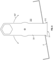
- Figure 8 shows a top view and Figure 7 shows a perspective view of embodiments of the tunnel which include a flared entrance (212, 312) which provides one form of the circular contour.
- the tunnel may pivot about the entrance to move the location of the exit aperture.
- the flare allows for the particular position of the tunnel exit to be moved around under the beehive frames while retaining a seal with the entrance wall 4.
- Figures 1-4 show another exemplary embodiment of the invention.
- the outer wall of the tunnel entrance region (11) comprises a circular contour (see more detail below).
- the tunnel may be pivoted through a wide range of angles until ultimately the tunnel sides interfere with the hive walls.
- the location of the exit aperture is swept about the base of the beehive such that the exit aperture can be located proximate the hive cluster.
- the circular form (52) maintains a seal to the outer wall of the beehive.
- Positioning of the tunnel exit proximate the location of the cluster provides the hive the best chance of suppressing a wasp invasion due to the typically large number of bees in proximity to the hive entrance which could assemble a defence.
- the tunnel exit forms a point of entry to the hive, and the point of entry is a location where bees will typically group in large quantities as the bee cluster.
- An invading wasp will typically wish to avoid engagement of a large cluster of bees and if it proceeds into the hive it will have a forced engagement with host bees by having to go via the cluster. This engagement leads to flight/flight pheromone release by the pest, e.g. wasp to a level that can no longer be reversed. The consequence is that the intruder becomes a marked target that induces an unavoidable natural reaction from the host bees into purposeful engagement with the pest.
- a wasp approaches a beehive by a typical path where the tunnel is installed.
- the wasp will enter the tunnel and, if the bees are active because the outside temperature is sufficiently high, will then encounter an extended length of tunnel that is occupied by many bees. Without the use of the tunnel what typically happens is that the depth of protected area ranges from 1 to 40mm only, as this is the width of the attached steel guard or the thickness of the hive box. It is easy for a wasp to assimilate to the hive when not threatened and the bees do not challenge the wasp.
- the wasp transgresses this barrier they are able to freely move around the interior of the hive in areas that are less populated by defending bees and having not emitted a flight/fight pheromone.
- the tunnel of the invention when the wasp enters the hive the protected area is considerably extended, the wasp feels threatened, releasing a flight/fight pheromone thus alerting the bees and allowing the bees to better dominate and defend against intruding wasps.
- a large cluster of bees is typically encountered at the exit aperture, irrespective of the outside temperature. This cluster functions to repel the wasp and the wasp may retreat from the tunnel or be engaged by defending bees. At this point the naturally induced behavioural reaction of the wasp pheromone can be at a maximum. At this point many and potentially all bees irrespective of their natural role in the hive may convert to guard bees and attack the predator.
- the tunnel has an interior defined by at least an upper tunnel surface portion and a lower tunnel surface portion which in some embodiments may be implemented by existing surfaces.
- the upper and lower tunnel surfaces are spaced apart by sidewalls which include contoured features to ensure a seal which prevents circumvention of the tunnel entranceway.
- the tunnel has an interior with a first opening located at one end and adapted to define a hive entranceway.
- the tunnel also has a second opening located in an upper tunnel surface portion to thereby define a tunnel exit and entrance to the beehive.
- the tunnel is a floor surface and a ceiling surface.
- the floor (which may be formed by the hive floor) and ceiling define a tunnel entrance there between at a first tunnel end. Located at an opposing end of the tunnel is another opening in the ceiling surface.
- the tunnel of the invention is 50mm or greater in length, preferably 100mm or greater, more preferably 150mm or greater, measured from the entrance to the first point at which bees can exit the tunnel. It can be up to 400mm or up to 300mm; it is often about 180-220mm as this length fits many hive sizes. In specific examples below the tunnel was approximately 200mm, this length being found to direct incoming bees or pests to directly below the cluster.
- the tunnel comprises a length of about: 50 to 200mm; 60 to 200mm; 70 to 200mm; 80 to 200mm; 90 to 200mm; 100 to 200mm; 110 to 200mm; 120 to 200mm; 130 to 200mm; 140 to 200mm; 150 to 200mm; 160 to 200mm; 160 to 200mm; 170 to 200mm; 180 to 200mm; 190 to 200mm; 50mm; 60mm; 70mm; 80mm; 90mm; 100mm; 110mm; 120mm; 130mm; 140mm; 150mm; 160mm; 170mm; 180mm; 190mm; or 200mm in length.
- the tunnel is approximately 200mm long, at which point bees can exit the tunnel vertically upwards.
- Tunnel length and/or position is preferably such that invaders can not avoid arriving at the cluster (during winter, also referred to as the winter cluster).
- a user adjusts tunnel location with respect to other hive elements to position the tunnel exit closer towards the actual or anticipated cluster position for the hive.
- the cluster will be backed up against the insulation wall made of honey by the bees relative to the coldest side of the hive and least exposure of the sun. The bees will usually not be too far forward to be out in the cold away from the insulation wall.
- the tunnel length can also be adjustable to adapt to the design of the hive, different cluster positions depending on the geographic location of the hive, available sunlight hours that falls on the hive and the time of day this falls as well as breed characteristics.
- Telescopic tunnels with wall slide that side relative to each other, can be used to provide adjustable tunnel length.
- the tunnel entrance is 30mm or greater in width, more suitably 40mm or greater, preferably 50mm or greater.
- the entrance is up to 200mm in width, more suitably up to 150mm, preferably up to 100mm.
- the tunnel comprises an entrance width of about: 50 to 150mm; 60 to 150mm; 70 to 150mm; 80 to 150mm; 90 to 150mm; 100 to 150mm; 110 to 150mm; 120 to 150mm; 130 to 150mm; 140 to 150mm; 50mm; 60mm; 70mm; 80mm; 90mm; 100mm; 110mm; 120mm; 130mm; 140mm; or 150mm opening width.
- the entrance is approximately 60 - 65mm wide.
- the tunnel height is suitably 12mm or less, preferably 11mm or less and more preferably 10mm or less; a height of e.g. 10mm indicates the tunnel can accommodate a bee of that height, etc.
- the tunnel comprises an interior height of about 8 to 10mm.
- the interior height is uniform.
- the interior height changes and has a minimum height of about 8-10mm.
- the height is at least 6mm, preferably at least 7mm.
- the tunnel when installed e.g. as a preventative measure as opposed to during a full attack, the tunnel is suitably fixed in place so as to prevent movement away from under the cluster.
- Provision of the rough surface can make it much easier for the bees to enter and exit the hive through the tunnel and/or periscope. It can also make removing debris from the hive by the bees easier.
- the steel molds of the tunnel parts and the periscope were sandblasted. Once the apparatus are injection molded and come out of the mold, the inside surfaces of the parts have a corresponding slightly rough surface; like very light sand paper to the touch. The outside surfaces of the apparatus do not need to be made this way and are generally smooth.
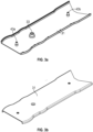
- Figs. 1a, 1b , 2a, 2b , 3a and 3b depict a first embodiment of the invention (10) having an upper tunnel portion (31) and a lower tunnel portion (32).
- the tunnel has an entrance (11) and an exit (14).
- the entrance (11) is positioned external to the beehive and the exit (14) internal to the hive.
- the exit (14) is in the upper surface of the apparatus to force pests attempting to enter the hive upwards into the cluster.
- the outer wall of the tunnel entrance (11) comprises a circular contour as a frusto-circular plan form (52) which is outwardly convex and arranged on opposing sidewalls.
- the tunnel further has drainage holes (54).
- the upper tunnel portion (31) and lower tunnel portion (32) are secured together by engaging a boss (33) in the upper tunnel portion (31) and a complementary aperture (34) in the lower tunnel portion (32). Once the boss (33) and aperture (34) are engaged, a nail or screw may be passed through the channel (40) formed by the engaged boss (33) and aperture (34) to fix the apparatus to the base of a beehive.
- This embodiment also has two further structure points comprising a structure boss (43a, b) in the upper tunnel portion (31) and a structure aperture (44a, b) in the lower tunnel portion (32). When the upper tunnel portion (31) and lower tunnel portion (32) are fitted together, the structure bosses (43) and structure apertures (44) are engaged to prevent the collapse of the tunnel.
- the tunnel is about 200mm long from the front entrance to the first point at which bees can exit the tunnel, with an overall length of about 270mm.
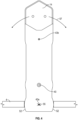
- Fig. 4 further depicts the first embodiment of the invention fitted on the bottom board of a beehive and passing through the hive wall (4).
- the frusto-circular section (52) of the apparatus allows the apparatus to be pivoted around a point X (55, centred in this case approximately on structure point 43a) according to the arrows (57) shown in fig. 4 prior to being fixed in place.
- Figs. 5 , 6a and 6b show a second embodiment of the invention (110) having a tunnel and comprising an upper tunnel portion (131) and a lower tunnel portion (132).
- the tunnel has an entrance (111) and an exit (114).
- the upper tunnel portion (131) and lower tunnel portion (132) have a flare (112) at the entrance (111), this allows the apparatus to be pivoted whilst maintaining a seal between the apparatus and the entrance to the beehive.
- the upper tunnel portion (131) and lower tunnel portion (132) are secured together by engaging a boss (133) in the upper tunnel portion (131) and a complementary aperture (134) in the lower tunnel portion (132).
- a nail or screw may be passed through the channel (140) formed by the engaged boss (133) and aperture (134) to fix the apparatus to the base of a beehive.
- This embodiment also depicts additional structure points comprising a structure boss (143a, b) in the upper tunnel portion (131) and a structure aperture (144a, b) in the lower tunnel portion (132). When the upper tunnel portion (131) and lower tunnel portion (132) are fitted together, the structure bosses (143) and structure apertures (144) are engaged to prevent the collapse of the tunnel.
- Fig. 7 depicts a third embodiment of the invention (210) having a tunnel, upper tunnel portion (231) and lower tunnel portion (232).
- the centre of the tunnel comprises a circular contour as a frusto-circular plan form (256) about the channel (240).
- the channel (240) blocks the centre of the tunnel, therefore the frusto-circular section (256) allows additional space for bees to pass around the channel (240) within the tunnel.
- Fig. 7 further shows how the apparatus can be rotated according to the arrows (257), whilst maintaining a seal between the flare (212) at the entrance (211) to the tunnel and the entrance to the beehive.
- Fig. 8 depicts a fourth embodiment of the invention (310) having a tunnel and an upper tunnel portion (331), in this embodiment there is no lower tunnel protection as the lower surface of the tunnel is formed by the flat base / bottom board of the beehive.
- Fig. 8 shows how the apparatus can be rotated according to the arrows (357), whilst maintaining a seal between the flare (312) at the entrance (311) to the tunnel through the wall (4) of a beehive.
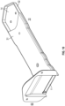
- Figs. 9a, 9b and 10 show an optional periscope addition to be used with the apparatus of the invention - shown connected to the first embodiment in fig. 10 .
- Screws or nails can be passed through the holes (62) to secure the periscope (60) over an irregular shaped beehive entrance (not shown).
- the periscope (60) attaches to an inner face of the hive and has an entrance covering portion (64) and an opening (65).
- the apparatus of the invention (10) may be connected to the opening (65) to form a seal between the opening (65) and the entrance (11, 111, 211, 311) of the apparatus of the invention; this allows the apparatus to be used on non-standard beehive entrances, for example circular entrances which may be positioned higher than the base of the hive. As described above access to the hive is then via the entrance (11, 111, 211, 311) of the apparatus of the invention.
- the bees will naturally defend only a hive entrance when the outside temperature is sufficiently warm.
- the entrance may be 10 to 370mm wide by about 10mm high. The depth varies from 1 to 40mm and essentially just the depth of the thickness of the box or applied entrance reducer. So, once the wasp passes this entrance and the few guard bees that are there, they are into the hive and are strong enough to dominate and do whatever they please.
- the tunnel according to the above described embodiments forces a wasp to enter the hive and then have to walk the length of the tunnel, this being e.g. about 200mm in length. Along the way the wasp will typically face a barrage of defending bees and is often completely outnumbered.
- the wasp once inside the hive may not then identify the location in which to exit the hive. Any wasp that is already inside the hive and is wanting to exit does not have a clear access to the internal exit aperture, which for a wasp trying to exit is now in reverse the entry point of the tunnel, because of the larger cluster of bees at this position.
- the wasps perpetually try to exit the hive by searching for gaps around the internal perimeter of the hive; however, there are no exit points for them on the hive perimeter so at some point in time they die either due to sustained bee attack or from running out of resources and effectively starve or dehydrate.
- Wasp lures were positioned on and around the test site two weeks prior to testing for the purpose of luring wasps to the test site and substantially increasing the number of wasps at the test site, and making sure a sufficiently high number of wasps would be present to enter the test hives once testing was started.
- Wasps were chosen as the predator in this experiment since it is easier to film a wasp attack than it is to film robbing of bees by bees. They are also prevalent in New Zealand.
- a console was set up with the same dimensions as the commonly used, commercial 10-frame Langsroth ® beehive box - 610mm high ⁇ 410mm wide ⁇ 510mm long.
- the top surface of the console was made of glass and a camera was placed inside the console on the ground, facing upwards. The inside of the console was blacked out to keep any disrupting light out.
- Dav 8 4 hives were brought to the test site. Each beehive was placed on top of a console, the beehive itself had no floor and the glass top surface of the console acted as the beehive floor. This allowed the camera in the console to film the activity inside the beehive. At this time, the wasp lures were removed.
- Hives were set up next to each other all facing same direction with equal spacing apart. Hives were then manually weakened by removing frames with bees and stores. Frames were replaced with empty frames. All four hives were left with 1.5-2 full frames of bees and stores. All queens were of a similar age and quality in an effort to eliminate any manageable variances within the test colonies to provide a comparable base line.
- the hives were left alone for three days with a 65 ⁇ 10mm galvanised mouse guard on the entrance protecting them. Filming commenced and there were general visual observations made.
- Dav 12 Manual observation of the entrance of the hive was made and only clearly identified sitings were recorded in the count. With this count, 1 represents an entry and exit. Any wasp that went out of sight inside the entrance was classified as a successful entry.
- the apparatus of the invention was installed in two hives by inserting it through the front entrance from the outside leaving no gaps or other entrances for bees or wasps to enter the beehive other than via the tunnel. Only the top half of the apparatus was used in this testing so as to be able to see and record movements in the tunnel during the testing. The exit to the tunnel was installed facing upwards close to the cluster within the beehive, though not fixed in place. This was to assess if the apparatus could be used as a way of stopping an attack in progress. If no action was taken, a hive would be threatened and destroyed or a bee-keeper would need to relocate the hive to at least 3 km away from its current location so that the wasps could not continue the attack.
- the apparatus was inserted into the single entrance to the hive meaning, once it was in place, all bees and wasps had to enter and exit the hive through the apparatus.
- the agitated wasps were observed to then vacate the hive and move to the unprotected adjacent hive, leave the area altogether or grab a bee as an alternative source of protein and bite it in half, taking half back to their colony as a consolation prize. This would be their second choice protein source for this time of the year.
- the monitoring equipment was kept in place for an extended period after the test, to confirm that with the apparatus installed there were no tunnel blockages and all hive debris was removed as in unmodified hives.
- both hives we replaced the bottom base with a glass floor. Both hives were observed from below with cameras.
- the apparatus used was a version that is a single piece, without a floor (not needed as the glass surface is flat and the top tunnel portion sits flat on and tight to the flat surface which forms the tunnel floor) so we could observe from below what was happening inside the tunnel as well.
- Both hives had a wooden landing board outside the front of their entrances.
- the hive with the tunnel of the invention showed extracted humidity forming beads of water on the landing board in front of the hive entry/exit.
- the hive without the tunnel showed a damp spot on the landing board in front of the hive entry/exit, but not nearly as much humidity as the hive with the apparatus.
Landscapes
- Life Sciences & Earth Sciences (AREA)
- Environmental Sciences (AREA)
- Animal Husbandry (AREA)
- Biodiversity & Conservation Biology (AREA)
- Catching Or Destruction (AREA)
Claims (15)
- Bienenstockeingangstunnel (10), umfassend:einen länglichen rohrförmigen Tunnel, der zur Anbringung an der Basis eines Bienenstocks ausgelegt ist, wobei der Tunnel (10) einen Innenraum umfasst, der durch mindestens einen oberen Tunneloberflächenabschnitt (31) definiert ist, wobei der Tunnel (10) eine erste Öffnung umfasst, die an einem Ende angeordnet ist, um dadurch einen Bienenstockeingang (11) zu definieren;wobei der Tunnel (10) eine Höhe aufweist, die nicht mehr vertikalen Raum bereitstellt, als eine Biene erfordert; undwobei der Tunnel (10) ferner eine zweite Öffnung umfasst, die in dem oberen Tunneloberflächenabschnitt (31) angeordnet ist, um dadurch einen Tunnelausgang (14) zu definieren.
- Bienenstockeingangstunnel (10) nach Anspruch 1 für einen Bienenstock, der eine Außenwand mit einem Bienenstockeingangsdurchlass aufweist, wobei der Tunnel (10) Folgendes umfasst:eine längliche Struktur, die einen Eingangsdurchlass an einem ersten Ende und einen Ausgangsdurchlass, der an oder nahe einem gegenüberliegenden Ende angeordnet ist, aufweist, undwobei der Tunnel (10) ferner gegenüberliegende Seitenwände umfasst, wobei jede gegenüberliegende Seitenwand eine nach außen gerichtete Kontur umfasst, die nahe dem Eingangsdurchlass angeordnet ist, wobei die Kontur dazu betreibbar ist, eine Abdichtung mit der Außenwand (4) des Bienenstocks zu bilden und Schwenken des Ausgangsdurchlasses innerhalb des Bienenstocks zu erleichtern, während diese Abdichtung aufrechterhalten wird.
- Bienenstockeingangstunnel (10) nach einem der Ansprüche 1 bis 2, wobei der Tunnel (10) eine Deckenoberfläche umfasst und wobei der Tunnelausgang (14) oder der Ausgangsdurchlass in der Deckenoberfläche angeordnet ist.
- Bienenstockeingangstunnel (10) nach einem vorhergehenden Anspruch, wobei der Tunnel (10) einen Weg bereitstellt, der sich zwischen der Außenseite des Bienenstocks und einem Ort in der Nähe der aktiven Ansammlung innerhalb des Stocks erstreckt.
- Bienenstockeingangstunnel (10) nach einem vorhergehenden Anspruch, wobei der Tunnel (10) eine abdichtende Oberfläche umfasst, die für Eingriff mit der Außenwand des Stocks geformt ist und so geformt ist, dass sie eine Bewegung des Tunnels (10) zulässt, um den Tunnelausgang (14) wünschenswert zu positionieren, während die Abdichtung mit der Außenwand (4) des Stocks beibehalten wird.
- Bienenstockeingangstunnel (10) nach einem vorhergehenden Anspruch, wobei der Tunnel (10) eine Innenraumhöhe von etwa 8 bis 10 mm umfasst.
- Bienenstockeingangstunnel (10) nach einem vorhergehenden Anspruch, umfassend eine Eingangsbreite von etwa 50 bis 150 mm.
- Bienenstockeingangstunnel (10) nach einem vorhergehenden Anspruch, wobei der Tunnel (10) eine Länge von etwa 50 bis 200 mm umfasst.
- Bienenstockeingangstunnel (10) nach einem vorhergehenden Anspruch, der aus zwei Teilen aufgebaut ist, bei denen es sich um einen unteren Abschnitt (32) des Tunnels (10) einschließlich des Tunnelbodens und einen oberen Abschnitt (31) des Tunnels (10) einschließlich der Tunneldecke handelt.
- Bienenstockeingangstunnel (10) nach einem der Ansprüche 1 bis 8, wobei der Tunnel (10) durch einen oberen Tunnelbereich (31) gebildet ist, der so ausgelegt ist, dass er mit einem bereits bestehenden Boden eines Bienenstocks betreibbar in Eingriff tritt.
- Bienenstockeingangstunnel (10) nach einem vorhergehenden Anspruch, wobei der Tunneleingang (11) mindestens in den Außenwänden eine kreisförmige Kontur umfasst, die zulässt, dass die Position des Tunnelausgangsdurchlasses geschwenkt wird, während eine Abdichtung mit der Stockwand (4) beibehalten wird.
- Bienenstockeingangstunnel (10) nach Anspruch 11, wobei der Tunnel (10) einen aufgeweiteten Eingang umfasst.
- Verfahren zum Installieren eines Bienenstockeingangstunnels (10) in einem Bienenstock, wobei das Verfahren die folgenden Schritte umfasst:Bereitstellen des Bienenstockeingangstunnels (10) nach einem vorherigen Anspruch,Einsetzen des Tunnels (10) in einen Spalt in der Außenwand (4) eines Bienenstocks, sodass eine Abdichtung zwischen der Region des Tunnels (10) nahe dem Tunneleingang (11) und der Außenwand (4) des Bienenstocks erzeugt wird, undSchwenken des Tunnelausgangsdurchlasses, um dadurch den Ausgang (14) nahe einer Ansammlung des Stocks anzuordnen.
- Verfahren nach Anspruch 13, wobei der Tunnel (10) eine Innenraumhöhe von bis zu 10 mm, eine Eingangsbreite von mindestens 50 mm und eine Länge von mindestens 50 mm umfasst.
- Verfahren nach Anspruch 13, wobei der Tunnel (10) eine Innenraumhöhe von 8 bis 10 mm, eine Eingangsbreite von 50 bis 150 mm und eine Länge von 50 bis 200 mm umfasst.
Applications Claiming Priority (2)
| Application Number | Priority Date | Filing Date | Title |
|---|---|---|---|
| NZ74955218 | 2018-12-21 | ||
| PCT/EP2019/086673 WO2020127966A1 (en) | 2018-12-21 | 2019-12-20 | Anti-predator device for bee hive |
Publications (3)
| Publication Number | Publication Date |
|---|---|
| EP3897113A1 EP3897113A1 (de) | 2021-10-27 |
| EP3897113C0 EP3897113C0 (de) | 2024-05-22 |
| EP3897113B1 true EP3897113B1 (de) | 2024-05-22 |
Family
ID=69137887
Family Applications (1)
| Application Number | Title | Priority Date | Filing Date |
|---|---|---|---|
| EP19832384.2A Active EP3897113B1 (de) | 2018-12-21 | 2019-12-20 | Räuberschutzvorrichtung für bienenstöcke |
Country Status (6)
| Country | Link |
|---|---|
| US (1) | US12250928B2 (de) |
| EP (1) | EP3897113B1 (de) |
| CN (1) | CN113226019B (de) |
| AU (1) | AU2019410691A1 (de) |
| CA (1) | CA3122717A1 (de) |
| WO (1) | WO2020127966A1 (de) |
Family Cites Families (17)
| Publication number | Priority date | Publication date | Assignee | Title |
|---|---|---|---|---|
| GB619449A (en) * | 1946-12-11 | 1949-03-09 | Peter William Stanley | Improvements in or relating to bee hives |
| JP4703913B2 (ja) * | 2001-07-10 | 2011-06-15 | 昭彦 大槻 | 養蜂巣箱のスズメバチ撃退用電気ゲート |
| KR200270493Y1 (ko) * | 2002-01-14 | 2002-04-03 | 김향숙 | 벌통 |
| CA2763505C (en) * | 2009-05-29 | 2018-09-18 | Biobest Belgium Nv | Hive-mounted disseminator device |
| KR101068412B1 (ko) * | 2009-09-03 | 2011-09-29 | 김주홍 | 꿀벌보호장치 |
| CN101999314B (zh) * | 2010-10-09 | 2012-10-31 | 中国农业科学院蜜蜂研究所 | 一种蜜蜂授粉强度控制专用箱 |
| EP2478764B1 (de) * | 2011-01-21 | 2014-05-21 | King Saud University | Langstroth-Modifizierung |
| KR200475464Y1 (ko) * | 2013-03-19 | 2014-12-03 | 김장춘 | 벌통용 환기장치 |
| CN203985536U (zh) * | 2014-07-24 | 2014-12-10 | 天津市澍丰农业科技有限公司 | 一种方便转移的蜂箱 |
| KR200478892Y1 (ko) * | 2014-08-08 | 2015-11-26 | 이천호 | 벌통용 꿀벌보호장치 |
| ES2588206B1 (es) * | 2015-03-29 | 2017-08-03 | Arturo CARRILLO SÁNCHEZ | Elemento para las pestañas de los cuadros, cuadro con pestañas adaptadas, pestaña para cuadros, base de apoyo antiadherente y procedimientos. |
| KR101829584B1 (ko) * | 2017-06-19 | 2018-02-19 | 김호겸 | 말벌 차단 장치 |
| KR102019200B1 (ko) * | 2017-10-23 | 2019-09-06 | 송인택 | 탈부착식 말벌 방어기 및 양봉 벌통 |
| KR101922670B1 (ko) * | 2017-11-17 | 2018-11-27 | 전응식 | 양봉통의 말벌 방어터널 |
| CN207612930U (zh) * | 2017-12-06 | 2018-07-17 | 界首市胜昌塑业有限公司 | 一种环保塑料蜂箱混料装置 |
| US11547096B2 (en) * | 2019-08-29 | 2023-01-10 | Richard Holmes | Insertable beehive entrance device |
| US11304409B2 (en) * | 2020-06-26 | 2022-04-19 | Martin Hanscom | Murder hornet excluder |
-
2019
- 2019-12-20 EP EP19832384.2A patent/EP3897113B1/de active Active
- 2019-12-20 CA CA3122717A patent/CA3122717A1/en active Pending
- 2019-12-20 US US17/416,777 patent/US12250928B2/en active Active
- 2019-12-20 CN CN201980085226.7A patent/CN113226019B/zh active Active
- 2019-12-20 WO PCT/EP2019/086673 patent/WO2020127966A1/en not_active Ceased
- 2019-12-20 AU AU2019410691A patent/AU2019410691A1/en not_active Abandoned
Also Published As
| Publication number | Publication date |
|---|---|
| CN113226019A (zh) | 2021-08-06 |
| CA3122717A1 (en) | 2020-06-25 |
| WO2020127966A1 (en) | 2020-06-25 |
| AU2019410691A1 (en) | 2021-06-10 |
| EP3897113C0 (de) | 2024-05-22 |
| EP3897113A1 (de) | 2021-10-27 |
| CN113226019B (zh) | 2023-03-21 |
| US20220071178A1 (en) | 2022-03-10 |
| US12250928B2 (en) | 2025-03-18 |
Similar Documents
| Publication | Publication Date | Title |
|---|---|---|
| EP3250028A2 (de) | Vorrichtung zur verwaltung des ausschwärmens von honigbienen | |
| GB2586263A (en) | Beehive entrance apparatus | |
| US7632167B1 (en) | Selective insect trapping system | |
| KR102019200B1 (ko) | 탈부착식 말벌 방어기 및 양봉 벌통 | |
| US20240008458A1 (en) | System, method, and apparatus for active pest denial, apiary monitoring and management | |
| KR101436571B1 (ko) | 해충의 애벌레 출입방지구조를 갖는 벌통 | |
| EP3897113B1 (de) | Räuberschutzvorrichtung für bienenstöcke | |
| KR20180005771A (ko) | 토종벌통의 토종벌 출입문 | |
| US11304409B2 (en) | Murder hornet excluder | |
| US11540494B2 (en) | Beehive excluder including stacked rows of openings and cantilevered extension clips | |
| JP3760320B2 (ja) | ミツバチ保護用スズメバチ遮断装置 | |
| JP3203946U (ja) | 防除器 | |
| KR100552350B1 (ko) | 꿀벌소상 해충출입 방지장치 | |
| US20210100223A1 (en) | Holmes Trap in | |
| KR200343501Y1 (ko) | 꿀벌소상 해충출입 방지장치 | |
| KR102877830B1 (ko) | 도봉 차단 구조체 및 이를 구비하는 양봉 장치 | |
| KR102721728B1 (ko) | 유해조류 포획트랩용 게이트유닛과 이를 이용한 유해조류 포획트랩 | |
| KR20210053778A (ko) | 꿀벌의 벌통에 설치되는 말벌 포획기 | |
| JP7085575B2 (ja) | 分蜂捕獲器。分蜂群を捕獲し新巣箱へ移動する分蜂捕獲器。 | |
| KR20180014303A (ko) | 벌통용 해충 침입방지 구조물 및 이를 포함하는 벌통 | |
| CN113207814A (zh) | 一种利用分蜂热扩繁蜂群的防飞逃装置及方法 | |
| US8651060B2 (en) | Birdhouse | |
| CN120266781A (zh) | 一种蜜蜂弱群保护器及使用方法 | |
| TWI826598B (zh) | 入侵防止裝置 | |
| TR2024003427A2 (tr) | Ari kovanlarini soyulmaya ve kötü hava koşullarina karşi korumayi amaçlayan çok amaçli bi̇ryönlendi̇rme ve bağlanti aparati |
Legal Events
| Date | Code | Title | Description |
|---|---|---|---|
| STAA | Information on the status of an ep patent application or granted ep patent |
Free format text: STATUS: UNKNOWN |
|
| STAA | Information on the status of an ep patent application or granted ep patent |
Free format text: STATUS: THE INTERNATIONAL PUBLICATION HAS BEEN MADE |
|
| PUAI | Public reference made under article 153(3) epc to a published international application that has entered the european phase |
Free format text: ORIGINAL CODE: 0009012 |
|
| STAA | Information on the status of an ep patent application or granted ep patent |
Free format text: STATUS: REQUEST FOR EXAMINATION WAS MADE |
|
| 17P | Request for examination filed |
Effective date: 20210708 |
|
| AK | Designated contracting states |
Kind code of ref document: A1 Designated state(s): AL AT BE BG CH CY CZ DE DK EE ES FI FR GB GR HR HU IE IS IT LI LT LU LV MC MK MT NL NO PL PT RO RS SE SI SK SM TR |
|
| DAV | Request for validation of the european patent (deleted) | ||
| DAX | Request for extension of the european patent (deleted) | ||
| GRAP | Despatch of communication of intention to grant a patent |
Free format text: ORIGINAL CODE: EPIDOSNIGR1 |
|
| STAA | Information on the status of an ep patent application or granted ep patent |
Free format text: STATUS: GRANT OF PATENT IS INTENDED |
|
| INTG | Intention to grant announced |
Effective date: 20240103 |
|
| GRAS | Grant fee paid |
Free format text: ORIGINAL CODE: EPIDOSNIGR3 |
|
| GRAA | (expected) grant |
Free format text: ORIGINAL CODE: 0009210 |
|
| STAA | Information on the status of an ep patent application or granted ep patent |
Free format text: STATUS: THE PATENT HAS BEEN GRANTED |
|
| AK | Designated contracting states |
Kind code of ref document: B1 Designated state(s): AL AT BE BG CH CY CZ DE DK EE ES FI FR GB GR HR HU IE IS IT LI LT LU LV MC MK MT NL NO PL PT RO RS SE SI SK SM TR |
|
| REG | Reference to a national code |
Ref country code: GB Ref legal event code: FG4D |
|
| REG | Reference to a national code |
Ref country code: CH Ref legal event code: EP |
|
| REG | Reference to a national code |
Ref country code: DE Ref legal event code: R096 Ref document number: 602019052694 Country of ref document: DE |
|
| REG | Reference to a national code |
Ref country code: IE Ref legal event code: FG4D |
|
| U01 | Request for unitary effect filed |
Effective date: 20240531 |
|
| U07 | Unitary effect registered |
Designated state(s): AT BE BG DE DK EE FI FR IT LT LU LV MT NL PT SE SI Effective date: 20240610 |
|
| PG25 | Lapsed in a contracting state [announced via postgrant information from national office to epo] |
Ref country code: IS Free format text: LAPSE BECAUSE OF FAILURE TO SUBMIT A TRANSLATION OF THE DESCRIPTION OR TO PAY THE FEE WITHIN THE PRESCRIBED TIME-LIMIT Effective date: 20240922 |
|
| PG25 | Lapsed in a contracting state [announced via postgrant information from national office to epo] |
Ref country code: HR Free format text: LAPSE BECAUSE OF FAILURE TO SUBMIT A TRANSLATION OF THE DESCRIPTION OR TO PAY THE FEE WITHIN THE PRESCRIBED TIME-LIMIT Effective date: 20240522 |
|
| PG25 | Lapsed in a contracting state [announced via postgrant information from national office to epo] |
Ref country code: GR Free format text: LAPSE BECAUSE OF FAILURE TO SUBMIT A TRANSLATION OF THE DESCRIPTION OR TO PAY THE FEE WITHIN THE PRESCRIBED TIME-LIMIT Effective date: 20240823 |
|
| PG25 | Lapsed in a contracting state [announced via postgrant information from national office to epo] |
Ref country code: ES Free format text: LAPSE BECAUSE OF FAILURE TO SUBMIT A TRANSLATION OF THE DESCRIPTION OR TO PAY THE FEE WITHIN THE PRESCRIBED TIME-LIMIT Effective date: 20240522 |
|
| PG25 | Lapsed in a contracting state [announced via postgrant information from national office to epo] |
Ref country code: PL Free format text: LAPSE BECAUSE OF FAILURE TO SUBMIT A TRANSLATION OF THE DESCRIPTION OR TO PAY THE FEE WITHIN THE PRESCRIBED TIME-LIMIT Effective date: 20240522 |
|
| PG25 | Lapsed in a contracting state [announced via postgrant information from national office to epo] |
Ref country code: PL Free format text: LAPSE BECAUSE OF FAILURE TO SUBMIT A TRANSLATION OF THE DESCRIPTION OR TO PAY THE FEE WITHIN THE PRESCRIBED TIME-LIMIT Effective date: 20240522 Ref country code: NO Free format text: LAPSE BECAUSE OF FAILURE TO SUBMIT A TRANSLATION OF THE DESCRIPTION OR TO PAY THE FEE WITHIN THE PRESCRIBED TIME-LIMIT Effective date: 20240822 Ref country code: IS Free format text: LAPSE BECAUSE OF FAILURE TO SUBMIT A TRANSLATION OF THE DESCRIPTION OR TO PAY THE FEE WITHIN THE PRESCRIBED TIME-LIMIT Effective date: 20240922 Ref country code: HR Free format text: LAPSE BECAUSE OF FAILURE TO SUBMIT A TRANSLATION OF THE DESCRIPTION OR TO PAY THE FEE WITHIN THE PRESCRIBED TIME-LIMIT Effective date: 20240522 Ref country code: GR Free format text: LAPSE BECAUSE OF FAILURE TO SUBMIT A TRANSLATION OF THE DESCRIPTION OR TO PAY THE FEE WITHIN THE PRESCRIBED TIME-LIMIT Effective date: 20240823 Ref country code: ES Free format text: LAPSE BECAUSE OF FAILURE TO SUBMIT A TRANSLATION OF THE DESCRIPTION OR TO PAY THE FEE WITHIN THE PRESCRIBED TIME-LIMIT Effective date: 20240522 Ref country code: RS Free format text: LAPSE BECAUSE OF FAILURE TO SUBMIT A TRANSLATION OF THE DESCRIPTION OR TO PAY THE FEE WITHIN THE PRESCRIBED TIME-LIMIT Effective date: 20240822 |
|
| U1N | Appointed representative for the unitary patent procedure changed after the registration of the unitary effect |
Representative=s name: SCHLICH; GB |
|
| U20 | Renewal fee for the european patent with unitary effect paid |
Year of fee payment: 6 Effective date: 20241213 |
|
| PG25 | Lapsed in a contracting state [announced via postgrant information from national office to epo] |
Ref country code: CZ Free format text: LAPSE BECAUSE OF FAILURE TO SUBMIT A TRANSLATION OF THE DESCRIPTION OR TO PAY THE FEE WITHIN THE PRESCRIBED TIME-LIMIT Effective date: 20240522 |
|
| PG25 | Lapsed in a contracting state [announced via postgrant information from national office to epo] |
Ref country code: SK Free format text: LAPSE BECAUSE OF FAILURE TO SUBMIT A TRANSLATION OF THE DESCRIPTION OR TO PAY THE FEE WITHIN THE PRESCRIBED TIME-LIMIT Effective date: 20240522 Ref country code: RO Free format text: LAPSE BECAUSE OF FAILURE TO SUBMIT A TRANSLATION OF THE DESCRIPTION OR TO PAY THE FEE WITHIN THE PRESCRIBED TIME-LIMIT Effective date: 20240522 |
|
| PG25 | Lapsed in a contracting state [announced via postgrant information from national office to epo] |
Ref country code: SM Free format text: LAPSE BECAUSE OF FAILURE TO SUBMIT A TRANSLATION OF THE DESCRIPTION OR TO PAY THE FEE WITHIN THE PRESCRIBED TIME-LIMIT Effective date: 20240522 |
|
| PG25 | Lapsed in a contracting state [announced via postgrant information from national office to epo] |
Ref country code: SM Free format text: LAPSE BECAUSE OF FAILURE TO SUBMIT A TRANSLATION OF THE DESCRIPTION OR TO PAY THE FEE WITHIN THE PRESCRIBED TIME-LIMIT Effective date: 20240522 Ref country code: SK Free format text: LAPSE BECAUSE OF FAILURE TO SUBMIT A TRANSLATION OF THE DESCRIPTION OR TO PAY THE FEE WITHIN THE PRESCRIBED TIME-LIMIT Effective date: 20240522 Ref country code: RO Free format text: LAPSE BECAUSE OF FAILURE TO SUBMIT A TRANSLATION OF THE DESCRIPTION OR TO PAY THE FEE WITHIN THE PRESCRIBED TIME-LIMIT Effective date: 20240522 Ref country code: CZ Free format text: LAPSE BECAUSE OF FAILURE TO SUBMIT A TRANSLATION OF THE DESCRIPTION OR TO PAY THE FEE WITHIN THE PRESCRIBED TIME-LIMIT Effective date: 20240522 |
|
| REG | Reference to a national code |
Ref country code: DE Ref legal event code: R097 Ref document number: 602019052694 Country of ref document: DE |
|
| PLBE | No opposition filed within time limit |
Free format text: ORIGINAL CODE: 0009261 |
|
| STAA | Information on the status of an ep patent application or granted ep patent |
Free format text: STATUS: NO OPPOSITION FILED WITHIN TIME LIMIT |
|
| 26N | No opposition filed |
Effective date: 20250225 |
|
| PG25 | Lapsed in a contracting state [announced via postgrant information from national office to epo] |
Ref country code: MC Free format text: LAPSE BECAUSE OF FAILURE TO SUBMIT A TRANSLATION OF THE DESCRIPTION OR TO PAY THE FEE WITHIN THE PRESCRIBED TIME-LIMIT Effective date: 20240522 |
|
| REG | Reference to a national code |
Ref country code: CH Ref legal event code: PL |
|
| PG25 | Lapsed in a contracting state [announced via postgrant information from national office to epo] |
Ref country code: CH Free format text: LAPSE BECAUSE OF NON-PAYMENT OF DUE FEES Effective date: 20241231 |
|
| PG25 | Lapsed in a contracting state [announced via postgrant information from national office to epo] |
Ref country code: IE Free format text: LAPSE BECAUSE OF NON-PAYMENT OF DUE FEES Effective date: 20241220 |
|
| PGFP | Annual fee paid to national office [announced via postgrant information from national office to epo] |
Ref country code: GB Payment date: 20251211 Year of fee payment: 7 |
|
| U20 | Renewal fee for the european patent with unitary effect paid |
Year of fee payment: 7 Effective date: 20251211 |