EP3896383A1 - Optisches system mit reflektivem innerem rotpunktvisier mit verbesserter monochromatizität und verdeckung, optisches system mit zwei lichtern und drei farben und visier dafür - Google Patents
Optisches system mit reflektivem innerem rotpunktvisier mit verbesserter monochromatizität und verdeckung, optisches system mit zwei lichtern und drei farben und visier dafür Download PDFInfo
- Publication number
- EP3896383A1 EP3896383A1 EP19908320.5A EP19908320A EP3896383A1 EP 3896383 A1 EP3896383 A1 EP 3896383A1 EP 19908320 A EP19908320 A EP 19908320A EP 3896383 A1 EP3896383 A1 EP 3896383A1
- Authority
- EP
- European Patent Office
- Prior art keywords
- light
- lens
- chip module
- emitted
- filter
- Prior art date
- Legal status (The legal status is an assumption and is not a legal conclusion. Google has not performed a legal analysis and makes no representation as to the accuracy of the status listed.)
- Granted
Links
Images


Classifications
-
- F—MECHANICAL ENGINEERING; LIGHTING; HEATING; WEAPONS; BLASTING
- F41—WEAPONS
- F41G—WEAPON SIGHTS; AIMING
- F41G1/00—Sighting devices
- F41G1/06—Rearsights
- F41G1/14—Rearsights with lens
-
- F—MECHANICAL ENGINEERING; LIGHTING; HEATING; WEAPONS; BLASTING
- F41—WEAPONS
- F41G—WEAPON SIGHTS; AIMING
- F41G1/00—Sighting devices
- F41G1/30—Reflecting-sights specially adapted for smallarms or ordnance
Definitions
- the present disclosure relates to a reflective inner red dot sight optical system with improved monochromaticity and concealment, two-light three-color optical system, and a sight thereof.
- the light emitted by the LED chip installed on the existing gun sight is reflected by the cemented lens to form an aiming spot
- the light-emitting wave band of the LED chip is 560 ⁇ 80nm or other wavebands
- the light emitted from the LED often contains red, yellow, green and other colors
- this multi-color light is reflected by the narrow-band interference filter film and the long-wavelength cutoff filter film plated on the cemented lens
- the light with a wavelength of 545 ⁇ 15nm and greater than 600nm is reflected into the human eye
- there will be multiple target images with overlapping colors (multi-wavelength light projecting target images of different colors) which affects the clarity of the target, causes aiming errors, and reduces shooting accuracy.
- the band energy emitted by the LED chip is very strong, which is easy to be detected by human, exposes the target, and reduces the concealment of the sight.
- the existing inner red dot sights have single light, two-light or three-light (multiple-light), however, the realization of the three-color function requires a corresponding number of LED chips or light-emitting units or light-emitting modules, which results in high power consumption, unswitchable graphics, complex installation structure, high debugging and maintenance costs, and the size of the sight will also increase. As a result, the carrying weight and volume have increased to varying degrees, making it inportability.
- the first purpose of the present disclosure is to overcome the problem that there are two or more colors of target images reflected by the lens or lens group or cemented lens into the human eye because the existing sighting device has a wide light-emitting band of the LED chip, and the problem that the light emitted from the lens or the lens group or the cemented lens is too strong, leading to reduced concealment.
- the second purpose is to overcome the problems of complex structure, large weight and volume of the existing multi-beam sights and the cost is high and inportability.
- the present disclosure provides a reflective inner red dot sight optical system with improved monochromaticity and concealment
- the optical system includes an LED chip and a lens for reflecting light emitted from the LED chip, a filter plated with a narrow-band interference filter film is provided near the LED chip and located between the LED chip and the lens;
- the filter (2) is used to filter out light of a wider waveband except the center wavelength emitted from the LED chip (1), which improves a monochromaticity of light waves entering a human eye, a light energy of the light except the center wavelength emitted from the filter (2) is weakened or cut off, a light energy of the center wavelength emitted from the filter (2) shines on a cemented reflective surface of the lens (3), the cemented reflective surface is plated with a cutoff film that cuts off the center wavelength, looking at the lens (3) from a long distance, the light emitted from the lens (3) is not easy to be found, which improves the concealment of the sight.
- the present disclosure provides a two-light three-color optical system which includes a green light chip module, a red light chip module and a right-angle prism.
- the green light chip module and the red light chip module are arranged perpendicular to each other.
- the geometric center of the right-angle prism is set at an intersection of the light emitted from the green light chip module and the red light chip module.
- the diagonal surface of the right-angle prism extends along the angle bisector of the angle between the light emitted from green light chip module and the red light chip module, and the side of the diagonal surface facing the red light chip module is plated with a red light total reflection film, the side of the diagonal surface facing the green chip module is plated with a green light transmission film.
- the cube prism is glued together by two isosceles right-angle prisms, and the diagonal surface is a cemented surface, one side of the cemented surface is plated with the red light total reflection film; after being totally reflected by the cemented surface, the green light transmission film is plated along the other surface of the cemented surface.
- a sight including the above described two-light three-color optical system includes an LED mounting base installed at the back of a body, the green light chip module is installed on a front end surface of the LED mounting base, and the red light chip module is installed on a front end side of the LED mounting base through an LED base; an installation plane of the LED base is perpendicular to the front end surface of the LED mounting base.
- a two-light three-color optical system includes a green light chip module, a red light chip module, a cube prism and a cemented lens.
- the green light chip module and the red light chip module are arranged perpendicular to each other.
- the geometric center of the cube prism is arranged at an intersection of the light emitted from the green light chip module and the red light chip module.
- the cemented lens is arranged on the exit light path of the cubic prism.
- the cemented lens is composed of a positive lens and a negative lens, the positive lens and the negative lens are arranged in the order of distance from the cube prism from far to near; the negative lens is plated with a narrow-band interference filter film with a center wavelength of 545 ⁇ 15nm and a long-wavelength cutoff filter film with a wavelength greater than 600 nm.
- the diagonal surface of the cube prism extending along an angle bisector of an angle between the light emitted from green light chip module and the red light chip module is plated with a composite film, the composite film is used to totally reflect an emitted red light of the red light chip module and transmit an emitted green light of the green light chip module.
- the cube prism is formed by gluing two isosceles right-angle prisms, the diagonal surface is a cemented surface; the surface A, surface B, and surface C of the cube prism are all plated with an anti-reflection film with different wavelength of the light.
- the surface A is two adjacent surfaces that are perpendicular to each other, and are respectively light incident surfaces of the green light chip module and the red light chip module.
- the surface B is a light exit surface after the light emitted by the green light chip module and the red light chip module passes through the diagonal surface.
- a sight including the two-light three-color optical system includes an LED mounting base installed at the back of a body, the green light chip module is installed on a front end surface of the LED mounting base, and the red light chip module is installed on a front end side of the LED mounting base through an LED base; the installation plane of the LED base is perpendicular to the front end surface of the LED mounting base.
- the monochromaticity of the light emitted by the LED chip that enters the human eye is improved, the light energy emitted from the lens is reduced, and is not easy to be found, and the concealment of the sight is improved;
- the generation of green light, red light or yellow light can be realized by controlling the circuit, which greatly reduces the number of light sources and the volume and weight of the sight.
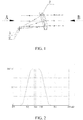
- This embodiment provides a reflective inner red dot sight optical system shown in FIG. 1 that can improve monochromaticity and concealment, which includes an LED chip 1 and a lens 3 for reflecting the light emitted from the LED chip 1 (LED light-emitting chip), a filter 2 plated with a narrow-band interference filter film is provided near the LED chip 1 and located between the LED chip 1 and the lens 3; the narrow-band filter 2 is used to filter out the light of the wider waveband except the center wavelength emitted by the LED chip 1, which improves the monochromaticity of the light waves entering the human eye and weaken the light energy emitted from the lens 3, thereby effectively avoiding being discovered and improving concealment, at the same time, the lens 3 only needs to be plated with a cutoff film for the light passing through the filter 2, so that the cutoff range of the light spectrum that enters the human eye through the lens 3 is small, and there is no obvious color loss, which improves the efficiency of the incident light, and the human eye observation is more comfortable.
- the distance between the LED chip 1 and the filter 2 is preferably in the range of 0 to 4 mm, the closer the filter 2 is to the LED light-emitting chip, the better the effect, such as 2mm, 1.5mm, 1mm, or 0.5mm or 0.2mm, and even adhere to the surface of the LED chip by optical bonding.
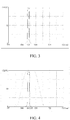
- FIG. 2 this figure shows a graph of a wavelength of the light emitted directly from the LED chip in the related art (without filter), and the light band of the emitted light is 560 ⁇ 80nm
- FIG. 3 is a graph of the wavelength when the narrow-band interference filter film is plated on the filter, and the transmitted light waveband is 545 ⁇ 8nm, and the other wavebands cannot be transmitted
- FIG. 2 shows a graph of a wavelength of the light emitted directly from the LED chip in the related art (without filter), and the light band of the emitted light is 560 ⁇ 80nm
- FIG. 3 is a graph of the wavelength when the narrow-band interference filter film is plated on the filter, and the transmitted light waveband is 545 ⁇ 8nm, and the other wavebands cannot be transmitted
- the wavelength range of the light emitted from the filter 2 is 545 ⁇ 8nm, this 545 ⁇ 8nm band will be incident on the cemented lens (lens), the wavelength range of the incident light will be narrowed, and the monochromaticity will be improved and ensured, at the same time, because of the effect of the filter, the light energy of non-central wavelength light incident on the lens is reduced or filtered, thereby reducing the light energy emitted after the lens 3, thereby avoiding being easily discovered by outsiders and improving the concealment of the sight.
- the light of the 560 ⁇ 80nm wavelength band emitted by the LED chip is incident on the cemented lens (lens), the wavelength range is wider, and the monochromaticity is reduced, since the light energy emitted from the lens is not filtered by more optical components, the spectrum of the emitted light is wider and the energy is stronger, and it is easy to be found by people looking from the direction B shown in FIG. 1 , reducing the concealment.
- FIG. 5 shows a graph of wavelength of the light passing through the cemented lens, the negative lens is in the cemented lens plated with a narrow-band interference filter film with a center wavelength of 545 ⁇ 15 nm and a long-wavelength cutoff filter film with a wavelength greater than 600 nm.
- FIG. 6 shows the superposition of the light emitted from the filter and the light emitted from the lens, it can be seen from this figure that the narrow band of green light of 545 ⁇ 8nm is reflected by the lens into the human eye, and the human eye only sees a green target image, which improves the monochromaticity. Viewing from the direction B, the light waves in the 560 ⁇ 80nm wavelength band emitted by the LED are not emitted from the lens, which improves the concealment of the sight.
- wavelength range involved in the present disclosure is not limited to the above example wavelengths, and may also be other wavelengths.
- this embodiment provides two different sights as shown in FIGS. 7 and 8 .
- This figures clearly show that the filter 2 is installed near the LED chip 1 or at the light exit hole (see FIG. 9 ) in the direction of the light path to achieve the first filtering of the wavelength of the light emitted by the LED chip 1, filter out too wide and useless wavelength band light, thereby improving the monochromaticity and light energy control, the light filtered by the filter 2 is incident on the lens 3, and then reflected again and enters the human eye, that is, side A shown in FIG. 1 . Due to the double filtering of the filter 2 and the lens 3, the light energy passing through the lens 3 is effectively reduced, thereby avoiding the perception of people at B shown in FIG. 1 , thereby enhancing the concealment of the sight.
- this embodiment provides a two-light three-color optical system shown in FIG. 10 , which includes a green light chip module 4, a red light chip module 5, and a cube prism 6; the green light chip module 4 and the red light chip module 5 are arranged perpendicular to each other, and they are independent of each other, through controlling the circuit, the emitted green light or red light can be shared, in order to generate the third color light, in this embodiment, the geometric center of the cube prism 6 is arranged at the intersection of the light emitted from the green light chip module 4 and the red light chip module 5, and the diagonal surface 8 of the cube prism 6 extending along the angle bisector of the angle between the light emitted from green light chip module 4 and the red light chip module 5 is plated with a composite film, the composite film is used to totally reflect the emitted red light of the red light chip module 5 and transmit the emitted green
- the incident surface A of the cube prism 6 perpendicular to the emitted light of the green chip module is plated with a narrow-band transmission film that transmits light with a wavelength of 545 nm to ensure that the required wavelength range of green light is emitted through the cube prism 6 without loss.
- the incident surface C and the exit surface B (the side opposite to the incident surface A is the exit surface B) perpendicular to the emitted red light of the red light chip module 5 are coated with a broadband anti-reflection coating to ensure that the red light and green light are emitted through the cube prism 6 without loss.
- this embodiment provides the sight shown in FIGS. 11 and 12 , which is installed on the LED mounting base 7 at the rear end of the body 11, the green light chip module 4 is installed on the front end surface of the LED mounting base 7, and the red light chip module 5 is installed on the front end side of the LED mounting base 7 through an LED base 9; the installation plane of the LED base 9 is perpendicular to the front end surface of the LED mounting base 7. This ensures that the red light and the green light overlap each other to produce the third color light.
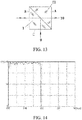
- the cube prism 6 involved in the above described embodiment is formed by gluing two isosceles right-angle prisms (including isosceles right-angle prism I and isosceles right-angle prism II), the diagonal surface 8 is the cemented surface, the surfaces B and C of the cube prism 6 are both plated with a broad-band anti-reflection film with a wavelength of 400 to 800 nm; where, the adjacent surface A, which is perpendicular to the surface C, is plated with a narrow-band transmission film that transmits light with a wavelength of 545nm.
- Surface A and surface C are the light incident surfaces of the green light chip module 4 and the red light chip module 5 respectively; the surface B is the light exit surface, after the light emitted from the green light chip module 4 and the red light chip module 5 passing through the diagonal surface 8, that is, the cemented surface, the light exit from the surface B.
- the cemented surface is plated with a film that reflects light greater than 600nm as shown in FIG. 14 .
- the surfaces A and B of the isosceles right-angle prism I are plated with a broad-band anti-reflection film with a wavelength of 400 to 800 nm as shown in FIG. 16 .
- the cemented lens 14 is composed of positive and negative lens, the positive and negative lens are arranged in the order of distance from the cube prism 6 from far to near; the negative lens is plated with a narrow-band interference filter film with a center wavelength of 545 ⁇ 15nm and a long-wavelength cutoff filter film with a wavelength greater than 600 nm. Therefore, when the light emitted by the red and green light chip modules is incident on the reflective surface of the cemented lens 14, that is, the negative lens.
- the negative lens is plated with a narrow-band interference filter film and a long-wavelength cutoff filter film as shown in the graph of the FIG.
- the light of the corresponding wavelength is reflected back to the eyepiece along the observation direction of the human eye, and the green light pattern or the red light pattern can be observed, and a yellow pattern composed of red and green light can also be observed, suitable for use in different aiming background environments.
Landscapes
- Physics & Mathematics (AREA)
- Optics & Photonics (AREA)
- Engineering & Computer Science (AREA)
- General Engineering & Computer Science (AREA)
- Optical Elements Other Than Lenses (AREA)
- Optical Filters (AREA)
- Telescopes (AREA)
- Led Device Packages (AREA)
- Lenses (AREA)
Applications Claiming Priority (2)
| Application Number | Priority Date | Filing Date | Title |
|---|---|---|---|
| CN201910028904.8A CN111435063B (zh) | 2019-01-12 | 2019-01-12 | 一种提高单色性和隐蔽性的反射式内红点瞄准镜光学系统 |
| PCT/CN2019/130414 WO2020143504A1 (zh) | 2019-01-12 | 2019-12-31 | 提高单色性和隐蔽性的反射式内红点瞄准镜光学系统、双光三色光学系统及其瞄具 |
Publications (4)
| Publication Number | Publication Date |
|---|---|
| EP3896383A1 true EP3896383A1 (de) | 2021-10-20 |
| EP3896383A4 EP3896383A4 (de) | 2022-08-31 |
| EP3896383B1 EP3896383B1 (de) | 2025-10-08 |
| EP3896383C0 EP3896383C0 (de) | 2025-10-08 |
Family
ID=71520862
Family Applications (1)
| Application Number | Title | Priority Date | Filing Date |
|---|---|---|---|
| EP19908320.5A Active EP3896383B1 (de) | 2019-01-12 | 2019-12-31 | Optisches system mit reflektivem innerem rotpunktvisier mit verbesserter monochromatizität und verdeckung, optisches system mit zwei lichtern und drei farben und visier dafür |
Country Status (6)
| Country | Link |
|---|---|
| US (1) | US11802751B2 (de) |
| EP (1) | EP3896383B1 (de) |
| JP (2) | JP2022518006A (de) |
| CN (1) | CN111435063B (de) |
| ES (1) | ES3053184T3 (de) |
| WO (1) | WO2020143504A1 (de) |
Families Citing this family (2)
| Publication number | Priority date | Publication date | Assignee | Title |
|---|---|---|---|---|
| EP4443098A1 (de) * | 2021-12-02 | 2024-10-09 | Huanic Corporation | Sichtsystem auf basis einer kombination aus infrarotbildgebung, bildgebung mit geringer beleuchtung und led-visierlichtpunkt sowie sicht mit thermischer bildgebungsfunktion |
| CN218769589U (zh) * | 2022-04-07 | 2023-03-28 | 西安华科光电有限公司 | 一种设置有滤光膜的半导体发光二极管及瞄准镜光学系统 |
Family Cites Families (25)
| Publication number | Priority date | Publication date | Assignee | Title |
|---|---|---|---|---|
| FR2443695B1 (fr) * | 1978-12-04 | 1986-02-21 | Vannet Gresset Germaine | Objectif de viseur |
| DE4336956B4 (de) * | 1993-10-29 | 2007-04-12 | Carl Zeiss Sports Optics Gmbh | Visiereinrichtung |
| JP2005005217A (ja) | 2003-06-13 | 2005-01-06 | Seiko Epson Corp | 発光素子、照明装置、投射型表示装置 |
| JP4402050B2 (ja) | 2006-01-13 | 2010-01-20 | 宜蓉 李 | レッドドットサイトの装置及び照準方法 |
| US7506468B2 (en) * | 2006-08-02 | 2009-03-24 | Michael Anthony Farrell | Method and apparatus for monitoring handling of a firearm |
| JP4078378B2 (ja) | 2006-10-17 | 2008-04-23 | ロッキード マーティン コーポレイション | 一体型レーザ/赤外線前方監視光学装置 |
| DE102007063407A1 (de) * | 2007-12-31 | 2009-07-02 | Schmidt & Bender Gmbh & Co. Kg | Reflexvisier |
| US8215050B2 (en) * | 2008-10-02 | 2012-07-10 | Trijicon, Inc. | Optical sight |
| CN201340455Y (zh) * | 2009-01-16 | 2009-11-04 | 南京信息工程大学 | 振动拉曼激光雷达散射光处理系统 |
| JP5335584B2 (ja) | 2009-07-09 | 2013-11-06 | 株式会社 ニコンビジョン | レチクルユニット及び光学機器 |
| US20110228366A1 (en) | 2010-03-22 | 2011-09-22 | Shou LIU | Hoe optical system for holographic sight |
| SE536566C2 (sv) * | 2010-04-01 | 2014-02-25 | Gs Dev Ab | Aggregat omfattande en förstoringsanordning och ett därvid monterat spatialspektralfilter |
| US8621759B2 (en) * | 2010-11-10 | 2014-01-07 | Raytheon Canada Limited | Method and system for attenuating a wavelength shifting source |
| JP2013252413A (ja) | 2011-12-13 | 2013-12-19 | Mignon Belle:Kk | 平面パネル型狭帯域単色光照射装置および砲弾型led狭帯域単色光照射装置 |
| JP5778217B2 (ja) | 2013-07-02 | 2015-09-16 | 株式会社東和電機製作所 | 集魚灯 |
| CN104280806A (zh) * | 2013-07-12 | 2015-01-14 | 长春理工大学 | 超宽波段高截止窄带干涉滤光镜 |
| KR102141049B1 (ko) * | 2013-12-13 | 2020-08-04 | 정보선 | 빔 스플리터를 구비한 도트 사이트 장치 |
| KR101712720B1 (ko) * | 2015-03-03 | 2017-03-07 | 한국광기술원 | 광학식 조준경 |
| JP6531901B2 (ja) | 2015-05-22 | 2019-06-19 | セイコーエプソン株式会社 | 照明装置およびプロジェクター |
| CN204806974U (zh) * | 2015-06-03 | 2015-11-25 | 陈巧珍 | 滤光反射瞄准镜 |
| CN106197147B (zh) * | 2016-08-25 | 2017-10-20 | 河南华阳装备制造有限公司 | 多功能快速瞄准枪械瞄准镜 |
| JP2018180031A (ja) | 2017-04-04 | 2018-11-15 | 株式会社東京スコープ | ドットサイト |
| CN208139945U (zh) * | 2018-04-26 | 2018-11-23 | 厦门大学 | 一种瞄准线可变式全息瞄准镜 |
| CN108873135A (zh) | 2018-08-06 | 2018-11-23 | 信阳舜宇光学有限公司 | 一种近红外窄带滤光片及红外成像系统 |
| CN209926991U (zh) * | 2019-01-12 | 2020-01-10 | 西安华科光电有限公司 | 一种提高单色性和隐蔽性的反射式内红点瞄准镜光学系统 |
-
2019
- 2019-01-12 CN CN201910028904.8A patent/CN111435063B/zh active Active
- 2019-12-31 EP EP19908320.5A patent/EP3896383B1/de active Active
- 2019-12-31 JP JP2021540414A patent/JP2022518006A/ja active Pending
- 2019-12-31 ES ES19908320T patent/ES3053184T3/es active Active
- 2019-12-31 WO PCT/CN2019/130414 patent/WO2020143504A1/zh not_active Ceased
- 2019-12-31 US US17/418,670 patent/US11802751B2/en active Active
-
2022
- 2022-12-05 JP JP2022194122A patent/JP7454631B2/ja active Active
Also Published As
| Publication number | Publication date |
|---|---|
| CN111435063A (zh) | 2020-07-21 |
| EP3896383A4 (de) | 2022-08-31 |
| EP3896383B1 (de) | 2025-10-08 |
| WO2020143504A1 (zh) | 2020-07-16 |
| US20220074704A1 (en) | 2022-03-10 |
| JP7454631B2 (ja) | 2024-03-22 |
| US11802751B2 (en) | 2023-10-31 |
| JP2022518006A (ja) | 2022-03-11 |
| EP3896383C0 (de) | 2025-10-08 |
| JP2023014379A (ja) | 2023-01-26 |
| CN111435063B (zh) | 2024-07-09 |
| ES3053184T3 (en) | 2026-01-20 |
Similar Documents
| Publication | Publication Date | Title |
|---|---|---|
| EP3754408B1 (de) | Am körper tragbares ar-system und ar-anzeigevorrichtung und projektionsquellenmodul dafür | |
| US9395542B2 (en) | Projecting synthetic imagery and scenic imagery using an optical component comprising a diffractive optical element pattern | |
| CN105980808B (zh) | 点瞄准装置 | |
| CN101598294A (zh) | 准直透镜、照明单元及投影系统 | |
| EP3579039A1 (de) | Projektionsvorrichtung und kopfmontierte anzeigevorrichtung | |
| US11802751B2 (en) | Reflective inner red dot sight optical system with improved monochromaticity and concealment, two-light three-color optical system, and sight thereof | |
| US20140036364A1 (en) | Regular pentagon-arranged optical beam splitting and combining assembly | |
| CN113970833A (zh) | 光学模组和电子设备 | |
| TWI489855B (zh) | 立體投影光源系統 | |
| CN114488538A (zh) | Ar光机和头戴显示设备 | |
| US20210149183A1 (en) | Virtual image projection device | |
| CN112799234B (zh) | 合色装置及其方法和照明系统 | |
| CN209926991U (zh) | 一种提高单色性和隐蔽性的反射式内红点瞄准镜光学系统 | |
| CN112839150B (zh) | 一种基于Philips棱镜结构的日夜兼用摄像系统及摄像机 | |
| JP2025129223A (ja) | 熱画像機能付きの照準器 | |
| CN211669454U (zh) | 测距仪光路分合棱镜模块装置 | |
| KR102188701B1 (ko) | 빔 스플리터를 구비한 도트 사이트 장치 | |
| CN209746340U (zh) | 一种单通道双图案的投影系统 | |
| CN218769589U (zh) | 一种设置有滤光膜的半导体发光二极管及瞄准镜光学系统 | |
| CN211601732U (zh) | 一种双光三色光学系统及其瞄具 | |
| CN113063318A (zh) | 一种双光三色光学系统及其瞄具 | |
| CN116893514A (zh) | 显示装置和复合显示装置 | |
| CN113970853A (zh) | 光学模组和电子设备 | |
| CN119033320B (zh) | 一种胃肠镜的照明系统和胃肠镜 | |
| US20240411144A1 (en) | Combined sighting system and optical system thereof |
Legal Events
| Date | Code | Title | Description |
|---|---|---|---|
| STAA | Information on the status of an ep patent application or granted ep patent |
Free format text: STATUS: THE INTERNATIONAL PUBLICATION HAS BEEN MADE |
|
| PUAI | Public reference made under article 153(3) epc to a published international application that has entered the european phase |
Free format text: ORIGINAL CODE: 0009012 |
|
| STAA | Information on the status of an ep patent application or granted ep patent |
Free format text: STATUS: REQUEST FOR EXAMINATION WAS MADE |
|
| 17P | Request for examination filed |
Effective date: 20210715 |
|
| AK | Designated contracting states |
Kind code of ref document: A1 Designated state(s): AL AT BE BG CH CY CZ DE DK EE ES FI FR GB GR HR HU IE IS IT LI LT LU LV MC MK MT NL NO PL PT RO RS SE SI SK SM TR |
|
| DAV | Request for validation of the european patent (deleted) | ||
| DAX | Request for extension of the european patent (deleted) | ||
| REG | Reference to a national code |
Ref country code: DE Ref legal event code: R079 Free format text: PREVIOUS MAIN CLASS: F41G0001360000 Ipc: F41G0001300000 Ref country code: DE Ref legal event code: R079 Ref document number: 602019076754 Country of ref document: DE Free format text: PREVIOUS MAIN CLASS: F41G0001360000 Ipc: F41G0001300000 |
|
| A4 | Supplementary search report drawn up and despatched |
Effective date: 20220801 |
|
| RIC1 | Information provided on ipc code assigned before grant |
Ipc: F41G 1/30 20060101AFI20220726BHEP |
|
| GRAP | Despatch of communication of intention to grant a patent |
Free format text: ORIGINAL CODE: EPIDOSNIGR1 |
|
| STAA | Information on the status of an ep patent application or granted ep patent |
Free format text: STATUS: GRANT OF PATENT IS INTENDED |
|
| INTG | Intention to grant announced |
Effective date: 20250519 |
|
| GRAS | Grant fee paid |
Free format text: ORIGINAL CODE: EPIDOSNIGR3 |
|
| GRAA | (expected) grant |
Free format text: ORIGINAL CODE: 0009210 |
|
| STAA | Information on the status of an ep patent application or granted ep patent |
Free format text: STATUS: THE PATENT HAS BEEN GRANTED |
|
| AK | Designated contracting states |
Kind code of ref document: B1 Designated state(s): AL AT BE BG CH CY CZ DE DK EE ES FI FR GB GR HR HU IE IS IT LI LT LU LV MC MK MT NL NO PL PT RO RS SE SI SK SM TR |
|
| REG | Reference to a national code |
Ref country code: GB Ref legal event code: FG4D Ref country code: CH Ref legal event code: F10 Free format text: ST27 STATUS EVENT CODE: U-0-0-F10-F00 (AS PROVIDED BY THE NATIONAL OFFICE) Effective date: 20251008 |
|
| REG | Reference to a national code |
Ref country code: IE Ref legal event code: FG4D |
|
| U01 | Request for unitary effect filed |
Effective date: 20251008 |
|
| U07 | Unitary effect registered |
Designated state(s): AT BE BG DE DK EE FI FR IT LT LU LV MT NL PT RO SE SI Effective date: 20251013 |
|
| U1N | Appointed representative for the unitary patent procedure changed after the registration of the unitary effect |
Representative=s name: LORENZ SEIDLER GOSSEL PART. MBB; DE |
|
| PGFP | Annual fee paid to national office [announced via postgrant information from national office to epo] |
Ref country code: GB Payment date: 20251229 Year of fee payment: 7 |
|
| PGFP | Annual fee paid to national office [announced via postgrant information from national office to epo] |
Ref country code: TR Payment date: 20251215 Year of fee payment: 7 |
|
| REG | Reference to a national code |
Ref country code: ES Ref legal event code: FG2A Ref document number: 3053184 Country of ref document: ES Kind code of ref document: T3 Effective date: 20260120 |
|
| U20 | Renewal fee for the european patent with unitary effect paid |
Year of fee payment: 7 Effective date: 20251223 |