EP3894730B1 - Fire safety sleeve segment and fire safety sleeve - Google Patents
Fire safety sleeve segment and fire safety sleeve Download PDFInfo
- Publication number
- EP3894730B1 EP3894730B1 EP19806243.2A EP19806243A EP3894730B1 EP 3894730 B1 EP3894730 B1 EP 3894730B1 EP 19806243 A EP19806243 A EP 19806243A EP 3894730 B1 EP3894730 B1 EP 3894730B1
- Authority
- EP
- European Patent Office
- Prior art keywords
- fire protection
- housing element
- protection sleeve
- intumescent material
- fire
- Prior art date
- Legal status (The legal status is an assumption and is not a legal conclusion. Google has not performed a legal analysis and makes no representation as to the accuracy of the status listed.)
- Active
Links
- 239000000463 material Substances 0.000 claims description 77
- 229910052751 metal Inorganic materials 0.000 claims description 25
- 239000002184 metal Substances 0.000 claims description 25
- 238000005452 bending Methods 0.000 claims description 22
- OKTJSMMVPCPJKN-UHFFFAOYSA-N Carbon Chemical compound [C] OKTJSMMVPCPJKN-UHFFFAOYSA-N 0.000 claims description 7
- 229910002804 graphite Inorganic materials 0.000 claims description 7
- 239000010439 graphite Substances 0.000 claims description 7
- 238000007789 sealing Methods 0.000 claims description 5
- 230000000149 penetrating effect Effects 0.000 description 5
- 230000008901 benefit Effects 0.000 description 3
- 239000000779 smoke Substances 0.000 description 3
- 238000002679 ablation Methods 0.000 description 2
- 239000003795 chemical substances by application Substances 0.000 description 2
- 238000004519 manufacturing process Methods 0.000 description 2
- 230000006641 stabilisation Effects 0.000 description 2
- 238000011105 stabilization Methods 0.000 description 2
- 239000004114 Ammonium polyphosphate Substances 0.000 description 1
- 229920000877 Melamine resin Polymers 0.000 description 1
- MXRIRQGCELJRSN-UHFFFAOYSA-N O.O.O.[Al] Chemical compound O.O.O.[Al] MXRIRQGCELJRSN-UHFFFAOYSA-N 0.000 description 1
- 239000004743 Polypropylene Substances 0.000 description 1
- 229910000831 Steel Inorganic materials 0.000 description 1
- 239000002535 acidifier Substances 0.000 description 1
- 229940095602 acidifiers Drugs 0.000 description 1
- 230000009471 action Effects 0.000 description 1
- 230000004913 activation Effects 0.000 description 1
- 239000000654 additive Substances 0.000 description 1
- 230000032683 aging Effects 0.000 description 1
- 235000019826 ammonium polyphosphate Nutrition 0.000 description 1
- 229920001276 ammonium polyphosphate Polymers 0.000 description 1
- 239000002956 ash Substances 0.000 description 1
- 238000010276 construction Methods 0.000 description 1
- 230000000694 effects Effects 0.000 description 1
- 230000002349 favourable effect Effects 0.000 description 1
- 239000003063 flame retardant Substances 0.000 description 1
- 239000006260 foam Substances 0.000 description 1
- 238000009434 installation Methods 0.000 description 1
- 230000007246 mechanism Effects 0.000 description 1
- JDSHMPZPIAZGSV-UHFFFAOYSA-N melamine Chemical compound NC1=NC(N)=NC(N)=N1 JDSHMPZPIAZGSV-UHFFFAOYSA-N 0.000 description 1
- 230000035515 penetration Effects 0.000 description 1
- 239000004033 plastic Substances 0.000 description 1
- 229920000642 polymer Polymers 0.000 description 1
- 229920005862 polyol Polymers 0.000 description 1
- 150000003077 polyols Chemical class 0.000 description 1
- -1 polypropylene Polymers 0.000 description 1
- 229920001155 polypropylene Polymers 0.000 description 1
- 239000003380 propellant Substances 0.000 description 1
- 239000011814 protection agent Substances 0.000 description 1
- 230000007480 spreading Effects 0.000 description 1
- 239000010959 steel Substances 0.000 description 1
Images


Classifications
-
- A—HUMAN NECESSITIES
- A62—LIFE-SAVING; FIRE-FIGHTING
- A62C—FIRE-FIGHTING
- A62C2/00—Fire prevention or containment
- A62C2/06—Physical fire-barriers
- A62C2/065—Physical fire-barriers having as the main closure device materials, whose characteristics undergo an irreversible change under high temperatures, e.g. intumescent
-
- F—MECHANICAL ENGINEERING; LIGHTING; HEATING; WEAPONS; BLASTING
- F16—ENGINEERING ELEMENTS AND UNITS; GENERAL MEASURES FOR PRODUCING AND MAINTAINING EFFECTIVE FUNCTIONING OF MACHINES OR INSTALLATIONS; THERMAL INSULATION IN GENERAL
- F16L—PIPES; JOINTS OR FITTINGS FOR PIPES; SUPPORTS FOR PIPES, CABLES OR PROTECTIVE TUBING; MEANS FOR THERMAL INSULATION IN GENERAL
- F16L5/00—Devices for use where pipes, cables or protective tubing pass through walls or partitions
- F16L5/02—Sealing
- F16L5/04—Sealing to form a firebreak device
Definitions
- the invention relates to a fire protection collar segment and a fire protection collar composed of a plurality of fire protection collar segments for sealing off a combustible body penetrating an opening in a wall or ceiling in the event of a fire.
- Various fire protection means are used to provide fire protection, for example in the form of inserts that are attached to an enclosure.
- Intumescent materials in particular are suitable as fire retardants. In the event of a fire, the intumescent material foams up due to the effect of heat and closes the opening, preventing or at least delaying the spread of smoke or fire.
- Fire protection collars have the advantage that they are mounted outside the opening in front of the wall and can therefore be heated up more quickly in the event of a fire, since the fire protection agent is not passively cooled by the surrounding wall.
- a fire protection device which is composed of several housing segments, whereby the diameter of the finished fire protection device can be adapted to the respective pipe.
- Such a system is only suitable for smaller pipe diameters, since the size of the individual housing segment must be matched to the smallest pipe diameter to be expected. As a result, with larger pipe diameters, there is not enough fire protection material to ensure that the entire opening is closed.
- the object of the invention is therefore to provide a fire protection device that can be used flexibly and is at the same time inexpensive.
- a fire protection collar segment for a fire protection collar for sealing a combustible body penetrating an opening in a wall or ceiling in the event of fire with a first housing element and a second housing element which is firmly connected to the first housing element, the housing elements each having a boundary wall with a contact surface and an outer surface opposite the contact surface, the two housing elements being arranged in steps relative to one another, and with an intumescent material being applied to the contact surfaces, characterized in that the first housing element has a first end wall which is connected to the second by a predetermined bending edge Housing element fixed, preferably in one piece, is connected.
- a fire protection sleeve can be assembled from several of these fire protection sleeve segments and thus be adapted to a desired pipe diameter.
- the stepped arrangement of the housing elements of the fire protection sleeve segment ensures that several of the fire protection sleeve segments can be arranged at a variable distance from one another and at the same time in a stable manner. Furthermore, arrangements can be achieved that require less intumescent material, since the amount of intumescent material can be varied by shifting the sleeve segments depending on the pipe diameter.
- each fire sleeve segment can be obtained by stamping from a metal plate using the same tool.
- the intumescent material expands and thus closes the opening as soon as the combustible body penetrating the opening collapses.
- the application of the intumescent material to the contact surfaces facing the combustible body ensures that it is already pointing in the direction of the opening to be closed.
- the first housing element has a first end wall, which can be arranged essentially perpendicularly, ie at an angle of approximately 90° ⁇ 15°, to the boundary wall and bounds the intumescent material applied to the contact surface.
- the first end wall is firmly connected, preferably in one piece, to the boundary wall of the second housing element via a first predetermined bending edge. In this way, the second housing element can move at the first predetermined bending edge under the action of force. Due to the stepwise arrangement of the housing elements, the second housing element lies above the first housing element of an adjacent fire protection collar segment in the application.
- the intumescent material contained by the first housing element can inflate in the event of a fire and act on the second housing element of the adjacent fire protection collar segment and actively move this into the center of the opening to be sealed.
- a larger tube opening can also be filled more quickly with intumescent material be closed, since this is transported by the movement of the second housing member towards the center of the pipe opening.
- the one-piece embodiment ensures a stable connection between the first and the second housing element, and the individual segments can be manufactured easily, for example by means of stamping.
- the first housing element can have a tab on its outer surface.
- the first housing element can have a band, preferably a metal band, on the side of the boundary wall opposite the first end wall, more preferably a metal band integrally connected to the boundary wall.
- the metal strip preferably protrudes in the longitudinal direction of the boundary wall and can be guided into the tab of the first housing element of an adjacent fire protection sleeve segment and attached to it. This provides a simple way of connecting multiple fire protection collar segments to form a fire protection collar.
- the metal strip has recesses on at least one edge or is provided with perforations at which the metal strip can be bent. This creates a simple way of attaching the metal strip to the tab and fixing it in its position relative to the adjacent fire protection sleeve segment. By introducing a large number of perforations along the direction in which the metal strip extends, the distance between the fire protection collar segments connected to one another can be set in a targeted manner, since the metal strip can be bent at each of these perforations.
- the metal strip can have bumps on its surface, preferably ribs or other latching elements. These bumps can catch on the tab of the adjacent fire protection sleeve segment like a cable tie and thus create a secure connection.
- the first housing element can also have a second end wall which is also substantially perpendicular, ie at an angle of approximately 90° ⁇ 15°, to the Boundary wall is arranged and the first end wall is opposite.
- the second end wall is preferably firmly connected, preferably in one piece, to a first panel via a second predetermined bending edge, the first panel being arranged at least partially over the intumescent material on the contact surface of the first housing element.
- the first screen at least partially covers the intumescent material applied to the contact surface of the first housing element.
- the intumescent material is thus additionally secured mechanically by the first panel, which means that material loss, for example as a result of aging processes, can be prevented.
- the second predetermined bending edge ensures that the panel can be folded over easily and, on the other hand, that the intumescent material on the contact surface of the first housing element, which expands in the event of a fire, pushes the panel to the side and spreads unhindered into the opening to be closed can.
- the first panel can act on the second housing element of the adjacent fire protection collar segment, which is located above the panel, and press it in the direction of the center of the opening.
- a side wall is preferably arranged at an angle of approximately 90° ⁇ 15° to the boundary wall of the first housing element, which side wall adjoins the first and optionally the second end wall and which delimits the intumescent material on the side of the housing element which is remote from the wall or ceiling in the application .
- an attachment element can be attached to the outer surface of the boundary wall of the first housing element.
- the fastening element preferably has a recess through which a suitable fastening means can be guided.
- the fastening element is arranged on the side of the housing element that faces the wall or ceiling in the application and protrudes from the outer surface of the boundary wall in a direction away from the combustible body.
- the housing element can be screwed or riveted to the wall or ceiling, for example, with the aid of the fastening element.
- the first housing element can have a projection on its outer surface, preferably at the height of the fastening element exhibit.
- the fastening element of the individual fire protection sleeve segments can be designed in such a way that the recess can be pushed onto the projection of the axially adjacent fire protection sleeve segment, and a secure connection is thereby established between the two fire protection sleeve segments.
- the second housing element can have a third end wall which is opposite the first predetermined bending edge and which is essentially perpendicular, ie. H. is arranged at an angle of approximately 90° ⁇ 15° to the boundary wall of the second housing element and limits the intumescent material applied to the contact surface of the second housing element.
- the third end wall is preferably firmly connected, preferably in one piece, to a second screen, the second screen at least partially covering the intumescent material on the contact surface of the second housing element, and a third predetermined bending edge preferably being provided between the second screen and the third end wall.
- the intumescent material can be mechanically secured on the contact surface of the second housing element with the second screen.
- the third predetermined bending edge ensures that, in the event of a fire, the panel bends sideways in the direction of the opening to be closed due to the intumescent material expanding on the contact surface of the second housing element, so that the intumescent material can close the opening unhindered.
- the screen which is bent towards the center of the combustible body in the event of a fire, ensures mechanical stabilization of the expanded intumescent material. As a result, the opening is closed more securely on the one hand, and on the other hand less intumescent material can be used with the opening being closed in the same stable manner.
- an intumescent material can also be applied to the second screen, preferably at least on its side facing the contact surface of the second housing element.
- the second aperture is not only used for mechanical stabilization used, but also introduces additional intumescent material into the opening to be closed.
- the second housing element preferably also has a side wall which is essentially perpendicular, ie. H. at an angle of about 90° ⁇ 15°, to the boundary wall of the second housing element and which is adjacent to the third end wall.
- the intumescent material on the contact surface of the second housing element is delimited by the side wall on the side of the housing element that faces away from the wall or ceiling in the application.
- the intumescent material can include or consist of expandable graphite.
- Expandable graphite is an inexpensive intumescent material and also has particularly favorable properties. Thus, in the event of a fire, the expandable graphite develops a sufficiently large force that can cause the second housing element and/or the first and the second screen to move in the direction of the opening to be closed.
- expanded expandable graphite is largely temperature-resistant and thus creates a secure seal in the event of a fire.
- the intumescent material can include other additives known in the prior art, such as propellants, acidifiers, ash formers and ablation agents.
- the fire protection sleeve segments according to the invention can be easily assembled to form a fire protection sleeve which can be placed around the combustible body penetrating the opening in the wall or ceiling.
- the subject matter of the invention is therefore also a fire protection collar, comprising several of the fire protection collar segments described above, characterized in that the fire protection collar segments are arranged relative to one another in such a way that the intumescent material applied to the contact surface of the first housing element is at least partially covered by the second housing element of an adjacent fire protection collar segment.
- the adjacent fire protection sleeve segments are arranged without any spacing from one another, so that the second housing element comes to lie flush over the first housing element of an adjacent fire protection sleeve segment.
- This embodiment is achieved by arranging the first and second housing members of each in a stepped manner Fire protection sleeve segment allows. Since at least two layers of the intumescent material are always on top of one another in this way, even large openings can be closed in the event of a fire.
- the second housing element is advantageously moved in the direction of the opening to be closed by the inflating intumescent material of the underlying first housing element of the adjacent fire protection collar segment.
- a fire protection collar which comprises several of the fire protection collar segments described above, the fire protection collar segments are arranged at a distance from one another, so that at least part of the intumescent material applied to the contact surface of the first housing element is not covered by the second housing element of the respectively adjacent fire protection collar segment.
- Such a stretched arrangement offers the advantage that, particularly in the case of smaller openings, two or more layers of the intumescent material do not have to lie one on top of the other at every point of the fire protection collar, while at the same time ensuring that at least one layer of the intumescent material is present at each point of the opening for fire protection sufficient quantity is available. This allows a significant saving in material to be achieved.
- the invention relates to the use of a fire protection collar according to the above-described embodiments for sealing a combustible body penetrating an opening in a wall or ceiling in the event of fire, the fire protection collar being arranged around the combustible body in such a way that the intumescent material rests on the contact surfaces of the first and second Housing element facing the body and the respective outer surfaces of the boundary walls from combustible bodies are turned away, and wherein several layers of intumescent material are arranged one behind the other at least in sections.
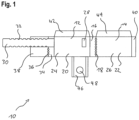
- FIG 1 shows a housing for a fire protection sleeve segment 10 according to the invention in the form of a stamped part, with a first housing element 12 and a second housing element 14, the first housing element 12 and the second housing element 14 being fixed to a first predetermined bending edge 18 via a first end wall 16 of the first housing element 12 are connected to each other.
- the first housing member 12 and the second housing member 14 each have a boundary wall 20 and 22, respectively, with an outer surface 24 and 26, respectively.
- a tab 28 is located on the outer surface 24 of the first housing member 12.
- a metal strip 30 connected to the boundary wall 20 and protruding from the first housing element 12 in the longitudinal direction thereof.
- the metal strip 30 has perforations 32 at its edges, at which the metal strip 30 can be bent.
- the first housing element 12 also has, on its side opposite the first end wall 16 , a second end wall 34 which is connected to a first panel 38 via a second predetermined bending edge 36 . According to an alternative embodiment, the first housing element 12 can only have the metal strip 30 on this side.
- first side wall 42 or a second side wall 44 is provided on the first housing element 12 and on the second housing element 14 .
- a fastening element 46 with a recess 48 protrudes from the first housing element 12 in its transverse direction.
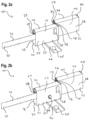
- FIG 2a a fire protection collar segment is shown as it is made from an analogous to figure 1 manufactured stamped part can be folded.
- the first housing element 12 and the second housing element 14 are arranged in steps relative to one another.
- the step is formed at the first predetermined bending edge 18 between the first housing element 12 and the second housing element 14 .
- the first end wall 16 is arranged essentially perpendicularly to the boundary wall 20 and thus delimits a contact surface 50 on the first housing element 12.
- the third end wall 40 is essentially perpendicular to the boundary wall 22 and delimits the contact surface 52 on the second housing element 14.
- the side walls 42 and 44 are also bent up in such a way that they are essentially perpendicular to the delimiting surfaces 20 and 22 and delimit the contact surfaces 50 and 52 .
- An intumescent material 54 or 56 is applied to the contact surfaces 50 and 52 of the first housing element 12 or the second housing element 14, respectively.
- the intumescent material 54 and 56 can be glued to the contact surfaces 50 and 52, for example.
- the intumescent material in the illustrated embodiment comprises expandable graphite.
- other fire protection materials are also conceivable, for example polymer-bound intumescent materials based on melamine, ammonium polyphosphate and polyols, optionally together with expandable graphite and/or ablation agents such as aluminum trihydroxide.
- the second end wall 34 on the first housing element 12 is bent up in such a way that it faces the first end wall 16 and that the first screen 38 comes to lie over the intumescent material 56 in the first housing element 12 .
- first end wall 16, the second end wall 34 and the third end wall 40 are designed so wide that they cover the intumescent material 54 or 56 laterally. In this way, the intumescent material 54 or 56 is prevented from falling out laterally.
- the second end wall 34 has a recess which corresponds to the width of the metal strip 30 . This is due to the fact that the housing of the fire protection collar segment 10 has been produced as a stamped part. If the metal strip 30 is manufactured individually and then attached to the first housing element 12, for example welded or soldered, the second end wall 34 can also completely cover the intumescent material 54.
- the fastening element 46 is arranged perpendicular to the outer surface 24 of the first housing element 12 . In this way, the fastening element 46 can be attached, for example screwed, to a wall or ceiling through which an opening 58 runs.
- FIG Figure 2b An alternative embodiment of the fire protection sleeve segment 10 is shown in FIG Figure 2a 1, in which the first housing element 12 additionally has a projection 60 on its outer surface 24. This is arranged so that the recess 48 of the fastener 46 of a second fire protection collar segment 10, which is stacked axially over the first fire protection collar segment 10, could be anchored to the projection 60 of the first fire protection collar segment 10. The fastening element 46 of the second fire protection sleeve segment would then lie approximately in one plane with the boundary wall 20 . In this way, two fire protection sleeve segments 10, which are arranged axially one on top of the other, can be connected to one another by means of the fastening element 46.
- the fastener 46 may be provided at various positions relative to the tab 28 on the first housing member 12, as shown in FIG figure 1 and Figure 2b shown. If a projection 60 is provided, the fastening element 46 is advantageously not attached at the level of the lug 28, so that a secure connection between the fastening element 46 and a projection 60 on the outer surface 20 of the first housing element 12 arranged axially below the second fire protection collar segment 10 is ensured.
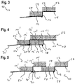
- FIG 3 1 is a schematic sectional view of an embodiment of the fire protection sleeve segment 10, in which only the first end wall 16 is shown.
- the two housing elements 12 and 14 are stepped to each other arranged and each have an intumescent material 54 and 56 on their contact surfaces 50 and 52, respectively.
- FIG 4 are two of the in figure 3 shown fire protection sleeve segments arranged in a space-free position to each other.
- the metal band 30 of the first fire protection collar segment 10 engages in the tab 28' of the adjacent fire protection collar segment 10' and thus ensures a secure connection of the two fire protection collar segments 10 and 10'.
- the metal strip 30 is in the in figure 4 shown embodiment is not bent over, but has bumps (not shown) on its surface, for example ribs or locking elements, which hook into the tab 28' and thus ensure a secure connection.
- figure 5 shows a stretched arrangement of two fire protection sleeve segments 10 and 10', in which the fire protection sleeve segments 10 and 10' are arranged at a distance from one another, and in which the second housing element 14' of the fire protection sleeve segment 10' only partially has the intumescent material 54 on the first housing element 12 of the fire protection sleeve segment 10 is covered.
- firestop collars 62 positioned in front of a wall (not shown) around an opening 58 of a combustible body 64 and comprising a plurality of firestop collar segments 10 connected together.
- the combustible body 64 is preferably a pipe, in particular a plastic pipe, or a cable duct.
- fire protection sleeve segments 10 For assembly, several of the fire protection sleeve segments 10 are firmly connected to one another by means of the metal strips 30 , the number of fire protection sleeve segments 10 used being adapted to the diameter of the combustible body 64 .
- the chain of fire protection collar segments 10 thus formed is then placed around the combustible body 64 and the terminal fire protection collar segments 10 are connected by means of the metal strip 30 .
- the fastening elements 46 protrude substantially perpendicularly from the boundary wall 20 and are applied to the wall (not shown) and then firmly connected to the wall, for example screwed. In this way, the firestop collar 62 is securely fixed to the wall around the combustible body 64 .
- the stepped fire protection collar segments 10 are arranged around the combustible body 64 in such a way that the contact surfaces 50 and 52, and thus also the intumescent material 54 and 56, point in the direction of the combustible body 64.
- the outer surfaces 24 and 26 of the boundary walls 20 and 22 point away from the combustible body 64, respectively.
- the side walls 42 and 44 are arranged on the side of the fire protection collar facing away from the wall. As a result, the side walls 42, 44 delimit the intumescent material 54 and 56 and thereby prevent it from falling out of the installed fire protection sleeve 62 and/or inflating away from the opening to be closed in the event of a fire.
- the size of the distance between several fire protection sleeve segments 10 and 10' depends on the size of the opening 58 to be closed.
- Table 1 gives examples of how much intumescent material can be saved for a given diameter of the combustible body by selecting the number of fire protection segments per sleeve. For this purpose, 64 different pipes with different diameters were tested as combustible bodies. Table 1: Required number of fire protection segments for different pipe diameters.
- pipe diameter [mm] Number of segments (space-free arrangement) Number of segments (stretched arrangement) Saving mass of intumescent material [%] 180 6 4 33.3 200 6 5 16.7 225 7 6 14.3 250 8th 7 12.5 300 9 8th 11.1 315 10 9 10.0 350 11 10 9.1 400 13 12 7.7
- the combustible body 64 will melt away or burn, leaving the opening 58 exposed and requiring closure to prevent the spread of fire and smoke to adjacent spaces.
- the fire heats up the intumescent material 54 and 56 so that it begins to swell as soon as the combustible body 64 softens.
- the intumescent material 54 which is applied to the contact surface 50 of the first housing element 12, thus acts with a force on the second housing element 14' of the adjacent fire protection collar segment 10', as a result of which this moves along the first predetermined bending edge 18 in the direction of the opening 58.
- the intumescent material 56 applied to the contact surface 52 expands.
- FIG 8 is the in figure 7 shown arrangement shown during intumescence.
- the second housing elements 14 have moved along the first predetermined bending edge 18 in the direction of the center of the opening 58 . As a result, they are arranged in an iris shape within the opening 58 and the expanded intumescent material 66 .
- the expanded intumescent material 66 finally closes the opening 58 completely.
- FIG 9 An alternative embodiment of the fire protection sleeve segment 10 is shown.
- the third end wall 40 of the second housing element 14 is firmly connected to a second screen 70 via a third predetermined bending edge 68 .
- Additional intumescent material 72 is applied to the second screen 70 on the side facing the contact surface 52 of the second housing element 14 .
- the recess 48 has a non-circular shape, as in the previously shown embodiments.
- FIG 10 are two interconnected fire protection collar segments 10 and 10 'according to the embodiment of figure 4 shown during intumescence.
- the second housing element 14 is moved along the first predetermined bending edge 18 in the direction of the center of the opening 58, as in the previously described embodiments.
- the second panel 70 is pushed away by the inflating intumescent material 56 on the contact surface of the second housing element 14 and folds open along the third predetermined bending edge 68 in the opposite direction to the movement of the second housing element 14 .
- additional intumescent material 72 can thus be transported to the center of the opening 58 to be closed.
- a fire protection sleeve according to the invention made up of eight fire protection sleeve segments connected to one another was tested in a fire test in accordance with the test standard EN1366-3_2009. To do this, the fire protection sleeve was attached to a polypropylene pipe (Aquaterm Blue Pipe SDR 17.6, diameter 250 mm, thickness 14.2 mm) that went through a 100 mm aerated concrete wall. The fire protection sleeve contained a total of 1.28 kg of intumescent material. An F&T rating of 120 minutes was achieved in the fire test. The F-Rating indicates the minimum period of time in which it could be shown that the spread of fire was prevented.
- the T-Rating indicates the period of time within which the temperature of a measuring point on an installation on the side of a wall or ceiling penetration away from the fire increases by 180K compared to the initial temperature.
- the temperature of 180K above room or ambient temperature is also referred to as the critical temperature. This ensures that the temperature on the side of the wall away from the fire does not exceed the flash point on this side of the wall located materials, so that self-ignition due to increased temperature is prevented.
Description
Die Erfindung betrifft ein Brandschutzmanschettensegment sowie eine aus mehreren Brandschutzmanschettensegmenten zusammengesetzte Brandschutzmanschette zum Abdichten eines eine Öffnung in einer Wand oder Decke durchsetzenden brennbaren Körpers im Brandfall.The invention relates to a fire protection collar segment and a fire protection collar composed of a plurality of fire protection collar segments for sealing off a combustible body penetrating an opening in a wall or ceiling in the event of a fire.
Um eine Ausbreitung von Feuer oder Rauch in Gebäuden zu verhindern, müssen Öffnungen in Decken oder Wänden, in denen beispielsweise Rohre oder Kabel geführt werden, im Brandfall verschlossen werden können. Zu diesem Zweck werden verschiedene Brandschutzlösungen eingesetzt, zum Beispiel Bandagen oder Bänder, die in der Öffnung oder als Manschetten vor der Öffnung montiert werden.In order to prevent fire or smoke from spreading in buildings, it must be possible to close openings in ceilings or walls, through which pipes or cables are routed, for example, in the event of a fire. Various fire protection solutions are used for this purpose, for example bandages or tapes that are installed in the opening or as sleeves in front of the opening.
Zur Bereitstellung von Brandschutz werden verschiedene Brandschutzmittel verwendet, beispielsweise in Form von Einlagen, die an einem Gehäuse befestigt werden. Insbesondere intumeszierende Materialien eignen sich als Brandschutzmittel. Im Brandfall schäumt das intumeszierende Material durch Wärmeeinwirkung auf und verschließt die Öffnung, wodurch die Ausbreitung von Rauch oder Feuer verhindert oder zumindest verzögert wird.Various fire protection means are used to provide fire protection, for example in the form of inserts that are attached to an enclosure. Intumescent materials in particular are suitable as fire retardants. In the event of a fire, the intumescent material foams up due to the effect of heat and closes the opening, preventing or at least delaying the spread of smoke or fire.
Brandschutzmanschetten haben den Vorteil, dass sie außerhalb der Öffnung vor der Wand montiert werden und so im Brandfall schneller erhitzt werden können, da das Brandschutzmittel nicht passiv durch die umgebende Wand gekühlt wird.Fire protection collars have the advantage that they are mounted outside the opening in front of the wall and can therefore be heated up more quickly in the event of a fire, since the fire protection agent is not passively cooled by the surrounding wall.
In der
Aus der
Um größere Rohrdurchmesser zu verschließen, ist beispielsweise aus der
Weitere Brandschutzmanschetten sowie Halter für Brandschutzmanschetten sind unter anderem in der
Aufgabe der Erfindung ist es daher, eine flexibel anwendbare und gleichzeitig kostengünstige Brandschutzvorrichtung bereitzustellen.The object of the invention is therefore to provide a fire protection device that can be used flexibly and is at the same time inexpensive.
Die Aufgabe wird erfindungsgemäß gelöst durch ein Brandschutzmanschettensegment für eine Brandschutzmanschette zum Abdichten eines eine Öffnung einer Wand oder Decke durchsetzenden brennbaren Körpers im Brandfall, mit einem ersten Gehäuseelement und einem zweiten Gehäuseelement, das fest mit dem ersten Gehäuseelement verbunden ist, wobei die Gehäuseelemente jeweils eine Begrenzungswand mit einer Anlagefläche und einer der Anlagefläche entgegengesetzten Außenfläche aufweisen, wobei die beiden Gehäuseelemente stufenförmig zueinander angeordnet sind, und wobei auf den Anlageflächen ein Intumeszenzmaterial aufgebracht ist, dadurch gekennzeichnet, dass das erste Gehäuseelement eine erste Stirnwand aufweist, welche über eine erste Sollbiegekante mit dem zweiten Gehäuseelement fest, bevorzugt einstückig, verbunden ist.The object is achieved according to the invention by a fire protection collar segment for a fire protection collar for sealing a combustible body penetrating an opening in a wall or ceiling in the event of fire, with a first housing element and a second housing element which is firmly connected to the first housing element, the housing elements each having a boundary wall with a contact surface and an outer surface opposite the contact surface, the two housing elements being arranged in steps relative to one another, and with an intumescent material being applied to the contact surfaces, characterized in that the first housing element has a first end wall which is connected to the second by a predetermined bending edge Housing element fixed, preferably in one piece, is connected.
Durch die Bereitstellung eines solchen Brandschutzmanschettensegments kann eine Brandschutzmanschette aus mehreren dieser Brandschutzmanschettensegmente zusammengesetzt und so auf einen gewünschten Rohrdurchmesser angepasst werden.By providing such a fire protection sleeve segment, a fire protection sleeve can be assembled from several of these fire protection sleeve segments and thus be adapted to a desired pipe diameter.
Die stufenförmige Anordnung der Gehäuseelemente des Brandschutzmanschettensegments sorgt dafür, dass mehrere der Brandschutzmanschettensegmente in einem variablen Abstand zueinander und gleichzeitig stabil angeordnet werden können. Ferner lassen sich dadurch Anordnungen erzielen, die weniger Intumeszenzmaterial benötigen, da die Menge des Intumeszenzmaterials durch Verschieben der Manschettensegmente in Abhängigkeit vom Rohrdurchmesser variiert werden kann.The stepped arrangement of the housing elements of the fire protection sleeve segment ensures that several of the fire protection sleeve segments can be arranged at a variable distance from one another and at the same time in a stable manner. Furthermore, arrangements can be achieved that require less intumescent material, since the amount of intumescent material can be varied by shifting the sleeve segments depending on the pipe diameter.
Der Aufbau der Brandschutzmanschette aus den einzelnen Brandschutzmanschettensegmenten ermöglicht außerdem eine kostengünstige und einfache Herstellung. Beispielsweise kann unabhängig vom Rohrdurchmesser und der Größe der Brandschutzmanschette jedes Brandschutzmanschettensegment durch Stanzen aus einer Metallplatte unter Verwendung des gleichen Werkzeugs erhalten werden.The construction of the fire protection sleeve from the individual fire protection sleeve segments also enables cost-effective and simple production. For example, regardless of pipe diameter and fire sleeve size, each fire sleeve segment can be obtained by stamping from a metal plate using the same tool.
Das Intumeszenzmaterial bläht sich im Brandfall auf und sorgt so für den Verschluss der Öffnung, sobald der die Öffnung durchsetzende brennbare Körper zusammenfällt. Das Aufbringen des Intumeszenzmaterials auf den dem brennbaren Körper zugewandten Anlageflächen sorgt dafür, dass es bereits in Richtung der zu verschließenden Öffnung zeigt.In the event of a fire, the intumescent material expands and thus closes the opening as soon as the combustible body penetrating the opening collapses. The application of the intumescent material to the contact surfaces facing the combustible body ensures that it is already pointing in the direction of the opening to be closed.
Das erste Gehäuseelement weist eine erste Stirnwand auf, die im Wesentlichen senkrecht, d. h. in einem Winkel von etwa 90° ± 15°, zur Begrenzungswand angeordnet sein kann und das auf der Anlagefläche aufgebrachte Intumeszenzmaterial begrenzt. Die erste Stirnwand ist über eine erste Sollbiegekante fest, bevorzugt einstückig, mit der Begrenzungswand des zweiten Gehäuseelements verbunden. Auf diese Weise kann sich das zweite Gehäuseelement an der ersten Sollbiegekante unter Krafteinwirkung bewegen. Aufgrund der stufenweisen Anordnung der Gehäuseelemente liegt das zweite Gehäuseelement im Anwendungsfall über dem ersten Gehäuseelement eines benachbarten Brandschutzmanschettensegments. Dadurch kann das vom ersten Gehäuseelement umfasste Intumeszenzmaterial sich im Brandfall aufblähen und auf das zweite Gehäuseelement des benachbarten Brandschutzmanschettensegments einwirken und dieses aktiv in die Mitte der abzudichtenden Öffnung bewegen. Auf diese Weise kann auch eine größere Rohröffnung schneller mit Intumeszenzmaterial verschlossen werden, da dieses durch die Bewegung des zweiten Gehäuseelements in Richtung der Mitte der Rohröffnung transportiert wird.The first housing element has a first end wall, which can be arranged essentially perpendicularly, ie at an angle of approximately 90°±15°, to the boundary wall and bounds the intumescent material applied to the contact surface. The first end wall is firmly connected, preferably in one piece, to the boundary wall of the second housing element via a first predetermined bending edge. In this way, the second housing element can move at the first predetermined bending edge under the action of force. Due to the stepwise arrangement of the housing elements, the second housing element lies above the first housing element of an adjacent fire protection collar segment in the application. As a result, the intumescent material contained by the first housing element can inflate in the event of a fire and act on the second housing element of the adjacent fire protection collar segment and actively move this into the center of the opening to be sealed. In this way, a larger tube opening can also be filled more quickly with intumescent material be closed, since this is transported by the movement of the second housing member towards the center of the pipe opening.
Durch die einstückige Ausführungsform kann eine stabile Verbindung zwischen dem ersten und dem zweiten Gehäuseelement gewährleistet werden, und es ist eine einfache Herstellung der einzelnen Segmente möglich, beispielsweise mittels Stanzen.The one-piece embodiment ensures a stable connection between the first and the second housing element, and the individual segments can be manufactured easily, for example by means of stamping.
Um eine Möglichkeit zum Befestigen mehrerer Brandschutzmanschettensegmente aneinander bereitzustellen, kann das erste Gehäuseelement an seiner Außenfläche eine Lasche aufweisen.In order to provide a possibility for fastening several fire protection sleeve segments to one another, the first housing element can have a tab on its outer surface.
Des Weiteren kann das erste Gehäuseelement an der der ersten Stirnwand gegenüberliegenden Seite der Begrenzungswand ein Band, vorzugsweise ein Metallband, aufweisen, bevorzugter ein mit der Begrenzungswand einstückig verbundenes Metallband. Das Metallband steht vorzugsweise in Längsrichtung der Begrenzungswand vor und kann in die Lasche des ersten Gehäuseelements eines benachbarten Brandschutzmanschettensegments geführt und an diesem befestigt werden. Dadurch wird eine einfache Möglichkeit zum Verbinden mehrerer Brandschutzmanschettensegmente zu einer Brandschutzmanschette realisiert.Furthermore, the first housing element can have a band, preferably a metal band, on the side of the boundary wall opposite the first end wall, more preferably a metal band integrally connected to the boundary wall. The metal strip preferably protrudes in the longitudinal direction of the boundary wall and can be guided into the tab of the first housing element of an adjacent fire protection sleeve segment and attached to it. This provides a simple way of connecting multiple fire protection collar segments to form a fire protection collar.
In einer bevorzugten Ausführungsform weist das Metallband an zumindest einem Rand Ausnehmungen auf oder ist mit Perforationen versehen, an welchen das Metallband umgebogen werden kann. Dadurch wird eine einfache Möglichkeit geschaffen, um das Metallband an der Lasche zu befestigen und in seiner Position zum benachbarten Brandschutzmanschettensegment zu fixieren. Durch Einbringen einer Vielzahl an Perforationen entlang der Erstreckungsrichtung des Metallbands kann der Abstand der miteinander verbundenen Brandschutzmanschettensegmente zueinander gezielt eingestellt werden, da sich das Metallband an jeder dieser Perforationen umbiegen lässt.In a preferred embodiment, the metal strip has recesses on at least one edge or is provided with perforations at which the metal strip can be bent. This creates a simple way of attaching the metal strip to the tab and fixing it in its position relative to the adjacent fire protection sleeve segment. By introducing a large number of perforations along the direction in which the metal strip extends, the distance between the fire protection collar segments connected to one another can be set in a targeted manner, since the metal strip can be bent at each of these perforations.
In einer weiteren bevorzugten Ausführungsform kann das Metallband auf seiner Oberfläche Unebenheiten aufweisen, bevorzugt Rippen oder andere Rastelemente. Diese Unebenheiten können sich an der Lasche des benachbarten Brandschutzmanschettensegments nach Art eines Kabelbinders verhaken und dadurch eine sichere Verbindung herstellen.In a further preferred embodiment, the metal strip can have bumps on its surface, preferably ribs or other latching elements. These bumps can catch on the tab of the adjacent fire protection sleeve segment like a cable tie and thus create a secure connection.
Das erste Gehäuseelement kann ferner eine zweite Stirnwand aufweisen, die ebenfalls im Wesentlichen senkrecht, d. h. in einem Winkel von etwa 90° ± 15°, zur Begrenzungswand angeordnet ist und der ersten Stirnwand gegenüberliegt. Die zweite Stirnwand ist bevorzugt über eine zweite Sollbiegekante fest, bevorzugt einstückig, mit einer ersten Blende verbunden, wobei die erste Blende zumindest teilweise über dem Intumeszenzmaterial auf der Anlagefläche des ersten Gehäuseelements angeordnet ist. Die erste Blende deckt zumindest teilweise das auf der Anlagefläche des ersten Gehäuseelements aufgebrachte Intumeszenzmaterial ab. Somit wird das Intumeszenzmaterial zusätzlich durch die erste Blende mechanisch gesichert, wodurch Materialverlust, beispielsweise durch Alterungsprozesse, verhindert werden kann.The first housing element can also have a second end wall which is also substantially perpendicular, ie at an angle of approximately 90° ± 15°, to the Boundary wall is arranged and the first end wall is opposite. The second end wall is preferably firmly connected, preferably in one piece, to a first panel via a second predetermined bending edge, the first panel being arranged at least partially over the intumescent material on the contact surface of the first housing element. The first screen at least partially covers the intumescent material applied to the contact surface of the first housing element. The intumescent material is thus additionally secured mechanically by the first panel, which means that material loss, for example as a result of aging processes, can be prevented.
Die zweite Sollbiegekante sorgt zum einen dafür, dass die Blende leicht umgefaltet werden kann, und zum anderen, dass das Intumeszenzmaterial auf der Anlagefläche des ersten Gehäuseelements, welches sich im Brandfall aufbläht, die Blende zur Seite drücken und sich ungehindert in die zu verschließende Öffnung ausbreiten kann. Gleichzeitig kann die erste Blende auf das oberhalb der Blende liegende zweite Gehäuseelement des benachbarten Brandschutzmanschettensegments einwirken und dieses in Richtung der Mitte der Öffnung drücken.On the one hand, the second predetermined bending edge ensures that the panel can be folded over easily and, on the other hand, that the intumescent material on the contact surface of the first housing element, which expands in the event of a fire, pushes the panel to the side and spreads unhindered into the opening to be closed can. At the same time, the first panel can act on the second housing element of the adjacent fire protection collar segment, which is located above the panel, and press it in the direction of the center of the opening.
Im Wesentlichen senkrecht, d. h. in einem Winkel von etwa 90° ± 15°, zur Begrenzungswand des ersten Gehäuseelements ist bevorzugt eine Seitenwand angeordnet, die an die erste und wahlweise die zweite Stirnwand angrenzt und die das Intumeszenzmaterial auf der im Anwendungsfall von der Wand oder Decke abgewandten Seite des Gehäuseelements begrenzt.Substantially perpendicular, i. H. A side wall is preferably arranged at an angle of approximately 90° ± 15° to the boundary wall of the first housing element, which side wall adjoins the first and optionally the second end wall and which delimits the intumescent material on the side of the housing element which is remote from the wall or ceiling in the application .
Um eine Möglichkeit zur Befestigung an der Wand oder Decke zu gewährleisten, kann an der Außenfläche der Begrenzungswand des ersten Gehäuseelements ein Befestigungselement angebracht sein. Bevorzugt weist das Befestigungselement eine Aussparung auf, durch die ein geeignetes Befestigungsmittel geführt werden kann. Das Befestigungselement ist auf der im Anwendungsfall der Wand oder Decke zugewandten Seite des Gehäuseelements angeordnet und steht von der Außenfläche der Begrenzungswand in einer Richtung weg vom brennbaren Körper ab. Das Gehäuseelement kann mit Hilfe des Befestigungselements beispielsweise an der Wand oder Decke verschraubt oder vernietet sein.In order to ensure the possibility of attachment to the wall or ceiling, an attachment element can be attached to the outer surface of the boundary wall of the first housing element. The fastening element preferably has a recess through which a suitable fastening means can be guided. The fastening element is arranged on the side of the housing element that faces the wall or ceiling in the application and protrudes from the outer surface of the boundary wall in a direction away from the combustible body. The housing element can be screwed or riveted to the wall or ceiling, for example, with the aid of the fastening element.
In einer bevorzugten Ausführungsform kann das erste Gehäuseelement auf seiner Außenfläche, bevorzugt auf Höhe des Befestigungselementes, einen Vorsprung aufweisen. Auf diese Weise wird es möglich, mehrere Brandschutzmanschettensegmente axial übereinander zu stapeln und so mehrere miteinander verbundene Ringe von Brandschutzmanschetten zu bilden. Dabei kann das Befestigungselement der einzelnen Brandschutzmanschettensegmente so ausgeführt sein, dass die Aussparung auf den Vorsprung des axial benachbarten Brandschutzmanschettensegments aufgesteckt werden kann, und dadurch eine sichere Verbindung zwischen beiden Brandschutzmanschettensegmenten hergestellt wird.In a preferred embodiment, the first housing element can have a projection on its outer surface, preferably at the height of the fastening element exhibit. In this way it is possible to stack several fire protection collar segments axially one on top of the other and thus to form several interconnected rings of fire protection collars. The fastening element of the individual fire protection sleeve segments can be designed in such a way that the recess can be pushed onto the projection of the axially adjacent fire protection sleeve segment, and a secure connection is thereby established between the two fire protection sleeve segments.
In einer weiteren bevorzugten Ausführungsform kann das zweite Gehäuseelement eine der ersten Sollbiegekante gegenüberliegende dritte Stirnwand aufweisen, die im Wesentlichen senkrecht, d. h. in einem Winkel von etwa 90° ± 15°, zur Begrenzungswand des zweiten Gehäuseelements angeordnet ist und das auf der Anlagefläche des zweiten Gehäuseelements aufgebrachte Intumeszenzmaterial begrenzt. Die dritte Stirnwand ist bevorzugt mit einer zweiten Blende fest, bevorzugt einstückig, verbunden, wobei die zweite Blende zumindest teilweise das Intumeszenzmaterial auf der Anlagefläche des zweiten Gehäuseelements überdeckt, und wobei zwischen der zweiten Blende und der dritten Stirnwand bevorzugt eine dritte Sollbiegekante vorgesehen ist. Auf diese Weise kann, analog zur ersten Blende, dass Intumeszenzmaterial auf der Anlagefläche des zweiten Gehäuseelements mit der zweiten Blende mechanisch gesichert werden. Die dritte Sollbiegekante gewährleistet, dass sich die Blende im Brandfall durch das Aufblähen des Intumeszenzmaterials auf der Anlagefläche des zweiten Gehäuseelements zur Seite, in Richtung der zu verschließenden Öffnung biegt, damit das Intumeszenzmaterial ungehindert die Öffnung verschließen kann. Zusätzlich sorgt die im Brandfall zur Mitte des brennbaren Körpers gebogene Blende für eine mechanische Stabilisierung des aufgeblähten Intumeszenzmaterials. Dadurch wird die Öffnung zum einen sicherer verschlossen, zum anderen kann bei gleichbleibend stabilem Verschluss der Öffnung weniger Intumeszenzmaterial verwendet werden.In a further preferred embodiment, the second housing element can have a third end wall which is opposite the first predetermined bending edge and which is essentially perpendicular, ie. H. is arranged at an angle of approximately 90° ± 15° to the boundary wall of the second housing element and limits the intumescent material applied to the contact surface of the second housing element. The third end wall is preferably firmly connected, preferably in one piece, to a second screen, the second screen at least partially covering the intumescent material on the contact surface of the second housing element, and a third predetermined bending edge preferably being provided between the second screen and the third end wall. In this way, analogously to the first screen, the intumescent material can be mechanically secured on the contact surface of the second housing element with the second screen. The third predetermined bending edge ensures that, in the event of a fire, the panel bends sideways in the direction of the opening to be closed due to the intumescent material expanding on the contact surface of the second housing element, so that the intumescent material can close the opening unhindered. In addition, the screen, which is bent towards the center of the combustible body in the event of a fire, ensures mechanical stabilization of the expanded intumescent material. As a result, the opening is closed more securely on the one hand, and on the other hand less intumescent material can be used with the opening being closed in the same stable manner.
Um besonders große Öffnungen im Brandfall sicher zu verschließen, kann auf der zweiten Blende, bevorzugt mindestens auf ihrer der Anlagefläche des zweiten Gehäuseelements zugewandten Seite, ebenfalls ein Intumeszenzmaterial aufgebracht sein. Auf diese Weise wird die zweite Blende nicht nur zur mechanischen Stabilisierung genutzt, sondern trägt selbst zusätzliches Intumeszenzmaterial in die zu verschließende Öffnung ein.In order to reliably close particularly large openings in the event of a fire, an intumescent material can also be applied to the second screen, preferably at least on its side facing the contact surface of the second housing element. In this way, the second aperture is not only used for mechanical stabilization used, but also introduces additional intumescent material into the opening to be closed.
Auch das zweite Gehäuseelement weist bevorzugt eine Seitenwand auf, die im Wesentlichen senkrecht, d. h. in einem Winkel von etwa 90° ± 15°, zur Begrenzungswand des zweiten Gehäuseelements angeordnet ist und die an die dritte Stirnwand angrenzt. Somit wird das Intumeszenzmaterial auf der Anlagefläche des zweiten Gehäuseelements durch die Seitenwand auf der im Anwendungsfall von der Wand oder Decke abgewandten Seite des Gehäuseelements begrenzt.The second housing element preferably also has a side wall which is essentially perpendicular, ie. H. at an angle of about 90° ± 15°, to the boundary wall of the second housing element and which is adjacent to the third end wall. Thus, the intumescent material on the contact surface of the second housing element is delimited by the side wall on the side of the housing element that faces away from the wall or ceiling in the application.
Das Intumeszenzmaterial kann Blähgraphit umfassen oder aus diesem bestehen. Blähgraphit ist ein kostengünstiges Intumeszenzmaterial und weist zusätzlich besonders günstige Eigenschaften auf. So entwickelt der im Brandfall expandierende Blähgraphit eine hinreichend große Kraft, die eine Bewegung des zweiten Gehäuseelements und/oder der ersten und der zweiten Blende in Richtung der zu verschließenden Öffnung bewirken kann. Außerdem ist expandierter Blähgraphit weitgehend temperaturbeständig und stellt so einen sicheren Verschluss im Brandfall her.The intumescent material can include or consist of expandable graphite. Expandable graphite is an inexpensive intumescent material and also has particularly favorable properties. Thus, in the event of a fire, the expandable graphite develops a sufficiently large force that can cause the second housing element and/or the first and the second screen to move in the direction of the opening to be closed. In addition, expanded expandable graphite is largely temperature-resistant and thus creates a secure seal in the event of a fire.
Im Übrigen kann das Intumeszenzmaterial weitere im Stand der Technik bekannte Zusätze umfassen, wie Treibmittel, Säurebildner, Aschebildner und Ablationsmittel.In addition, the intumescent material can include other additives known in the prior art, such as propellants, acidifiers, ash formers and ablation agents.
Die erfindungsgemäßen Brandschutzmanschettensegmente lassen sich einfach unter Bildung einer Brandschutzmanschette zusammenfügen, die um den die Öffnung in der Wand oder Decke durchsetzenden brennbaren Körper herumgelegt werden kann.The fire protection sleeve segments according to the invention can be easily assembled to form a fire protection sleeve which can be placed around the combustible body penetrating the opening in the wall or ceiling.
Gegenstand der Erfindung ist daher auch eine Brandschutzmanschette, umfassend mehrere der zuvor beschriebenen Brandschutzmanschettensegmente, dadurch gekennzeichnet, dass die Brandschutzmanschettensegmente so zueinander angeordnet sind, dass das auf der Anlagefläche des ersten Gehäuseelements aufgebrachte Intumeszenzmaterial mindestens teilweise vom zweiten Gehäuseelement eines benachbarten Brandschutzmanschettensegments verdeckt wird.The subject matter of the invention is therefore also a fire protection collar, comprising several of the fire protection collar segments described above, characterized in that the fire protection collar segments are arranged relative to one another in such a way that the intumescent material applied to the contact surface of the first housing element is at least partially covered by the second housing element of an adjacent fire protection collar segment.
In einer ersten bevorzugten Ausführungsform sind die benachbarten Brandschutzmanschettensegmente abstandsfrei zueinander angeordnet, so dass das zweite Gehäuseelement bündig über dem ersten Gehäuseelement eines benachbarten Brandschutzmanschettensegments zu liegen kommt. Diese Ausführungsform wird durch die stufenförmige Anordnung des ersten und zweiten Gehäuseelements eines jeden Brandschutzmanschettensegments ermöglicht. Da auf diese Weise immer mindestens zwei Schichten des Intumeszenzmaterials übereinanderliegen, können im Brandfall auch große Öffnungen verschlossen werden. Das zweite Gehäuseelement wird dabei in einer solchen Anordnung vorteilhaft vom sich aufblähenden Intumeszenzmaterial des darunterliegenden ersten Gehäuseelements des benachbarten Brandschutzmanschettensegments in Richtung der zu verschließenden Öffnung bewegt.In a first preferred embodiment, the adjacent fire protection sleeve segments are arranged without any spacing from one another, so that the second housing element comes to lie flush over the first housing element of an adjacent fire protection sleeve segment. This embodiment is achieved by arranging the first and second housing members of each in a stepped manner Fire protection sleeve segment allows. Since at least two layers of the intumescent material are always on top of one another in this way, even large openings can be closed in the event of a fire. In such an arrangement, the second housing element is advantageously moved in the direction of the opening to be closed by the inflating intumescent material of the underlying first housing element of the adjacent fire protection collar segment.
In einer weiteren Ausführungsform einer Brandschutzmanschette, die mehrere der zuvor beschriebenen Brandschutzmanschettensegmente umfasst, sind die Brandschutzmanschettensegmente in einem Abstand zueinander angeordnet, so dass zumindest ein Teil des auf der Anlagefläche des ersten Gehäuseelements aufgebrachten Intumeszenzmaterials nicht vom zweiten Gehäuseelement des jeweils benachbarten Brandschutzmanschettensegments verdeckt ist. Eine solche gestreckte Anordnung bietet den Vorteil, dass, insbesondere bei kleineren Öffnungen, nicht an jeder Stelle der Brandschutzmanschette zwei oder mehr Lagen des Intumeszenzmaterials übereinanderliegen müssen, während gleichzeitig gewährleistet bleibt, dass an jedem Punkt der Öffnung zumindest eine Schicht des Intumeszenzmaterials in für den Brandschutz ausreichender Menge vorliegt. Dadurch lässt sich eine deutliche Materialeinsparung erzielen.In a further embodiment of a fire protection collar, which comprises several of the fire protection collar segments described above, the fire protection collar segments are arranged at a distance from one another, so that at least part of the intumescent material applied to the contact surface of the first housing element is not covered by the second housing element of the respectively adjacent fire protection collar segment. Such a stretched arrangement offers the advantage that, particularly in the case of smaller openings, two or more layers of the intumescent material do not have to lie one on top of the other at every point of the fire protection collar, while at the same time ensuring that at least one layer of the intumescent material is present at each point of the opening for fire protection sufficient quantity is available. This allows a significant saving in material to be achieved.
Da in der beschriebenen gestreckten Anordnung das Intumeszenzmaterial auf der Anlagefläche des ersten Gehäuseelements nur noch auf das Ende des benachbarten zweiten Gehäuseelements einwirkt, ergibt sich ein besonders gutes Hebelverhältnis der Krafteinwirkung auf das zweite Gehäuseelement an der ersten Sollbiegekante. Dadurch wird das zweite Gehäuseelement besonders frühzeitig in Richtung der Mitte der Öffnung bewegt.Since in the described extended arrangement the intumescent material on the contact surface of the first housing element only acts on the end of the adjacent second housing element, there is a particularly good leverage ratio of the force acting on the second housing element at the first predetermined bending edge. As a result, the second housing element is moved particularly early in the direction of the center of the opening.
Die Erfindung betrifft schließlich die Verwendung einer Brandschutzmanschette gemäß den oben beschriebenen Ausführungsformen zum Abdichten eines eine Öffnung in einer Wand oder Decke durchsetzenden brennbaren Körpers im Brandfall, wobei die Brandschutzmanschette so um den brennbaren Körper angeordnet ist, dass das Intumeszenzmaterial auf den Anlageflächen des ersten und zweiten Gehäuseelements dem Körper zugewandt und die jeweiligen Außenflächen der Begrenzungwände vom brennbaren Körper abgewandt sind, und wobei zumindest abschnittsweise mehrere Lagen von Intumeszenzmaterial hintereinander angeordnet sind.Finally, the invention relates to the use of a fire protection collar according to the above-described embodiments for sealing a combustible body penetrating an opening in a wall or ceiling in the event of fire, the fire protection collar being arranged around the combustible body in such a way that the intumescent material rests on the contact surfaces of the first and second Housing element facing the body and the respective outer surfaces of the boundary walls from combustible bodies are turned away, and wherein several layers of intumescent material are arranged one behind the other at least in sections.
Weitere Vorteile und Eigenschaften der Erfindung ergeben sich aus der nachfolgenden Beschreibung und den Zeichnungen, auf die Bezug genommen wird. In diesen zeigen:
-
Figur 1 -
Figur 2a eine perspektivische Ansicht eines erfindungsgemäßen Brandschutzmanschettensegments, -
Figur 2b eine alternative Ausführungsform des Brandschutzmanschettensegments, -
Figur 3 eine schematische Schnittansicht eines Brandschutzmanschettensegments mit Intumeszenzmaterial, -
Figur 4 eine schematische Schnittansicht von zwei miteinander verbundenen Brandschutzmanschettensegmenten in abstandsfreier Anordnung, -
Figur 5 eine schematische Schnittansicht von zwei mit einander verbundenen Brandschutzmanschettensegmenten in gestreckter Anordnung, -
Figur 6 eine schematische Draufsicht auf eine erfindungsgemäße Brandschutzmanschette, in Richtung auf die zu verschließende Öffnung, -
Figur 7 eine weitere schematische Draufsicht auf eine erfindungsgemäße Brandschutzmanschette, in Richtung auf die zu verschließende Öffnung, -
Figur 8 -
Figur 9 eine schematische Darstellung einer alternativen Ausführungsform für ein Brandschutzmanschettensegment, und -
Figur 10Figur 4 während der Intumeszenz.
-
figure 1 a housing of a fire protection collar segment according to the invention in the form of a stamped part, -
Figure 2a a perspective view of a fire protection sleeve segment according to the invention, -
Figure 2b an alternative embodiment of the fire protection sleeve segment, -
figure 3 a schematic sectional view of a fire protection sleeve segment with intumescent material, -
figure 4 a schematic sectional view of two interconnected fire protection collar segments in a space-free arrangement, -
figure 5 a schematic sectional view of two interconnected fire protection sleeve segments in a stretched arrangement, -
figure 6 a schematic plan view of a fire protection sleeve according to the invention, in the direction of the opening to be closed, -
figure 7 a further schematic plan view of a fire protection sleeve according to the invention, in the direction of the opening to be closed, -
figure 8 a fire protection collar in the event of activation while closing an opening, -
figure 9 a schematic representation of an alternative embodiment for a fire protection collar segment, and -
figure 10 the fire protection sleeve segmentfigure 4 during intumescence.
In
Das erste Gehäuseelement 12 und das zweite Gehäuseelement 14 weisen jeweils eine Begrenzungswand 20 beziehungsweise 22 mit einer Außenfläche 24 beziehungsweise 26beziehungsweiseauf.The
Auf der Außenfläche 24 des ersten Gehäuseelements 12 befindet sich eine Lasche 28.A
Zusätzlich befindet sich auf einer der ersten Stirnwand 16 gegenüberliegenden Seite des ersten Gehäuseelements 12 ein mit der Begrenzungswand 20 verbundenes Metallband 30, welches in Längsrichtung des ersten Gehäuseelements 12 von diesem absteht.In addition, on a side of the
Das Metallband 30 weist an seinen Rändern Perforationen 32 auf, an welchen das Metallband 30 umgebogen werden kann.The
Das erste Gehäuseelement 12 weist zusätzlich auf seiner der ersten Stirnwand 16 gegenüberliegenden Seite eine zweite Stirnwand 34 auf, welche über eine zweite Sollbiegekante 36 mit einer ersten Blende 38 verbunden ist. Gemäß einer alternativen Ausführungsform kann das erste Gehäuseelement 12 auf dieser Seite lediglich das Metallband 30 aufweisen.The
Ferner befindet sich an einer der ersten Sollbiegekante 18 gegenüberliegenden Seite des zweiten Gehäuseelements 14 eine dritte Stirnwand 40.Furthermore, there is a
Am ersten Gehäuseelement 12 und am zweiten Gehäuseelement 14 ist des Weiteren eine erste Seitenwand 42 beziehungsweise eine zweite Seitenwand 44 vorgesehen.Furthermore, a
Vom ersten Gehäuseelement 12 steht in dessen Querrichtung zusätzlich ein Befestigungselement 46 mit einer Aussparung 48 ab.In addition, a
Bevorzugt sind alle Komponenten der in
In
Das erste Gehäuseelement 12 und das zweite Gehäuseelement 14 sind stufenförmig zueinander angeordnet. Die Stufe ist an der ersten Sollbiegekante 18 zwischen dem ersten Gehäuseelement 12 und dem zweiten Gehäuseelement 14 gebildet. Die erste Stirnwand 16 ist im Wesentlichen senkrecht zur Begrenzungswand 20 angeordnet und begrenzt somit eine Anlagefläche 50 am ersten Gehäuseelement 12. Die dritte Stirnwand 40 steht im Wesentlichen senkrecht zur Begrenzungswand 22 und begrenzt die Anlagefläche 52 am zweiten Gehäuseelement 14.The
Die Seitenwände 42 und 44 sind ebenfalls so aufgebogen, dass sie im Wesentlichen senkrecht zu den Begrenzungsflächen '20 und 22 stehen und die Anlageflächen 50 und 52 begrenzen.The
Auf die Anlageflächen 50 und 52 des ersten Gehäuseelements 12 beziehungsweise des zweiten Gehäuseelements 14 ist jeweils ein Intumeszenzmaterial 54 beziehungsweise 56 aufgebracht. Das Intumeszenzmaterial 54 und 56 kann beispielsweise auf den Anlageflächen 50 und 52 verklebt sein.An
Das Intumeszenzmaterial in der dargestellten Ausführungsform umfasst Blähgraphit. Grundsätzlich sind jedoch auch andere Brandschutzmaterialien denkbar, beispielsweise polymergebundene Intumeszenzmassen auf Basis von Melamin, Ammoniumpolyphosphat und Polyolen, wahlweise zusammen mit Blähgraphit und/oder Ablationsmitteln wie Aluminiumtrihydroxid.The intumescent material in the illustrated embodiment comprises expandable graphite. In principle, however, other fire protection materials are also conceivable, for example polymer-bound intumescent materials based on melamine, ammonium polyphosphate and polyols, optionally together with expandable graphite and/or ablation agents such as aluminum trihydroxide.
Die zweite Stirnwand 34 am ersten Gehäuseelement 12 ist so aufgebogen, dass sie der ersten Stirnwand 16 gegenüberliegt, und dass die erste Blende 38 über dem Intumeszenzmaterial 56 im ersten Gehäuseelement 12 zu liegen kommt.The
In
Die zweite Stirnwand 34 weist in der gezeigten Ausführungsform jedoch eine Aussparung auf, die der Breite des Metallbandes 30 entspricht. Dies entsteht dadurch, dass das Gehäuse des Brandschutzmanschettensegments 10 als Stanzteil hergestellt worden ist. Wird das Metallband 30 einzeln gefertigt und anschließend am ersten Gehäuseelement 12 befestigt, beispielsweise verschweißt oder verlötet, kann die zweite Stirnwand 34 das Intumeszenzmaterial 54 auch komplett abdecken.In the embodiment shown, however, the
Das Befestigungselement 46 ist senkrecht zur Außenfläche 24 des ersten Gehäuseelements 12 angeordnet. Auf diese Weise kann das Befestigungselement 46 an einer Wand oder Decke, durch die eine Öffnung 58 verläuft, angebracht, beispielsweise verschraubt werden.The
In
Das Befestigungselement 46 kann an verschiedenen Positionen relativ zur Lasche 28 am ersten Gehäuseelement 12 vorgesehen sein, wie in
In
In
Das Metallband 30 ist in der in
In
In den
Zur Montage werden mehrere der Brandschutzmanschettensegmente 10 mittels der Metallbänder 30 fest miteinander verbunden, wobei die verwendete Anzahl der Brandschutzmanschettensegmente 10 dem Durchmesser des brennbaren Körpers 64 angepasst wird. Anschließend wird die dadurch gebildete Kette an Brandschutzmanschettensegmenten 10 um den brennbaren Körper 64 herumgelegt und die endständigen Brandschutzmanschettensegmente 10 mittels des Metallbandes 30 verbunden.For assembly, several of the fire
Die Befestigungselemente 46 stehen im Wesentlichen senkrecht von der Begrenzungswand 20 ab und werden an der (nicht dargestellten) Wand angelegt und anschließend fest mit der Wand verbunden, beispielsweise verschraubt. Auf diese Weise wird die Brandschutzmanschette 62 sicher an der Wand um den brennbaren Körper 64 herum fixiert.The
In der Ausgangsstellung sind die stufenförmigen Brandschutzmanschettensegmente 10 so um den brennbaren Körper 64 angeordnet, dass die Anlageflächen 50 und 52, und damit auch das Intumeszenzmaterial 54 und 56, in Richtung des brennbaren Körpers 64 zeigen. Die Außenflächen 24 und 26 der Begrenzungswände 20 und 22 zeigen entsprechend vom brennbaren Körper 64 weg. Gleichzeitig sind die Seitenwände 42 und 44 auf der von der Wand abgewandten Seite der Brandschutzmanschette angeordnet. Dadurch begrenzen die Seitenwände 42, 44 das Intumeszenzmaterial 54 und 56 und verhindern dadurch, dass dieses aus der montierten Brandschutzmanschette 62 herausfallen kann und/oder sich im Brandfall von der zu verschließenden Öffnung weg aufbläht.In the starting position, the stepped fire
Die in
Die Größe des Abstands zwischen mehreren Brandschutzmanschettensegmenten 10 und 10' hängt von der Größe der zu verschließenden Öffnung 58 ab. In Tabelle 1 sind Beispiele dafür angegeben, wieviel Intumeszenzmaterial bei gegebenem Durchmesser des brennbaren Körpers durch die Auswahl der Anzahl von Brandschutzsegmenten pro Manschette eingespart werden kann. Dafür wurden als brennbare Körper 64 verschiedene Rohre mit unterschiedlichen Durchmessern getestet.
Es zeigt sich, dass gerade bei kleinen Rohrdurchmessern eine deutliche Einsparung an Intumeszenzmaterial erzielt werden kann, ohne den Brandschutz zu beeinträchtigen. Für sehr große Rohrdurchmesser empfiehlt es sich, die abstandsfreie Anordnung zu wählen, um sicherzustellen, dass ausreichend Intumeszenzmaterial zum vollständigen Verschließen der Öffnung 58 vorhanden ist.It has been shown that, especially with small pipe diameters, significant savings in intumescent material can be achieved without impairing fire protection. For very large pipe diameters, it is advisable to choose the space-free arrangement in order to ensure that there is sufficient intumescent material to completely close the
Im Brandfall schmilzt der brennbare Körper 64 weg oder verbrennt, so dass die Öffnung 58 freiliegt und verschlossen werden muss, um eine Ausbreitung des Brandes und von Rauch in benachbarte Räume zu verhindern. Durch den Brand wird das Intumeszenzmaterial 54 und 56 erhitzt, so dass dieses schon bei einem Erweichen des brennbaren Körpers 64 damit beginnt, sich aufzublähen. Das Intumeszenzmaterial 54, welches auf der Anlagefläche 50 des ersten Gehäuseelements 12 aufgebracht ist, wirkt dadurch mit einer Kraft auf das zweite Gehäuseelement 14' des benachbarten Brandschutzmanschettensegments 10' ein, wodurch sich dieses entlang der ersten Sollbiegekante 18 in Richtung der Öffnung 58 bewegt. Gleichzeitig bläht sich das auf der Anlagefläche 52 aufgebrachte Intumeszenzmaterial 56 auf.In the event of a fire, the
In
In
In
Eine erfindungsgemäße Brandschutzmanschette aus acht miteinander verbundenen Brandschutzmanschettensegmenten wurde in einem Brandtest gemäß dem Teststandard EN1366-3_2009 getestet. Dazu wurde die Brandschutzmanschette an einem Polypropylen-Rohr (Aquaterm Blue Pipe SDR 17,6, Durchmesser 250mm, Dicke 14,2 mm) befestigt, das durch eine 100 mm Porenbetonwand ging. Die Brandschutzmanschette enthielten insgesamt 1.28 kg Intumeszenzmaterial. Im Brandtest wurde ein F&T-Rating von 120 Minuten erreicht. Das F-Rating gibt die minimale Zeitspanne an, bei der aufgezeigt werden konnte, dass eine Feuerausbreitung verhindert wurde. Das T-Rating gibt die Zeitspanne an, innerhalb der die Temperatur eines Messpunktes auf einer Installation auf der feuerabgewandeten Seite einer Wand-oder Deckendurchführung um 180K, gegenüber der Anfangstemperatur ansteigt. Die Temperatur von 180K über Raum- bzw. Umgebungstemperatur wird auch als kritische Temperatur bezeichnet. Damit wird sichergestellt, dass die Temperatur auf der feuerabgewandten Wandseite den Flammpunkt keines der auf dieser Seite der Wand befindlichen Materialien erreicht, so dass eine Selbstentzündung aufgrund erhöhter Temperatur verhindert wird.A fire protection sleeve according to the invention made up of eight fire protection sleeve segments connected to one another was tested in a fire test in accordance with the test standard EN1366-3_2009. To do this, the fire protection sleeve was attached to a polypropylene pipe (Aquaterm Blue Pipe SDR 17.6, diameter 250 mm, thickness 14.2 mm) that went through a 100 mm aerated concrete wall. The fire protection sleeve contained a total of 1.28 kg of intumescent material. An F&T rating of 120 minutes was achieved in the fire test. The F-Rating indicates the minimum period of time in which it could be shown that the spread of fire was prevented. The T-Rating indicates the period of time within which the temperature of a measuring point on an installation on the side of a wall or ceiling penetration away from the fire increases by 180K compared to the initial temperature. The temperature of 180K above room or ambient temperature is also referred to as the critical temperature. This ensures that the temperature on the side of the wall away from the fire does not exceed the flash point on this side of the wall located materials, so that self-ignition due to increased temperature is prevented.
Claims (14)
- Fire protection sleeve segment (10) for a fire protection sleeve (62) for sealing, in the event of fire, a combustible body (64) which penetrates an opening (58) in a wall or ceiling, comprising a first housing element (12) and a second housing element (14) which is rigidly connected to the first housing element (12),the housing elements (12, 14) each having a boundary wall (20, 22) comprising a contact surface (50, 52) and an outer surface (24, 26) opposite the contact surface,the two housing elements (12, 14) being arranged so as to be stepped with respect to one another, andan intumescent material (54, 56) being applied to the contact surfaces (50, 52),characterized in that the first housing element (12) has a first end wall (16) which is rigidly, preferably integrally, connected to the second housing element (14) via a first predetermined bending edge (18).
- Fire protection sleeve segment according to claim 1, characterized in that the first housing element (12) has a tab (28) on the outer surface (24) thereof.
- Fire protection sleeve segment according to any of the preceding claims, characterized in that the first housing element (12) has, on the side opposite the first end wall (16), a metal strip (30), preferably a metal strip (30) integrally connected to the boundary wall.
- Fire protection sleeve segment according to claim 3, characterized in that the metal strip (30) has recesses, preferably perforations (32), on at least one edge, at which recesses the metal strip (30) can be bent.
- Fire protection sleeve segment according to either claim 3 or claim 4, characterized in that the metal strip (30) has irregularities, preferably ribs or latching elements, on the surface thereof.
- Fire protection sleeve segment according to any of the preceding claims, characterized in that the first housing element (12) has a second end wall (34) which is connected to a first shield (38) via a second predetermined bending edge (36), the first shield (38) being arranged at least in part above the contact surface (50) of the first housing element (12).
- Fire protection sleeve segment according to any of the preceding claims, characterized in that a fastening element (46), preferably comprising a recess (48), is attached to the outer surface (24) of the first housing element (12).
- Fire protection sleeve segment according to claim 7, characterized in that the first housing element (12) has a projection (60) on the outer surface (24) thereof at the height of the fastening element (46).
- Fire protection sleeve segment according to any of the preceding claims, characterized in that the second housing element (14) has a third end wall (40) opposite the first predetermined bending edge (18), which third end wall is connected to a second shield (70), the second shield (70) covering the intumescent material (56) on the contact surface (52) of the second housing element (14) at least in part, and a third predetermined bending edge (68) preferably being provided between the third end wall (40) and the second shield (70).
- Fire protection sleeve segment according to claim 9, characterized in that an intumescent material (72) is applied to the second shield (70) at least on the side thereof facing the contact surface (52) of the second housing element (14).
- Fire protection sleeve segment according to any of the preceding claims, characterized in that the intumescent material (54, 56, 72) comprises or consists of expandable graphite.
- Fire protection sleeve, comprising a plurality of the fire protection sleeve segments (10) according to any of the preceding claims, characterized in that the fire protection sleeve segments (10) are arranged relative to one another such that the intumescent material (54) applied on the contact surface (50) of the first housing element (12) is covered, in whole or in part, by the second housing element (14') of the respectively adjacent fire protection sleeve segment (10').
- Fire protection sleeve, comprising a plurality of the fire protection sleeve segments (10) according to any of claims 1 to 11, characterized in that the fire protection sleeve segments (10) are arranged so as to be spaced from one another such that at least part of the intumescent material (54) applied on the contact surface (50) of the first housing element (12) is not covered by the second housing element (14') of the respectively adjacent fire protection sleeve segment (10').
- Use of a fire protection sleeve according to either claim 12 or claim 13 for sealing, in the event of fire, a combustible body (64) which penetrates an opening (58) in a wall or ceiling, wherein the fire protection sleeve is arranged around the combustible body (64) such that the intumescent material (52, 54) faces the body (64) and the respective outer surfaces (22, 24) of the boundary walls (20, 22) face away from the body, and wherein a plurality of layers of intumescent material (52, 54) are arranged one behind the other at least in portions.
Applications Claiming Priority (2)
| Application Number | Priority Date | Filing Date | Title |
|---|---|---|---|
| EP18211215.1A EP3667142A1 (en) | 2018-12-10 | 2018-12-10 | Fire safety sleeve segment and fire safety sleeve |
| PCT/EP2019/082225 WO2020120104A1 (en) | 2018-12-10 | 2019-11-22 | Fire protection collar segment and fire protection collar |
Publications (2)
| Publication Number | Publication Date |
|---|---|
| EP3894730A1 EP3894730A1 (en) | 2021-10-20 |
| EP3894730B1 true EP3894730B1 (en) | 2023-03-29 |
Family
ID=64664087
Family Applications (2)
| Application Number | Title | Priority Date | Filing Date |
|---|---|---|---|
| EP18211215.1A Withdrawn EP3667142A1 (en) | 2018-12-10 | 2018-12-10 | Fire safety sleeve segment and fire safety sleeve |
| EP19806243.2A Active EP3894730B1 (en) | 2018-12-10 | 2019-11-22 | Fire safety sleeve segment and fire safety sleeve |
Family Applications Before (1)
| Application Number | Title | Priority Date | Filing Date |
|---|---|---|---|
| EP18211215.1A Withdrawn EP3667142A1 (en) | 2018-12-10 | 2018-12-10 | Fire safety sleeve segment and fire safety sleeve |
Country Status (6)
| Country | Link |
|---|---|
| US (1) | US20220047904A1 (en) |
| EP (2) | EP3667142A1 (en) |
| AU (1) | AU2019400075A1 (en) |
| CA (1) | CA3117095A1 (en) |
| PL (1) | PL3894730T3 (en) |
| WO (1) | WO2020120104A1 (en) |
Family Cites Families (7)
| Publication number | Priority date | Publication date | Assignee | Title |
|---|---|---|---|---|
| DE4326883A1 (en) | 1993-08-11 | 1995-02-16 | Chemie Linz Deutschland | Process and apparatus for closing wall or ceiling openings in the event of a fire |
| DE102004055928B4 (en) | 2004-11-19 | 2009-07-09 | Rolf Kuhn Gmbh | Fire protection sleeve |
| DE102008031018B4 (en) | 2008-01-21 | 2019-03-28 | Doyma Gmbh & Co | Fire protection sleeve |
| NL2004318C2 (en) * | 2010-03-01 | 2011-09-05 | Walraven Holding Bv J Van | FIRESTOP COLLAR. |
| DE202010007623U1 (en) | 2010-06-04 | 2011-10-05 | Doyma Gmbh & Co | Fire protection device |
| DE102011084057A1 (en) * | 2011-10-05 | 2013-04-11 | Hilti Aktiengesellschaft | Holder for a fire sleeve and use of this holder |
| EP3326698A1 (en) * | 2016-11-24 | 2018-05-30 | HILTI Aktiengesellschaft | Intumescence fire protection device and wall opening |
-
2018
- 2018-12-10 EP EP18211215.1A patent/EP3667142A1/en not_active Withdrawn
-
2019
- 2019-11-22 US US17/298,694 patent/US20220047904A1/en active Pending
- 2019-11-22 AU AU2019400075A patent/AU2019400075A1/en active Pending
- 2019-11-22 PL PL19806243.2T patent/PL3894730T3/en unknown
- 2019-11-22 WO PCT/EP2019/082225 patent/WO2020120104A1/en unknown
- 2019-11-22 EP EP19806243.2A patent/EP3894730B1/en active Active
- 2019-11-22 CA CA3117095A patent/CA3117095A1/en active Pending
Also Published As
| Publication number | Publication date |
|---|---|
| CA3117095A1 (en) | 2020-06-18 |
| WO2020120104A1 (en) | 2020-06-18 |
| EP3667142A1 (en) | 2020-06-17 |
| US20220047904A1 (en) | 2022-02-17 |
| EP3894730A1 (en) | 2021-10-20 |
| AU2019400075A1 (en) | 2021-05-13 |
| PL3894730T3 (en) | 2023-08-07 |
Similar Documents
| Publication | Publication Date | Title |
|---|---|---|
| EP3289265B1 (en) | Flame retardant sleeve | |
| EP2587106B1 (en) | Fire protection sleeve | |
| EP1316466A1 (en) | Locking device with a plurality of stop pins | |
| DE3000670A1 (en) | FIRE-SAFE PIPING | |
| DE3733926A1 (en) | FLOOR FRAME | |
| EP2607761A1 (en) | Flame retardant sleeve | |
| EP2589725B1 (en) | Connection element and system for vent profiles for rear-ventilated facades of buildings | |
| DE3541442C2 (en) | ||
| DE2807942C2 (en) | Linings for ceilings or walls, in particular for facades | |
| EP3894730B1 (en) | Fire safety sleeve segment and fire safety sleeve | |
| EP3586049B1 (en) | Fire retardant element | |
| DE102007013509A1 (en) | fastening device | |
| WO2016174050A1 (en) | Fire protection sleeve | |
| DE3628332A1 (en) | Fire-retardant counter-ceiling | |
| EP3260678A1 (en) | Fire protection element for sealing holes in components | |
| AT512189B1 (en) | FIRE PROTECTION SLEEVE | |
| EP3289267B1 (en) | Flame retardant sleeve | |
| DE102022125081B3 (en) | Floor support of a cable support system | |
| DE102021124092B4 (en) | Installation box and intumescent insert for it | |
| WO2020120107A1 (en) | Fire protection element with bimetal | |
| EP3865635B1 (en) | Connecting device, interior ship wall and interior ship ceiling | |
| DE3803585A1 (en) | Fire-retardant partitioning for leading lines through a wall opening | |
| WO2023241914A1 (en) | Fire-protection sleeve | |
| EP2418746A2 (en) | Device socket for installation devices | |
| DE202021105015U1 (en) | Installation box and intumescent insert for it |
Legal Events
| Date | Code | Title | Description |
|---|---|---|---|
| STAA | Information on the status of an ep patent application or granted ep patent |
Free format text: STATUS: UNKNOWN |
|
| STAA | Information on the status of an ep patent application or granted ep patent |
Free format text: STATUS: THE INTERNATIONAL PUBLICATION HAS BEEN MADE |
|
| PUAI | Public reference made under article 153(3) epc to a published international application that has entered the european phase |
Free format text: ORIGINAL CODE: 0009012 |
|
| STAA | Information on the status of an ep patent application or granted ep patent |
Free format text: STATUS: REQUEST FOR EXAMINATION WAS MADE |
|
| 17P | Request for examination filed |
Effective date: 20210712 |
|
| AK | Designated contracting states |
Kind code of ref document: A1 Designated state(s): AL AT BE BG CH CY CZ DE DK EE ES FI FR GB GR HR HU IE IS IT LI LT LU LV MC MK MT NL NO PL PT RO RS SE SI SK SM TR |
|
| DAV | Request for validation of the european patent (deleted) | ||
| DAX | Request for extension of the european patent (deleted) | ||
| GRAP | Despatch of communication of intention to grant a patent |
Free format text: ORIGINAL CODE: EPIDOSNIGR1 |
|
| STAA | Information on the status of an ep patent application or granted ep patent |
Free format text: STATUS: GRANT OF PATENT IS INTENDED |
|
| INTG | Intention to grant announced |
Effective date: 20230110 |
|
| GRAS | Grant fee paid |
Free format text: ORIGINAL CODE: EPIDOSNIGR3 |
|
| GRAA | (expected) grant |
Free format text: ORIGINAL CODE: 0009210 |
|
| STAA | Information on the status of an ep patent application or granted ep patent |
Free format text: STATUS: THE PATENT HAS BEEN GRANTED |
|
| AK | Designated contracting states |
Kind code of ref document: B1 Designated state(s): AL AT BE BG CH CY CZ DE DK EE ES FI FR GB GR HR HU IE IS IT LI LT LU LV MC MK MT NL NO PL PT RO RS SE SI SK SM TR |
|
| REG | Reference to a national code |
Ref country code: CH Ref legal event code: EP |
|
| REG | Reference to a national code |
Ref country code: DE Ref legal event code: R096 Ref document number: 502019007363 Country of ref document: DE |
|
| REG | Reference to a national code |
Ref country code: AT Ref legal event code: REF Ref document number: 1556895 Country of ref document: AT Kind code of ref document: T Effective date: 20230415 |
|
| REG | Reference to a national code |
Ref country code: NL Ref legal event code: FP |
|
| REG | Reference to a national code |
Ref country code: IE Ref legal event code: FG4D Free format text: LANGUAGE OF EP DOCUMENT: GERMAN |
|
| REG | Reference to a national code |
Ref country code: LT Ref legal event code: MG9D |
|
| PG25 | Lapsed in a contracting state [announced via postgrant information from national office to epo] |
Ref country code: RS Free format text: LAPSE BECAUSE OF FAILURE TO SUBMIT A TRANSLATION OF THE DESCRIPTION OR TO PAY THE FEE WITHIN THE PRESCRIBED TIME-LIMIT Effective date: 20230329 Ref country code: NO Free format text: LAPSE BECAUSE OF FAILURE TO SUBMIT A TRANSLATION OF THE DESCRIPTION OR TO PAY THE FEE WITHIN THE PRESCRIBED TIME-LIMIT Effective date: 20230629 Ref country code: LV Free format text: LAPSE BECAUSE OF FAILURE TO SUBMIT A TRANSLATION OF THE DESCRIPTION OR TO PAY THE FEE WITHIN THE PRESCRIBED TIME-LIMIT Effective date: 20230329 Ref country code: LT Free format text: LAPSE BECAUSE OF FAILURE TO SUBMIT A TRANSLATION OF THE DESCRIPTION OR TO PAY THE FEE WITHIN THE PRESCRIBED TIME-LIMIT Effective date: 20230329 Ref country code: HR Free format text: LAPSE BECAUSE OF FAILURE TO SUBMIT A TRANSLATION OF THE DESCRIPTION OR TO PAY THE FEE WITHIN THE PRESCRIBED TIME-LIMIT Effective date: 20230329 |
|
| PG25 | Lapsed in a contracting state [announced via postgrant information from national office to epo] |
Ref country code: SE Free format text: LAPSE BECAUSE OF FAILURE TO SUBMIT A TRANSLATION OF THE DESCRIPTION OR TO PAY THE FEE WITHIN THE PRESCRIBED TIME-LIMIT Effective date: 20230329 Ref country code: GR Free format text: LAPSE BECAUSE OF FAILURE TO SUBMIT A TRANSLATION OF THE DESCRIPTION OR TO PAY THE FEE WITHIN THE PRESCRIBED TIME-LIMIT Effective date: 20230630 Ref country code: FI Free format text: LAPSE BECAUSE OF FAILURE TO SUBMIT A TRANSLATION OF THE DESCRIPTION OR TO PAY THE FEE WITHIN THE PRESCRIBED TIME-LIMIT Effective date: 20230329 |
|
| PG25 | Lapsed in a contracting state [announced via postgrant information from national office to epo] |
Ref country code: SM Free format text: LAPSE BECAUSE OF FAILURE TO SUBMIT A TRANSLATION OF THE DESCRIPTION OR TO PAY THE FEE WITHIN THE PRESCRIBED TIME-LIMIT Effective date: 20230329 Ref country code: RO Free format text: LAPSE BECAUSE OF FAILURE TO SUBMIT A TRANSLATION OF THE DESCRIPTION OR TO PAY THE FEE WITHIN THE PRESCRIBED TIME-LIMIT Effective date: 20230329 Ref country code: PT Free format text: LAPSE BECAUSE OF FAILURE TO SUBMIT A TRANSLATION OF THE DESCRIPTION OR TO PAY THE FEE WITHIN THE PRESCRIBED TIME-LIMIT Effective date: 20230731 Ref country code: ES Free format text: LAPSE BECAUSE OF FAILURE TO SUBMIT A TRANSLATION OF THE DESCRIPTION OR TO PAY THE FEE WITHIN THE PRESCRIBED TIME-LIMIT Effective date: 20230329 Ref country code: EE Free format text: LAPSE BECAUSE OF FAILURE TO SUBMIT A TRANSLATION OF THE DESCRIPTION OR TO PAY THE FEE WITHIN THE PRESCRIBED TIME-LIMIT Effective date: 20230329 |
|
| PG25 | Lapsed in a contracting state [announced via postgrant information from national office to epo] |
Ref country code: SK Free format text: LAPSE BECAUSE OF FAILURE TO SUBMIT A TRANSLATION OF THE DESCRIPTION OR TO PAY THE FEE WITHIN THE PRESCRIBED TIME-LIMIT Effective date: 20230329 Ref country code: IS Free format text: LAPSE BECAUSE OF FAILURE TO SUBMIT A TRANSLATION OF THE DESCRIPTION OR TO PAY THE FEE WITHIN THE PRESCRIBED TIME-LIMIT Effective date: 20230729 |
|
| PGFP | Annual fee paid to national office [announced via postgrant information from national office to epo] |
Ref country code: NL Payment date: 20231120 Year of fee payment: 5 |
|
| REG | Reference to a national code |
Ref country code: DE Ref legal event code: R097 Ref document number: 502019007363 Country of ref document: DE |
|
| PGFP | Annual fee paid to national office [announced via postgrant information from national office to epo] |
Ref country code: GB Payment date: 20231123 Year of fee payment: 5 |
|
| PG25 | Lapsed in a contracting state [announced via postgrant information from national office to epo] |
Ref country code: DK Free format text: LAPSE BECAUSE OF FAILURE TO SUBMIT A TRANSLATION OF THE DESCRIPTION OR TO PAY THE FEE WITHIN THE PRESCRIBED TIME-LIMIT Effective date: 20230329 Ref country code: CZ Free format text: LAPSE BECAUSE OF FAILURE TO SUBMIT A TRANSLATION OF THE DESCRIPTION OR TO PAY THE FEE WITHIN THE PRESCRIBED TIME-LIMIT Effective date: 20230329 |
|
| PGFP | Annual fee paid to national office [announced via postgrant information from national office to epo] |
Ref country code: FR Payment date: 20231120 Year of fee payment: 5 Ref country code: DE Payment date: 20231121 Year of fee payment: 5 Ref country code: CH Payment date: 20231201 Year of fee payment: 5 |
|
| PLBE | No opposition filed within time limit |
Free format text: ORIGINAL CODE: 0009261 |
|
| STAA | Information on the status of an ep patent application or granted ep patent |
Free format text: STATUS: NO OPPOSITION FILED WITHIN TIME LIMIT |
|
| PGFP | Annual fee paid to national office [announced via postgrant information from national office to epo] |
Ref country code: PL Payment date: 20231109 Year of fee payment: 5 |
|
| 26N | No opposition filed |
Effective date: 20240103 |