EP3894726B1 - Rotor mit einteiligem gewinde, sowie elektromotor, aktor und parksperre - Google Patents
Rotor mit einteiligem gewinde, sowie elektromotor, aktor und parksperre Download PDFInfo
- Publication number
- EP3894726B1 EP3894726B1 EP19820666.6A EP19820666A EP3894726B1 EP 3894726 B1 EP3894726 B1 EP 3894726B1 EP 19820666 A EP19820666 A EP 19820666A EP 3894726 B1 EP3894726 B1 EP 3894726B1
- Authority
- EP
- European Patent Office
- Prior art keywords
- rotor
- electric motor
- thread
- outer circumference
- integrally formed
- Prior art date
- Legal status (The legal status is an assumption and is not a legal conclusion. Google has not performed a legal analysis and makes no representation as to the accuracy of the status listed.)
- Active
Links
Images


Classifications
-
- F—MECHANICAL ENGINEERING; LIGHTING; HEATING; WEAPONS; BLASTING
- F16—ENGINEERING ELEMENTS AND UNITS; GENERAL MEASURES FOR PRODUCING AND MAINTAINING EFFECTIVE FUNCTIONING OF MACHINES OR INSTALLATIONS; THERMAL INSULATION IN GENERAL
- F16H—GEARING
- F16H63/00—Control outputs from the control unit to change-speed- or reversing-gearings for conveying rotary motion or to other devices than the final output mechanism
- F16H63/02—Final output mechanisms therefor; Actuating means for the final output mechanisms
- F16H63/30—Constructional features of the final output mechanisms
- F16H63/34—Locking or disabling mechanisms
- F16H63/3416—Parking lock mechanisms or brakes in the transmission
- F16H63/3458—Parking lock mechanisms or brakes in the transmission with electric actuating means, e.g. shift by wire
- F16H63/3466—Parking lock mechanisms or brakes in the transmission with electric actuating means, e.g. shift by wire using electric motors
-
- F—MECHANICAL ENGINEERING; LIGHTING; HEATING; WEAPONS; BLASTING
- F16—ENGINEERING ELEMENTS AND UNITS; GENERAL MEASURES FOR PRODUCING AND MAINTAINING EFFECTIVE FUNCTIONING OF MACHINES OR INSTALLATIONS; THERMAL INSULATION IN GENERAL
- F16H—GEARING
- F16H61/00—Control functions within control units of change-speed- or reversing-gearings for conveying rotary motion ; Control of exclusively fluid gearing, friction gearing, gearings with endless flexible members or other particular types of gearing
- F16H61/26—Generation or transmission of movements for final actuating mechanisms
- F16H61/28—Generation or transmission of movements for final actuating mechanisms with at least one movement of the final actuating mechanism being caused by a non-mechanical force, e.g. power-assisted
-
- H—ELECTRICITY
- H02—GENERATION; CONVERSION OR DISTRIBUTION OF ELECTRIC POWER
- H02K—DYNAMO-ELECTRIC MACHINES
- H02K7/00—Arrangements for handling mechanical energy structurally associated with dynamo-electric machines, e.g. structural association with mechanical driving motors or auxiliary dynamo-electric machines
- H02K7/06—Means for converting reciprocating motion into rotary motion or vice versa
-
- F—MECHANICAL ENGINEERING; LIGHTING; HEATING; WEAPONS; BLASTING
- F16—ENGINEERING ELEMENTS AND UNITS; GENERAL MEASURES FOR PRODUCING AND MAINTAINING EFFECTIVE FUNCTIONING OF MACHINES OR INSTALLATIONS; THERMAL INSULATION IN GENERAL
- F16H—GEARING
- F16H61/00—Control functions within control units of change-speed- or reversing-gearings for conveying rotary motion ; Control of exclusively fluid gearing, friction gearing, gearings with endless flexible members or other particular types of gearing
- F16H61/26—Generation or transmission of movements for final actuating mechanisms
- F16H61/28—Generation or transmission of movements for final actuating mechanisms with at least one movement of the final actuating mechanism being caused by a non-mechanical force, e.g. power-assisted
- F16H2061/2884—Screw-nut devices
-
- F—MECHANICAL ENGINEERING; LIGHTING; HEATING; WEAPONS; BLASTING
- F16—ENGINEERING ELEMENTS AND UNITS; GENERAL MEASURES FOR PRODUCING AND MAINTAINING EFFECTIVE FUNCTIONING OF MACHINES OR INSTALLATIONS; THERMAL INSULATION IN GENERAL
- F16H—GEARING
- F16H63/00—Control outputs from the control unit to change-speed- or reversing-gearings for conveying rotary motion or to other devices than the final output mechanism
- F16H63/02—Final output mechanisms therefor; Actuating means for the final output mechanisms
- F16H63/30—Constructional features of the final output mechanisms
- F16H63/304—Constructional features of the final output mechanisms the final output mechanisms comprising elements moved by electrical or magnetic force
- F16H2063/3063—Constructional features of the final output mechanisms the final output mechanisms comprising elements moved by electrical or magnetic force using screw devices
-
- F—MECHANICAL ENGINEERING; LIGHTING; HEATING; WEAPONS; BLASTING
- F16—ENGINEERING ELEMENTS AND UNITS; GENERAL MEASURES FOR PRODUCING AND MAINTAINING EFFECTIVE FUNCTIONING OF MACHINES OR INSTALLATIONS; THERMAL INSULATION IN GENERAL
- F16H—GEARING
- F16H63/00—Control outputs from the control unit to change-speed- or reversing-gearings for conveying rotary motion or to other devices than the final output mechanism
- F16H63/02—Final output mechanisms therefor; Actuating means for the final output mechanisms
- F16H63/30—Constructional features of the final output mechanisms
- F16H63/34—Locking or disabling mechanisms
- F16H63/3416—Parking lock mechanisms or brakes in the transmission
- F16H63/3425—Parking lock mechanisms or brakes in the transmission characterised by pawls or wheels
-
- H—ELECTRICITY
- H02—GENERATION; CONVERSION OR DISTRIBUTION OF ELECTRIC POWER
- H02K—DYNAMO-ELECTRIC MACHINES
- H02K7/00—Arrangements for handling mechanical energy structurally associated with dynamo-electric machines, e.g. structural association with mechanical driving motors or auxiliary dynamo-electric machines
- H02K7/10—Structural association with clutches, brakes, gears, pulleys or mechanical starters
- H02K7/116—Structural association with clutches, brakes, gears, pulleys or mechanical starters with gears
Definitions
- the object of the present invention is to improve a rotor in an electric motor.
- the installation space, assembly effort and manufacturing costs of a rotor are to be reduced.
- a rotor for an electric motor with the features of claim 1. Accordingly, a rotor for an electric motor is proposed, wherein the rotor is rotatable about an axis of rotation and has a first outer circumference and a magnetic field element arranged in the region of the first outer circumference for generating a magnetic field to effect a rotary movement of the rotor, wherein the rotor is assigned a thread for positive connection to a translationally movable actuating element, wherein the thread is made in one piece from the rotor.
- the rotor can have smaller dimensions. The installation space required and the number of components can be reduced.
- the magnetic field element can be a permanent magnet or a wire coil.
- the permanent magnet can be sintered.
- the permanent magnet can be attached to the rotor inside the rotor in an IPM (Interior Permanent Magnet) arrangement or on the outer circumference in an SPM (Surface Permanent Magnet) arrangement.
- the magnetic field element can be firmly connected to the rotor, for example positively, non-positively or materially connected to the rotor.
- the magnetic field element can be glued to the rotor.
- At least two magnetic field elements distributed around the circumference can be arranged in the region of the outer circumference.
- the thread can form a spindle nut that can be positively connected to the translationally movable actuating element designed as a spindle shaft.
- the thread can be designed as an internal thread.
- the rotor can be made of a ferromagnetic material.
- the rotor has a recess radially on the inside which defines an inner circumference of the rotor, wherein the thread is formed on the inner circumference.
- the recess can be concentric to the axis of rotation.
- the recess can be a central bore.
- the rotor is designed as a formed part, having a radially outer first bending section defining the first outer circumference and a radially inner second bending section, wherein the first and second bending sections are connected to one another in one piece on a first axial side of the rotor and the thread is formed in one piece from the second bending section.
- the formed part can be a sheet metal component.
- the formed part can be a deep-drawn part.
- the second bending section can define an inner circumference of the rotor, wherein the thread is formed on the inner circumference.
- the first bending section can define the first outer circumference of the rotor.
- the magnetic field element can be firmly connected to the first bending section.
- the rotor has a bearing receiving area designed as one piece with it for receiving a bearing.
- the bearing can be a rolling bearing.
- the bearing receiving area is arranged on a second outer circumference of the rotor that is different from the first outer circumference.
- the second outer circumference can be smaller or larger than the first outer circumference.
- the bearing is connected to the rotor by a rolling process.
- the bearing can be connected to the rotor in a form-fitting manner. The rolling process can secure the bearing by deforming the rotor.
- the rotor has a sensor receiving area formed in one piece with it for receiving a sensor component of a sensor.
- the sensor can be a rotary sensor.
- the sensor component can be a sensor magnet.
- the sensor can be effective for detecting a rotational position of the rotor.
- the sensor component can be directly connected to the rotor.
- the sensor component can be round.
- the sensor component can be attached to the rotor concentrically with the axis of rotation.
- the sensor receiving area can be arranged on a first side of the rotor.
- the sensor receiving area can be concentric with the axis of rotation.
- the sensor component can be pressed into the sensor receiving area.
- an electric motor with a stator and a rotor with at least one of the above features is also proposed.
- the electric motor can be a brushless DC motor (BLDC).
- the rotor can be arranged to rotate radially inside the stator.
- the electric motor can be an internal rotor motor.
- an actuator with a spindle drive and a previously described electric motor is further proposed, wherein the actuating element is designed as a spindle shaft and the thread forms a spindle nut which can be positively connected to the spindle shaft.
- a parking lock in a vehicle with an actuator as described above is also proposed, wherein the actuating element is effectively connected to a pawl and can bring about a release position or a locking position through the translational movement.
- the parking lock can limit or prevent a rotary movement of a rotary component, for example a locking ring.
- the rotary component can be arranged in a transmission of the vehicle.
- Fig.6 shows a rotor according to the invention, i.e. a rotor which falls within the wording of claim 1.
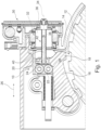
- Figure 1 shows a cross-section through a parking lock 10, which does not fall under the wording of claim 8.
- the parking lock 10 is designed in a vehicle for Limitation of a rotary movement of a locking ring 12, for example in a transmission.
- the locking ring 12 has a locking toothing 14 on its outer circumference.
- the parking lock 10 comprises a pawl 16, which can be positively connected to the locking ring 12 with a pawl tooth 18 and thereby limits or prevents a rotary movement of the locking ring 12.
- the pawl 16 is rotatable and pre-tensioned by a tension spring. If the parking lock 10 is in a release position, the pawl tooth 18 is located outside the locking teeth 14. In a locking position, the pawl tooth 18 engages in the locking teeth 14 in a form-fitting manner. The pawl tooth 18 moves towards or away from the locking ring 12 with a rotation of the pawl 16.
- the parking lock 10 is actuated by an actuating slide 20, which has a first roller 22 and a second roller 24 and can be moved translationally in an axial direction 26.
- the actuating slide 20 In the release position, the actuating slide 20 is in a left position and in the locking position in a right position.
- a ramp 28 on the pawl 16 aligns the latter in the left position by the tensioning force of the tension spring away from the locking ring 12. If the actuating slide 20 is moved to the right to initiate a locking position, the first roller 22 rolls on the ramp 28 and rotates the pawl 16, whereby the pawl tooth 18 is brought into engagement with the locking teeth 14 of the locking ring 12 and the parking lock assumes a locking position.
- the axial displacement of the actuating carriage 20 is effected by an actuator 30, which comprises an electric motor 32.
- the electric motor 32 has a rotor 36 that can rotate about an axis of rotation 34 and which is assigned a thread 38 for positive connection to an actuating element 40 that can be moved translationally in the axial direction 26.
- the actuating element 40 is designed as a spindle shaft and the thread 38 as a spindle nut, which together form a spindle drive 42 that converts a rotary movement of the rotor 36 into a translational movement of the actuating element 40 and thus effects a mechanical translation.
- the actuating element 40 is connected to the actuating slide 20 and a movement of the actuating element 40 leads to a corresponding movement of the actuating slide 20, which in turn deflects the pawl 16.
- the rotational movement of the rotor 36 is converted into the axial movement of the actuating element 40 within the electric motor 32, which means that installation space can be saved for a mechanical transmission arranged separately from the electric motor 32.
- the installation space can be further reduced and the manufacturing costs and assembly effort can be reduced by making the thread 38 a single piece from the rotor 36.
- a spindle nut provided separately from the rotor 36 to effect the mechanical transmission can thus be dispensed with.
- the number of parts required to implement the mechanical transmission can be reduced.
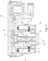
- FIG 2 is a cross-section through an actuator 30, which does not fall under the wording of claim 7.
- the actuator 30 comprises an electric motor 32 designed as a brushless direct current motor (BLDC), which has a stator 44 and a rotor 36 that can rotate about an axis of rotation 34.
- a stator 44 arranged radially outside the rotor 36 has grooves distributed around the circumference, in which a wire winding 37 for commutation of the electric motor 32 is arranged.
- the stator 44 is preferably designed as a laminated core and is firmly connected to an actuator housing 46, which accommodates control electronics 48 with which the electric motor 32 can be controlled.
- the rotor 36 has a first outer circumference 50.
- a plurality of magnetic field elements 54 are each arranged distributed around the circumference for generating a magnetic field to cause a rotary movement of the rotor 36 about the axis of rotation 34.
- the magnetic field elements 54 are each sintered permanent magnets which are attached to the first outer circumference 50 in an SPM (Surface Permanent Magnet) arrangement.
- the magnetic field elements 54 can be glued to the rotor 36.
- the electric motor 32 is an internal rotor motor in which the rotor 36 is arranged radially inside the stator 44.
- the rotor 36 is a sintered part which is made from fine-grained ceramic or metallic material sintered using pressure and heating up to a predetermined production temperature.
- the production temperature is preferably below the melting temperature of the material or at least one of the materials forming the sintered part. Materials. This allows the shape of the rotor 36 to be retained and the mechanical load capacity to be increased.
- the material from which the rotor 36 is made is preferably ferromagnetic in order to increase the efficiency of the electric motor 32.
- the rotor 36 has a recess 58 arranged radially inside, concentric to the axis of rotation 34, for example a central bore, which defines an inner circumference 60 of the rotor 36.
- a thread 38 here an internal thread
- the actuating element 40 has an external thread 62 corresponding to the thread 38 and a rotary movement of the rotor 36 is converted by this mechanical translation into a translational movement of the actuating element 40, for example for actuating a parking lock.
- the actuating element 40 is designed here as a spindle shaft of a spindle drive 42.
- the rotor 36 has a bearing receiving area 66, which is designed as a single piece with the rotor 36 on a second outer circumference 64 of the rotor 36 that is different from the first outer circumference 50, for receiving a bearing 68.
- the bearing 68 is designed as a rolling bearing and can be connected to the rotor 36 in a form-fitting manner by a rolling process.
- the bearing 68 can be secured by the rolling process via a deformation 70 of the rotor 36.
- the rotor 36 further comprises a sensor receiving area 72 which is designed in one piece with the rotor 36 for receiving a sensor component 74 of a sensor 76.
- the sensor 76 is a rotary sensor for detecting a rotary position of the rotor 26 and the sensor component 74 is a round sensor magnet which is attached to the rotor 36 concentrically to the axis of rotation 34 and is directly connected to the rotor 36.
- the rotor 36 is designed to save particularly much space, as a bearing receiving area 66, a sensor receiving area 72 and a spindle nut are designed as one piece with it. This also reduces the assembly effort required to manufacture the electric motor 32.
- Figure 3 shows a cross-section through a rotor which does not fall under the wording of claim 1.
- a plurality of magnetic field elements 54 distributed around the circumference are attached to a first outer circumference 50 of the rotor 36.
- the magnetic field elements 54 are glued to the first outer circumference 50 in an SPM arrangement.
- a bearing receiving area 66 is formed in one piece with the rotor 36, on which a bearing (not shown here) can be received and firmly connected to the rotor.
- a sensor receiving area 72 is designed as one piece with the rotor 36.
- a sensor component 74 of a sensor 76 for detecting a rotational position of the rotor 36 is accommodated therein concentrically to the rotational axis 34.
- the sensor component 74 can be a sensor magnet that is pressed into the rotor 36.
- the rotor 36 is a sintered part and a thread 38 is formed in one piece with the rotor 36 in a recess 58 arranged radially on the inside of the rotor 36.
- the thread 38 is an internal thread.
- An actuating element 40 with a corresponding external thread 62 is received in a form-fitting manner in the internal thread. This allows a rotary movement of the rotor 36 to be translated into an axial movement of the actuating element 40.
- Figure 4 a spatial view of a rotor which does not fall under the wording of claim 1 is shown.
- Figure 5 shows another spatial view of the rotor in Figure 4
- the rotor 36 has magnetic field elements 54 distributed around the circumference on a first outer circumference 50.
- the magnetic field elements 54 can be permanent magnets attached to the rotor 36 in an SPM arrangement.
- the rotor 36 has a bearing receiving area 66 for receiving a bearing, for example a rolling bearing, on a second outer circumference 64, which is in particular smaller than the first outer circumference 50.
- FIG 6 is a cross-section through an electric motor 32 in a special embodiment of the invention.
- a stator 44 arranged radially outside the rotor 36 has grooves distributed around the circumference in which a wire winding 37 is arranged for commutation of the electric motor 32.
- the stator 44 is designed as a laminated core.
- the rotor 36 of the electric motor 32 is designed as a formed part, in particular as a deep-drawn part, and comprises a radially outer first bending section 78 which defines the first outer circumference 50 and a radially inner second bending section 80.
- the first and second bending sections 78, 80 are connected to one another in one piece on a first axial side 82 of the rotor 36.
- the thread 38 for connection to an actuating element 40 is designed in one piece from the second bending section 80.
- the second bending section 80 defines an inner circumference 60 of the rotor 36, the thread 38 being designed as an internal thread on the inner circumference 60.
- the first bending section 78 defines the first outer circumference 50 of the rotor, to which the magnetic field elements 54 distributed around the circumference are firmly connected.
- a bearing receiving area 66 for receiving a bearing 68 is made in one piece from the rotor 36.
- the second outer circumference 64 is larger than the first outer circumference 50.
Landscapes
- Engineering & Computer Science (AREA)
- General Engineering & Computer Science (AREA)
- Mechanical Engineering (AREA)
- Power Engineering (AREA)
- Connection Of Motors, Electrical Generators, Mechanical Devices, And The Like (AREA)
- Lock And Its Accessories (AREA)
Description
- Die Erfindung betrifft einen Rotor für einen Elektromotor nach dem Oberbegriff von Anspruch 1. Weiterhin betrifft die Erfindung einen Elektromotor mit einem derartigen Rotor, einen Aktor mit einem derartigen Elektromotor und eine Parksperre mit einem derartigen Aktor.
- Es ist bekannt einen Rotor für einen Elektromotor beispielsweise in einer Parksperre für ein Automatikgetriebe in einem Kraftfahrzeug einzusetzen. In
DE 10 2017 102 804 A1 wird eine Parksperre beschrieben, bei der ein Elektromotor eine Spindel antreibt, mit der sich eine Spindelmutter in Eingriff befindet. Die Spindelmutter ist drehfest in einer Führungsnut geführt. Wird der Elektromotor in Drehung versetzt, wird die Spindelmutter bewegt und dadurch die Parksperre betätigt. - Um Bauraum einzusparen ist es bekannt, die mechanische Übersetzung, die eine Drehbewegung in eine translatorische Bewegung umsetzt, in den Elektromotor zu integrieren. Üblicherweise wird in den Rotor des Elektromotors eine Spindelmutter eingepresst, die mit einer Spindelwelle formschlüssig verbunden wird. Eine Drehbewegung der mit dem Rotor drehbaren Spindelmutter wird damit in eine translatorische Bewegung der Spindelwelle umgewandelt, die beispielsweise eine Betätigung einer Parksperre bewirkt.
- Die
EP2873891A1 offenbart in seinerFig.4 einen Rotor für einen Elektromotor gemäß dem Oberbegriff des Anspruchs 1. - Die Aufgabe der vorliegenden Erfindung besteht darin, einen Rotor in einem Elektromotor zu verbessern. Der Bauraum, Montageaufwand und die Herstellungskosten eines Rotors sollen verringert werden.
- Wenigstens eine dieser Aufgaben wird durch einen Rotor für einen Elektromotor mit den Merkmalen nach Anspruch 1 gelöst. Entsprechend wird ein Rotor für einen Elektromotor vorgeschlagen, wobei der Rotor um eine Drehachse drehbar ist und einen ersten Außenumfang und ein im Bereich des ersten Außenumfangs angeordnetes Magnetfeldelement zur Erzeugung eines Magnetfelds zur Bewirkung einer Drehbewegung des Rotors aufweist, wobei dem Rotor ein Gewinde zur formschlüssigen Verbindung mit einem translatorisch bewegbaren Betätigungselement zugeordnet ist, wobei das Gewinde einteilig aus dem Rotor ausgeführt ist.
- Dadurch kann der Rotor einfacher aufgebaut und eingebaut werden. Die Herstellungskosten und der Montageaufwand werden verringert. Der Rotor kann kleinere Abmessungen aufweisen. Der Bauraumbedarf und die Bauteileanzahl können verringert werden.
- Das Magnetfeldelement kann ein Permanentmagnet oder eine Drahtspule sein. Der Permanentmagnet kann gesintert sein. Der Permanentmagnet kann innerhalb des Rotors in IPM (Interior Permanent Magnet) Anordnung oder auf dem Außenumfang in SPM (Surface Permanent Magnet) Anordnung mit dem Rotor befestigt sein. Das Magnetfeldelement kann mit dem Rotor fest verbunden sein, beispielsweise formschlüssig, kraftschlüssig oder stoffschlüssig mit dem Rotor verbunden sein. Das Magnetfeldelement kann mit dem Rotor verklebt sein.
- Es können wenigstens zwei umfangsseitig verteilt angeordnete Magnetfeldelemente im Bereich des Außenumfangs angeordnet sein.
- Das Gewinde kann eine Spindelmutter bilden, die mit dem als Spindelwelle ausgeführten translatorisch bewegbaren Betätigungselement formschlüssig verbunden werden kann. Das Gewinde kann als Innengewinde ausgeführt sein. Der Rotor kann aus einem ferromagnetischen Material bestehen.
- In einer bevorzugten Ausführung der Erfindung weist der Rotor radial innen eine Aussparung auf, die einen Innenumfang des Rotors festlegt, wobei das Gewinde an dem Innenumfang ausgeführt ist. Die Aussparung kann konzentrisch zu der Drehachse sein. Die Aussparung kann eine Zentralbohrung sein.
- Erfindungsgemäß ist der Rotor als Umformteil ausgeführt, aufweisend einen radial äußeren und den ersten Außenumfang festlegenden ersten Biegeabschnitt und einen radial inneren zweiten Biegeabschnitt, wobei der erste und zweite Biegeabschnitt auf einer ersten axialen Seite des Rotors einteilig miteinander verbunden sind und das Gewinde einteilig aus dem zweiten Biegeabschnitt ausgeführt ist. Das Umformteil kann ein Blechbauteil sein. Das Umformteil kann ein Tiefziehteil sein. Der zweite Biegeabschnitt kann einen Innenumfang des Rotors festlegen, wobei das Gewinde an dem Innenumfang ausgeführt ist. Der erste Biegeabschnitt kann den ersten Außenumfang des Rotors festlegen. Das Magnetfeldelement kann mit dem ersten Biegeabschnitt fest verbunden sein.
- In einer vorteilhaften Ausführung der Erfindung weist der Rotor einen einteilig mit diesem ausgeführten Lageraufnahmebereich zur Aufnahme eines Lagers auf. Das Lager kann ein Wälzlager sein.
- In einer speziellen Ausgestaltung der Erfindung ist der Lageraufnahmebereich an einem von dem ersten Außenumfang verschiedenen zweiten Außenumfang des Rotors angeordnet ist. Der zweite Außenumfang kann kleiner oder grösser als der erste Außenumfang sein. Das Lager durch ein Rollierverfahren mit dem Rotor verbunden werden. Das Lager kann formschlüssig mit dem Rotor verbunden sein. Durch das Rollierverfahren kann das Lager durch eine Umformung des Rotors gesichert sein.
- In einer bevorzugten Ausführung der Erfindung weist der Rotor einen einteilig mit diesem ausgeführten Sensoraufnahmebereich zur Aufnahme eines Sensorbauteils eines Sensors auf. Der Sensor kann ein Drehsensor sein. Das Sensorbauteil kann ein Sensormagnet sein. Der Sensor kann zur Erfassung einer Drehlage des Rotors wirksam sein. Das Sensorbauteil kann unmittelbar mit dem Rotor verbunden sein. Das Sensorbauteil kann rund sein. Das Sensorbauteil kann konzentrisch mit der Drehachse an dem Rotor befestigt sein. Der Sensoraufnahmebereich kann an einer ersten Seite des Rotors angeordnet sein. Der Sensoraufnahmebereich kann konzentrisch zu der Drehachse sein. Das Sensorbauteil kann in dem Sensoraufnahmebereich eingepresst sein.
- Zur Lösung wenigstens einer der zuvor genannten Aufgaben wird weiterhin ein Elektromotor mit einem Stator und einem Rotor mit wenigstens einem der vorstehenden Merkmale vorgeschlagen. Der Elektromotor kann ein bürstenloser Gleichstrommotor (BLDC) sein. Der Rotor kann radial innerhalb des Stators drehbar angeordnet sein. Der Elektromotor kann ein Innenläufermotor sein.
- Zur Lösung wenigstens einer der zuvor genannten Aufgaben wird weiterhin ein Aktor mit einem Spindeltrieb und einem zuvor beschriebenen Elektromotor vorgeschlagen, wobei das Betätigungselement als Spindelwelle ausgeführt ist und das Gewinde eine Spindelmutter bildet, die mit der Spindelwelle formschlüssig verbindbar ist.
- Zur Lösung wenigstens einer der zuvor genannten Aufgaben wird weiterhin eine Parksperre in einem Fahrzeug mit einem zuvor beschriebenen Aktor vorgeschlagen, wobei das Betätigungselement mit einer Sperrklinke wirksam verbunden ist und durch die translatorische Bewegung eine Freigabestellung oder eine Sperrstellung bewirken kann. Die Parksperre kann eine Drehbewegung eines Drehbauteils, beispielsweise eines Rastrings, begrenzen oder verhindern. Das Drehbauteil kann in einem Getriebe des Fahrzeugs angeordnet sein.
- Weitere Vorteile und vorteilhafte Ausgestaltungen der Erfindung ergeben sich aus der Figurenbeschreibung und den Abbildungen.
- Die Erfindung wird im Folgenden unter Bezugnahme auf die Abbildungen ausführlich beschrieben, wobei nur die
Fig.6 einen erfindungsgemäßen Rotor zeigt, also einen Rotor, der unter den Wortlaut des Anspruchs 1 fällt. - Es zeigen im Einzelnen:
-
Figur 1 : Einen Querschnitt durch eine Parksperre, die nicht unter den Wortlaut des Anspruchs 8 fällt. -
Figur 2 : Einen Querschnitt durch einen Aktor, der nicht unter den Wortlaut des Anspruchs 7 fällt. -
Figur 3 : Einen Querschnitt durch einen Rotor, der nicht unter den Wortlaut des Anspruchs 1 fällt. -
Figur 4 : Eine räumliche Ansicht eines Rotors, der nicht unter den Wortlaut des Anspruchs 1 fällt. -
Figur 5 : Eine andere räumliche Ansicht des Rotors inFigur 4 . -
Figur 6 : Einen Querschnitt durch einen Elektromotor in einer speziellen Ausführungsform der Erfindung. -
Figur 1 zeigt einen Querschnitt durch eine Parksperre 10, die nicht unter den Wortlaut des Anspruchs 8 fällt. - Die Parksperre 10 ist in einem Fahrzeug zur Beschränkung einer Drehbewegung eines Rastrings 12, beispielsweise in einem Getriebe, eingebaut. Der Rastring 12 weist an seinem Außenumfang eine Rastverzahnung 14 auf. Die Parksperre 10 umfasst eine Sperrklinke 16, die mit einem Klinkenzahn 18 formschlüssig mit dem Rastring 12 verbunden werden kann und dabei eine Drehbewegung des Rastrings 12 beschränkt oder verhindert.
- Die Sperrklinke 16 ist drehbar und durch eine Spannfeder vorgespannt. Ist die Parksperre 10 in einer Freigabestellung, dann liegt der Klinkenzahn 18 außerhalb der Rastverzahnung 14. In einer Sperrstellung greift der Klinkenzahn 18 in die Rastverzahnung 14 formschlüssig ein. Der Klinkenzahn 18 bewegt sich mit einer Drehung der Sperrklinke 16 hin zu oder weg von dem Rastring 12.
- Die Betätigung der Parksperre 10 erfolgt durch einen Betätigungsschlitten 20, der eine erste Rolle 22 und eine zweite Rolle 24 aufweist und in eine axiale Richtung 26 translatorisch verschiebbar ist. In der Freigabestellung ist der Betätigungsschlitten 20 in einer linken Position und bei der Sperrstellung in einer rechten Position. Durch eine Rampe 28 an der Sperrklinke 16 ist diese in der linken Position durch die Spannkraft der Spannfeder weg von dem Rastring 12 ausgerichtet. Wird der Betätigungsschlitten 20 zur Einleitung einer Sperrstellung nach rechts bewegt, dann rollt die erste Rolle 22 auf der Rampe 28 ab und dreht die Sperrklinke 16, womit der Klinkenzahn 18 in Eingriff mit der Rastverzahnung 14 des Rastrings 12 gebracht wird und die Parksperre eine Sperrstellung einnimmt.
- Die axiale Verschiebung des Betätigungsschlittens 20 wird durch einen Aktor 30 bewirkt, der einen Elektromotor 32 umfasst. Der Elektromotor 32 weist einen um eine Drehachse 34 drehbaren Rotor 36 auf, dem ein Gewinde 38 zur formschlüssigen Verbindung mit einem in die axiale Richtung 26 translatorisch bewegbaren Betätigungselement 40 zugeordnet ist. Das Betätigungselement 40 ist als Spindelwelle und das Gewinde 38 als Spindelmutter ausgeführt, die zusammen einen Spindeltrieb 42 bilden, der eine Drehbewegung des Rotors 36 in eine translatorische Bewegung des Betätigungselements 40 umwandelt und damit eine mechanische Übersetzung bewirkt.
- Das Betätigungselement 40 ist mit dem Betätigungsschlitten 20 verbunden und eine Bewegung des Betätigungselements 40 führt zu einer entsprechenden Bewegung des Betätigungsschlittens 20, der wiederum die Sperrklinke 16 auslenkt. Die Übersetzung der Drehbewegung des Rotors 36 in die axiale Bewegung des Betätigungselements 40 ist innerhalb des Elektromotors 32 verwirklicht, wodurch bereits Bauraum für eine getrennt von dem Elektromotor 32 angeordnete mechanische Übersetzung eingespart werden kann.
- Der Bauraum kann weiter verringert werden und die Herstellungskosten und der Montageaufwand können gesenkt werden, indem das Gewinde 38 einteilig aus dem Rotor 36 ausgeführt ist. Eine getrennt von dem Rotor 36 vorgesehene Spindelmutter zur Bewirkung der mechanischen Übersetzung kann damit entbehrlich sein. Die Anzahl der benötigten Teile für die Umsetzung der mechanischen Übersetzung kann verringert werden.
- In
Figur 2 ist ein Querschnitt durch einen Aktor 30, der nicht unter den Wortlaut des Anspruchs 7 fällt. Der Aktor 30 umfasst einen als bürstenloser Gleichstrommotor (BLDC) ausgeführten Elektromotor 32, der einen Stator 44 und einen um eine Drehachse 34 drehbaren Rotor 36 aufweist. Ein radial außerhalb des Rotors 36 angeordneter Stator 44 weist umfangsseitig verteilt angeordnete Nuten auf, in denen eine Drahtwicklung 37 zur Kommutierung des Elektromotors 32 angeordnet ist. Der Stator 44 ist vorzugsweise als Blechpaket ausgeführt und mit einem Aktorgehäuse 46 fest verbunden, das eine Steuerelektronik 48 aufnimmt, mit der der Elektromotor 32 gesteuert werden kann. Der Rotor 36 weist einen ersten Außenumfang 50 auf. In dem Bereich 52 des ersten Außenumfangs 50 sind mehrere Magnetfeldelemente 54 jeweils zur Erzeugung eines Magnetfelds zur Bewirkung einer Drehbewegung des Rotors 36 um die Drehachse 34 umfangsseitig verteilt angeordnet. Die Magnetfeldelemente 54 sind jeweils gesinterte Permanentmagnete, die auf dem ersten Außenumfang 50 in SPM (Surface Permanent Magnet) Anordnung befestigt sind. Die Magnetfeldelemente 54 können mit dem Rotor 36 verklebt sein. - Der Elektromotor 32 ist ein Innenläufermotor, bei dem der Rotor 36 radial innerhalb von dem Stator 44 angeordnet ist. Der Rotor 36 ist ein Sinterteil, das aus unter Anwendung eines Drucks und einer Erwärmung bis zu einer vorgegebenen Herstellungstemperatur gesintertem feinkörnigen keramischen oder metallischen Stoff hergestellt ist. Die Herstellungstemperatur ist vorzugsweise unterhalb der Schmelztemperatur des Stoffs oder zumindest eines der das Sinterteil bildenden Stoffe. Dadurch kann die Form des Rotors 36 erhalten bleiben und die mechanische Belastbarkeit kann vergrößert werden. Das Material, aus dem der Rotor 36 besteht, ist bevorzugt ferromagnetisch um den Wirkungsgrad des Elektromotors 32 zu steigern.
- Der Rotor 36 weist radial innen eine konzentrische zu der Drehachse 34 angeordnete Aussparung 58, beispielsweise eine Zentralbohrung auf, die einen Innenumfang 60 des Rotors 36 festlegt. An dem Innenumfang 60 ist eine Gewinde 38, hier ein Innengewinde, einteilig aus dem Rotor 36 ausgeführt, das mit einem Betätigungselement 40 formschlüssig verbunden ist. Das Betätigungselement 40 weist ein dem Gewinde 38 entsprechendes Außengewinde 62 auf und eine Drehbewegung des Rotors 36 wird durch diese mechanische Übersetzung in eine translatorische Bewegung des Betätigungselement 40, beispielsweise zur Betätigung einer Parksperre, umgesetzt. Das Betätigungselement 40 ist hier als Spindelwelle eines Spindeltriebs 42 ausgeführt.
- Der Rotor 36 weist an einem von dem ersten Außenumfang 50 verschiedenen zweiten Außenumfang 64 des Rotors 36 einen einteilig mit diesem ausgeführten Lageraufnahmebereich 66 zur Aufnahme eines Lagers 68 auf. Das Lager 68 ist als Wälzlager ausgeführt und kann durch ein Rollierverfahren formschlüssig mit dem Rotor 36 verbunden werden. Beispielsweise kann das Lager 68 durch das Rollierverfahren über eine Umformung 70 des Rotors 36 gesichert sein.
- Der Rotor 36 umfasst weiterhin einen einteilig mit diesem ausgeführten Sensoraufnahmebereich 72 zur Aufnahme eines Sensorbauteils 74 eines Sensors 76 auf. Der Sensor 76 ist ein Drehsensor zur Erfassung einer Drehlage des Rotors 26 und das Sensorbauteil 74 ist ein runder und konzentrisch zu der Drehachse 34 mit dem Rotor 36 befestigter Sensormagnet, der unmittelbar mit dem Rotor 36 verbunden ist.
- Der Rotor 36 ist besonders bauraumsparend ausgeführt, indem einteilig mit diesem ein Lageraufnahmebereich 66, ein Sensoraufnahmebereich 72 und eine Spindelmutter ausgeführt ist. Dadurch kann auch der Montageaufwand zur Herstellung des Elektromotors 32 gesenkt werden.
-
Figur 3 zeigt einen Querschnitt durch einen Rotor, der nicht unter den Wortlaut des Anspruchs 1 fällt. - An einem ersten Außenumfang 50 des Rotors 36 sind mehrere umfangsseitig verteilt angeordnete Magnetfeldelemente 54 befestigt. Die Magnetfeldelemente 54 sind in SPM Anordnung mit dem ersten Außenumfang 50 verklebt. An einem zweiten Außenumfang 64, der bevorzugt kleiner als der erste Außenumfang 50 ist, ist ein Lageraufnahmebereich 66 einteilig mit dem Rotor 36 ausgeführt, an dem ein hier nicht dargestelltes Lager aufnehmbar und fest mit dem Rotor verbindbar ist.
- Weiterhin ist ein Sensoraufnahmebereich 72 einteilig mit dem Rotor 36 ausgeführt. Darin ist ein Sensorbauteil 74 eines Sensors 76 zur Erkennung einer Drehlage des Rotors 36 konzentrisch zu der Drehachse 34 aufgenommen. Das Sensorbauteil 74 kann ein Sensormagnet sein, der in dem Rotor 36 eingepresst ist.
- Der Rotor 36 ist ein Sinterteil und in einer radial innen an dem Rotor 36 angeordneten Aussparung 58 ist ein Gewinde 38 einteilig mit dem Rotor 36 ausgeführt. Das Gewinde 38 ist ein Innengewinde. In dem Innengewinde ist ein Betätigungselement 40 mit einem entsprechenden Außengewinde 62 formschlüssig aufgenommen. Dadurch kann eine Drehbewegung des Rotors 36 in eine axiale Bewegung des Betätigungselements 40 übersetzt werden.
- In
Figur 4 ist eine räumliche Ansicht eines Rotors, der nicht unter den Wortlaut des Anspruchs 1 fällt, dargestellt.Figur 5 zeigt eine andere räumliche Ansicht des Rotors inFigur 4 . Der Rotor 36 weist an einem ersten Außenumfang 50 umfangsseitig verteilt angeordnete Magnetfeldelemente 54 auf. Die Magnetfeldelemente 54 können in SPM Anordnung an dem Rotor 36 befestigte Permanentmagnete sein. - Der Rotor 36 weist an einem zweiten Außenumfang 64, der insbesondere kleiner als der erste Außenumfang 50 ist, einen Lageraufnahmebereich 66 zur Aufnahme eines Lagers, beispielsweise eines Wälzlagers, auf.
- In
Figur 6 ist ein Querschnitt durch einen Elektromotor 32 in einer speziellen Ausführungsform der Erfindung dargestellt. Ein radial außerhalb des Rotors 36 angeordneter Stator 44 weist umfangsseitig verteilt angeordnete Nuten auf, in denen eine Drahtwicklung 37 zur Kommutierung des Elektromotors 32 angeordnet ist. Der Stator 44 ist als Blechpaket ausgeführt. - Der Rotor 36 des Elektromotors 32 ist als Umformteil, insbesondere als Tiefziehteil, ausgeführt und umfasst einen radial äußeren und den ersten Außenumfang 50 festlegenden ersten Biegeabschnitt 78 und einen radial inneren zweiten Biegeabschnitt 80. Der erste und zweite Biegeabschnitt 78, 80 sind auf einer ersten axialen Seite 82 des Rotors 36 einteilig miteinander verbunden. Das Gewinde 38 zur Verbindung mit einem Betätigungselement 40 ist einteilig aus dem zweiten Biegeabschnitt 80 ausgeführt. Der zweite Biegeabschnitt 80 legt dabei einen Innenumfang 60 des Rotors 36 fest, wobei das Gewinde 38 als Innengewinde an dem Innenumfang 60 ausgeführt ist.
- Der erste Biegeabschnitt 78 legt den ersten Außenumfang 50 des Rotors fest, an dem die umfangsseitig verteilt angeordneten Magnetfeldelemente 54 fest verbunden sind. An einem zweiten Außenumfang 64 des Rotors 36, hier an dem ersten Biegeabschnitt 78, ist ein Lageraufnahmebereich 66 zur Aufnahme eines Lagers 68 einteilig aus dem Rotor 36 ausgeführt. Der zweite Außenumfang 64 ist dabei grösser als der erste Außenumfang 50.
-
- 10
- Parksperre
- 12
- Rastring
- 14
- Rastverzahnung
- 16
- Sperrklinke
- 18
- Klinkenzahn
- 20
- Betätigungsschlitten
- 22
- erste Rolle
- 24
- zweite Rolle
- 26
- axiale Richtung
- 28
- Rampe
- 30
- Aktor
- 32
- Elektromotor
- 34
- Drehachse
- 36
- Rotor
- 37
- Drahtwicklung
- 38
- Gewinde
- 40
- Betätigungselement
- 42
- Spindeltrieb
- 44
- Stator
- 46
- Aktorgehäuse
- 48
- Steuerelektronik
- 50
- erster Außenumfang
- 52
- Bereich
- 54
- Magnetfeldelement
- 58
- Aussparung
- 60
- Innenumfang
- 62
- Außengewinde
- 64
- zweiter Außenumfang
- 66
- Lageraufnahmebereich
- 68
- Lager
- 70
- Umformung
- 72
- Sensoraufnahmebereich
- 74
- Sensorbauteil
- 76
- Sensor
- 78
- erster Biegeabschnitt
- 80
- zweiter Biegeabschnitt
- 82
- axiale Seite
Claims (8)
- Rotor (36) für einen Elektromotor (32), wobeider Rotor (36) um eine Drehachse (34) drehbar ist und einen ersten Außenumfang (50) und ein im Bereich des ersten Außenumfangs (50) angeordnetes Magnetfeldelement (54) zur Erzeugung eines Magnetfelds zur Bewirkung einer Drehbewegung des Rotors (36) aufweist, unddem Rotor (36) ein Gewinde (38) zur formschlüssigen Verbindung mit einem translatorisch bewegbaren Betätigungselement (40) zugeordnet ist,wobei das Gewinde (38) einteilig aus dem Rotor (36) ausgeführt ist, dadurch gekennzeichnet, dassder Rotor (36) als Umformteil ausgeführt ist, aufweisend einen radial äußeren und den ersten Außenumfang (50) festlegenden ersten Biegeabschnitt (78) und einen radial inneren zweiten Biegeabschnitt (80), undder erste und zweite Biegeabschnitt (78, 80) auf einer ersten axialen Seite (82) des Rotors einteilig miteinander verbunden sind und das Gewinde (38) einteilig aus dem zweiten Biegeabschnitt (80) ausgeführt ist.
- Rotor (36) nach Anspruch 1, dadurch gekennzeichnet, dassder Rotor (36) eine radial innen angeordnete Aussparung (58) aufweist, die einen Innenumfang (60) des Rotors (36) festlegt, unddas Gewinde (38) an dem Innenumfang (60) ausgeführt ist.
- Rotor (36) nach einem der vorangehenden Ansprüche, dadurch gekennzeichnet, dass der Rotor (36) einen einteilig mit diesem ausgeführten Lageraufnahmebereich (66) zur Aufnahme eines Lagers (68) aufweist.
- Rotor (36) nach Anspruch 3, dadurch gekennzeichnet, dass der Lageraufnahmebereich (66) an einem von dem ersten Außenumfang (50) verschiedenen zweiten Außenumfang (64) des Rotors (36) angeordnet ist.
- Rotor (36) nach einem der vorangehenden Ansprüche, dadurch gekennzeichnet, dass der Rotor (36) einen einteilig mit diesem ausgeführten Sensoraufnahmebereich (72) zur Aufnahme eines Sensorbauteils (74) eines Sensors (76) aufweist.
- Elektromotor (32) mit einem Stator (44) und einem Rotor (36) nach einem der vorangehenden Ansprüche.
- Aktor (30) mit einem Spindeltrieb (42) und einem Elektromotor (32) nach Anspruch 6, wobei das Betätigungselement (40) als Spindelwelle ausgeführt ist und das Gewinde (38) eine Spindelmutter bildet, die mit der Spindelwelle formschlüssig verbindbar ist.
- Parksperre (10) in einem Fahrzeug mit einem Aktor (30) nach Anspruch 7, wobei das Betätigungselement (40) mit einer Sperrklinke (16) wirksam verbunden ist und durch die Sperrklinke (16) bei einer translatorischen Bewegung des Betätigungselements (40) eine Freigabestellung oder eine Sperrstellung bewirkbar ist.
Applications Claiming Priority (2)
| Application Number | Priority Date | Filing Date | Title |
|---|---|---|---|
| DE102018131607.0A DE102018131607A1 (de) | 2018-12-10 | 2018-12-10 | Rotor mit einteiligem Gewinde, sowie Elektromotor, Aktor und Parksperre |
| PCT/DE2019/101013 WO2020119853A2 (de) | 2018-12-10 | 2019-11-26 | Rotor mit einteiligem gewinde, sowie elektromotor, aktor und parksperre |
Publications (2)
| Publication Number | Publication Date |
|---|---|
| EP3894726A2 EP3894726A2 (de) | 2021-10-20 |
| EP3894726B1 true EP3894726B1 (de) | 2025-02-26 |
Family
ID=68886675
Family Applications (1)
| Application Number | Title | Priority Date | Filing Date |
|---|---|---|---|
| EP19820666.6A Active EP3894726B1 (de) | 2018-12-10 | 2019-11-26 | Rotor mit einteiligem gewinde, sowie elektromotor, aktor und parksperre |
Country Status (3)
| Country | Link |
|---|---|
| EP (1) | EP3894726B1 (de) |
| DE (1) | DE102018131607A1 (de) |
| WO (1) | WO2020119853A2 (de) |
Families Citing this family (4)
| Publication number | Priority date | Publication date | Assignee | Title |
|---|---|---|---|---|
| CN115059758B (zh) * | 2022-06-27 | 2023-10-13 | 江西福格新能源传动技术有限公司 | 一种新能源汽车变速箱用传动轴锁定设备及其实施方法 |
| US12247658B2 (en) * | 2022-09-28 | 2025-03-11 | Allison Transmission, Inc. | Electric park systems, transmissions incorporating the same, and methods for transmissions |
| FR3145025B1 (fr) * | 2023-01-18 | 2025-03-14 | Valeo Embrayages | Actionneur pour un système de verrouillage en stationnement d’une boîte de transmission de véhicule |
| DE102024124272A1 (de) | 2024-08-26 | 2026-02-26 | Bayerische Motoren Werke Aktiengesellschaft | Formschlusskupplung, Parksperreinheit, Getriebe-Abkoppeleinheit und Kraftfahrzeug |
Family Cites Families (4)
| Publication number | Priority date | Publication date | Assignee | Title |
|---|---|---|---|---|
| CN103378707B (zh) * | 2012-04-23 | 2017-12-19 | 德昌电机(深圳)有限公司 | 电机、线性驱动器、及使用该线性驱动器的车灯调节器 |
| US20150171702A1 (en) * | 2012-07-10 | 2015-06-18 | Nsk Ltd. | Electric actuator |
| DE102013213706A1 (de) * | 2013-07-12 | 2015-01-15 | Schaeffler Technologies Gmbh & Co. Kg | Parksperre |
| DE102017102804B4 (de) | 2017-02-13 | 2019-03-14 | Schaeffler Technologies AG & Co. KG | Vorrichtung zum Betätigen einer Parksperre |
-
2018
- 2018-12-10 DE DE102018131607.0A patent/DE102018131607A1/de not_active Withdrawn
-
2019
- 2019-11-26 WO PCT/DE2019/101013 patent/WO2020119853A2/de not_active Ceased
- 2019-11-26 EP EP19820666.6A patent/EP3894726B1/de active Active
Also Published As
| Publication number | Publication date |
|---|---|
| DE102018131607A1 (de) | 2020-06-10 |
| WO2020119853A2 (de) | 2020-06-18 |
| WO2020119853A3 (de) | 2020-08-27 |
| EP3894726A2 (de) | 2021-10-20 |
Similar Documents
| Publication | Publication Date | Title |
|---|---|---|
| WO2020119853A2 (de) | Rotor mit einteiligem gewinde, sowie elektromotor, aktor und parksperre | |
| DE102019110384A1 (de) | Parksperrenanordnung | |
| EP2297839A2 (de) | Getriebe-antriebseinheit mit einer selbsthemmvorrichtung | |
| WO2019122074A1 (de) | Rotor für einen elektromotor und elektromotor | |
| WO2021121855A1 (de) | Aktuatorvorrichtung zur erzeugung einer longitudinalen stellbewegung | |
| DE102017102630A1 (de) | Linearschrittmotor, sowie Vorrichtung und Verfahren zur Herstellung eines Linearschrittmotors mit kugelgelagerter Rotorwelle | |
| EP2617123B1 (de) | Elektromotor | |
| DE102019127901A1 (de) | Elektromechanische Scheibenbremse mit einem Parkbremsaktuator für Kraftfahrzeuge | |
| DE102010018000A1 (de) | Drehmomenteinstellvorrichtung | |
| EP2097964B1 (de) | Drehfeldmaschine mit glockenläufer | |
| EP1320176B1 (de) | Betätigungsvorrichtung, insbesondere zur Betätigung von Sperrdifferentialen von Fahrzeugen | |
| EP2436913B1 (de) | Starter für eine Brennkraftmaschine | |
| DE102008025512A1 (de) | Verfahren zum Zusammenbau des Stators einer elektrischen Maschine sowie elektrische Maschine | |
| DE102004058096A1 (de) | Sperrvorrichtung, sowie Getriebe-Antriebseinheit beinhaltend eine solche Sperrvorrichtung, sowie Verfahren zum Herstellen einer solchen Getriebe-Antriebseinheit | |
| DE3922794A1 (de) | Synchronmotor | |
| DE102013221158A1 (de) | Elektrischer Antrieb | |
| DE102006059135A1 (de) | Elektrische Maschine | |
| DE102004032423A1 (de) | Rotor und Motor, der diesen aufweist | |
| DE102019203482A1 (de) | Stirnrad und dessen Herstellverfahren sowie bürstenloser Elektromotor | |
| DE102020204887A1 (de) | Bremskrafterzeuger für eine Bremsanlage, Betätigungseinrichtung für eine Bremsanlage | |
| WO2016041788A1 (de) | Aktuator-system | |
| WO2016206682A1 (de) | Elektrische maschine mit variabler motorkonstante, aktor mit der elektrischen maschine und verfahren zur variation der motorkonstante der elektrischen maschine | |
| DE102007013591B4 (de) | Motorträger und Verfahren zu dessen Herstellung | |
| DE102007061381A1 (de) | Gleichstrommaschine | |
| DE102019110888B4 (de) | Vorrichtung zur Bestimmung der Absolutumdrehungen eines sich drehenden Bauteiles und eine Aktoranordnung |
Legal Events
| Date | Code | Title | Description |
|---|---|---|---|
| STAA | Information on the status of an ep patent application or granted ep patent |
Free format text: STATUS: UNKNOWN |
|
| STAA | Information on the status of an ep patent application or granted ep patent |
Free format text: STATUS: THE INTERNATIONAL PUBLICATION HAS BEEN MADE |
|
| PUAI | Public reference made under article 153(3) epc to a published international application that has entered the european phase |
Free format text: ORIGINAL CODE: 0009012 |
|
| STAA | Information on the status of an ep patent application or granted ep patent |
Free format text: STATUS: REQUEST FOR EXAMINATION WAS MADE |
|
| 17P | Request for examination filed |
Effective date: 20210712 |
|
| AK | Designated contracting states |
Kind code of ref document: A2 Designated state(s): AL AT BE BG CH CY CZ DE DK EE ES FI FR GB GR HR HU IE IS IT LI LT LU LV MC MK MT NL NO PL PT RO RS SE SI SK SM TR |
|
| DAV | Request for validation of the european patent (deleted) | ||
| DAX | Request for extension of the european patent (deleted) | ||
| P01 | Opt-out of the competence of the unified patent court (upc) registered |
Effective date: 20230522 |
|
| REG | Reference to a national code |
Ref country code: DE Ref legal event code: R079 Free format text: PREVIOUS MAIN CLASS: F16H0063340000 Ipc: F16H0061280000 Ref country code: DE Ref legal event code: R079 Ref document number: 502019013004 Country of ref document: DE Free format text: PREVIOUS MAIN CLASS: F16H0063340000 Ipc: F16H0061280000 |
|
| GRAP | Despatch of communication of intention to grant a patent |
Free format text: ORIGINAL CODE: EPIDOSNIGR1 |
|
| STAA | Information on the status of an ep patent application or granted ep patent |
Free format text: STATUS: GRANT OF PATENT IS INTENDED |
|
| RIC1 | Information provided on ipc code assigned before grant |
Ipc: H02K 7/116 20060101ALN20241014BHEP Ipc: H02K 7/06 20060101ALI20241014BHEP Ipc: F16H 63/34 20060101ALI20241014BHEP Ipc: F16H 61/28 20060101AFI20241014BHEP |
|
| INTG | Intention to grant announced |
Effective date: 20241025 |
|
| RAP3 | Party data changed (applicant data changed or rights of an application transferred) |
Owner name: SCHAEFFLER TECHNOLOGIES AG & CO. KG |
|
| GRAS | Grant fee paid |
Free format text: ORIGINAL CODE: EPIDOSNIGR3 |
|
| GRAA | (expected) grant |
Free format text: ORIGINAL CODE: 0009210 |
|
| STAA | Information on the status of an ep patent application or granted ep patent |
Free format text: STATUS: THE PATENT HAS BEEN GRANTED |
|
| AK | Designated contracting states |
Kind code of ref document: B1 Designated state(s): AL AT BE BG CH CY CZ DE DK EE ES FI FR GB GR HR HU IE IS IT LI LT LU LV MC MK MT NL NO PL PT RO RS SE SI SK SM TR |
|
| REG | Reference to a national code |
Ref country code: GB Ref legal event code: FG4D Free format text: NOT ENGLISH |
|
| REG | Reference to a national code |
Ref country code: CH Ref legal event code: EP |
|
| REG | Reference to a national code |
Ref country code: DE Ref legal event code: R096 Ref document number: 502019013004 Country of ref document: DE |
|
| REG | Reference to a national code |
Ref country code: IE Ref legal event code: FG4D Free format text: LANGUAGE OF EP DOCUMENT: GERMAN |
|
| REG | Reference to a national code |
Ref country code: NL Ref legal event code: MP Effective date: 20250226 |
|
| PG25 | Lapsed in a contracting state [announced via postgrant information from national office to epo] |
Ref country code: RS Free format text: LAPSE BECAUSE OF FAILURE TO SUBMIT A TRANSLATION OF THE DESCRIPTION OR TO PAY THE FEE WITHIN THE PRESCRIBED TIME-LIMIT Effective date: 20250526 |
|
| PG25 | Lapsed in a contracting state [announced via postgrant information from national office to epo] |
Ref country code: FI Free format text: LAPSE BECAUSE OF FAILURE TO SUBMIT A TRANSLATION OF THE DESCRIPTION OR TO PAY THE FEE WITHIN THE PRESCRIBED TIME-LIMIT Effective date: 20250226 |
|
| PG25 | Lapsed in a contracting state [announced via postgrant information from national office to epo] |
Ref country code: PL Free format text: LAPSE BECAUSE OF FAILURE TO SUBMIT A TRANSLATION OF THE DESCRIPTION OR TO PAY THE FEE WITHIN THE PRESCRIBED TIME-LIMIT Effective date: 20250226 |
|
| PG25 | Lapsed in a contracting state [announced via postgrant information from national office to epo] |
Ref country code: ES Free format text: LAPSE BECAUSE OF FAILURE TO SUBMIT A TRANSLATION OF THE DESCRIPTION OR TO PAY THE FEE WITHIN THE PRESCRIBED TIME-LIMIT Effective date: 20250226 |
|
| REG | Reference to a national code |
Ref country code: LT Ref legal event code: MG9D |
|
| PG25 | Lapsed in a contracting state [announced via postgrant information from national office to epo] |
Ref country code: IS Free format text: LAPSE BECAUSE OF FAILURE TO SUBMIT A TRANSLATION OF THE DESCRIPTION OR TO PAY THE FEE WITHIN THE PRESCRIBED TIME-LIMIT Effective date: 20250626 Ref country code: NO Free format text: LAPSE BECAUSE OF FAILURE TO SUBMIT A TRANSLATION OF THE DESCRIPTION OR TO PAY THE FEE WITHIN THE PRESCRIBED TIME-LIMIT Effective date: 20250526 |
|
| PG25 | Lapsed in a contracting state [announced via postgrant information from national office to epo] |
Ref country code: NL Free format text: LAPSE BECAUSE OF FAILURE TO SUBMIT A TRANSLATION OF THE DESCRIPTION OR TO PAY THE FEE WITHIN THE PRESCRIBED TIME-LIMIT Effective date: 20250226 |
|
| PG25 | Lapsed in a contracting state [announced via postgrant information from national office to epo] |
Ref country code: HR Free format text: LAPSE BECAUSE OF FAILURE TO SUBMIT A TRANSLATION OF THE DESCRIPTION OR TO PAY THE FEE WITHIN THE PRESCRIBED TIME-LIMIT Effective date: 20250226 |
|
| PG25 | Lapsed in a contracting state [announced via postgrant information from national office to epo] |
Ref country code: PT Free format text: LAPSE BECAUSE OF FAILURE TO SUBMIT A TRANSLATION OF THE DESCRIPTION OR TO PAY THE FEE WITHIN THE PRESCRIBED TIME-LIMIT Effective date: 20250626 Ref country code: LV Free format text: LAPSE BECAUSE OF FAILURE TO SUBMIT A TRANSLATION OF THE DESCRIPTION OR TO PAY THE FEE WITHIN THE PRESCRIBED TIME-LIMIT Effective date: 20250226 |
|
| PG25 | Lapsed in a contracting state [announced via postgrant information from national office to epo] |
Ref country code: BG Free format text: LAPSE BECAUSE OF FAILURE TO SUBMIT A TRANSLATION OF THE DESCRIPTION OR TO PAY THE FEE WITHIN THE PRESCRIBED TIME-LIMIT Effective date: 20250226 Ref country code: GR Free format text: LAPSE BECAUSE OF FAILURE TO SUBMIT A TRANSLATION OF THE DESCRIPTION OR TO PAY THE FEE WITHIN THE PRESCRIBED TIME-LIMIT Effective date: 20250527 |
|
| PG25 | Lapsed in a contracting state [announced via postgrant information from national office to epo] |
Ref country code: SE Free format text: LAPSE BECAUSE OF FAILURE TO SUBMIT A TRANSLATION OF THE DESCRIPTION OR TO PAY THE FEE WITHIN THE PRESCRIBED TIME-LIMIT Effective date: 20250226 |
|
| PG25 | Lapsed in a contracting state [announced via postgrant information from national office to epo] |
Ref country code: SM Free format text: LAPSE BECAUSE OF FAILURE TO SUBMIT A TRANSLATION OF THE DESCRIPTION OR TO PAY THE FEE WITHIN THE PRESCRIBED TIME-LIMIT Effective date: 20250226 |
|
| PG25 | Lapsed in a contracting state [announced via postgrant information from national office to epo] |
Ref country code: DK Free format text: LAPSE BECAUSE OF FAILURE TO SUBMIT A TRANSLATION OF THE DESCRIPTION OR TO PAY THE FEE WITHIN THE PRESCRIBED TIME-LIMIT Effective date: 20250226 |
|
| PG25 | Lapsed in a contracting state [announced via postgrant information from national office to epo] |
Ref country code: IT Free format text: LAPSE BECAUSE OF FAILURE TO SUBMIT A TRANSLATION OF THE DESCRIPTION OR TO PAY THE FEE WITHIN THE PRESCRIBED TIME-LIMIT Effective date: 20250226 |
|
| PG25 | Lapsed in a contracting state [announced via postgrant information from national office to epo] |
Ref country code: EE Free format text: LAPSE BECAUSE OF FAILURE TO SUBMIT A TRANSLATION OF THE DESCRIPTION OR TO PAY THE FEE WITHIN THE PRESCRIBED TIME-LIMIT Effective date: 20250226 Ref country code: CZ Free format text: LAPSE BECAUSE OF FAILURE TO SUBMIT A TRANSLATION OF THE DESCRIPTION OR TO PAY THE FEE WITHIN THE PRESCRIBED TIME-LIMIT Effective date: 20250226 |
|
| PG25 | Lapsed in a contracting state [announced via postgrant information from national office to epo] |
Ref country code: RO Free format text: LAPSE BECAUSE OF FAILURE TO SUBMIT A TRANSLATION OF THE DESCRIPTION OR TO PAY THE FEE WITHIN THE PRESCRIBED TIME-LIMIT Effective date: 20250226 |
|
| PG25 | Lapsed in a contracting state [announced via postgrant information from national office to epo] |
Ref country code: SK Free format text: LAPSE BECAUSE OF FAILURE TO SUBMIT A TRANSLATION OF THE DESCRIPTION OR TO PAY THE FEE WITHIN THE PRESCRIBED TIME-LIMIT Effective date: 20250226 |
|
| REG | Reference to a national code |
Ref country code: DE Ref legal event code: R097 Ref document number: 502019013004 Country of ref document: DE |
|
| PLBE | No opposition filed within time limit |
Free format text: ORIGINAL CODE: 0009261 |
|
| STAA | Information on the status of an ep patent application or granted ep patent |
Free format text: STATUS: NO OPPOSITION FILED WITHIN TIME LIMIT |
|
| PGFP | Annual fee paid to national office [announced via postgrant information from national office to epo] |
Ref country code: FR Payment date: 20251126 Year of fee payment: 7 |
|
| 26N | No opposition filed |
Effective date: 20251127 |
|
| PGFP | Annual fee paid to national office [announced via postgrant information from national office to epo] |
Ref country code: DE Payment date: 20260101 Year of fee payment: 7 |