EP3894720B1 - Betriebsfest ausgelegte seitenlasche für eine energieführungskette - Google Patents
Betriebsfest ausgelegte seitenlasche für eine energieführungskette Download PDFInfo
- Publication number
- EP3894720B1 EP3894720B1 EP20704781.2A EP20704781A EP3894720B1 EP 3894720 B1 EP3894720 B1 EP 3894720B1 EP 20704781 A EP20704781 A EP 20704781A EP 3894720 B1 EP3894720 B1 EP 3894720B1
- Authority
- EP
- European Patent Office
- Prior art keywords
- subsurface
- transition
- curve
- cross
- side plate
- Prior art date
- Legal status (The legal status is an assumption and is not a legal conclusion. Google has not performed a legal analysis and makes no representation as to the accuracy of the status listed.)
- Active
Links
Images


Classifications
-
- F—MECHANICAL ENGINEERING; LIGHTING; HEATING; WEAPONS; BLASTING
- F16—ENGINEERING ELEMENTS AND UNITS; GENERAL MEASURES FOR PRODUCING AND MAINTAINING EFFECTIVE FUNCTIONING OF MACHINES OR INSTALLATIONS; THERMAL INSULATION IN GENERAL
- F16L—PIPES; JOINTS OR FITTINGS FOR PIPES; SUPPORTS FOR PIPES, CABLES OR PROTECTIVE TUBING; MEANS FOR THERMAL INSULATION IN GENERAL
- F16L3/00—Supports for pipes, cables or protective tubing, e.g. hangers, holders, clamps, cleats, clips, brackets
- F16L3/01—Supports for pipes, cables or protective tubing, e.g. hangers, holders, clamps, cleats, clips, brackets for supporting or guiding the pipes, cables or protective tubing, between relatively movable points, e.g. movable channels
- F16L3/015—Supports for pipes, cables or protective tubing, e.g. hangers, holders, clamps, cleats, clips, brackets for supporting or guiding the pipes, cables or protective tubing, between relatively movable points, e.g. movable channels using articulated- or supple-guiding elements
-
- F—MECHANICAL ENGINEERING; LIGHTING; HEATING; WEAPONS; BLASTING
- F16—ENGINEERING ELEMENTS AND UNITS; GENERAL MEASURES FOR PRODUCING AND MAINTAINING EFFECTIVE FUNCTIONING OF MACHINES OR INSTALLATIONS; THERMAL INSULATION IN GENERAL
- F16G—BELTS, CABLES, OR ROPES, PREDOMINANTLY USED FOR DRIVING PURPOSES; CHAINS; FITTINGS PREDOMINANTLY USED THEREFOR
- F16G13/00—Chains
- F16G13/12—Hauling- or hoisting-chains so called ornamental chains
- F16G13/16—Hauling- or hoisting-chains so called ornamental chains with arrangements for holding electric cables, hoses, or the like
-
- H—ELECTRICITY
- H02—GENERATION; CONVERSION OR DISTRIBUTION OF ELECTRIC POWER
- H02G—INSTALLATION OF ELECTRIC CABLES OR LINES, OR OF COMBINED OPTICAL AND ELECTRIC CABLES OR LINES
- H02G11/00—Arrangements of electric cables or lines between relatively-movable parts
- H02G11/006—Arrangements of electric cables or lines between relatively-movable parts using extensible carrier for the cable, e.g. self-coiling spring
Definitions
- the invention generally relates to a side plate for an energy guiding chain.
- Energy guiding chains are used for the dynamic and protected routing of flexible lines, such as hoses, cables or the like, between two relatively movable connection points.
- Energy guiding chains are made from chain links, each of which typically includes two opposite side plates, which are connected to one another in a fixed or detachable manner via a crosspiece or two opposite crosspieces.
- the tab body of generic side tabs has two overlap areas, each for pivotal connection to a corresponding overlap area of an adjacent tab, and a central area therebetween.
- Chain links each with two opposite, fork-shaped chain straps that are connected to each other via crossbars.
- the link plates consist of two side plates, each of which is produced as a flat stamped sheet metal part.
- Each of the two side links has a one-piece link body made of sheet metal, eg typically sheet steel, with two overlapping areas for pivotable connection with a corresponding overlapping area of an adjacent link plate, and with a middle area between the overlapping areas.
- the two overlapping areas or end areas of the two side straps are cranked in opposite directions to one another or offset laterally, according to FIG DE 31 39 735 A1 by the thickness of the link plate. Between the overlapping areas and the central area there are cross-sectional transitions which are rounded, for example by a forming process to produce a lateral offset or the desired cranking.
- a side plate made of sheet metal is from WO 2007 118 574 A1 known, here, too, cross-sectional transitions between cranked overlapping areas are rounded on the outer surfaces by production in a forming process.
- Sheet metal side tabs have high strength, especially tensile strength.
- the geometry of a side flap is always chosen depending on the respective material and the manufacturing process, among other things.
- Two types of plastic side straps are often used: complementary inner and outer straps, which are alternately connected to one another in the longitudinal direction to form a strap strand, such as in WO 95/04231 A1 described, or in top view cranked side flaps, such as in DE 3 531 066 C2 or. US 4,813,224A described. Both tab types can each be manufactured inexpensively using injection molding technology.
- the side flaps each have a number of cross-sectional transitions in the overlapping area and/or central area, each between two sub-areas of the outer surfaces, since these are at an angle, due to their function, in particular perpendicular to each other or run.
- cross-sectional transitions It is common practice to produce certain of these cross-sectional transitions rounded, in particular to avoid sheep-edged transitions or to smooth out edges. For example, transitions from the large side surfaces to the narrow sides are rounded, for example to avoid protruding edges, or the free front ends of the pivot pins to facilitate assembly.
- the rounding of cross-section transitions typically takes place as a radius transition with a small radius in the form of a quarter-circle arc, which is applied symmetrically to the partial areas.
- side links are exposed to very high forces during operation of the energy guiding chain, especially with long guide lengths or travel distances and/or high speeds.
- forces arise, among other things, from the traction transmission necessary for movement, but also, for example, at the stops to limit the swivel angle, for example in self-supporting applications (with an upper strand self-supporting at a distance above a lower strand) or in the deflection bend between the chain strands.
- the stress or load on the side straps is fundamentally dynamic and often repeated at high rates, mostly cyclically, due to the back and forth movement of the moving strand. In such cases, there is an increased risk of fatigue damage due to load changes.
- a first object of the present invention is therefore to further develop generic plastic side plates for power transmission chains without oversizing or the need for a stronger design using additional material such that they nevertheless have increased fatigue strength.
- the possibility should be opened up for further weight savings by reducing the wall thicknesses or the plastic mass in the side flap.
- a specially shaped cross-sectional transition is provided on at least one area intended for load absorption and identified as critical with a first and a second partial surface of the link body, be it at the overlapping areas, at the central area, or at the transition between the overlapping area and the central area.
- this selected cross-sectional transition is defined by an enveloping transition curve with a special course, with the cross-sectional area of the cross-sectional transition steadily decreasing along the transition curve from the starting point to the end point, in particular falling monotonously (in the sense of the corresponding curve function).
- the course of the transition curve according to the invention is set in such a way that for a selected starting point of the transition curve in or on the first partial area, which is at a distance A from the imaginary intersection curve of the first partial area with the second partial area, the end point of the curve is in or on the second partial area lies at a predetermined, greater distance Z from this intersection curve, namely a distance Z with 1.7 A ⁇ Z ⁇ 4.0 A, in particular with 2.3 A ⁇ Z ⁇ 3.4 A.
- the transition in the cross section is designed according to a monotonically falling curve, which is selected or constructed according to the invention in such a way that the end point distance Z to Intersection curve of both adjacent surfaces is significantly larger than their corresponding starting point distance A, specifically in the range 1.7 ⁇ Z/A ⁇ 4.0.
- Such a cross-sectional transition is significantly more favorable with regard to fatigue damage, in particular local stress concentrations or stress peaks caused by the flow of force, than conventionally applied quadrant radii of curvature.
- the cross-section transition can be scaled and adapted to any installation space or boundary conditions.
- the intersection curve for which the distance between the start and end point is considered, corresponds to a straight line of intersection.
- the intersection curve is not a straight line.
- the enveloping transition curve is preferably constant at least in regions or predominantly along the cross-sectional transition, i.e. an enveloping curve to the outer surface of the cross-sectional transition.
- the transition curve corresponds to a smooth or stepless and strictly monotonically falling curve in the sense of a functional analysis or mathematically.
- the radius of curvature can be constant at least in certain areas along the curve. It is also possible to use a curve with continuous curvature in some areas or with a starting point distance A and an end point distance Z in the ratio range 1.7 ⁇ Z/A ⁇ 4.0.
- the invention also relates to a cross-sectional transition, regardless of the distance ratio Z/A, defined by a transition curve that is smooth (stepless) and strictly monotonically falling and is characterized by special properties of its curve tangent or curve slope (or first derivative) relevant to the flow of forces or differential quotient) along its course.
- a transition curve is selected whose tangent at the starting point (viewed from the extreme) intersects the first surface at an angle of approx.
- the transition curve can include several continuously merging, e.g.
- cross-sectional transitions shaped according to the invention enables the production of side straps designed to be operationally stable, without additional material expenditure. Material savings can also be achieved, in particular compared to existing designs of side straps, by avoiding unnecessary oversizing or eliminating it in a targeted manner.
- a first point that is critical with regard to fatigue failure is at the transition between the overlapping area and the typically thicker middle area, ie in a preferred embodiment the first partial area has the starting point at the middle area and the second partial area has the end point at one overlap area.
- the cross-sectional transition can therefore be provided in particular at the transition between a smaller wall thickness of this overlapping area and a larger wall thickness of the central area. Accordingly, a correspondingly fitting contour can be provided at the front end of the side straps in order to ensure the required freedom of movement.
- High force namely alternating tensile and shear force
- the side link particularly in the case of long chains and in the first third of the power transmission chain on the driver side. Due to changes in wall thickness and/or lateral offset of the overlapping areas, both transitions to the middle area are exposed to pronounced loads.
- a second point that is critical with regard to fatigue failure is in the stop pockets or stop recesses, which form counter stops for corresponding stop projections of the immediately adjacent or overlapping strap.
- a stop projection engages in the stop recess in order to limit the swivel angle, typically in both swivel directions.
- the floor transition in stop recesses has an increased risk of breakage, particularly in the case of long, self-supporting cable carriers. Accordingly, it is also particularly advantageous if the first partial surface with the starting point represents a stop surface of a stop recess in an overlapping area, the second partial surface with the end point representing a bottom wall closing the stop recess on one side.
- the interaction with a corresponding transition curve on the associated stop projection is advantageous here, so that stress concentrations or stress peaks are also reduced on the stop projection or material savings are made possible.
- the proposed contour of the cross-sectional transition can also be used in other force-transmitting areas of the side strap, for example at the articulated connection of the side straps.
- a further embodiment provides that the first partial surface lies with the starting point on a pivot pin in the overlapping area and the second partial surface with the end point on a side wall region from which the pivot pin protrudes, the pivot pin serving for articulation and in use being subjected to high forces perpendicular to the pivot axis.
- a correspondingly conjugated contour can also be provided on the corresponding pin receptacle, but transverse forces do not necessarily arise here, depending on the design of the side link.
- the proposed transition curve of material cutouts which serve, for example, to reduce weight and/or similarly to a relief notch to reduce stress concentrations or peaks in the link body.
- the first partial surface can lie with the starting point on an outer surface of the tab body and the second partial surface with the end point in the material recess.
- a transition curve that is particularly easy to implement in computer-assisted product development but is favorable corresponds to a segment of a circle, in particular a 45° segment of a circle, ie an "eighth of a circle".
- the transition curve with a suitable constant radius is preferably created in such a way that the end point is at a distance Z from the intersection curve of 2.2 A ⁇ Z ⁇ 2.6 A and the construction circle for the circle segment, such as an oscillating circle or circle of curvature, is tangential is applied to the second surface.
- a transition curve is preferred which corresponds to a smooth and strictly monotonically falling function, at least between the starting point and end point of the curve, since any jumps or residual edges can thereby be avoided between the starting point and end point.
- trigonometric functions are suitable for this purpose, in particular the tangent function.
- the angle between the first outer partial surface and the second outer partial surface of the tab body can remain constant at 90° along the cross-sectional transition, but the cross-sectional transition can also be applied to surfaces with a different angle to one another, with advantageous effects especially at angles ⁇ close to 90°, if necessary. can also be achieved in the range 45° ⁇ ⁇ ⁇ 135°.
- the at least one cross-sectional transition is asymmetrical to the bisecting line of the first and second surface, because relevant loads are primarily or predominantly uniaxial.
- the cross-sectional transition is therefore particularly advantageous if or where the second partial surface with the end point of the transition curve is intended to be subjected to tensile loading in at least one of the two alternating load cases, i.e. is provided in a region of the link body that transmits tensile force.
- the cross-sectional transition can be realized easily and without any particular effort in very large quantities by suitably designing molds if it is made in one piece with the tab body from thermoplastic material, in particular by injection molding. It can thus be realized without any post-processing, e.g.
- the invention relates to inner plates, outer plates or cranked plates, in particular one-piece plastic plates which have at least one proposed cross-sectional transition. Accordingly, the invention also relates to a chain link of a power transmission chain with two such side plates and a power transmission chain constructed from them as a whole.
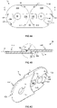
- FIG.1A-1E show a cranked side tab 10, which is made as a one-piece tab body made of plastic by injection molding.
- the side plate 10 has two flat, laterally offset overlapping areas 11A, 11B and a central area 12 at half the length of the chain pitch.
- the middle area 12 has a greater wall thickness compared to the overlapping areas 11A, 11B.
- the first overlapping area 11A has a joint receptacle 13 for the pivotable engagement of a matching joint pin 14 of a side plate 10 of identical construction to be connected.
- the joint pin 14 projects on the outside of the opposite second overlapping area 11B.
- identically dimensioned stop pockets 15A, 15B are provided as recesses in the link body.
- a suitable stop projection 16A, 16B of the respectively adjoining side strap 10 engages in order to limit the relative pivot angle about the pivot axis of the cylindrical pivot pin 14 to the desired width. This is done by stopping the stop projection 16A, 16B in the complementary stop pocket 15A, 15B.
- fastening projections of the side strap 10 for crossbars are not shown.
- the side link 10 can also be part of a chain link that is produced in one piece with an opposite side link that is a mirror image of the side link 10 and is otherwise structurally identical.
- the central region 12 is delimited on both sides in the longitudinal direction of the side strap 10 by a respective end face F11, F12 which runs approximately in the shape of a circular arc around the respective pivot axis and is perpendicular to the main plane H of the strap ( FIG.1D ).
- the inside of the outwardly cranked overlap area 11A forms a flat surface F21 and the outside of the inwardly cranked overlap area 11B forms a further flat surface F21.
- the surfaces F21, F22 are parallel and slightly offset laterally to the main plane H of the link plate, ie the surfaces F21, F22 are perpendicular to the end faces F11, F12.
- the surface F21 of the first overlapping area 11A and the one end face F11 of the central area 12 are connected by a cross-sectional transition Q1.
- the surface F22 of the second overlapping portion 11B and the other end surface F12 of the middle portion 12 are connected by a Connected cross-section transition Q2.
- the cross-sectional profile of the cross-sectional transitions Q1, Q2 is identical according to a transition curve C, which is shown, for example, in FIG.2 is shown in more detail, formed with a shorter leg to the front face F11, F12 and a longer leg to the side faces F21, F22.
- FIG.1E shows another cross-sectional transition Q3 whose profile is characterized by the transition curve C FIG.2 is defined.
- the cross-sectional transition Q3 bridges an effective stop surface F31 as the edge of the stop pocket 15B in the overlapping area 11B and the outer surface F32 of the stop pocket 15B on one side, in FIG.1E to the inside of the chain, closing bottom wall with a relatively small wall thickness or thickness compared to the remaining overlapping area 11B.
- Identically designed cross-sectional transitions Q3 are provided in both stop pockets 15A, 15B on both sides, in each case on the stop surface serving as a counter-stop for the stop projection 16A, 16B.
- complementary cross-sectional transitions can optionally be provided for the cross-sectional transitions Q3 (not shown).
- the cross-sectional transitions Q1, Q2, Q3 according to the transition curve C are optimized with regard to fatigue damage, in particular local stress concentrations or stress peaks caused by the flow of force in the respective area of the link body of the side link 10, since these areas have to withstand constant load changes and/or high forces.
- the cross-sectional transitions Q1, Q2 and Q3 allow a reduction in the material thickness of the link body or a further reduction in the bottom wall of the stop pockets 15A, 15B, or, with the same material thickness, bring about increased operational strength (resistance to repeated load changes) of the adjacent areas of the side link 10.
- the overlapping areas 11A, 11B and the middle area 12 also have cross-sectional transitions to other areas that are not critical with regard to stress peaks, which are rounded as broken edges or conventionally with a radius corresponding to a quarter circle.
- Conventional radius roundings are examples here, for example for the transitions of the lateral surfaces F21, F22 of the overlapping areas 11A, 11B to the upper and lower narrow sides of the side flap 10 ( FIG.1C ) or for the face F11, F12 to the outer side faces of the side flap ( FIG.1D ) shown.
- a preferred transition curve C for constructing the cross-sectional transitions Q1, Q2 and Q3 is in FIG.2 shown, where the transition curve C is to be interpreted scaled on the size ratios.
- the starting point PA of the transition curve C on the one partial surface F11, F21, F31 has a distance A to the intersection curve of the first partial surface with the second partial surface F12, F22, F32, here perpendicular because of vertical partial surfaces, and the end point PZ of the transition curve C the second partial surface F12, F22, F32 a distance Z to the intersection curve of both partial surfaces, here perpendicular to partial surface F11, F21, F31.
- the cross-sectional area of the cross-sectional transition Q1, Q2 or Q3 decreases steadily along the transition curve C from the starting point PA to the end point PZ, here according to a strictly monotonically falling curve.
- the transition curve C is preferably chosen such that 2.3*A ⁇ Z ⁇ 3.4*A is maintained, particularly preferably 2.2*A ⁇ Z ⁇ 2.6.
- the latter is particularly relevant for transitions between vertical surfaces (as in FIG.1A-1E ).
- Other trigonometric functions can also be considered, for example an elliptical segment, provided the curve tangent rotates continuously, preferably strictly monotonically, along the course of the curve in the direction parallel to the second partial surface F12, F22, F32.
- the transition curve C has a tangent at the starting point PA which intersects the first partial surface F11, F21, F31 at an angle of approximately 45° +/- 5°, whereby a residual edge at this point can be left as uncritical to simplify the design.
- FIG.3A-3B show a second embodiment with an inner plate 30A and an outer plate 30B.
- the inner plate 30A is made of plastic in one piece with two overlapping areas 31A, 31B and a central area 32A.
- the outer flap 30B is also produced in one piece with two overlapping areas 31C, 31D and a middle area 32B in an injection molding step.
- the inner link 30A and the outer link 30B are each symmetrical to their vertical center plane and are pivotally connected to one another in an alternating sequence by means of the joint mounts 33, here on the inner link 30A, and the pivot pins 34 here on the outer link 30B.
- the inner plate 30A has on the outside four identically shaped stop pockets 35A, 35B, 35C, 35D distributed rotationally symmetrically about the pivot axis.
- the outer plate 30B has four protruding stop projections 36A, 36B, 36C, 36D on the inside for the purpose of limiting the pivoting angle.
- FIG.1D Analogous to the principle FIG.1D are also after FIG.3A End faces F11 of the central area 32A of the inner plate 30A with cross-sectional transitions Q1 into lateral faces F21 of the overlapping areas 31A, 31B perpendicular to the end faces F11.
- the cross-section transitions Q1 are scaled accordingly, according to the transition curve C from FIG.2 executed.
- the outer plate 30B has further cross-sectional transitions Q4 according to the invention at the stop projections 36A, 36B, 36C, 36D.
- the cross-sectional transitions Q4 each lie circumferentially at the base of the stop projections 36A, 36B, 36C, 36D and correspond a scaled transition curve C FIG.2 .
- Cross-section transitions accordingly FIG.1E can also be used in the attachment pockets 35A, 35B, 35C, 35D.
- FIG.3A-3B two material recesses 37A on the outside of the middle region 32A of the inner link 30A and four further rotationally symmetrically arranged and identically designed material recesses 37B in the outer link 30B.
- the use of cross-sectional transitions Q5 according to a transition curve C according to the invention FIG.2 for the inward transition into these material recesses 37A, 37B enables better material utilization in the link body of the inner link 30A and the outer link 30B and thus at the same time a noticeable reduction in the component mass or the required amount of plastic per link, which lowers material costs and can increase the cycle times of the injection molding machine.
Landscapes
- Engineering & Computer Science (AREA)
- General Engineering & Computer Science (AREA)
- Mechanical Engineering (AREA)
- Moulds For Moulding Plastics Or The Like (AREA)
- Injection Moulding Of Plastics Or The Like (AREA)
- Details Of Indoor Wiring (AREA)
- Electric Cable Arrangement Between Relatively Moving Parts (AREA)
- Exhaust Gas Treatment By Means Of Catalyst (AREA)
- Devices For Conveying Motion By Means Of Endless Flexible Members (AREA)
- Chain Conveyers (AREA)
Applications Claiming Priority (2)
| Application Number | Priority Date | Filing Date | Title |
|---|---|---|---|
| DE202019100465.7U DE202019100465U1 (de) | 2019-01-25 | 2019-01-25 | Betriebsfest ausgelegte Seitenlasche für eine Energieführungskette |
| PCT/EP2020/051520 WO2020152221A1 (de) | 2019-01-25 | 2020-01-22 | Betriebsfest ausgelegte seitenlasche für eine energieführungskette |
Publications (2)
| Publication Number | Publication Date |
|---|---|
| EP3894720A1 EP3894720A1 (de) | 2021-10-20 |
| EP3894720B1 true EP3894720B1 (de) | 2022-06-08 |
Family
ID=66816844
Family Applications (1)
| Application Number | Title | Priority Date | Filing Date |
|---|---|---|---|
| EP20704781.2A Active EP3894720B1 (de) | 2019-01-25 | 2020-01-22 | Betriebsfest ausgelegte seitenlasche für eine energieführungskette |
Country Status (12)
| Country | Link |
|---|---|
| US (1) | US12085203B2 (pl) |
| EP (1) | EP3894720B1 (pl) |
| JP (1) | JP7464610B2 (pl) |
| KR (1) | KR102799595B1 (pl) |
| CN (1) | CN113795686B (pl) |
| CA (1) | CA3127646C (pl) |
| DE (1) | DE202019100465U1 (pl) |
| ES (1) | ES2924310T3 (pl) |
| MY (1) | MY204793A (pl) |
| PL (1) | PL3894720T3 (pl) |
| SG (1) | SG11202108117TA (pl) |
| WO (1) | WO2020152221A1 (pl) |
Families Citing this family (2)
| Publication number | Priority date | Publication date | Assignee | Title |
|---|---|---|---|---|
| DE202019100466U1 (de) * | 2019-01-25 | 2019-05-28 | Igus Gmbh | Energieführungskette mit seitenstabilisierten Laschen |
| KR102720404B1 (ko) * | 2022-08-12 | 2024-10-21 | 김현우 | 로보체인 |
Family Cites Families (18)
| Publication number | Priority date | Publication date | Assignee | Title |
|---|---|---|---|---|
| DE2126255A1 (de) * | 1971-05-26 | 1972-12-07 | Gebr Hennig GmbH, 8045 Ismamng | Gliederkette |
| DE2255283C3 (de) * | 1972-11-11 | 1975-06-05 | Kabelschlepp Gmbh, 5900 Siegen | Energieführungskette |
| IT1121572B (it) * | 1979-06-08 | 1986-04-02 | Mauri Giovanni | Catena portacavi ad elementi monoblocco |
| DE3139735A1 (de) | 1981-10-06 | 1983-04-21 | Ernst 4000 Düsseldorf Klein | Kabelfuehrungskette |
| DE3531066A1 (de) | 1985-08-30 | 1987-03-12 | Igus Gmbh | Energiezufuehrungskette |
| DE3928236C1 (pl) | 1989-08-26 | 1990-10-25 | Kabelschlepp Gmbh, 5900 Siegen, De | |
| DE4325259C2 (de) * | 1993-07-28 | 1995-07-20 | Igus Gmbh | Energieführungskette |
| JPH10238599A (ja) * | 1997-02-25 | 1998-09-08 | Kunimori Kagaku Co Ltd | ケーブルチェーン |
| US6190277B1 (en) * | 1997-07-10 | 2001-02-20 | Igus Spritzgussteile für die Industrie GmbH | Energy transmission chain |
| DE20002820U1 (de) | 2000-02-16 | 2000-05-25 | Igus Spritzgußteile für die Industrie GmbH, 51147 Köln | Energieführungskette |
| US6978595B2 (en) * | 2002-02-05 | 2005-12-27 | Delphi Technologies, Inc. | Chain links and cable carrier chains containing same |
| DE10339168A1 (de) * | 2003-08-21 | 2005-04-28 | Kabelschlepp Gmbh | Kettenlasche für eine Energieführungskette sowie Energieführungskette |
| DE102008060466A1 (de) * | 2008-12-05 | 2010-06-10 | Kabelschlepp Gmbh | Kettenglied für eine Energieführungskette und Verfahren zur Herstellung eines Quersteges für ein solches Kettenglied |
| DE102011082243A1 (de) | 2011-09-07 | 2013-03-07 | Zf Friedrichshafen Ag | Lagerungs- oder Kraftübertragungsbauteil mit Querschnittsübergang |
| DE102012006446B4 (de) * | 2012-03-30 | 2020-06-04 | Tsubaki Kabelschlepp GmbH | Metallische Lasche eines Kettenglieds einer Energieführungskette |
| DE202012003903U1 (de) * | 2012-04-19 | 2012-05-25 | Igus Gmbh | Energieführungskette mit Rollen |
| DE202014101366U1 (de) * | 2014-03-24 | 2014-03-28 | Igus Gmbh | Leitungsführungseinrichtung mit einstückigem Gelenk, entsprechendes Kettenglied und Gelenkband |
| DE202014104075U1 (de) * | 2014-09-01 | 2014-09-09 | Igus Gmbh | Leitungsführungseinrichtung |
-
2019
- 2019-01-25 DE DE202019100465.7U patent/DE202019100465U1/de active Active
-
2020
- 2020-01-22 ES ES20704781T patent/ES2924310T3/es active Active
- 2020-01-22 PL PL20704781.2T patent/PL3894720T3/pl unknown
- 2020-01-22 CN CN202080015388.6A patent/CN113795686B/zh active Active
- 2020-01-22 MY MYPI2021004228A patent/MY204793A/en unknown
- 2020-01-22 US US17/310,178 patent/US12085203B2/en active Active
- 2020-01-22 CA CA3127646A patent/CA3127646C/en active Active
- 2020-01-22 JP JP2021542383A patent/JP7464610B2/ja active Active
- 2020-01-22 KR KR1020217026899A patent/KR102799595B1/ko active Active
- 2020-01-22 EP EP20704781.2A patent/EP3894720B1/de active Active
- 2020-01-22 WO PCT/EP2020/051520 patent/WO2020152221A1/de not_active Ceased
- 2020-01-22 SG SG11202108117TA patent/SG11202108117TA/en unknown
Also Published As
| Publication number | Publication date |
|---|---|
| DE202019100465U1 (de) | 2019-05-28 |
| CN113795686A (zh) | 2021-12-14 |
| BR112021013937A2 (pt) | 2021-09-21 |
| SG11202108117TA (en) | 2021-08-30 |
| US12085203B2 (en) | 2024-09-10 |
| CA3127646C (en) | 2024-05-14 |
| ES2924310T3 (es) | 2022-10-05 |
| MY204793A (en) | 2024-09-13 |
| JP7464610B2 (ja) | 2024-04-09 |
| EP3894720A1 (de) | 2021-10-20 |
| CA3127646A1 (en) | 2020-07-30 |
| JP2022519187A (ja) | 2022-03-22 |
| WO2020152221A1 (de) | 2020-07-30 |
| KR20210119483A (ko) | 2021-10-05 |
| PL3894720T3 (pl) | 2022-11-14 |
| CN113795686B (zh) | 2023-06-23 |
| KR102799595B1 (ko) | 2025-04-28 |
| US20220082184A1 (en) | 2022-03-17 |
Similar Documents
| Publication | Publication Date | Title |
|---|---|---|
| EP1975093B1 (de) | Seitenbogenförderkette mit Innen- und Außenkettengliedern | |
| EP1503107B2 (de) | Gelenkelement für Energieführungskette | |
| EP0803032B1 (de) | Energieführungskette | |
| EP2694841B1 (de) | Energieführungskette mit deformierbaren gelenkelementen | |
| EP1283381B1 (de) | Energieführungskette und Kettenglied | |
| DE19710489A1 (de) | Faltbares Schutzelement für Leitungen | |
| DE4325259C2 (de) | Energieführungskette | |
| DE19647322A1 (de) | Kettenglied aus verschiedenen Werkstoffen und Verfahren zu dessen Herstellung | |
| EP3789635B1 (de) | Zahnrad | |
| DE102007018501A1 (de) | Laschenkette | |
| WO2013174666A1 (de) | Gurtendekörper oder gurtsegmentendekörper | |
| EP3069423B1 (de) | Leitungsführung | |
| DE202017101466U1 (de) | Mit einem Kettenantrieb betätigbare rückensteife Schubkette | |
| EP3115642B1 (de) | Gurt oder gurtsegment | |
| EP3894721B1 (de) | Energieführungskette mit seitenstabilisierten laschen aus kunststoff | |
| WO2020152221A1 (de) | Betriebsfest ausgelegte seitenlasche für eine energieführungskette | |
| DE102016111542B4 (de) | Schubkette mit standardisiertem Endstück | |
| WO2015070974A1 (de) | Gummibandkettensegment | |
| EP4259951B1 (de) | Energiefuhrüngsketten für lange verfahrwege, insbesondere mit laufrollen | |
| EP1999396B1 (de) | Verzugsfreies kettenglied | |
| EP2927162B1 (de) | Modulglied für ein Förderband und Förderband aus gelenkig miteinander verbundenen Modulgliedern | |
| DE202017105244U1 (de) | Energieführungskette mit in die Gelenkverbindungen integrierten Schwenkwinkel-Anschlägen und entsprechende Kettenlaschen | |
| WO2026078013A1 (de) | Energieführungskette und seitenlasche mit seitenstabilisierung | |
| DE202021101933U1 (de) | Energieführungskette mit biegsamen Gelenkverbindern, sowie Seitenlaschen und Gelenkverbinder hierfür | |
| EP4695532A1 (de) | Leitungsführungseinrichtung mit kabelbinder |
Legal Events
| Date | Code | Title | Description |
|---|---|---|---|
| STAA | Information on the status of an ep patent application or granted ep patent |
Free format text: STATUS: UNKNOWN |
|
| STAA | Information on the status of an ep patent application or granted ep patent |
Free format text: STATUS: THE INTERNATIONAL PUBLICATION HAS BEEN MADE |
|
| PUAI | Public reference made under article 153(3) epc to a published international application that has entered the european phase |
Free format text: ORIGINAL CODE: 0009012 |
|
| STAA | Information on the status of an ep patent application or granted ep patent |
Free format text: STATUS: REQUEST FOR EXAMINATION WAS MADE |
|
| 17P | Request for examination filed |
Effective date: 20210711 |
|
| AK | Designated contracting states |
Kind code of ref document: A1 Designated state(s): AL AT BE BG CH CY CZ DE DK EE ES FI FR GB GR HR HU IE IS IT LI LT LU LV MC MK MT NL NO PL PT RO RS SE SI SK SM TR |
|
| GRAP | Despatch of communication of intention to grant a patent |
Free format text: ORIGINAL CODE: EPIDOSNIGR1 |
|
| STAA | Information on the status of an ep patent application or granted ep patent |
Free format text: STATUS: GRANT OF PATENT IS INTENDED |
|
| INTG | Intention to grant announced |
Effective date: 20220127 |
|
| GRAS | Grant fee paid |
Free format text: ORIGINAL CODE: EPIDOSNIGR3 |
|
| DAV | Request for validation of the european patent (deleted) | ||
| DAX | Request for extension of the european patent (deleted) | ||
| GRAA | (expected) grant |
Free format text: ORIGINAL CODE: 0009210 |
|
| STAA | Information on the status of an ep patent application or granted ep patent |
Free format text: STATUS: THE PATENT HAS BEEN GRANTED |
|
| AK | Designated contracting states |
Kind code of ref document: B1 Designated state(s): AL AT BE BG CH CY CZ DE DK EE ES FI FR GB GR HR HU IE IS IT LI LT LU LV MC MK MT NL NO PL PT RO RS SE SI SK SM TR |
|
| REG | Reference to a national code |
Ref country code: AT Ref legal event code: REF Ref document number: 1497139 Country of ref document: AT Kind code of ref document: T Effective date: 20220615 Ref country code: CH Ref legal event code: EP |
|
| REG | Reference to a national code |
Ref country code: DE Ref legal event code: R096 Ref document number: 502020001213 Country of ref document: DE |
|
| REG | Reference to a national code |
Ref country code: IE Ref legal event code: FG4D Free format text: LANGUAGE OF EP DOCUMENT: GERMAN |
|
| REG | Reference to a national code |
Ref country code: NL Ref legal event code: FP |
|
| REG | Reference to a national code |
Ref country code: LT Ref legal event code: MG9D |
|
| REG | Reference to a national code |
Ref country code: ES Ref legal event code: FG2A Ref document number: 2924310 Country of ref document: ES Kind code of ref document: T3 Effective date: 20221005 |
|
| PG25 | Lapsed in a contracting state [announced via postgrant information from national office to epo] |
Ref country code: SE Free format text: LAPSE BECAUSE OF FAILURE TO SUBMIT A TRANSLATION OF THE DESCRIPTION OR TO PAY THE FEE WITHIN THE PRESCRIBED TIME-LIMIT Effective date: 20220608 Ref country code: NO Free format text: LAPSE BECAUSE OF FAILURE TO SUBMIT A TRANSLATION OF THE DESCRIPTION OR TO PAY THE FEE WITHIN THE PRESCRIBED TIME-LIMIT Effective date: 20220908 Ref country code: LT Free format text: LAPSE BECAUSE OF FAILURE TO SUBMIT A TRANSLATION OF THE DESCRIPTION OR TO PAY THE FEE WITHIN THE PRESCRIBED TIME-LIMIT Effective date: 20220608 Ref country code: HR Free format text: LAPSE BECAUSE OF FAILURE TO SUBMIT A TRANSLATION OF THE DESCRIPTION OR TO PAY THE FEE WITHIN THE PRESCRIBED TIME-LIMIT Effective date: 20220608 Ref country code: GR Free format text: LAPSE BECAUSE OF FAILURE TO SUBMIT A TRANSLATION OF THE DESCRIPTION OR TO PAY THE FEE WITHIN THE PRESCRIBED TIME-LIMIT Effective date: 20220909 Ref country code: FI Free format text: LAPSE BECAUSE OF FAILURE TO SUBMIT A TRANSLATION OF THE DESCRIPTION OR TO PAY THE FEE WITHIN THE PRESCRIBED TIME-LIMIT Effective date: 20220608 Ref country code: BG Free format text: LAPSE BECAUSE OF FAILURE TO SUBMIT A TRANSLATION OF THE DESCRIPTION OR TO PAY THE FEE WITHIN THE PRESCRIBED TIME-LIMIT Effective date: 20220908 |
|
| PG25 | Lapsed in a contracting state [announced via postgrant information from national office to epo] |
Ref country code: RS Free format text: LAPSE BECAUSE OF FAILURE TO SUBMIT A TRANSLATION OF THE DESCRIPTION OR TO PAY THE FEE WITHIN THE PRESCRIBED TIME-LIMIT Effective date: 20220608 Ref country code: LV Free format text: LAPSE BECAUSE OF FAILURE TO SUBMIT A TRANSLATION OF THE DESCRIPTION OR TO PAY THE FEE WITHIN THE PRESCRIBED TIME-LIMIT Effective date: 20220608 |
|
| PG25 | Lapsed in a contracting state [announced via postgrant information from national office to epo] |
Ref country code: SM Free format text: LAPSE BECAUSE OF FAILURE TO SUBMIT A TRANSLATION OF THE DESCRIPTION OR TO PAY THE FEE WITHIN THE PRESCRIBED TIME-LIMIT Effective date: 20220608 Ref country code: SK Free format text: LAPSE BECAUSE OF FAILURE TO SUBMIT A TRANSLATION OF THE DESCRIPTION OR TO PAY THE FEE WITHIN THE PRESCRIBED TIME-LIMIT Effective date: 20220608 Ref country code: RO Free format text: LAPSE BECAUSE OF FAILURE TO SUBMIT A TRANSLATION OF THE DESCRIPTION OR TO PAY THE FEE WITHIN THE PRESCRIBED TIME-LIMIT Effective date: 20220608 Ref country code: PT Free format text: LAPSE BECAUSE OF FAILURE TO SUBMIT A TRANSLATION OF THE DESCRIPTION OR TO PAY THE FEE WITHIN THE PRESCRIBED TIME-LIMIT Effective date: 20221010 Ref country code: EE Free format text: LAPSE BECAUSE OF FAILURE TO SUBMIT A TRANSLATION OF THE DESCRIPTION OR TO PAY THE FEE WITHIN THE PRESCRIBED TIME-LIMIT Effective date: 20220608 Ref country code: CZ Free format text: LAPSE BECAUSE OF FAILURE TO SUBMIT A TRANSLATION OF THE DESCRIPTION OR TO PAY THE FEE WITHIN THE PRESCRIBED TIME-LIMIT Effective date: 20220608 |
|
| PG25 | Lapsed in a contracting state [announced via postgrant information from national office to epo] |
Ref country code: IS Free format text: LAPSE BECAUSE OF FAILURE TO SUBMIT A TRANSLATION OF THE DESCRIPTION OR TO PAY THE FEE WITHIN THE PRESCRIBED TIME-LIMIT Effective date: 20221008 |
|
| REG | Reference to a national code |
Ref country code: DE Ref legal event code: R097 Ref document number: 502020001213 Country of ref document: DE |
|
| PG25 | Lapsed in a contracting state [announced via postgrant information from national office to epo] |
Ref country code: AL Free format text: LAPSE BECAUSE OF FAILURE TO SUBMIT A TRANSLATION OF THE DESCRIPTION OR TO PAY THE FEE WITHIN THE PRESCRIBED TIME-LIMIT Effective date: 20220608 |
|
| PLBE | No opposition filed within time limit |
Free format text: ORIGINAL CODE: 0009261 |
|
| STAA | Information on the status of an ep patent application or granted ep patent |
Free format text: STATUS: NO OPPOSITION FILED WITHIN TIME LIMIT |
|
| PG25 | Lapsed in a contracting state [announced via postgrant information from national office to epo] |
Ref country code: DK Free format text: LAPSE BECAUSE OF FAILURE TO SUBMIT A TRANSLATION OF THE DESCRIPTION OR TO PAY THE FEE WITHIN THE PRESCRIBED TIME-LIMIT Effective date: 20220608 |
|
| 26N | No opposition filed |
Effective date: 20230310 |
|
| P01 | Opt-out of the competence of the unified patent court (upc) registered |
Effective date: 20230526 |
|
| PG25 | Lapsed in a contracting state [announced via postgrant information from national office to epo] |
Ref country code: LU Free format text: LAPSE BECAUSE OF NON-PAYMENT OF DUE FEES Effective date: 20230122 |
|
| REG | Reference to a national code |
Ref country code: BE Ref legal event code: MM Effective date: 20230131 |
|
| PG25 | Lapsed in a contracting state [announced via postgrant information from national office to epo] |
Ref country code: BE Free format text: LAPSE BECAUSE OF NON-PAYMENT OF DUE FEES Effective date: 20230131 |
|
| PG25 | Lapsed in a contracting state [announced via postgrant information from national office to epo] |
Ref country code: IE Free format text: LAPSE BECAUSE OF NON-PAYMENT OF DUE FEES Effective date: 20230122 |
|
| PG25 | Lapsed in a contracting state [announced via postgrant information from national office to epo] |
Ref country code: MC Free format text: LAPSE BECAUSE OF FAILURE TO SUBMIT A TRANSLATION OF THE DESCRIPTION OR TO PAY THE FEE WITHIN THE PRESCRIBED TIME-LIMIT Effective date: 20220608 |
|
| PG25 | Lapsed in a contracting state [announced via postgrant information from national office to epo] |
Ref country code: MC Free format text: LAPSE BECAUSE OF FAILURE TO SUBMIT A TRANSLATION OF THE DESCRIPTION OR TO PAY THE FEE WITHIN THE PRESCRIBED TIME-LIMIT Effective date: 20220608 |
|
| PG25 | Lapsed in a contracting state [announced via postgrant information from national office to epo] |
Ref country code: BG Free format text: LAPSE BECAUSE OF FAILURE TO SUBMIT A TRANSLATION OF THE DESCRIPTION OR TO PAY THE FEE WITHIN THE PRESCRIBED TIME-LIMIT Effective date: 20220608 |
|
| PG25 | Lapsed in a contracting state [announced via postgrant information from national office to epo] |
Ref country code: BG Free format text: LAPSE BECAUSE OF FAILURE TO SUBMIT A TRANSLATION OF THE DESCRIPTION OR TO PAY THE FEE WITHIN THE PRESCRIBED TIME-LIMIT Effective date: 20220608 |
|
| PG25 | Lapsed in a contracting state [announced via postgrant information from national office to epo] |
Ref country code: CY Free format text: LAPSE BECAUSE OF FAILURE TO SUBMIT A TRANSLATION OF THE DESCRIPTION OR TO PAY THE FEE WITHIN THE PRESCRIBED TIME-LIMIT; INVALID AB INITIO Effective date: 20200122 |
|
| PG25 | Lapsed in a contracting state [announced via postgrant information from national office to epo] |
Ref country code: HU Free format text: LAPSE BECAUSE OF FAILURE TO SUBMIT A TRANSLATION OF THE DESCRIPTION OR TO PAY THE FEE WITHIN THE PRESCRIBED TIME-LIMIT; INVALID AB INITIO Effective date: 20200122 |
|
| PG25 | Lapsed in a contracting state [announced via postgrant information from national office to epo] |
Ref country code: TR Free format text: LAPSE BECAUSE OF FAILURE TO SUBMIT A TRANSLATION OF THE DESCRIPTION OR TO PAY THE FEE WITHIN THE PRESCRIBED TIME-LIMIT Effective date: 20220608 |
|
| REG | Reference to a national code |
Ref country code: CH Ref legal event code: U11 Free format text: ST27 STATUS EVENT CODE: U-0-0-U10-U11 (AS PROVIDED BY THE NATIONAL OFFICE) Effective date: 20260201 |
|
| REG | Reference to a national code |
Ref country code: DE Ref legal event code: R081 Ref document number: 502020001213 Country of ref document: DE Owner name: IGUS SE & CO. KG, DE Free format text: FORMER OWNER: IGUS GMBH, 51147 KOELN, DE |
|
| PG25 | Lapsed in a contracting state [announced via postgrant information from national office to epo] |
Ref country code: SI Free format text: LAPSE BECAUSE OF FAILURE TO SUBMIT A TRANSLATION OF THE DESCRIPTION OR TO PAY THE FEE WITHIN THE PRESCRIBED TIME-LIMIT Effective date: 20220608 |
|
| PGFP | Annual fee paid to national office [announced via postgrant information from national office to epo] |
Ref country code: NL Payment date: 20260121 Year of fee payment: 7 |
|
| PGFP | Annual fee paid to national office [announced via postgrant information from national office to epo] |
Ref country code: GB Payment date: 20260122 Year of fee payment: 7 |
|
| PGFP | Annual fee paid to national office [announced via postgrant information from national office to epo] |
Ref country code: ES Payment date: 20260217 Year of fee payment: 7 |
|
| PGFP | Annual fee paid to national office [announced via postgrant information from national office to epo] |
Ref country code: DE Payment date: 20260327 Year of fee payment: 7 |
|
| PGFP | Annual fee paid to national office [announced via postgrant information from national office to epo] |
Ref country code: AT Payment date: 20260119 Year of fee payment: 7 |
|
| PGFP | Annual fee paid to national office [announced via postgrant information from national office to epo] |
Ref country code: IT Payment date: 20260130 Year of fee payment: 7 |
|
| PGFP | Annual fee paid to national office [announced via postgrant information from national office to epo] |
Ref country code: FR Payment date: 20260128 Year of fee payment: 7 |
|
| PGFP | Annual fee paid to national office [announced via postgrant information from national office to epo] |
Ref country code: CH Payment date: 20260201 Year of fee payment: 7 |
|
| PGFP | Annual fee paid to national office [announced via postgrant information from national office to epo] |
Ref country code: PL Payment date: 20260109 Year of fee payment: 7 |