EP3894720B1 - Operationally stable side plate for an energy chain - Google Patents
Operationally stable side plate for an energy chain Download PDFInfo
- Publication number
- EP3894720B1 EP3894720B1 EP20704781.2A EP20704781A EP3894720B1 EP 3894720 B1 EP3894720 B1 EP 3894720B1 EP 20704781 A EP20704781 A EP 20704781A EP 3894720 B1 EP3894720 B1 EP 3894720B1
- Authority
- EP
- European Patent Office
- Prior art keywords
- subsurface
- transition
- curve
- cross
- side plate
- Prior art date
- Legal status (The legal status is an assumption and is not a legal conclusion. Google has not performed a legal analysis and makes no representation as to the accuracy of the status listed.)
- Active
Links
- 230000007704 transition Effects 0.000 claims description 126
- 239000000463 material Substances 0.000 claims description 23
- 239000004033 plastic Substances 0.000 claims description 11
- 229920003023 plastic Polymers 0.000 claims description 11
- 238000001746 injection moulding Methods 0.000 claims description 6
- 230000000694 effects Effects 0.000 claims description 3
- 230000007423 decrease Effects 0.000 claims description 2
- 229920001169 thermoplastic Polymers 0.000 claims 1
- 239000004416 thermosoftening plastic Substances 0.000 claims 1
- 230000036961 partial effect Effects 0.000 description 37
- 206010016256 fatigue Diseases 0.000 description 9
- 230000005540 biological transmission Effects 0.000 description 6
- 238000013461 design Methods 0.000 description 6
- 239000002184 metal Substances 0.000 description 6
- 230000009467 reduction Effects 0.000 description 5
- 230000000295 complement effect Effects 0.000 description 4
- 238000010276 construction Methods 0.000 description 4
- 230000002349 favourable effect Effects 0.000 description 4
- 238000004519 manufacturing process Methods 0.000 description 3
- 238000000034 method Methods 0.000 description 2
- 230000008569 process Effects 0.000 description 2
- 230000002829 reductive effect Effects 0.000 description 2
- 208000016261 weight loss Diseases 0.000 description 2
- 208000010392 Bone Fractures Diseases 0.000 description 1
- 206010017076 Fracture Diseases 0.000 description 1
- 238000012356 Product development Methods 0.000 description 1
- 229910000831 Steel Inorganic materials 0.000 description 1
- 208000013201 Stress fracture Diseases 0.000 description 1
- 238000010521 absorption reaction Methods 0.000 description 1
- 230000004308 accommodation Effects 0.000 description 1
- 238000013459 approach Methods 0.000 description 1
- 230000002146 bilateral effect Effects 0.000 description 1
- 239000000969 carrier Substances 0.000 description 1
- 230000003247 decreasing effect Effects 0.000 description 1
- 238000009795 derivation Methods 0.000 description 1
- 238000005516 engineering process Methods 0.000 description 1
- 229920005570 flexible polymer Polymers 0.000 description 1
- 238000010230 functional analysis Methods 0.000 description 1
- 238000009434 installation Methods 0.000 description 1
- 230000003993 interaction Effects 0.000 description 1
- 238000011835 investigation Methods 0.000 description 1
- 230000000670 limiting effect Effects 0.000 description 1
- 230000007774 longterm Effects 0.000 description 1
- 239000007769 metal material Substances 0.000 description 1
- 238000005457 optimization Methods 0.000 description 1
- 238000012805 post-processing Methods 0.000 description 1
- 230000003068 static effect Effects 0.000 description 1
- 239000010959 steel Substances 0.000 description 1
- 238000012360 testing method Methods 0.000 description 1
- 239000012815 thermoplastic material Substances 0.000 description 1
- 239000013585 weight reducing agent Substances 0.000 description 1
Images


Classifications
-
- F—MECHANICAL ENGINEERING; LIGHTING; HEATING; WEAPONS; BLASTING
- F16—ENGINEERING ELEMENTS AND UNITS; GENERAL MEASURES FOR PRODUCING AND MAINTAINING EFFECTIVE FUNCTIONING OF MACHINES OR INSTALLATIONS; THERMAL INSULATION IN GENERAL
- F16L—PIPES; JOINTS OR FITTINGS FOR PIPES; SUPPORTS FOR PIPES, CABLES OR PROTECTIVE TUBING; MEANS FOR THERMAL INSULATION IN GENERAL
- F16L3/00—Supports for pipes, cables or protective tubing, e.g. hangers, holders, clamps, cleats, clips, brackets
- F16L3/01—Supports for pipes, cables or protective tubing, e.g. hangers, holders, clamps, cleats, clips, brackets for supporting or guiding the pipes, cables or protective tubing, between relatively movable points, e.g. movable channels
- F16L3/015—Supports for pipes, cables or protective tubing, e.g. hangers, holders, clamps, cleats, clips, brackets for supporting or guiding the pipes, cables or protective tubing, between relatively movable points, e.g. movable channels using articulated- or supple-guiding elements
-
- F—MECHANICAL ENGINEERING; LIGHTING; HEATING; WEAPONS; BLASTING
- F16—ENGINEERING ELEMENTS AND UNITS; GENERAL MEASURES FOR PRODUCING AND MAINTAINING EFFECTIVE FUNCTIONING OF MACHINES OR INSTALLATIONS; THERMAL INSULATION IN GENERAL
- F16G—BELTS, CABLES, OR ROPES, PREDOMINANTLY USED FOR DRIVING PURPOSES; CHAINS; FITTINGS PREDOMINANTLY USED THEREFOR
- F16G13/00—Chains
- F16G13/12—Hauling- or hoisting-chains so called ornamental chains
- F16G13/16—Hauling- or hoisting-chains so called ornamental chains with arrangements for holding electric cables, hoses, or the like
-
- H—ELECTRICITY
- H02—GENERATION; CONVERSION OR DISTRIBUTION OF ELECTRIC POWER
- H02G—INSTALLATION OF ELECTRIC CABLES OR LINES, OR OF COMBINED OPTICAL AND ELECTRIC CABLES OR LINES
- H02G11/00—Arrangements of electric cables or lines between relatively-movable parts
- H02G11/006—Arrangements of electric cables or lines between relatively-movable parts using extensible carrier for the cable, e.g. self-coiling spring
Definitions
- the invention generally relates to a side plate for an energy guiding chain.
- Energy guiding chains are used for the dynamic and protected routing of flexible lines, such as hoses, cables or the like, between two relatively movable connection points.
- Energy guiding chains are made from chain links, each of which typically includes two opposite side plates, which are connected to one another in a fixed or detachable manner via a crosspiece or two opposite crosspieces.
- the tab body of generic side tabs has two overlap areas, each for pivotal connection to a corresponding overlap area of an adjacent tab, and a central area therebetween.
- Chain links each with two opposite, fork-shaped chain straps that are connected to each other via crossbars.
- the link plates consist of two side plates, each of which is produced as a flat stamped sheet metal part.
- Each of the two side links has a one-piece link body made of sheet metal, eg typically sheet steel, with two overlapping areas for pivotable connection with a corresponding overlapping area of an adjacent link plate, and with a middle area between the overlapping areas.
- the two overlapping areas or end areas of the two side straps are cranked in opposite directions to one another or offset laterally, according to FIG DE 31 39 735 A1 by the thickness of the link plate. Between the overlapping areas and the central area there are cross-sectional transitions which are rounded, for example by a forming process to produce a lateral offset or the desired cranking.
- a side plate made of sheet metal is from WO 2007 118 574 A1 known, here, too, cross-sectional transitions between cranked overlapping areas are rounded on the outer surfaces by production in a forming process.
- Sheet metal side tabs have high strength, especially tensile strength.
- the geometry of a side flap is always chosen depending on the respective material and the manufacturing process, among other things.
- Two types of plastic side straps are often used: complementary inner and outer straps, which are alternately connected to one another in the longitudinal direction to form a strap strand, such as in WO 95/04231 A1 described, or in top view cranked side flaps, such as in DE 3 531 066 C2 or. US 4,813,224A described. Both tab types can each be manufactured inexpensively using injection molding technology.
- the side flaps each have a number of cross-sectional transitions in the overlapping area and/or central area, each between two sub-areas of the outer surfaces, since these are at an angle, due to their function, in particular perpendicular to each other or run.
- cross-sectional transitions It is common practice to produce certain of these cross-sectional transitions rounded, in particular to avoid sheep-edged transitions or to smooth out edges. For example, transitions from the large side surfaces to the narrow sides are rounded, for example to avoid protruding edges, or the free front ends of the pivot pins to facilitate assembly.
- the rounding of cross-section transitions typically takes place as a radius transition with a small radius in the form of a quarter-circle arc, which is applied symmetrically to the partial areas.
- side links are exposed to very high forces during operation of the energy guiding chain, especially with long guide lengths or travel distances and/or high speeds.
- forces arise, among other things, from the traction transmission necessary for movement, but also, for example, at the stops to limit the swivel angle, for example in self-supporting applications (with an upper strand self-supporting at a distance above a lower strand) or in the deflection bend between the chain strands.
- the stress or load on the side straps is fundamentally dynamic and often repeated at high rates, mostly cyclically, due to the back and forth movement of the moving strand. In such cases, there is an increased risk of fatigue damage due to load changes.
- a first object of the present invention is therefore to further develop generic plastic side plates for power transmission chains without oversizing or the need for a stronger design using additional material such that they nevertheless have increased fatigue strength.
- the possibility should be opened up for further weight savings by reducing the wall thicknesses or the plastic mass in the side flap.
- a specially shaped cross-sectional transition is provided on at least one area intended for load absorption and identified as critical with a first and a second partial surface of the link body, be it at the overlapping areas, at the central area, or at the transition between the overlapping area and the central area.
- this selected cross-sectional transition is defined by an enveloping transition curve with a special course, with the cross-sectional area of the cross-sectional transition steadily decreasing along the transition curve from the starting point to the end point, in particular falling monotonously (in the sense of the corresponding curve function).
- the course of the transition curve according to the invention is set in such a way that for a selected starting point of the transition curve in or on the first partial area, which is at a distance A from the imaginary intersection curve of the first partial area with the second partial area, the end point of the curve is in or on the second partial area lies at a predetermined, greater distance Z from this intersection curve, namely a distance Z with 1.7 A ⁇ Z ⁇ 4.0 A, in particular with 2.3 A ⁇ Z ⁇ 3.4 A.
- the transition in the cross section is designed according to a monotonically falling curve, which is selected or constructed according to the invention in such a way that the end point distance Z to Intersection curve of both adjacent surfaces is significantly larger than their corresponding starting point distance A, specifically in the range 1.7 ⁇ Z/A ⁇ 4.0.
- Such a cross-sectional transition is significantly more favorable with regard to fatigue damage, in particular local stress concentrations or stress peaks caused by the flow of force, than conventionally applied quadrant radii of curvature.
- the cross-section transition can be scaled and adapted to any installation space or boundary conditions.
- the intersection curve for which the distance between the start and end point is considered, corresponds to a straight line of intersection.
- the intersection curve is not a straight line.
- the enveloping transition curve is preferably constant at least in regions or predominantly along the cross-sectional transition, i.e. an enveloping curve to the outer surface of the cross-sectional transition.
- the transition curve corresponds to a smooth or stepless and strictly monotonically falling curve in the sense of a functional analysis or mathematically.
- the radius of curvature can be constant at least in certain areas along the curve. It is also possible to use a curve with continuous curvature in some areas or with a starting point distance A and an end point distance Z in the ratio range 1.7 ⁇ Z/A ⁇ 4.0.
- the invention also relates to a cross-sectional transition, regardless of the distance ratio Z/A, defined by a transition curve that is smooth (stepless) and strictly monotonically falling and is characterized by special properties of its curve tangent or curve slope (or first derivative) relevant to the flow of forces or differential quotient) along its course.
- a transition curve is selected whose tangent at the starting point (viewed from the extreme) intersects the first surface at an angle of approx.
- the transition curve can include several continuously merging, e.g.
- cross-sectional transitions shaped according to the invention enables the production of side straps designed to be operationally stable, without additional material expenditure. Material savings can also be achieved, in particular compared to existing designs of side straps, by avoiding unnecessary oversizing or eliminating it in a targeted manner.
- a first point that is critical with regard to fatigue failure is at the transition between the overlapping area and the typically thicker middle area, ie in a preferred embodiment the first partial area has the starting point at the middle area and the second partial area has the end point at one overlap area.
- the cross-sectional transition can therefore be provided in particular at the transition between a smaller wall thickness of this overlapping area and a larger wall thickness of the central area. Accordingly, a correspondingly fitting contour can be provided at the front end of the side straps in order to ensure the required freedom of movement.
- High force namely alternating tensile and shear force
- the side link particularly in the case of long chains and in the first third of the power transmission chain on the driver side. Due to changes in wall thickness and/or lateral offset of the overlapping areas, both transitions to the middle area are exposed to pronounced loads.
- a second point that is critical with regard to fatigue failure is in the stop pockets or stop recesses, which form counter stops for corresponding stop projections of the immediately adjacent or overlapping strap.
- a stop projection engages in the stop recess in order to limit the swivel angle, typically in both swivel directions.
- the floor transition in stop recesses has an increased risk of breakage, particularly in the case of long, self-supporting cable carriers. Accordingly, it is also particularly advantageous if the first partial surface with the starting point represents a stop surface of a stop recess in an overlapping area, the second partial surface with the end point representing a bottom wall closing the stop recess on one side.
- the interaction with a corresponding transition curve on the associated stop projection is advantageous here, so that stress concentrations or stress peaks are also reduced on the stop projection or material savings are made possible.
- the proposed contour of the cross-sectional transition can also be used in other force-transmitting areas of the side strap, for example at the articulated connection of the side straps.
- a further embodiment provides that the first partial surface lies with the starting point on a pivot pin in the overlapping area and the second partial surface with the end point on a side wall region from which the pivot pin protrudes, the pivot pin serving for articulation and in use being subjected to high forces perpendicular to the pivot axis.
- a correspondingly conjugated contour can also be provided on the corresponding pin receptacle, but transverse forces do not necessarily arise here, depending on the design of the side link.
- the proposed transition curve of material cutouts which serve, for example, to reduce weight and/or similarly to a relief notch to reduce stress concentrations or peaks in the link body.
- the first partial surface can lie with the starting point on an outer surface of the tab body and the second partial surface with the end point in the material recess.
- a transition curve that is particularly easy to implement in computer-assisted product development but is favorable corresponds to a segment of a circle, in particular a 45° segment of a circle, ie an "eighth of a circle".
- the transition curve with a suitable constant radius is preferably created in such a way that the end point is at a distance Z from the intersection curve of 2.2 A ⁇ Z ⁇ 2.6 A and the construction circle for the circle segment, such as an oscillating circle or circle of curvature, is tangential is applied to the second surface.
- a transition curve is preferred which corresponds to a smooth and strictly monotonically falling function, at least between the starting point and end point of the curve, since any jumps or residual edges can thereby be avoided between the starting point and end point.
- trigonometric functions are suitable for this purpose, in particular the tangent function.
- the angle between the first outer partial surface and the second outer partial surface of the tab body can remain constant at 90° along the cross-sectional transition, but the cross-sectional transition can also be applied to surfaces with a different angle to one another, with advantageous effects especially at angles ⁇ close to 90°, if necessary. can also be achieved in the range 45° ⁇ ⁇ ⁇ 135°.
- the at least one cross-sectional transition is asymmetrical to the bisecting line of the first and second surface, because relevant loads are primarily or predominantly uniaxial.
- the cross-sectional transition is therefore particularly advantageous if or where the second partial surface with the end point of the transition curve is intended to be subjected to tensile loading in at least one of the two alternating load cases, i.e. is provided in a region of the link body that transmits tensile force.
- the cross-sectional transition can be realized easily and without any particular effort in very large quantities by suitably designing molds if it is made in one piece with the tab body from thermoplastic material, in particular by injection molding. It can thus be realized without any post-processing, e.g.
- the invention relates to inner plates, outer plates or cranked plates, in particular one-piece plastic plates which have at least one proposed cross-sectional transition. Accordingly, the invention also relates to a chain link of a power transmission chain with two such side plates and a power transmission chain constructed from them as a whole.
- FIG.1A-1E show a cranked side tab 10, which is made as a one-piece tab body made of plastic by injection molding.
- the side plate 10 has two flat, laterally offset overlapping areas 11A, 11B and a central area 12 at half the length of the chain pitch.
- the middle area 12 has a greater wall thickness compared to the overlapping areas 11A, 11B.
- the first overlapping area 11A has a joint receptacle 13 for the pivotable engagement of a matching joint pin 14 of a side plate 10 of identical construction to be connected.
- the joint pin 14 projects on the outside of the opposite second overlapping area 11B.
- identically dimensioned stop pockets 15A, 15B are provided as recesses in the link body.
- a suitable stop projection 16A, 16B of the respectively adjoining side strap 10 engages in order to limit the relative pivot angle about the pivot axis of the cylindrical pivot pin 14 to the desired width. This is done by stopping the stop projection 16A, 16B in the complementary stop pocket 15A, 15B.
- fastening projections of the side strap 10 for crossbars are not shown.
- the side link 10 can also be part of a chain link that is produced in one piece with an opposite side link that is a mirror image of the side link 10 and is otherwise structurally identical.
- the central region 12 is delimited on both sides in the longitudinal direction of the side strap 10 by a respective end face F11, F12 which runs approximately in the shape of a circular arc around the respective pivot axis and is perpendicular to the main plane H of the strap ( FIG.1D ).
- the inside of the outwardly cranked overlap area 11A forms a flat surface F21 and the outside of the inwardly cranked overlap area 11B forms a further flat surface F21.
- the surfaces F21, F22 are parallel and slightly offset laterally to the main plane H of the link plate, ie the surfaces F21, F22 are perpendicular to the end faces F11, F12.
- the surface F21 of the first overlapping area 11A and the one end face F11 of the central area 12 are connected by a cross-sectional transition Q1.
- the surface F22 of the second overlapping portion 11B and the other end surface F12 of the middle portion 12 are connected by a Connected cross-section transition Q2.
- the cross-sectional profile of the cross-sectional transitions Q1, Q2 is identical according to a transition curve C, which is shown, for example, in FIG.2 is shown in more detail, formed with a shorter leg to the front face F11, F12 and a longer leg to the side faces F21, F22.
- FIG.1E shows another cross-sectional transition Q3 whose profile is characterized by the transition curve C FIG.2 is defined.
- the cross-sectional transition Q3 bridges an effective stop surface F31 as the edge of the stop pocket 15B in the overlapping area 11B and the outer surface F32 of the stop pocket 15B on one side, in FIG.1E to the inside of the chain, closing bottom wall with a relatively small wall thickness or thickness compared to the remaining overlapping area 11B.
- Identically designed cross-sectional transitions Q3 are provided in both stop pockets 15A, 15B on both sides, in each case on the stop surface serving as a counter-stop for the stop projection 16A, 16B.
- complementary cross-sectional transitions can optionally be provided for the cross-sectional transitions Q3 (not shown).
- the cross-sectional transitions Q1, Q2, Q3 according to the transition curve C are optimized with regard to fatigue damage, in particular local stress concentrations or stress peaks caused by the flow of force in the respective area of the link body of the side link 10, since these areas have to withstand constant load changes and/or high forces.
- the cross-sectional transitions Q1, Q2 and Q3 allow a reduction in the material thickness of the link body or a further reduction in the bottom wall of the stop pockets 15A, 15B, or, with the same material thickness, bring about increased operational strength (resistance to repeated load changes) of the adjacent areas of the side link 10.
- the overlapping areas 11A, 11B and the middle area 12 also have cross-sectional transitions to other areas that are not critical with regard to stress peaks, which are rounded as broken edges or conventionally with a radius corresponding to a quarter circle.
- Conventional radius roundings are examples here, for example for the transitions of the lateral surfaces F21, F22 of the overlapping areas 11A, 11B to the upper and lower narrow sides of the side flap 10 ( FIG.1C ) or for the face F11, F12 to the outer side faces of the side flap ( FIG.1D ) shown.
- a preferred transition curve C for constructing the cross-sectional transitions Q1, Q2 and Q3 is in FIG.2 shown, where the transition curve C is to be interpreted scaled on the size ratios.
- the starting point PA of the transition curve C on the one partial surface F11, F21, F31 has a distance A to the intersection curve of the first partial surface with the second partial surface F12, F22, F32, here perpendicular because of vertical partial surfaces, and the end point PZ of the transition curve C the second partial surface F12, F22, F32 a distance Z to the intersection curve of both partial surfaces, here perpendicular to partial surface F11, F21, F31.
- the cross-sectional area of the cross-sectional transition Q1, Q2 or Q3 decreases steadily along the transition curve C from the starting point PA to the end point PZ, here according to a strictly monotonically falling curve.
- the transition curve C is preferably chosen such that 2.3*A ⁇ Z ⁇ 3.4*A is maintained, particularly preferably 2.2*A ⁇ Z ⁇ 2.6.
- the latter is particularly relevant for transitions between vertical surfaces (as in FIG.1A-1E ).
- Other trigonometric functions can also be considered, for example an elliptical segment, provided the curve tangent rotates continuously, preferably strictly monotonically, along the course of the curve in the direction parallel to the second partial surface F12, F22, F32.
- the transition curve C has a tangent at the starting point PA which intersects the first partial surface F11, F21, F31 at an angle of approximately 45° +/- 5°, whereby a residual edge at this point can be left as uncritical to simplify the design.
- FIG.3A-3B show a second embodiment with an inner plate 30A and an outer plate 30B.
- the inner plate 30A is made of plastic in one piece with two overlapping areas 31A, 31B and a central area 32A.
- the outer flap 30B is also produced in one piece with two overlapping areas 31C, 31D and a middle area 32B in an injection molding step.
- the inner link 30A and the outer link 30B are each symmetrical to their vertical center plane and are pivotally connected to one another in an alternating sequence by means of the joint mounts 33, here on the inner link 30A, and the pivot pins 34 here on the outer link 30B.
- the inner plate 30A has on the outside four identically shaped stop pockets 35A, 35B, 35C, 35D distributed rotationally symmetrically about the pivot axis.
- the outer plate 30B has four protruding stop projections 36A, 36B, 36C, 36D on the inside for the purpose of limiting the pivoting angle.
- FIG.1D Analogous to the principle FIG.1D are also after FIG.3A End faces F11 of the central area 32A of the inner plate 30A with cross-sectional transitions Q1 into lateral faces F21 of the overlapping areas 31A, 31B perpendicular to the end faces F11.
- the cross-section transitions Q1 are scaled accordingly, according to the transition curve C from FIG.2 executed.
- the outer plate 30B has further cross-sectional transitions Q4 according to the invention at the stop projections 36A, 36B, 36C, 36D.
- the cross-sectional transitions Q4 each lie circumferentially at the base of the stop projections 36A, 36B, 36C, 36D and correspond a scaled transition curve C FIG.2 .
- Cross-section transitions accordingly FIG.1E can also be used in the attachment pockets 35A, 35B, 35C, 35D.
- FIG.3A-3B two material recesses 37A on the outside of the middle region 32A of the inner link 30A and four further rotationally symmetrically arranged and identically designed material recesses 37B in the outer link 30B.
- the use of cross-sectional transitions Q5 according to a transition curve C according to the invention FIG.2 for the inward transition into these material recesses 37A, 37B enables better material utilization in the link body of the inner link 30A and the outer link 30B and thus at the same time a noticeable reduction in the component mass or the required amount of plastic per link, which lowers material costs and can increase the cycle times of the injection molding machine.
Landscapes
- Engineering & Computer Science (AREA)
- General Engineering & Computer Science (AREA)
- Mechanical Engineering (AREA)
- Moulds For Moulding Plastics Or The Like (AREA)
- Injection Moulding Of Plastics Or The Like (AREA)
- Details Of Indoor Wiring (AREA)
- Electric Cable Arrangement Between Relatively Moving Parts (AREA)
- Devices For Conveying Motion By Means Of Endless Flexible Members (AREA)
- Exhaust Gas Treatment By Means Of Catalyst (AREA)
Description
Die Erfindung betrifft allgemein eine Seitenlasche für eine Energieführungskette. Energieführungsketten dienen zur dynamischen und geschützten Führung flexibler Leitungen, wie Schläuchen, Kabeln oder dgl., zwischen zwei relativbeweglichen Anschlussstellen. Energieführungsketten werden aus Kettengliedern hergestellt, die typisch je zwei gegenüberliegende Seitenlaschen umfassen, die über einen Quersteg oder zwei gegenüberliegende Querstege miteinander fest oder lösbar verbunden sind. Der Laschenkörper gattungsgemäßer Seitenlaschen hat zwei Überlappungsbereiche, jeweils zur schwenkbaren bzw. gelenkigen Verbindung mit einem korrespondierenden Überlappungsbereich einer angrenzenden Lasche, und einen Mittelbereich dazwischen.The invention generally relates to a side plate for an energy guiding chain. Energy guiding chains are used for the dynamic and protected routing of flexible lines, such as hoses, cables or the like, between two relatively movable connection points. Energy guiding chains are made from chain links, each of which typically includes two opposite side plates, which are connected to one another in a fixed or detachable manner via a crosspiece or two opposite crosspieces. The tab body of generic side tabs has two overlap areas, each for pivotal connection to a corresponding overlap area of an adjacent tab, and a central area therebetween.
Bekannt sind Energieführungsketten mit Seitenlaschen aus umgeformten Prägeteilen aus Metallblech. So beschreibt z.B.
Eine weitere Bauweise einer Seitenlasche aus Metallblech ist aus
Bewährt haben sich ferner Energieführungsketten mit Seitenlaschen, die einen einstückigen, flächigen Laschenkörper aus Kunststoff aufweisen. Seitenlaschen aus Kunststoff ermöglichen u.a. eine deutliche Gewichtsreduzierung im Vergleich zu Blechlaschen.Energy guiding chains with side plates that have a one-piece, flat plate body made of plastic have also proven themselves. Side straps made of plastic enable, among other things, a significant weight reduction compared to sheet metal straps.
Häufig werden zwei Typen von Kunststoff-Seitenlaschen verwendet: komplementäre Innen- und Außenlaschen, die in Längsrichtung alternierend miteinander zu einem Laschenstrang verbunden werden, wie z.B. in
Bei beiden Typen haben die Seitenlaschen jeweils am Überlappungsbereich und/oder Mittelbereich eine Anzahl Querschnittsübergänge, jeweils zwischen zwei Teilbereichen äußerer Flächen, da diese funktionsbedingt in einem Winkel, insbesondere senkrecht, zueinander stehen bzw. verlaufen.In both types, the side flaps each have a number of cross-sectional transitions in the overlapping area and/or central area, each between two sub-areas of the outer surfaces, since these are at an angle, due to their function, in particular perpendicular to each other or run.
Es ist gängige Praxis bestimmte dieser Querschnittsübergänge gerundet herzustellen, insbesondere um schafkantige Übergänge zu vermeiden bzw. Kanten zu entschärfen. Gerundet werden bspw. Übergänge von den großen Seitenflächen zu den Schmalseiten, etwa um Störkanten zu vermeiden, oder die freien Stirnenden der Schwenkzapfen, um den Zusammenbau zu erleichtern. Die Verrundung von Querschnittsübergängen erfolgt typisch als Radienübergang mit kleinem Radius in Form eines Viertelkreisbogens, welcher symmetrisch zu den Teilflächen angelegt wird.It is common practice to produce certain of these cross-sectional transitions rounded, in particular to avoid sheep-edged transitions or to smooth out edges. For example, transitions from the large side surfaces to the narrow sides are rounded, for example to avoid protruding edges, or the free front ends of the pivot pins to facilitate assembly. The rounding of cross-section transitions typically takes place as a radius transition with a small radius in the form of a quarter-circle arc, which is applied symmetrically to the partial areas.
Ungeachtet der Bauform werden Seitenlaschen im Betrieb der Energieführungskette, insbesondere bei großen Führungslängen bzw. Verfahrwegen und/oder hohen Geschwindigkeiten, sehr hohen Kräften ausgesetzt. Solche Kräfte entstehend u.a. durch die zur Bewegung notwendige Zugraftübertragung, aber z.B. auch an den Anschlägen zur Begrenzung der Schwenkwinkel, etwa in freitragenden Anwendungen (mit einem Obertrum selbstragend im Abstand über einem Untertrum) oder im Umlenkbogen zwischen den Kettentrumen. Die Beanspruchung bzw. Belastung der Seitenlaschen ist dabei wegen dem Hin- und Herfahren des bewegten Trums grundsätzlich dynamisch und oft mit hohem Takt wiederholend, meist zyklisch. In solchen Fällen besteht erhöhte Gefahr von Ermüdungsschäden durch Lastwechsel.Irrespective of the design, side links are exposed to very high forces during operation of the energy guiding chain, especially with long guide lengths or travel distances and/or high speeds. Such forces arise, among other things, from the traction transmission necessary for movement, but also, for example, at the stops to limit the swivel angle, for example in self-supporting applications (with an upper strand self-supporting at a distance above a lower strand) or in the deflection bend between the chain strands. The stress or load on the side straps is fundamentally dynamic and often repeated at high rates, mostly cyclically, due to the back and forth movement of the moving strand. In such cases, there is an increased risk of fatigue damage due to load changes.
Ermüdungsschwachstellen werden in der Praxis meist behoben durch dauerfeste Auslegung mit geeignet erhöhter Wandstärke bzw. Materialdicke im kritischen Bereich der Seitenlaschen. Dies führt jedoch zur höheren Materialkosten und höherem Eigengewicht der Energiekette. Dieser Ansatz ist nicht optimal, auch weil im Betrieb zu übertragende Kräfte mit dem Gewicht steigen.In practice, weaknesses in fatigue are usually remedied by a durable design with a suitably increased wall thickness or material thickness in the critical area of the side straps. However, this leads to higher material costs and a higher weight of the energy chain. This approach is not optimal, also because the forces to be transmitted during operation increase with the weight.
Die vorgenannten Radienübergänge oder auch z.B. verrundet verbundene Liniensegmente als Querschnittsübergänge können - wenngleich hierzu bisher selten eingesetzt - theoretisch an einem Lastaufnahmebereich eine gewisse Verringerung von Spannungsspitzen bzw. Kerbspannungen im Laschenkörpers bewirken und damit die Gefahr von Ermüdungsschäden mindern.The above-mentioned radius transitions or, for example, rounded line segments connected as cross-sectional transitions can theoretically cause a certain reduction in stress peaks or notch stresses in the link plate body in a load bearing area and thus reduce the risk of fatigue damage - although they have rarely been used for this purpose up to now.
Wie Langzeituntersuchungen im Versuchslabor der Anmelderin zeigen, können Seitenlaschen auch an herkömmlichen verrundeten Querschnittsübergänge, vermutlich aufgrund verbleibender Kerbwirkung bzw. Materialspannungen, nach einer hohen Grenzzahl von Lastwechseln versagen. Dies tritt auch bei Lasten weit unter der statischen Festigkeit bzw. Belastbarkeit auf und z.T. bevor andere scharfkantige Übergänge im Kraftfluss versagen. Demnach erscheinen die üblichen Kreisradienübergänge nicht optimal.As long-term studies in the applicant's test laboratory show, side plates can also be rounded on conventional ones Cross-section transitions fail after a high number of load changes, presumably due to the remaining notch effect or material stresses. This also occurs with loads far below the static strength or load capacity and sometimes before other sharp-edged transitions in the power flow fail. Accordingly, the usual circle radius transitions do not appear optimal.
Eine erste Aufgabe der vorliegenden Erfindung liegt mithin darin, gattungsgemäße Kunststoff-Seitenlaschen für Energieführungsketten ohne Überdimensionierung bzw. die Notwendigkeit einer festeren Auslegung durch zusätzliches Material so weiterzubilden, dass diese dennoch erhöhte Betriebsfestigkeit (Engl. fatigue strength) aufweisen. Zudem soll die Möglichkeit eröffnet werden für weitergehende Gewichtsersparnis durch Reduzierung der Wandstärken bzw. der Kunststoffmasse in der Seitenlasche.A first object of the present invention is therefore to further develop generic plastic side plates for power transmission chains without oversizing or the need for a stronger design using additional material such that they nevertheless have increased fatigue strength. In addition, the possibility should be opened up for further weight savings by reducing the wall thicknesses or the plastic mass in the side flap.
Erfindungsgemäß wird dazu ein speziell geformter Querschnittsübergang an mindestens einem bestimmungsgemäß zur Lastaufnahme dienenden und als kritisch ermittelten Bereich mit einer ersten und einer zweiten Teilfläche des Laschenkörpers vorgesehen, sei es an den Überlappungsbereichen, am Mittelbereich, oder am Übergang zwischen Überlappungsbereich und Mittelbereich. Hierzu wird vorgeschlagen, dass dieser ausgewählte Querschnittsübergang definiert wird durch eine einhüllende Übergangskurve mit einem speziellen Verlauf, wobei die Querschnittsfläche des Querschnittsübergangs entlang der Übergangskurve vom Startpunkt zum Endpunkt stetig abnimmt, insbesondere monoton fallend (im Sinne der entsprechenden Kurvenfunktion). Der erfindungsgemäße Verlauf der Übergangskurve ist so eingestellt, dass für einen ausgewählten Startpunkt der Übergangskurve in bzw. auf der ersten Teilfläche, welcher in einem Abstand A zur gedachten Schnittkurve der ersten Teilfläche mit der zweiten Teilfläche liegt, der Kurvenendpunkt in bzw. auf der zweiten Teilfläche in einem vorbestimmten, größeren Abstand Z zu dieser Schnittkurve liegt, nämlich einem Abstand Z mit 1,7 · A ≤ Z ≤ 4,0 · A, insbesondere mit 2,3 · A ≤ Z ≤ 3,4 · A.According to the invention, a specially shaped cross-sectional transition is provided on at least one area intended for load absorption and identified as critical with a first and a second partial surface of the link body, be it at the overlapping areas, at the central area, or at the transition between the overlapping area and the central area. To this end, it is proposed that this selected cross-sectional transition is defined by an enveloping transition curve with a special course, with the cross-sectional area of the cross-sectional transition steadily decreasing along the transition curve from the starting point to the end point, in particular falling monotonously (in the sense of the corresponding curve function). The course of the transition curve according to the invention is set in such a way that for a selected starting point of the transition curve in or on the first partial area, which is at a distance A from the imaginary intersection curve of the first partial area with the second partial area, the end point of the curve is in or on the second partial area lies at a predetermined, greater distance Z from this intersection curve, namely a distance Z with 1.7 A ≤ Z ≤ 4.0 A, in particular with 2.3 A ≤ Z ≤ 3.4 A.
Kurz gefasst wird also der Übergang im Querschnitt entsprechend einer monoton fallenden Kurve gestaltet, welche erfindungsgemäß so gewählt bzw. konstruiert ist, dass deren Endpunktabstand Z zur Schnittkurve beider angrenzender Flächen deutlich größer ist als ihr entsprechender Startpunktabstand A, nämlich insbesondere im Bereich 1,7 ≤ Z/A ≤ 4,0.In short, the transition in the cross section is designed according to a monotonically falling curve, which is selected or constructed according to the invention in such a way that the end point distance Z to Intersection curve of both adjacent surfaces is significantly larger than their corresponding starting point distance A, specifically in the range 1.7≦Z/A≦4.0.
Ein derartiger Querschnittsübergang ist hinsichtlich Ermüdungsschäden, insbesondere kraftflussbedingter örtlicher Spannungskonzentrationen bzw. Spannungsspitzen deutlich günstiger als konventionell angelegte Viertelkreis-Rundungsradien. Der Querschnittsübergang kann skaliert an beliebige Bauräume bzw. Randbedingungen angepasst werden. Bei ebenen Flächen entspricht die Schnittkurve, zu welcher der Abstand von Anfangs- und Endpunkt betrachtet wird, einer Schnittgeraden. Bei anderen Flächenpaaren, z.B. mit einer zylindrischen Schwenkzapfenfläche oder einer in der Laschenebene kurvenförmiger Übergangsfläche, ist die Schnittkurve hingegen keine Gerade. Die einhüllende Übergangskurve ist vorzugsweise entlang des Querschnittsübergangs zumindest bereichsweise oder überwiegend gleichbleibend, d.h. eine Einhüllende bzw. Hüllkurve zur Außenfläche des Querschnittsübergangs.Such a cross-sectional transition is significantly more favorable with regard to fatigue damage, in particular local stress concentrations or stress peaks caused by the flow of force, than conventionally applied quadrant radii of curvature. The cross-section transition can be scaled and adapted to any installation space or boundary conditions. In the case of flat surfaces, the intersection curve, for which the distance between the start and end point is considered, corresponds to a straight line of intersection. In the case of other surface pairs, e.g. with a cylindrical pivot surface or a transition surface that is curved in the plate plane, the intersection curve is not a straight line. The enveloping transition curve is preferably constant at least in regions or predominantly along the cross-sectional transition, i.e. an enveloping curve to the outer surface of the cross-sectional transition.
Besonders günstig erweist sich, wenn die Übergangskurve im Sinne einer Funktionsanalyse bzw. mathematisch einer glatten bzw. stufenlosen und streng monoton fallenden Kurve entspricht. Der Krümmungsradius kann zumindest bereichsweise entlang der Kurve konstant sein. Es kann auch eine bereichsweise oder vollständig krümmungsstetige Kurve mit Startpunktabstand A und Endpunktabstand Z im Verhältnisbereich 1,7 ≤ Z/A ≤ 4,0 angewendet werden.It proves to be particularly favorable if the transition curve corresponds to a smooth or stepless and strictly monotonically falling curve in the sense of a functional analysis or mathematically. The radius of curvature can be constant at least in certain areas along the curve. It is also possible to use a curve with continuous curvature in some areas or with a starting point distance A and an end point distance Z in the ratio range 1.7≦Z/A≦4.0.
Gemäß einem unabhängigen Aspekt betrifft die Erfindung ungeachtet des Abstandsverhältnisses Z/A auch einen Querschnittsübergang definiert durch eine Übergangskurve, die glatt (stufenlos) und streng monoton fallend ist und sich durch besondere Eigenschaften ihrer für den Kraftfluss relevanten Kurventangente bzw. Kurvensteigung (bzw. erste Ableitung bzw. Differentialquotient) entlang ihres Verlaufs auszeichnet. Erfindungsgemäß wird eine Übergangskurve gewählt, deren Kurventangente am Anfangspunkt (in Extremal-Betrachtung) die erste Fläche in einem Winkel von ca. 45° +/- 10°, insbesondere +/- 5°, schneidet und deren Kurventangente entlang des Kurvenverlaufs sich fortschreitend bzw. monoton in Richtung parallel zur zweiten Fläche dreht und am Endpunkt vorzugsweise nahezu (+/- 10°, vorzugsweise +/- 5°) oder technisch parallel zur zweiten Fläche liegt.According to an independent aspect, the invention also relates to a cross-sectional transition, regardless of the distance ratio Z/A, defined by a transition curve that is smooth (stepless) and strictly monotonically falling and is characterized by special properties of its curve tangent or curve slope (or first derivative) relevant to the flow of forces or differential quotient) along its course. According to the invention, a transition curve is selected whose tangent at the starting point (viewed from the extreme) intersects the first surface at an angle of approx. 45° +/- 10°, in particular +/- 5°, and whose tangent along the course of the curve progressively or .rotates monotonically in the direction parallel to the second face and at the end point preferably close to (+/- 10°, preferably +/- 5°) or technically parallel to the second surface.
Die Übergangskurve kann mehrere stetig ineinander übergehende bspw. gerade Abschnitte umfassen, welche z.B. nach einer zur Entlastung von Kerbspannungen geeigneten Methode konstruiert sind,The transition curve can include several continuously merging, e.g.
Das Risiko von Anrissen bei dynamischer Belastung an erfindungsgemäßen Querschnittsübergängen wird mit der vorgeschlagenen Übergangskontur deutlich reduziert. Solche Anrisse könnten, wie aus der Metallwerkstoffkunde bekannt, auch bei vergleichsweise biegsameren Polymerkunststoffen unter Lastwechsel entstehen und bis zum Restbruch wachsen. Dementsprechend ermöglicht die Nutzung erfindungsgemäß geformter Querschnittsübergänge die Herstellung betriebsfest ausgelegter Seitenlasche, ohne zusätzlichen Materialaufwand. Es können insbesondere gegenüber bestehenden Gestaltungen von Seitenlaschen auch Materialeinsparungen erzielt werden indem unnötige Überdimensionierung vermieden bzw. gezielt behoben wird.The risk of cracks occurring under dynamic loading at cross-sectional transitions according to the invention is significantly reduced with the proposed transition contour. As is known from metal materials science, such cracks could also develop under load changes in comparatively more flexible polymer plastics and grow to the point of residual fracture. Accordingly, the use of cross-sectional transitions shaped according to the invention enables the production of side straps designed to be operationally stable, without additional material expenditure. Material savings can also be achieved, in particular compared to existing designs of side straps, by avoiding unnecessary oversizing or eliminating it in a targeted manner.
Insbesondere bei zur lediglich einseitigen Überlappung bestimmten Seitenlaschen, wie komplementären Innenlaschen und Außenlasche oder aber gekröpften Laschen, liegen kritische Bereiche erfahrungsgemäß dort wo Kräfte von einem primär in der Laschenhauptebene erstreckten Bereich in einen überwiegend senkrecht dazu erstreckten Bereich fließen. Vorzugsweise wird die Übergangskurve daher mit ihrem Startpunkt an bzw. in eine erste Teilfläche senkrecht zur Hauptebene der Seitenlasche gelegt, und entsprechend der Endpunkt in eine zweite Teilfläche parallel zur Hauptebene des Laschenkörpers. Erfindung kann grundsätzlich an allen hinsichtlich Ermüdungsschäden durch Lastwechsel kritischen Übergängen einer Seitenlasche angewendet werden. Untersuchungen zeigen jedoch zwei besonders anfällige Stellen mit denen sich nennenswerte Materialeinsparungen erzielen lassen.Especially in the case of side straps intended for only one-sided overlapping, such as complementary inner straps and outer straps or cranked straps, experience has shown that critical areas are located where forces flow from an area that primarily extends in the main plane of the strap to an area that extends predominantly perpendicularly thereto. The transition curve is therefore preferably placed with its starting point on or in a first partial surface perpendicular to the main plane of the side flap, and correspondingly the end point in a second partial surface parallel to the main plane of the flap body. In principle, the invention can be applied to all transitions of a side link that are critical in terms of fatigue damage caused by load changes. However, investigations show two particularly vulnerable areas with which significant material savings can be achieved.
Ein erste hinsichtlich Ermüdungsversagen kritische Stelle liegt am Übergang zwischen Überlappungsbereich und dem typischerweise dickeren Mittelbereich, d.h. in einer bevorzugten Ausführungsform liegt die erste Teilfläche mit dem Startpunkt am Mittelbereich und die zweite Teilfläche mit dem Endpunkt an einem Überlappungsbereich. Dabei kann der Querschnittsübergang also insbesondere am Übergang zwischen einer kleineren Wandstärke dieses Überlappungsbereichs und einer größeren Wandstärke des Mittelbereichs vorgesehen sein. Entsprechend kann am Stirnende der Seitenlaschen eine korrespondierende passende Kontur vorgesehen werden, um das erforderliche Bewegungsspiel zu gewährleisten.A first point that is critical with regard to fatigue failure is at the transition between the overlapping area and the typically thicker middle area, ie in a preferred embodiment the first partial area has the starting point at the middle area and the second partial area has the end point at one overlap area. The cross-sectional transition can therefore be provided in particular at the transition between a smaller wall thickness of this overlapping area and a larger wall thickness of the central area. Accordingly, a correspondingly fitting contour can be provided at the front end of the side straps in order to ensure the required freedom of movement.
Durch die Seitenlasche wird insbesondere bei langen Ketten und im mitnehmerseitigen ersten Drittel der Energieführungskette hohe Kraft, nämlich abwechselnd Zug- und Schubkraft, übertragen. Durch Wandstärkensprünge und/oder Seitenversatz der Überlappungsbereiche sind beide Übergänge zum Mittelbereich dabei ausgeprägten Belastungen ausgesetzt.High force, namely alternating tensile and shear force, is transmitted through the side link, particularly in the case of long chains and in the first third of the power transmission chain on the driver side. Due to changes in wall thickness and/or lateral offset of the overlapping areas, both transitions to the middle area are exposed to pronounced loads.
Eine zweite hinsichtlich Ermüdungsversagen kritische Stelle liegt in den Anschlagtaschen bzw. Anschlagausnehmungen, die Gegenanschläge für korrespondierende Anschlagvorsprünge der unmittelbar angrenzenden bzw. überlappenden Lasche bilden. In die Anschlagausnehmung greift ein Anschlagvorsprung ein um, typisch in beiden Schwenkrichtungen, den Schwenkwinkel zu begrenzen. Der Bodenübergang in Anschlagausnehmungen hat, wie Untersuchungen aufzeigen, insbesondere bei langen freitragenden Energieführungsketten erhöhtes Bruchrisiko. Dementsprechend ist es weiterhin besonders vorteilhaft wenn die erste Teilfläche mit dem Startpunkt eine anschlagswirksame Anschlagfläche einer Anschlagausnehmung in einem Überlappungsbereich darstellt, wobei die zweite Teilfläche mit dem Endpunkt eine die Anschlagausnehmung einseitig schließenden Bodenwand darstellt. Vorteilhaft ist dabei die Zusammenwirkung mit einer korrespondierenden Übergangskurve am zugehörigen Anschlagvorspung, sodass auch am Anschlagvorspung Spannungskonzentrationen bzw. Spannungsspitzen reduziert werden bzw. eine Materialeinsparung ermöglicht wird.A second point that is critical with regard to fatigue failure is in the stop pockets or stop recesses, which form counter stops for corresponding stop projections of the immediately adjacent or overlapping strap. A stop projection engages in the stop recess in order to limit the swivel angle, typically in both swivel directions. Studies have shown that the floor transition in stop recesses has an increased risk of breakage, particularly in the case of long, self-supporting cable carriers. Accordingly, it is also particularly advantageous if the first partial surface with the starting point represents a stop surface of a stop recess in an overlapping area, the second partial surface with the end point representing a bottom wall closing the stop recess on one side. The interaction with a corresponding transition curve on the associated stop projection is advantageous here, so that stress concentrations or stress peaks are also reduced on the stop projection or material savings are made possible.
Weiterhin kann die vorgeschlagene Kontur des Querschnittsübergangs auch an anderen kraftübertragenden Bereichen der Seitenlasche eingesetzt werden, beispielsweise an der Gelenkverbindung der Seitenlaschen. Demnach sieht eine weitere Ausführungsform vor, dass erste Teilfläche mit dem Startpunkt an einem Schwenkzapfen im Überlappungsbereich und die zweite Teilfläche mit dem Endpunkt an einem Seitenwandbereich liegt, von dem der Schwenkzapfen vorsteht, wobei der Schwenkzapfen zur Gelenkverbindung dient und im Betrieb hohen Kräften senkrecht zur Schwenkachse ausgesetzt ist. Eine entsprechend konjugierte Kontur kann auch an der korrespondierenden Zapfenaufnahme vorgesehen sein, hier entstehen jedoch, abhängig von der Bauweise der Seitenlasche nicht zwingend Querkräfte.Furthermore, the proposed contour of the cross-sectional transition can also be used in other force-transmitting areas of the side strap, for example at the articulated connection of the side straps. Accordingly, a further embodiment provides that the first partial surface lies with the starting point on a pivot pin in the overlapping area and the second partial surface with the end point on a side wall region from which the pivot pin protrudes, the pivot pin serving for articulation and in use being subjected to high forces perpendicular to the pivot axis. A correspondingly conjugated contour can also be provided on the corresponding pin receptacle, but transverse forces do not necessarily arise here, depending on the design of the side link.
Weiterhin liegt es im Rahmen der Erfindung die vorgeschlagene Übergangskurve an Materialaussparung, welche bspw. zur Gewichtsreduzierung und/oder ähnlich einer Entlastungskerbe zur Reduzierung von Spannungskonzentrationen bzw. -spitzen im Laschenkörper dienen vorzusehen. Dabei kann die erste Teilfläche mit dem Startpunkt an einer Außenfläche des Laschenkörpers und die zweite Teilfläche mit dem Endpunkt in der Materialaussparung liegen. Die Kombination des Querschnittsübergangs zwecks Minimierung von Spannungskonzentrationen mit derartigen Materialaussparung erlaubt Gewichtsreduzierungen ohne kritische Stabilitätsverluste und/oder eine Optimierung des Kraftflusses in der Seitenlasche, insbesondere eine Senkung von Kerbspannungen, wenn die Materialaussparung in Art einer Entlastungskerbe wirkt.Furthermore, it is within the scope of the invention to provide the proposed transition curve of material cutouts, which serve, for example, to reduce weight and/or similarly to a relief notch to reduce stress concentrations or peaks in the link body. The first partial surface can lie with the starting point on an outer surface of the tab body and the second partial surface with the end point in the material recess. The combination of the cross-sectional transition for the purpose of minimizing stress concentrations with such a material cutout allows weight reductions without critical losses in stability and/or an optimization of the flow of forces in the side strap, in particular a reduction in notch stresses if the material cutout acts in the manner of a relief notch.
Selbstredend ist eine Anwendung des erfindungsgemäßen Querschnittsübergangs an nur einem der vorgenannten Flächenübergang oder aber kumulativ an mehreren dieser möglich. Auch an weiteren Bereiche des Laschenkörpers liegt eine vorteilhafte Anwendung des Querschnittsübergangs im Rahmen der Erfindung.Of course, an application of the cross-sectional transition according to the invention is possible at only one of the above-mentioned surface transitions or cumulatively at several of them. An advantageous application of the cross-sectional transition within the scope of the invention also lies in other areas of the link body.
Eine in der computergestützten Produktentwicklung besonders einfache umzusetzende aber günstige Übergangskurve entspricht einem Kreissegment, insbesondere einem 45°-Kreissegment, d.h. einem "Achtelkreis". Dabei wird die Übergangskurve mit geeigneten konstantem Radius vorzugsweise so angelegt, dass der Endpunkt einem Abstand Z zur Schnittkurve mit 2,2 · A ≤ Z ≤ 2,6 · A liegt und der Konstruktionskreis für das Kreissegment, wie ein Oskulationskreis bzw. Krümmungskreis, tangential zur zweiten Fläche angelegt wird. Der zur zweiten Fläche tangentiale Konstruktionskreis der Übergangskurve kann insbesondere mit für ein Verhältnis Z/A=2,5 geeigneten Radius an die zweiten Fläche tangierend angelegt werden. Das gewünschte Verhältnis Z/A bestimmt den erforderlichen Radius des Kreissegments. Es ist ebenfalls möglich, andere geeignete Kurvenformen einzusetzen, welche z.B. in Bezug auf das vorstehend konstruierte 45°-Kreissegment, zwischen zwei beidseitigen Äquidistanten bzw. Parallelkurven im Abstand d = 0,1 · A zum 45°-Kreissegment mit Z/A = ca. 2,5 verlaufen.A transition curve that is particularly easy to implement in computer-assisted product development but is favorable corresponds to a segment of a circle, in particular a 45° segment of a circle, ie an "eighth of a circle". The transition curve with a suitable constant radius is preferably created in such a way that the end point is at a distance Z from the intersection curve of 2.2 A ≤ Z ≤ 2.6 A and the construction circle for the circle segment, such as an oscillating circle or circle of curvature, is tangential is applied to the second surface. The construction circle of the transition curve that is tangent to the second surface can be applied tangent to the second surface in particular with a radius suitable for a ratio Z/A=2.5. The desired Z/A ratio is determined the required radius of the circle segment. It is also possible to use other suitable curve shapes, which, for example in relation to the 45° circle segment constructed above, between two bilateral equidistant or parallel curves at a distance d = 0.1 A to the 45° circle segment with Z/A = approx 2.5 run.
Bevorzugt wird eine Übergangskurve die einer zumindest zwischen Startpunkt und Endpunkt der Kurve glatten und streng monoton fallenden Funktion entspricht, da hierdurch zwischen Start- und Endpunkt jegliche Sprünge bzw. Restkanten vermieden werden können. Geeignet sind hierzu bspw. trigonometrische Funktionen, insbesondere die Tangensfunktion.A transition curve is preferred which corresponds to a smooth and strictly monotonically falling function, at least between the starting point and end point of the curve, since any jumps or residual edges can thereby be avoided between the starting point and end point. For example, trigonometric functions are suitable for this purpose, in particular the tangent function.
Der Winkel zwischen der ersten äußeren Teilfläche und der zweiten äußeren Teilfläche des Laschenkörpers kann entlang des Querschnittsübergangs gleichbleibend 90° betragen, der Querschnittsübergangs kann jedoch auch an Flächen mit anderem Winkel zueinander angelegt werden, wobei vorteilhafte Wirkungen vor allem bei Winkeln α nahe 90° ggf. auch im Bereich 45° ≤ α ≤ 135° erzielt werden.The angle between the first outer partial surface and the second outer partial surface of the tab body can remain constant at 90° along the cross-sectional transition, but the cross-sectional transition can also be applied to surfaces with a different angle to one another, with advantageous effects especially at angles α close to 90°, if necessary. can also be achieved in the range 45° ≤ α ≤ 135°.
Bei im Wesentlichen senkrecht zueinander stehenden Flächen in kraftübertragenden Bereichen ist das Problem der Spannungskonzentrationen ausgeprägt. Bei solchen Flächen kann vorgesehen sein, dass der Verlauf der Übergangskurve im Anfangsabschnitt am Startpunkt eine Tangente (bestimmt durch Ableitung bzw. Differentialquotient oder als Kurvensteigung) aufweist, welche die erste Teilfläche in einem Winkel von ca. 45° +/- 5° schneidet. An dieser Schnittkurve zwischen Querschnittsübergang kann ggf. eine leichte Kante verbleiben oder auch durch Rundung vermieden werden. Weiterhin ist es grundsätzlich vorteilhaft, den Verlauf der Übergangskurve so zu wählen, dass diese im Endabschnitt am Endpunkt, in Bezug auf ihre Kurventangente betrachtet im Wesentlichen parallel, ggf. +/- 5° zur zweiten Teilfläche liegt und idealerweise exakt in dieser liegt, was z.B. mit dem vorstehenden 45°-Kreissegmentbogen mit Z/A=2,5 konstruktiv einfach erreicht wird.In the case of surfaces that are essentially perpendicular to one another in force-transmitting areas, the problem of stress concentrations is pronounced. With such surfaces, it can be provided that the course of the transition curve in the initial section at the starting point has a tangent (determined by derivation or differential quotient or as a curve slope) which intersects the first partial surface at an angle of approx. 45° +/- 5°. A slight edge can remain on this intersection curve between cross-section transitions or can be avoided by rounding. Furthermore, it is fundamentally advantageous to choose the course of the transition curve in such a way that in the end section at the end point, viewed in relation to its curve tangent, it is essentially parallel, if necessary +/- 5°, to the second partial surface and ideally lies exactly in this, what e.g. with the above 45° circle segment arc with Z/A=2.5 is achieved in a structurally simple manner.
Grundsätzlich liegt der mindestens eine Querschnittsübergang asymmetrisch zur Winkelhalbierenden der ersten und zweiten Fläche, weil relevante Lasten primär bzw. überwiegend einachsig sind.Basically, the at least one cross-sectional transition is asymmetrical to the bisecting line of the first and second surface, because relevant loads are primarily or predominantly uniaxial.
Besonders Vorteilhaft ist der Querschnittsübergang daher wenn bzw. dort, wo die zweite Teilfläche mit dem Endpunkt der Übergangskurve an einem bestimmungsgemäß zumindest in einem von beiden alternierenden Lastfällen auf Zug belastet wird, d.h. in einem Zugkraft übertragenden Bereich des Laschenkörpers vorgesehen ist.The cross-sectional transition is therefore particularly advantageous if or where the second partial surface with the end point of the transition curve is intended to be subjected to tensile loading in at least one of the two alternating load cases, i.e. is provided in a region of the link body that transmits tensile force.
Der Querschnittsübergang kann durch geeignete Gestaltung von Formwerkzeugen ohne weiteres und ohne besonderen Aufwand auch in sehr hohen Stückzahlen verwirklicht werden wenn dieser einstückig mit dem Laschenkörper aus thermoplastischem Kunststoff, insbesondere im Spritzgussverfahren, hergestellt ist. Er kann so ohne jegliche, z.B. spanende Nachbearbeitung verwirklicht werden.The cross-sectional transition can be realized easily and without any particular effort in very large quantities by suitably designing molds if it is made in one piece with the tab body from thermoplastic material, in particular by injection molding. It can thus be realized without any post-processing, e.g.
Die Erfindung betrifft Innenlaschen, Außenlaschen oder gekröpfte Laschen, insbesondere einstückige Kunststofflaschen, welche mindestens einen vorgeschlagenen Querschnittsübergang aufweisen. Demensprechend betrifft die Erfindung auch ein Kettenglied einer Energieführungskette mit zwei solchen Seitenlaschen und eine daraus aufgebaute Energieführungskette in Gesamtheit.The invention relates to inner plates, outer plates or cranked plates, in particular one-piece plastic plates which have at least one proposed cross-sectional transition. Accordingly, the invention also relates to a chain link of a power transmission chain with two such side plates and a power transmission chain constructed from them as a whole.
Weitere Merkmale und Vorteile der Erfindung sind ohne Beschränkung des Schutzumfangs der nachfolgenden, ausführlicheren Beschreibung bevorzugter Ausführungsbeispiele anhand der beiliegenden Figuren zu entnehmen. Diese zeigen rein beispielhaft:
-
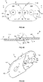
FIG.1A-1E : Ansichten einer gekröpften Seitenlasche gemäß einer ersten Ausführungsform in Seitenansicht von der dem Ketteninneren abgewandten Außenseite (FIG.1A ), im Längsschnitt gemäß Schnittlinie A-A (FIG.1B ), in vergrößertem Teilschnitt D (FIG.1D ), perspektivisch (FIG.1C ) und in einem vergrößerten Teilquerschnitt (FIG.1E ) gemäß Schnittlinie B-B ausFIG.1A ; -
FIG.2 : eine stark vergrößerte Kurvendarstellung der Übergangskurve des Querschnittsübergangs, der z.B. inFIG.1D und FIG.1E dargestellt ist; und -
FIG.3 : perspektivische Ansichten einer Innenlasche von der Außenseite (FIG.3A ) und einer Außenlasche von Innenseite (FIG. 3B ).
-
FIG.1A-1E : Views of a cranked side plate according to a first embodiment in a side view from the outside facing away from the inside of the chain (FIG.1A ), in longitudinal section according to section line AA (FIG.1B ), in enlarged partial section D (FIG.1D ), perspective (FIG.1C ) and in an enlarged partial cross-section (FIG.1E ) according to section line BBFIG.1A ; -
FIG.2 : a greatly enlarged curve representation of the transition curve of the cross-section transition, which is shown in e.gFIG.1D and FIG.1E is shown; and -
FIG.3 : Perspective views of an inner plate from the outside (FIG.3A ) and an outer flap from the inside (FIG. 3B ).
Der Mittelbereich 12 ist in Längsrichtung der Seitenlasche 10 beidseitig begrenzt durch eine etwa kreisbogenförmig um die jeweilige Schwenkachse verlaufende jeweilige Stirnfläche F11, F12, welche senkrecht zur Laschenhauptebene H steht (
Die Querschnittsübergänge Q1, Q2, Q3 gemäß der Übergangskurve C sind hinsichtlich Ermüdungsschäden, insbesondere kraftflussbedingter örtlicher Spannungskonzentrationen bzw. Spannungsspitzen im jeweiligen Bereich des Laschenkörpers der Seitenlasche 10 optimiert, da diese Bereiche stetigen Lastwechseln und/oder hohen Kräften standhalten müssen. Die Querschnittsübergänge Q1, Q2 bzw. Q3 erlauben eine Reduzierung der Materialstärke des Laschenkörpers bzw. eine weitergehende Reduzierung der Bodenwand der Anschlagtaschen 15A, 15B, oder bewirken bei gleichbleibender Materialstärke eine gesteigerte Betriebsfestigkeit (Festigkeit gegen wiederholende Lastwechsel) der angrenzenden Bereiche der Seitenlasche 10.The cross-sectional transitions Q1, Q2, Q3 according to the transition curve C are optimized with regard to fatigue damage, in particular local stress concentrations or stress peaks caused by the flow of force in the respective area of the link body of the
Die Überlappungsbereiche 11A, 11B und der Mittelbereich 12 weisen außerdem an weitere Bereichen, die hinsichtlich Spannungsspitzen unkritisch sind, Querschnittsübergänge auf, welche als gebrochene Kanten oder konventionell mit einem Radius entsprechend einem Viertelkreis gerundet sind. Konventionelle Radiusrundungen sind hier beispielhaft z.B. für die Übergänge der seitlichen Flächen F21, F22 der Überlappungsbereiche 11A, 11B zu den oberen und unteren Schmalseiten der Seitenlasche 10 (
Eine bevorzugte Übergangskurve C zur Konstruktion der Querschnittsübergänge Q1, Q2 bzw. Q3 ist in
Zur Optimierung des Kraftflusses günstigen Übergangskurven verlaufen zwischen zwei beidseitigen Äquidistanten bzw. Parallelkurven im Abstand d = 0,1 · A zum 45°-Kreissegment mit Z/A = ca. 2,5. Die Übergangskurve C hat in Grenzwertbetrachtung am Startpunkt PA eine Tangente die die erste Teilfläche F11, F21, F31 etwa in einem Winkel von ca. 45° +/- 5° schneidet, wobei eine Restkante an dieser Stelle zur Konstruktionsvereinfachung als unkritisch belassen werden kann.Favorable transition curves for optimizing the flow of forces run between two equidistant points on both sides or Parallel curves at a distance of d = 0.1 · A to the 45° circle segment with Z/A = approx. 2.5. Considering the limit value, the transition curve C has a tangent at the starting point PA which intersects the first partial surface F11, F21, F31 at an angle of approximately 45° +/- 5°, whereby a residual edge at this point can be left as uncritical to simplify the design.
Analog zum Prinzip aus
Im Gegensatz zu
Weiterhin zeigen
Hinsichtlich sonstiger an sich bekannter und z.T. hier nicht dargestellter Merkmale einer Energieführungskette wird abschließend zur Verkürzung auf
-
FIG.1A-1EFIG.1A-1E - 10 Seitenlasche (gekröpft)10 side flap (cranked)
- 11A, 11B Überlappungsbereiche11A, 11B Overlap areas
- 12 Mittelbereich12 mid-range
- 13 Gelenkaufnahme13 joint mount
- 14 Gelenkzapfen14 pivot pins
- 15A, 15B Anschlagtasche15A, 15B stop pocket
- 16A, 16B Anschlagvorsprung16A, 16B stopper projection
- F11, F21, F31 erste TeilflächeF11, F21, F31 first partial area
- F12, F22, F32 zweite TeilflächeF12, F22, F32 second patch
- H LaschenhauptebeneH tab main plane
- Q1, Q2, Q3 QuerschnittsübergangQ1, Q2, Q3 cross-section transition
-
FIG.2FIG.2 - C ÜbergangskurveC transition curve
- PA Startpunkt (Übergangskurve)PA starting point (transition curve)
- PZ Endpunkt (Übergangskurve)PZ end point (transition curve)
- R Radius (45°-Kreissegment)R radius (45° circle segment)
-
FIG.3A-3BFIG.3A-3B - 30A Innenlasche30A inner plate
- 30B Außenlasche30B outer plate
- 31A, 31B Überlappungsbereiche (Innenlasche)31A, 31B Overlap areas (inner plate)
- 31C, 31D Überlappungsbereiche (Außenlasche)31C, 31D Overlap areas (outer flap)
- 32A, 32B Mittelbereich32A, 32B mid-section
- 33 Gelenkaufnahme33 joint mount
- 34 Gelenkzapfen34 pivot pins
- 35A, 35B, 35C, 35D Anschlagtasche35A, 35B, 35C, 35D stop pocket
- 36A, 36B, 36C, 36D Anschlagvorsprung36A, 36B, 36C, 36D stop projection
- 37A, 37B Materialaussparung37A, 37B material recess
- F11, F21 erste TeilflächeF11, F21 first partial area
- F12, F22 zweite TeilflächeF12, F22 second partial surface
- Q1, Q2, Q4, Q5 QuerschnittsübergangQ1, Q2, Q4, Q5 cross section transition
Claims (14)
- A side plate (10; 30A, 30B) for an energy guide chain for guiding lines using chain links which comprise two opposing side plates which are connected together via at least one crosspiece, wherein the side plate (10; 30A, 30B) has a one-piece plate body of plastics material with two overlap regions (11A, 11B; 31A-31D), in each case for swivelable connection to a corresponding overlap region of an adjoining plate, and a central region (12; 32A, 32B) between the overlap regions; and wherein the overlap regions and the central region have a number of cross-sectional transitions, in each case between two outer subsurfaces, at least one cross-sectional transition of which between a first subsurface (F11, F21, F31) of the plate body and a second subsurface (F12, F22, F32) extending at an angle, in particular an angle 90°, to said first subsurface, is rounded or chamfered (Q1-Q5); wherein the at least one cross-sectional transition (Q1-Q5) is delimited by an envelope transition curve (C) with a course such that, for a starting point (PA) of the transition curve (C) at the first subsurface (F11, F21, F31), which is located at a distance A from the intersection curve of the first subsurface with second subsurface, the endpoint (PZ) of the transition curve (C) at the second subsurface (F12, F22, F32) is located at a distance Z from said intersection curve, with 1.7 · A ≤ Z ≤ 4.0 · A, in particular with 2.3 · A ≤ Z ≤ 3.4 · A, and such that the cross-sectional area of the cross-sectional transition (Q1-Q5) decreases continuously along the transition curve (C) from the starting point (PA) to the endpoint (PZ).
- The side plate according to Claim 1, characterized in that the transition curve (C) corresponds to a smooth or stepless and strictly monotonically falling curve.
- The side plate according to one of Claims 1 to 2, characterized in that the first subsurface (F11, F21, F31) is located perpendicular to the main plane of the side plate and the second subsurface is located parallel (F12, F22, F32) to the main plane (H) of the plate body.
- The side plate according to Claim 3, characterized in that the first subsurface with the starting point (PA) is located on the central region (12; 32A, 32B) and the second subsurface with the endpoint (PZ) on an overlap region (11A, 11B; 31A-31D).
- The side plate according to Claim 3, characterized in that the first subsurface (F31) with the starting point (PA) corresponds to a stop surface with a limit stop effect of a stop recess (15A, 15B) in an overlap region and the second subsurface (F32) with the endpoint (PZ) corresponds to a bottom wall which closes the stop recess (15A, 15B) on one side.
- The side plate according to Claim 3, characterized in that the first subsurface with the starting point is located on a swivel pin in the overlap region and the second subsurface with the endpoint is located on a sidewall region from which the swivel pin protrudes.
- The side plate according to one of Claims 1 to 3, characterized in that the transition curve (C) defines the cross-sectional transition (Q5) from an outer surface of the plate body into a material recess (37A, 37B).
- The side plate according to one of the preceding claims, in particular Claim 2, characterized in that the course of the transition curve (C) is selected such that the endpoint is located at a distance Z from the intersection curve with 2.2 · A ≤ Z ≤ 2.6 · A, and the course in particular corresponds to a 45° circle segment of a circle which tangentially touches the second subsurface (F12, F22, F32) in the endpoint (PZ).
- The side plate according to one of the preceding claims, characterized in that the angle between the first outer subsurface (F11, F21, F31) and the second outer subsurface (F12, F22, F32) of the plate body amounts to a constant 90° along the cross-sectional transition, and- in that the course of the transition curve (C) in the initial portion at the starting point (PA) has a tangent which forms an angle of approx. 45° ±5° with the first subsurface (F11, F21, F31); and/or- in that the course of the transition curve in the end portion at the endpoint (PZ) has a tangent which is substantially parallel to the second subsurface or continuously merges into it.
- The side plate according to one of the preceding claims, characterized in that the at least one cross-sectional transition (Q1-Q5) is asymmetric to the bisector of the first and second surfaces and/or is produced in one piece with the plate body from a thermoplastic, in particular by the injection molding method.
- The side plate according to one of the preceding claims, characterized in that the second subsurface (F12, F22, F32) with the endpoint (PZ) of the transition curve (C) is provided at a region of the plate body which is intended to transmit at least tensile force.
- The side plate according to one of the preceding claims, characterized in that it takes the form of an inner plate (30A), an outer plate (30B) or an offset plate (10).
- A chain link of an energy guide chain having two opposing side plates (10; 30A, 30B) according to one of the preceding claims.
- An energy guide chain comprising two strings of plates which in each case consist of side plates (10; 30A, 30B) according to one of preceding claims 1 to 12 which are joined together swivelably in the longitudinal direction.
Applications Claiming Priority (2)
| Application Number | Priority Date | Filing Date | Title |
|---|---|---|---|
| DE202019100465.7U DE202019100465U1 (en) | 2019-01-25 | 2019-01-25 | Operationally designed side flap for an energy chain |
| PCT/EP2020/051520 WO2020152221A1 (en) | 2019-01-25 | 2020-01-22 | Operationally stable side plate for an energy chain |
Publications (2)
| Publication Number | Publication Date |
|---|---|
| EP3894720A1 EP3894720A1 (en) | 2021-10-20 |
| EP3894720B1 true EP3894720B1 (en) | 2022-06-08 |
Family
ID=66816844
Family Applications (1)
| Application Number | Title | Priority Date | Filing Date |
|---|---|---|---|
| EP20704781.2A Active EP3894720B1 (en) | 2019-01-25 | 2020-01-22 | Operationally stable side plate for an energy chain |
Country Status (12)
| Country | Link |
|---|---|
| US (1) | US20220082184A1 (en) |
| EP (1) | EP3894720B1 (en) |
| JP (1) | JP7464610B2 (en) |
| KR (1) | KR20210119483A (en) |
| CN (1) | CN113795686B (en) |
| BR (1) | BR112021013937A2 (en) |
| CA (1) | CA3127646C (en) |
| DE (1) | DE202019100465U1 (en) |
| ES (1) | ES2924310T3 (en) |
| PL (1) | PL3894720T3 (en) |
| SG (1) | SG11202108117TA (en) |
| WO (1) | WO2020152221A1 (en) |
Family Cites Families (15)
| Publication number | Priority date | Publication date | Assignee | Title |
|---|---|---|---|---|
| DE2126255A1 (en) * | 1971-05-26 | 1972-12-07 | Gebr Hennig GmbH, 8045 Ismamng | Link chain |
| DE2255283C3 (en) * | 1972-11-11 | 1975-06-05 | Kabelschlepp Gmbh, 5900 Siegen | Energy chain |
| IT1121572B (en) * | 1979-06-08 | 1986-04-02 | Mauri Giovanni | MONOBLOCK ELEMENT CABLE CHAIN |
| DE3139735A1 (en) * | 1981-10-06 | 1983-04-21 | Ernst 4000 Düsseldorf Klein | Cable routing chain |
| DE3531066A1 (en) | 1985-08-30 | 1987-03-12 | Igus Gmbh | ENERGY FEED CHAIN |
| DE4325259C2 (en) | 1993-07-28 | 1995-07-20 | Igus Gmbh | Energy chain |
| US6190277B1 (en) * | 1997-07-10 | 2001-02-20 | Igus Spritzgussteile für die Industrie GmbH | Energy transmission chain |
| DE20002820U1 (en) | 2000-02-16 | 2000-05-25 | Igus Gmbh | Energy chain |
| US6978595B2 (en) | 2002-02-05 | 2005-12-27 | Delphi Technologies, Inc. | Chain links and cable carrier chains containing same |
| DE10339168A1 (en) * | 2003-08-21 | 2005-04-28 | Kabelschlepp Gmbh | Chain link for an energy chain and energy chain |
| DE102008060466A1 (en) * | 2008-12-05 | 2010-06-10 | Kabelschlepp Gmbh | Chain link for energy transmission chain for guiding cables and hoses between stationary and movable connection points, has transverse bar consisting of plastic that is guided by die in continuous manufacturing process of transverse bar |
| DE102012006446B4 (en) * | 2012-03-30 | 2020-06-04 | Tsubaki Kabelschlepp GmbH | Metallic link of a chain link of an energy chain |
| DE202012003903U1 (en) * | 2012-04-19 | 2012-05-25 | Igus Gmbh | Energy guiding chain with rollers |
| DE202014101366U1 (en) * | 2014-03-24 | 2014-03-28 | Igus Gmbh | Cable guide device with one-piece joint, corresponding chain link and hinge |
| DE202014104075U1 (en) * | 2014-09-01 | 2014-09-09 | Igus Gmbh | Cable guide |
-
2019
- 2019-01-25 DE DE202019100465.7U patent/DE202019100465U1/en active Active
-
2020
- 2020-01-22 WO PCT/EP2020/051520 patent/WO2020152221A1/en unknown
- 2020-01-22 CN CN202080015388.6A patent/CN113795686B/en active Active
- 2020-01-22 PL PL20704781.2T patent/PL3894720T3/en unknown
- 2020-01-22 ES ES20704781T patent/ES2924310T3/en active Active
- 2020-01-22 BR BR112021013937-0A patent/BR112021013937A2/en unknown
- 2020-01-22 EP EP20704781.2A patent/EP3894720B1/en active Active
- 2020-01-22 CA CA3127646A patent/CA3127646C/en active Active
- 2020-01-22 SG SG11202108117TA patent/SG11202108117TA/en unknown
- 2020-01-22 US US17/310,178 patent/US20220082184A1/en active Pending
- 2020-01-22 JP JP2021542383A patent/JP7464610B2/en active Active
- 2020-01-22 KR KR1020217026899A patent/KR20210119483A/en unknown
Also Published As
| Publication number | Publication date |
|---|---|
| EP3894720A1 (en) | 2021-10-20 |
| US20220082184A1 (en) | 2022-03-17 |
| JP2022519187A (en) | 2022-03-22 |
| WO2020152221A1 (en) | 2020-07-30 |
| CN113795686B (en) | 2023-06-23 |
| KR20210119483A (en) | 2021-10-05 |
| CA3127646A1 (en) | 2020-07-30 |
| BR112021013937A2 (en) | 2021-09-21 |
| DE202019100465U1 (en) | 2019-05-28 |
| JP7464610B2 (en) | 2024-04-09 |
| SG11202108117TA (en) | 2021-08-30 |
| PL3894720T3 (en) | 2022-11-14 |
| CN113795686A (en) | 2021-12-14 |
| ES2924310T3 (en) | 2022-10-05 |
| CA3127646C (en) | 2024-05-14 |
Similar Documents
| Publication | Publication Date | Title |
|---|---|---|
| EP1975093B1 (en) | Side-flexing conveyor chain with interior and exterior chain links | |
| EP1503107B2 (en) | Articulation device for energy carriers supporting chain | |
| EP1256153B1 (en) | Energy guiding chain | |
| EP0803032B1 (en) | Energy management chain | |
| EP2694841B1 (en) | Cable carrier chain with deformable joint elements | |
| EP1283381B1 (en) | Supporting chain for energy carriers and chain link | |
| DE19710489A1 (en) | Foldable protective element for cables | |
| DE202006009482U1 (en) | Joint element for energy supply chain | |
| EP3789635B1 (en) | Gearwheel | |
| DE102007018501A1 (en) | Latch chain comprises multiple chains and always forms chain link, which are connected with joint having adjacent chain link, where latch chain has damping latches, which connects two adjacent chain link elastically with each other | |
| DE19647322A1 (en) | Chain link made of different materials and process for its production | |
| WO2005108820A1 (en) | Chain link for a power transmission chain, and power transmission chain having an expanded useful cross section | |
| WO2013174666A1 (en) | Belt end body or belt segment end body | |
| DE4325259C2 (en) | Energy chain | |
| DE202017101466U1 (en) | With a chain drive operable back rigid push chain | |
| EP1757838B1 (en) | Stiff back drive chain | |
| EP3069423B1 (en) | Line guide | |
| EP0165955A1 (en) | Rim for motor vehicles or the like | |
| DE102005061775A1 (en) | Chain link with a locking device | |
| EP3894720B1 (en) | Operationally stable side plate for an energy chain | |
| DE102016111542B4 (en) | Linear chain with standardized end piece | |
| EP3115642A1 (en) | Belt or belt segment | |
| DE202012011094U1 (en) | Roller or leaf chain with at least one attachment | |
| EP3568604B1 (en) | Bellows comprising at least one internal groove | |
| EP1999396B1 (en) | Non-warping chain link |
Legal Events
| Date | Code | Title | Description |
|---|---|---|---|
| STAA | Information on the status of an ep patent application or granted ep patent |
Free format text: STATUS: UNKNOWN |
|
| STAA | Information on the status of an ep patent application or granted ep patent |
Free format text: STATUS: THE INTERNATIONAL PUBLICATION HAS BEEN MADE |
|
| PUAI | Public reference made under article 153(3) epc to a published international application that has entered the european phase |
Free format text: ORIGINAL CODE: 0009012 |
|
| STAA | Information on the status of an ep patent application or granted ep patent |
Free format text: STATUS: REQUEST FOR EXAMINATION WAS MADE |
|
| 17P | Request for examination filed |
Effective date: 20210711 |
|
| AK | Designated contracting states |
Kind code of ref document: A1 Designated state(s): AL AT BE BG CH CY CZ DE DK EE ES FI FR GB GR HR HU IE IS IT LI LT LU LV MC MK MT NL NO PL PT RO RS SE SI SK SM TR |
|
| GRAP | Despatch of communication of intention to grant a patent |
Free format text: ORIGINAL CODE: EPIDOSNIGR1 |
|
| STAA | Information on the status of an ep patent application or granted ep patent |
Free format text: STATUS: GRANT OF PATENT IS INTENDED |
|
| INTG | Intention to grant announced |
Effective date: 20220127 |
|
| GRAS | Grant fee paid |
Free format text: ORIGINAL CODE: EPIDOSNIGR3 |
|
| DAV | Request for validation of the european patent (deleted) | ||
| DAX | Request for extension of the european patent (deleted) | ||
| GRAA | (expected) grant |
Free format text: ORIGINAL CODE: 0009210 |
|
| STAA | Information on the status of an ep patent application or granted ep patent |
Free format text: STATUS: THE PATENT HAS BEEN GRANTED |
|
| AK | Designated contracting states |
Kind code of ref document: B1 Designated state(s): AL AT BE BG CH CY CZ DE DK EE ES FI FR GB GR HR HU IE IS IT LI LT LU LV MC MK MT NL NO PL PT RO RS SE SI SK SM TR |
|
| REG | Reference to a national code |
Ref country code: AT Ref legal event code: REF Ref document number: 1497139 Country of ref document: AT Kind code of ref document: T Effective date: 20220615 Ref country code: CH Ref legal event code: EP |
|
| REG | Reference to a national code |
Ref country code: DE Ref legal event code: R096 Ref document number: 502020001213 Country of ref document: DE |
|
| REG | Reference to a national code |
Ref country code: IE Ref legal event code: FG4D Free format text: LANGUAGE OF EP DOCUMENT: GERMAN |
|
| REG | Reference to a national code |
Ref country code: NL Ref legal event code: FP |
|
| REG | Reference to a national code |
Ref country code: LT Ref legal event code: MG9D |
|
| REG | Reference to a national code |
Ref country code: ES Ref legal event code: FG2A Ref document number: 2924310 Country of ref document: ES Kind code of ref document: T3 Effective date: 20221005 |
|
| PG25 | Lapsed in a contracting state [announced via postgrant information from national office to epo] |
Ref country code: SE Free format text: LAPSE BECAUSE OF FAILURE TO SUBMIT A TRANSLATION OF THE DESCRIPTION OR TO PAY THE FEE WITHIN THE PRESCRIBED TIME-LIMIT Effective date: 20220608 Ref country code: NO Free format text: LAPSE BECAUSE OF FAILURE TO SUBMIT A TRANSLATION OF THE DESCRIPTION OR TO PAY THE FEE WITHIN THE PRESCRIBED TIME-LIMIT Effective date: 20220908 Ref country code: LT Free format text: LAPSE BECAUSE OF FAILURE TO SUBMIT A TRANSLATION OF THE DESCRIPTION OR TO PAY THE FEE WITHIN THE PRESCRIBED TIME-LIMIT Effective date: 20220608 Ref country code: HR Free format text: LAPSE BECAUSE OF FAILURE TO SUBMIT A TRANSLATION OF THE DESCRIPTION OR TO PAY THE FEE WITHIN THE PRESCRIBED TIME-LIMIT Effective date: 20220608 Ref country code: GR Free format text: LAPSE BECAUSE OF FAILURE TO SUBMIT A TRANSLATION OF THE DESCRIPTION OR TO PAY THE FEE WITHIN THE PRESCRIBED TIME-LIMIT Effective date: 20220909 Ref country code: FI Free format text: LAPSE BECAUSE OF FAILURE TO SUBMIT A TRANSLATION OF THE DESCRIPTION OR TO PAY THE FEE WITHIN THE PRESCRIBED TIME-LIMIT Effective date: 20220608 Ref country code: BG Free format text: LAPSE BECAUSE OF FAILURE TO SUBMIT A TRANSLATION OF THE DESCRIPTION OR TO PAY THE FEE WITHIN THE PRESCRIBED TIME-LIMIT Effective date: 20220908 |
|
| PG25 | Lapsed in a contracting state [announced via postgrant information from national office to epo] |
Ref country code: RS Free format text: LAPSE BECAUSE OF FAILURE TO SUBMIT A TRANSLATION OF THE DESCRIPTION OR TO PAY THE FEE WITHIN THE PRESCRIBED TIME-LIMIT Effective date: 20220608 Ref country code: LV Free format text: LAPSE BECAUSE OF FAILURE TO SUBMIT A TRANSLATION OF THE DESCRIPTION OR TO PAY THE FEE WITHIN THE PRESCRIBED TIME-LIMIT Effective date: 20220608 |
|
| PG25 | Lapsed in a contracting state [announced via postgrant information from national office to epo] |
Ref country code: SM Free format text: LAPSE BECAUSE OF FAILURE TO SUBMIT A TRANSLATION OF THE DESCRIPTION OR TO PAY THE FEE WITHIN THE PRESCRIBED TIME-LIMIT Effective date: 20220608 Ref country code: SK Free format text: LAPSE BECAUSE OF FAILURE TO SUBMIT A TRANSLATION OF THE DESCRIPTION OR TO PAY THE FEE WITHIN THE PRESCRIBED TIME-LIMIT Effective date: 20220608 Ref country code: RO Free format text: LAPSE BECAUSE OF FAILURE TO SUBMIT A TRANSLATION OF THE DESCRIPTION OR TO PAY THE FEE WITHIN THE PRESCRIBED TIME-LIMIT Effective date: 20220608 Ref country code: PT Free format text: LAPSE BECAUSE OF FAILURE TO SUBMIT A TRANSLATION OF THE DESCRIPTION OR TO PAY THE FEE WITHIN THE PRESCRIBED TIME-LIMIT Effective date: 20221010 Ref country code: EE Free format text: LAPSE BECAUSE OF FAILURE TO SUBMIT A TRANSLATION OF THE DESCRIPTION OR TO PAY THE FEE WITHIN THE PRESCRIBED TIME-LIMIT Effective date: 20220608 Ref country code: CZ Free format text: LAPSE BECAUSE OF FAILURE TO SUBMIT A TRANSLATION OF THE DESCRIPTION OR TO PAY THE FEE WITHIN THE PRESCRIBED TIME-LIMIT Effective date: 20220608 |
|
| PG25 | Lapsed in a contracting state [announced via postgrant information from national office to epo] |
Ref country code: IS Free format text: LAPSE BECAUSE OF FAILURE TO SUBMIT A TRANSLATION OF THE DESCRIPTION OR TO PAY THE FEE WITHIN THE PRESCRIBED TIME-LIMIT Effective date: 20221008 |
|
| REG | Reference to a national code |
Ref country code: DE Ref legal event code: R097 Ref document number: 502020001213 Country of ref document: DE |
|
| PG25 | Lapsed in a contracting state [announced via postgrant information from national office to epo] |
Ref country code: AL Free format text: LAPSE BECAUSE OF FAILURE TO SUBMIT A TRANSLATION OF THE DESCRIPTION OR TO PAY THE FEE WITHIN THE PRESCRIBED TIME-LIMIT Effective date: 20220608 |
|
| PLBE | No opposition filed within time limit |
Free format text: ORIGINAL CODE: 0009261 |
|
| STAA | Information on the status of an ep patent application or granted ep patent |
Free format text: STATUS: NO OPPOSITION FILED WITHIN TIME LIMIT |
|
| PG25 | Lapsed in a contracting state [announced via postgrant information from national office to epo] |
Ref country code: DK Free format text: LAPSE BECAUSE OF FAILURE TO SUBMIT A TRANSLATION OF THE DESCRIPTION OR TO PAY THE FEE WITHIN THE PRESCRIBED TIME-LIMIT Effective date: 20220608 |
|
| PGFP | Annual fee paid to national office [announced via postgrant information from national office to epo] |
Ref country code: FR Payment date: 20230123 Year of fee payment: 4 |
|
| 26N | No opposition filed |
Effective date: 20230310 |
|
| PGFP | Annual fee paid to national office [announced via postgrant information from national office to epo] |
Ref country code: PL Payment date: 20230111 Year of fee payment: 4 Ref country code: IT Payment date: 20230131 Year of fee payment: 4 |
|
| P01 | Opt-out of the competence of the unified patent court (upc) registered |
Effective date: 20230526 |
|
| PG25 | Lapsed in a contracting state [announced via postgrant information from national office to epo] |
Ref country code: LU Free format text: LAPSE BECAUSE OF NON-PAYMENT OF DUE FEES Effective date: 20230122 |
|
| REG | Reference to a national code |
Ref country code: BE Ref legal event code: MM Effective date: 20230131 |
|
| PG25 | Lapsed in a contracting state [announced via postgrant information from national office to epo] |
Ref country code: BE Free format text: LAPSE BECAUSE OF NON-PAYMENT OF DUE FEES Effective date: 20230131 |
|
| PG25 | Lapsed in a contracting state [announced via postgrant information from national office to epo] |
Ref country code: IE Free format text: LAPSE BECAUSE OF NON-PAYMENT OF DUE FEES Effective date: 20230122 |
|
| PGFP | Annual fee paid to national office [announced via postgrant information from national office to epo] |
Ref country code: NL Payment date: 20240123 Year of fee payment: 5 |
|
| PGFP | Annual fee paid to national office [announced via postgrant information from national office to epo] |
Ref country code: ES Payment date: 20240216 Year of fee payment: 5 |
|
| PGFP | Annual fee paid to national office [announced via postgrant information from national office to epo] |
Ref country code: DE Payment date: 20240325 Year of fee payment: 5 Ref country code: GB Payment date: 20240124 Year of fee payment: 5 Ref country code: CH Payment date: 20240202 Year of fee payment: 5 |