EP3894718B1 - Kolbenstangenende für einen linearantrieb, kolbenanordnung und dichtungsverfahren für ein kolbenstangenende - Google Patents
Kolbenstangenende für einen linearantrieb, kolbenanordnung und dichtungsverfahren für ein kolbenstangenende Download PDFInfo
- Publication number
- EP3894718B1 EP3894718B1 EP19828349.1A EP19828349A EP3894718B1 EP 3894718 B1 EP3894718 B1 EP 3894718B1 EP 19828349 A EP19828349 A EP 19828349A EP 3894718 B1 EP3894718 B1 EP 3894718B1
- Authority
- EP
- European Patent Office
- Prior art keywords
- piston rod
- rod end
- housing
- connector
- insert
- Prior art date
- Legal status (The legal status is an assumption and is not a legal conclusion. Google has not performed a legal analysis and makes no representation as to the accuracy of the status listed.)
- Active
Links
Images


Classifications
-
- F—MECHANICAL ENGINEERING; LIGHTING; HEATING; WEAPONS; BLASTING
- F16—ENGINEERING ELEMENTS AND UNITS; GENERAL MEASURES FOR PRODUCING AND MAINTAINING EFFECTIVE FUNCTIONING OF MACHINES OR INSTALLATIONS; THERMAL INSULATION IN GENERAL
- F16F—SPRINGS; SHOCK-ABSORBERS; MEANS FOR DAMPING VIBRATION
- F16F15/00—Suppression of vibrations in systems; Means or arrangements for avoiding or reducing out-of-balance forces, e.g. due to motion
- F16F15/02—Suppression of vibrations of non-rotating, e.g. reciprocating systems; Suppression of vibrations of rotating systems by use of members not moving with the rotating systems
- F16F15/04—Suppression of vibrations of non-rotating, e.g. reciprocating systems; Suppression of vibrations of rotating systems by use of members not moving with the rotating systems using elastic means
- F16F15/06—Suppression of vibrations of non-rotating, e.g. reciprocating systems; Suppression of vibrations of rotating systems by use of members not moving with the rotating systems using elastic means with metal springs
- F16F15/067—Suppression of vibrations of non-rotating, e.g. reciprocating systems; Suppression of vibrations of rotating systems by use of members not moving with the rotating systems using elastic means with metal springs using only wound springs
-
- B—PERFORMING OPERATIONS; TRANSPORTING
- B61—RAILWAYS
- B61G—COUPLINGS; DRAUGHT AND BUFFING APPLIANCES
- B61G11/00—Buffers
- B61G11/14—Buffers absorbing shocks by mechanical friction action; Combinations of mechanical shock-absorbers and springs
-
- B—PERFORMING OPERATIONS; TRANSPORTING
- B61—RAILWAYS
- B61G—COUPLINGS; DRAUGHT AND BUFFING APPLIANCES
- B61G11/00—Buffers
- B61G11/12—Buffers with fluid springs or shock-absorbers; Combinations thereof
-
- B—PERFORMING OPERATIONS; TRANSPORTING
- B61—RAILWAYS
- B61G—COUPLINGS; DRAUGHT AND BUFFING APPLIANCES
- B61G11/00—Buffers
- B61G11/02—Buffers with metal springs
- B61G11/04—Buffers with metal springs with helical springs
-
- F—MECHANICAL ENGINEERING; LIGHTING; HEATING; WEAPONS; BLASTING
- F16—ENGINEERING ELEMENTS AND UNITS; GENERAL MEASURES FOR PRODUCING AND MAINTAINING EFFECTIVE FUNCTIONING OF MACHINES OR INSTALLATIONS; THERMAL INSULATION IN GENERAL
- F16F—SPRINGS; SHOCK-ABSORBERS; MEANS FOR DAMPING VIBRATION
- F16F1/00—Springs
- F16F1/02—Springs made of steel or other material having low internal friction; Wound, torsion, leaf, cup, ring or the like springs, the material of the spring not being relevant
- F16F1/04—Wound springs
- F16F1/12—Attachments or mountings
- F16F1/128—Attachments or mountings with motion-limiting means, e.g. with a full-length guide element or ball joint connections; with protective outer cover
-
- B—PERFORMING OPERATIONS; TRANSPORTING
- B60—VEHICLES IN GENERAL
- B60D—VEHICLE CONNECTIONS
- B60D1/00—Traction couplings; Hitches; Draw-gear; Towing devices
- B60D1/14—Draw-gear or towing devices characterised by their type
-
- B—PERFORMING OPERATIONS; TRANSPORTING
- B60—VEHICLES IN GENERAL
- B60D—VEHICLE CONNECTIONS
- B60D1/00—Traction couplings; Hitches; Draw-gear; Towing devices
- B60D1/48—Traction couplings; Hitches; Draw-gear; Towing devices characterised by the mounting
- B60D1/481—Traction couplings; Hitches; Draw-gear; Towing devices characterised by the mounting adapted for being mounted to the front and back of trailers, carts, trolleys, or the like to form a train
-
- B—PERFORMING OPERATIONS; TRANSPORTING
- B61—RAILWAYS
- B61G—COUPLINGS; DRAUGHT AND BUFFING APPLIANCES
- B61G9/00—Draw-gear
- B61G9/04—Draw-gear combined with buffing appliances
- B61G9/045—Draw-gear combined with buffing appliances with only metal springs
-
- B—PERFORMING OPERATIONS; TRANSPORTING
- B61—RAILWAYS
- B61G—COUPLINGS; DRAUGHT AND BUFFING APPLIANCES
- B61G9/00—Draw-gear
- B61G9/20—Details; Accessories
-
- F—MECHANICAL ENGINEERING; LIGHTING; HEATING; WEAPONS; BLASTING
- F16—ENGINEERING ELEMENTS AND UNITS; GENERAL MEASURES FOR PRODUCING AND MAINTAINING EFFECTIVE FUNCTIONING OF MACHINES OR INSTALLATIONS; THERMAL INSULATION IN GENERAL
- F16F—SPRINGS; SHOCK-ABSORBERS; MEANS FOR DAMPING VIBRATION
- F16F2230/00—Purpose; Design features
- F16F2230/30—Sealing arrangements
-
- F—MECHANICAL ENGINEERING; LIGHTING; HEATING; WEAPONS; BLASTING
- F16—ENGINEERING ELEMENTS AND UNITS; GENERAL MEASURES FOR PRODUCING AND MAINTAINING EFFECTIVE FUNCTIONING OF MACHINES OR INSTALLATIONS; THERMAL INSULATION IN GENERAL
- F16F—SPRINGS; SHOCK-ABSORBERS; MEANS FOR DAMPING VIBRATION
- F16F2230/00—Purpose; Design features
- F16F2230/36—Holes, slots or the like
Definitions
- the present invention relates to a piston rod end for absorbing forces on a linear actuator in a train coupler and to a piston assembly comprising a linear actuator and such a piston rod end.
- the invention also relates to a method for sealing a piston rod end to prevent intrusion of dirt.
- Train couplers generally comprise linear actuators.
- Pneumatic actuators are advantageous since they are robust and able to withstand linear forces on the actuator during normal operation of the train coupler due to the pneumatic system that acts as a damper.
- electric actuators are used instead.
- WO02017201535A1 discloses a railcar end unit that is operable to be mounted in a center sill between buff and draft sill stops.
- the buff and draft end bodies are configured to be shiftably mounted relative to the center sill to engage the respective sill stops and to shift axially relative to one another along a unit axis.
- the end unit includes a buff spring pack operably mounted between the end bodies and compressible along the unit axis from a neutral condition to a compressed condition.
- the object of the present invention is to eliminate or at least to minimize the problems mentioned above. This is achieved through a piston rod end and a piston assembly comprising such a piston rod end according to the appended independent claim.
- a piston rod end and a piston assembly comprising such a piston rod end according to the appended independent claim.
- the operation of the piston rod end can be improved by preventing dust and dirt from entering an internal cavity of the piston rod end.
- the piston rod end for absorbing forces on a linear actuator in a train coupler comprises
- the cavity is essentially cylindrical and the insert is preferably also essentially cylindrical and has a diameter that is less than or equal to a diameter of the cavity.
- the transversal element comprises at least one screw, bolt or pin, preferably a socket head screw.
- the transversal element can be mounted after the insert is inserted into the housing and provide a strong and reliable stop for the movement of the insert in relation to the housing by contacting ends of the slot.
- the first connector comprises a rotational stop for preventing rotation of the piston rod end in relation to the first connector, said rotational stop preferably being a jam nut that is joined to the first connector by an external thread on the first connector.
- the insert comprises a sealing ring arranged on a circumference of the insert for preventing intrusion of dirt or dust into the cavity.
- the spring is able to contract and extend without being hindered by undesired particles entering the cavity, and the lifetime of the piston rod end is extended.
- the housing comprises an external sealing arranged on an outer circumference for preventing intrusion of dirt or dust into the cavity.
- the slot is in the housing this protects the cavity further from dirt or dust so ensure smooth operation of the spring and extend the lifetime of the piston rod end.
- the piston rod end comprises an additional fastening device that is placed diametrically opposite from the fastening device on the housing and insert.
- the insert comprises the transversal element and the housing comprises the slot, and wherein the transversal element is arranged to protrude into the slot but not extend beyond an outer surface of the housing.
- the movement of the transversal element is not hindered by the possible presence of the external sealing.
- the piston rod end can be rendered especially cost effective and robust.
- the invention also comprises a piston assembly for a train coupler comprising a linear actuator and a piston rod end according to the invention, the piston rod end being mounted on the linear actuator by the first connector on the piston rod end being joined to an actuator connector on a first end of the linear actuator, preferably by screwing an outer thread on one of the first connector and actuator connector onto an inner thread of the other.
- Linear actuators are often designed to extend from a compressed state to a fully extended state (full stroke) without intermediate stroke lengths, and a particular advantage of providing the piston rod end in the piston assembly is that the piston rod end serves to take up additional stroke so that desired tolerances are not exceeded.
- the linear actuator comprises an electric motor that is arranged to increase or decrease an actuator length, said motor being arranged to operate with a maximum motor force and the spring of the piston rod end further having a spring force, said spring force being smaller than or equal to the maximum motor force.
- the piston rod end will absorb vibrations or small longitudinal movements when mounted in a train coupler to protect the linear actuator.
- a second piston rod end according to the invention, the second piston rod end being mounted on a second end of the linear actuator.
- the present invention also comprises a sealing method for sealing the piston rod end of the present invention to prevent intrusion of dirt or dust into the cavity.
- the sealing method comprises
- a secure seal is provided that ensures the operation of the spring and insert without risking obstruction or wear because of substances or particles that could otherwise intrude through an opening in the housing.
- At least one adhesive device is placed between the housing and the sealing tube before heating. Thereby, slippage of the sealing tube in relation to the housing is prevented.
- At least two portions of the sealing tube are heated, said at least two portions being distributed around a circumference of the sealing tube.
- WO2017201535A1 discloses a railcar end unit but is not a piston rod end and is also not configured to reduce maintenance and increase lifespan of electrical actuators.
- Fig. 1a-1b discloses a linear actuator 100 according to the prior art, having an actuator body 110 or piston, a first linear actuator connector 120 also known as a back fixture and a second linear actuator connector 130 for mounting the linear actuator 100 in a train coupler, preferably by means of through holes 140 into which fastening elements can be inserted for fixating the linear actuator.
- the linear actuator 100 is able to extend and contract between an extended state and a compressed state by means of an electrical motor (not shown) as is well known within the art.
- the second linear actuator connector 130 is mounted on the linear actuator body 110 by fastening to an actuator connector 150, preferably by screwing but commonly also by other means.
- the second linear actuator connector 130 is generally a stiff part and cannot be compressed; it therefore acts as an extension of the actuator body 110.
- Fig. 2a-2b discloses a piston assembly 10 according to a preferred embodiment of the present invention, comprising a piston rod end 1 according to the invention that is mounted on a linear actuator 100 by a first connector 6 being joined to an actuator connector 150 at a first end of the linear actuator 100, preferably by screwing an outer thread on one of the first connector 6 and actuator connector 150 onto an inner thread of the other.
- the piston assembly 10 also comprises a second piston rod end 1 that is mounted on a second end of the linear actuator 100.
- Linear actuators such as the linear actuator 100 generally have a tolerance (typically tolerances on the built-in dimensions as well as on the stroke length depending on the manufacturer) that makes it difficult to predict an actual piston length when the linear actuator is extended to full stroke.
- a tolerance typically tolerances on the built-in dimensions as well as on the stroke length depending on the manufacturer
- the piston rod end 1 will be able to compensate for this so that the linear actuator 100 can be extended to a desired length regardless of the tolerance.
- the piston rod end 1 comprises a housing 2 and an insert 3 that is mounted in the housing 2 together with a spring 5 (see Fig 3 ) so that a length of the piston rod end 1 can vary between a compressed state and an extended state, as will be described in more detail below.
- a fastening device 4 connects the housing 2 and the insert 3 and creates a play that allows the insert 3 and the housing 2 to move in relation to each other.
- a second connector 7 is also provided on the piston rod end 1 and serves the same function as the second linear actuator connector 130 described above with reference to the prior art.
- the piston rod end 1 is connectable to the linear actuator 100 to form the piston assembly 10 and allows for a total length of the linear actuator 100 and piston rod end 1 to vary within predetermined allowances so that forces on the linear actuator 100 during operation of the train coupler can be absorbed by the piston rod end 1 and damages to the linear actuator can be prevented.
- Fig. 3 discloses the piston rod end 1 in more detail, showing the housing 2 with a housing wall 22.
- the housing 2 encloses a cavity 23 that extends in a longitudinal direction in the housing 2 and that has a bottom surface 24.
- the housing 2 also comprises a rotational stop 21 that is provided to prevent undesired rotation of the piston rod end 1 in relation to the linear actuator 100 when mounted.
- the rotational stop 21 is a jam nut that is joined to the first connector 6 by an external thread on the first connector 6.
- the rotational stop 21 also has the function of adapting a length of the piston rod end 1 at mounting, especially when threads are provided on the piston rod end 1 and linear actuator 100. The piston rod end 1 is thus screwed onto the linear actuator 100 or vice versa until a desired total length of the piston assembly 10 has been reached and the rotational stop 21 is then used to prevent further rotational movement of one against the other.
- the piston rod end 1 also comprises an insert 3 that is at least partly inserted into the cavity 23 and that is fastened to the housing 2 by a fastening device 4.
- the insert 3 preferably has an essentially cylindrical shape and matches dimensions of the cavity 23 so that the insert 3 fits snugly into the cavity 23 and is able to move with low friction or no friction at all.
- a sealing 32 such as an O-ring is provided between the insert 3 and an inner wall of the cavity 23 of the housing 2.
- the cavity 23 is essentially cylindrical and the insert 3 is preferably also essentially cylindrical and has a diameter that is less than or equal to a diameter of the cavity 23.
- the spring 5 is placed for absorbing and damping movements of the insert 3 in relation to the housing 2 such as when subjected to forces during operation of the train coupler.
- the fastening device 4 comprises a transversal element 41 that is in this embodiment mounted in a bore 31 in the insert 3 and a slot 42 formed in the housing wall 22 that creates a play within which the transversal element 41 is movable.
- the transversal element 41 and the slot 42 cooperate to allow the insert 3 to move in relation to the housing 2.
- the play determines the possible compression of the piston rod end 1 from an extended state where the insert 3 is pushed as far away from the bottom surface 24 as possible to a compressed state where the insert 3 is pushed as far towards the bottom surface 24 as the play allows.
- the transversal element 41 is arranged to extend into the slot in an essentially transversal direction in relation to the housing and serves to be movable in the play so that the insert 3 is movable but not removable in relation to the housing 2.
- the transversal element 41 may be a screw, bolt or pin that is inserted into the bore 31 and fastened there in any suitable way such as by screwing for instance. It is advantageous for the transversal element 41 to be a socket head screw that provides a stable fastening into the bore 31 and at the same time is able to withstand large forces in the longitudinal direction to give the fastening device 4 a long lifetime and prevent fatigue and breakage.
- the piston rod end 1 is a self-compressible component due to the transversal element 41 acting as a joining point between the insert 3 and the housing 2.
- a pretension is applied to the screw 5 before mounting the first connector 6 firmly on the housing 2 so that play is avoided between the housing 2 and first connector 6.
- the first connector 6 may be integrally formed with the housing 2.
- the first connector 6 and second connector 7 are in this embodiment part of the housing 2 and the insert 3, respectively, but it is to be noted that the piston rod end 1 could alternatively be designed to have the first connector 6 on the insert 3 and the second connector 7 on the housing 2.
- Fig. 4a shows the piston rod end 1 in the compressed state with the transversal element 41 at one end of the slot 42 and Fig. 4b shows the extended state with the transversal element 41 at another end of the slot 42.
- the piston rod end 1 prefferably comprises two fastening devices 4.
- the fastening devices 4 are arranged on opposite sides of the housing 2, so that transversal elements 41 are mounted in bores 31 on opposite sides of the insert 3 and slots 42 are provided on opposite sides of the housing 2. This allows for a more stable and sturdy piston rod end 1 that is able to function for a longer time without needing replacement or repair.
- the piston assembly 10 comprises two piston rod ends 1 that are mounted on either side of the linear actuator 100 so that the total length of the piston assembly 10 is able to vary within a larger interval without requiring changing proportions of the piston rod end 1.
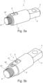
- Fig. 5a-b disclose a second embodiment that differs from the preferred embodiment above mainly in the fastening device 4' being configured in such a way that the transversal element 41' is arranged on the housing 2' and the slot 42' is arranged on the insert 3'.
- This embodiment has the advantage that the cavity inside the housing 2' can be protected from dirt and dust without requiring an external sealing, since there is no opening in the housing 2' that provides access to the cavity inside.
- the second embodiment is similar to the preferred embodiment and the operation of the piston rod end 1' is also similar in both embodiments.
- Reference numerals denoting parts of the second embodiment include an apostrophe but are otherwise identical to the reference numerals of the preferred embodiment. It is advantageous that the transversal element 41' is arranged to extend into the slot 42' at one end and not to extend beyond the surface of the housing 2' at its other end, or to extend only slightly.
- All embodiments of the present invention may comprise at least one bearing element 71, 141 that may be arranged on either or both of the second connector 7 of the piston rod end 1 and the first linear actuator connector 120 of the linear actuator 100 (see Fig. 2b and Fig. 4a-4b ).
- the bearing element 71, 141 is preferably a spherical bearing element such as ball bearings. This has the benefit of absorbing bending forces to which the piston assembly 10 is subjected and preventing damage or breakage along the piston assembly 10.
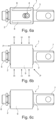
- Fig. 6a-c disclose an external sealing 9 that is mounted on the housing 2 to protect the piston rod end 1 from dust and dirt that might otherwise reach the cavity 23 through the slot 42 in the housing 2.
- adhesive devices 8 in the form of adhesive strips 8 are disclosed.
- the adhesive strips 8 are preferably placed on the housing 2 before insertion of the housing 2 into the sealing tube 9, so that the sealing tube 9 when shrunk onto the housing 2 firmly adheres to the adhesive strips 8 to prevent movement of the sealing tube 9 in relation to the housing 2.
- the adhesive strips are placed longitudinally on the housing 2 but they could alternatively be placed around a circumference of the housing 2 or in other ways. A combination of longitudinal and circumferential placements could also be used, or any other combination of orientations.
- the housing 2 may be made from 1.4301 Stainless Steel and the insert 3 is preferably made from CuSn12 (Material Standard EN 1982). This allows free smooth movement between the insert 3 and the housing 2 which will act as a plain bearing. In addition, both these materials have good corrosion resistance properties. Similar materials may of course also be used within the scope of the present invention, as long as they are suitable for use with a linear actuator in a train coupler.
- the fastening element or elements 41, 41' are preferably secured to the housing 2 or insert 3' by a fixating substance such as Locktite 243 or similar. This ensures that undesired loosening of the transversal element 41, 41' is prevented.
Landscapes
- Engineering & Computer Science (AREA)
- Mechanical Engineering (AREA)
- General Engineering & Computer Science (AREA)
- Physics & Mathematics (AREA)
- Acoustics & Sound (AREA)
- Aviation & Aerospace Engineering (AREA)
- Actuator (AREA)
Claims (15)
- Kolbenstangenende zum Absorbieren von Kräften an einem Linearantrieb und zur Aufnahme eines Zusatzhubs in einer Zugkupplung, wobei das Kolbenstangenende (1) Folgendes umfasst:- ein Gehäuse (2), das einen Hohlraum (23) mit einer Bodenfläche (24) umschließt, wobei sich der Hohlraum (23) in einer Längsrichtung im Gehäuse (2) erstreckt,- einen länglichen Einsatz (3), der zumindest teilweise im Inneren des Hohlraums (23) angeordnet ist,- eine im Inneren des Hohlraums (23) angeordnete Feder (5), wobei die Feder (5) zwischen der Bodenfläche (24) und dem Einsatz (3) angeordnet ist, und- eine Befestigungsvorrichtung (4), die ein Querelement (41) und einen ein Spiel bildenden Längsschlitz (42) umfasst, von denen das oder der eine in dem Gehäuse (2) und das oder der andere in dem Einsatz (3) angeordnet ist und die dafür eingerichtet sind, derart zusammenzuwirken, dass sich das Querelement (41) in einer Querrichtung in Bezug auf das Gehäuse (2) in den Schlitz (42) hinein erstreckt und in dem Spiel beweglich ist, sodass der Einsatz (3) in Bezug auf das Gehäuse (2) beweglich ist, aber nicht aus dem Gehäuse (2) entfernt werden kann,wobei das Kolbenstangenende (1) ferner ein erstes Verbindungsstück (6) zum Verbinden des Kolbenstangenendes (1) mit einem Linearantrieb (100) und ein zweites Verbindungsstück (7) zum Verbinden des Kolbenstangenendes (1) mit einer Zugkupplung umfasst, wobei eines von dem ersten und dem zweiten Verbindungsstück (7) am Gehäuse (2) angeordnet ist und das andere am Einsatz (3) angeordnet ist,dadurch gekennzeichnet, dassder Hohlraum (23) im Wesentlichen zylindrisch ist und wobei vorzugsweise der Einsatz (3) ebenfalls im Wesentlichen zylindrisch ist und einen Durchmesser aufweist, der kleiner oder gleich dem Durchmesser des Hohlraums (23) ist.
- Kolbenstangenende (1) nach Anspruch 1, wobei das Querelement (41) mindestens eine Schraube, einen Bolzen oder einen Stift, vorzugsweise eine Innensechskantschraube, umfasst.
- Kolbenstangenende (1) nach einem der Ansprüche 1 bis 2, wobei das erste Verbindungsstück (6) einen Drehanschlag (21) umfasst, um eine Drehung des Kolbenstangenendes (1) in Bezug auf das erste Verbindungsstück (6) zu verhindern, wobei der Drehanschlag (21) vorzugsweise eine Kontermutter ist, die mit dem ersten Verbindungsstück (6) durch ein Außengewinde an dem ersten Verbindungsstück (6) verbunden ist.
- Kolbenstangenende (1) nach einem der vorhergehenden Ansprüche, wobei der Einsatz (3) einen Dichtungsring (32) umfasst, der an einem Umfang des Einsatzes (3) oder an einer Innenwand des Hohlraums (23) angeordnet ist, um das Eindringen von Schmutz oder Staub in den Hohlraum (23) zu verhindern.
- Kolbenstangenende (1) nach einem der vorhergehenden Ansprüche, wobei das Gehäuse (2) eine äußere Dichtung (9) umfasst, die an einem Außenumfang angeordnet ist, um das Eindringen von Schmutz oder Staub in den Hohlraum (23) zu verhindern.
- Kolbenstangenende (1) nach einem der vorhergehenden Ansprüche, ferner umfassend eine zusätzliche Befestigungsvorrichtung (4), die diametral gegenüber der Befestigungsvorrichtung (4) am Gehäuse (2) und am Einsatz (3) angeordnet ist.
- Kolbenstangenende (1) nach einem der vorhergehenden Ansprüche, wobei der Einsatz (3) das Querelement (41) umfasst und das Gehäuse (2) den Schlitz (42) umfasst, und wobei das Querelement (41) so angeordnet ist, dass es in den Schlitz (42) hineinragt, sich aber nicht über eine Außenfläche des Gehäuses (2) hinaus erstreckt.
- Kolbenstangenende (1) nach einem der vorhergehenden Ansprüche, ferner umfassend ein Lagerelement (71), das auf dem zweiten Verbindungsstück (7) angeordnet ist.
- Kolbenbaugruppe für eine Zugkupplung, umfassend einen Linearantrieb (100) und ein Kolbenstangenende (1) nach einem der Ansprüche 1 bis 8, wobei das Kolbenstangenende (1) an dem Linearantrieb (100) montiert ist, indem das erste Verbindungsstück (6) an dem Kolbenstangenende (1) mit einem Antriebs-Verbindungsstück (150) an einem ersten Ende des Linearantriebs (100) verbunden ist, vorzugsweise durch Verschrauben eines Außengewindes an einem von dem ersten Verbindungsstück (6) und dem Antriebs-Verbindungsstück (150) mit einem Innengewinde des anderen.
- Kolbenbaugruppe nach Anspruch 9, wobei der Linearantrieb (100) einen Elektromotor umfasst, der so angeordnet ist, dass er eine Länge des Antriebs vergrößert oder verkleinert, wobei der Motor so angeordnet ist, dass er mit einer maximalen Motorkraft arbeitet und die Feder (5) des Kolbenstangenendes (1) ferner eine Kraft der Feder (5) aufweist, wobei die Kraft der Feder (5) kleiner oder gleich der maximalen Motorkraft ist.
- Kolbenbaugruppe nach Anspruch 9 oder 10, ferner umfassend ein zweites Kolbenstangenende (1) nach einem der Ansprüche 1 bis 8, wobei das zweite Kolbenstangenende (1) an einem zweiten Ende des Linearantriebs (100) montiert ist.
- Kolbenbaugruppe nach einem der Ansprüche 9 bis 11, ferner umfassend ein Lagerelement (141), das am ersten Verbindungsstück (120) des Linearantriebs (100) angeordnet ist, und vorzugsweise umfassend auch ein Lagerelement (71) am zweiten Verbindungsstück (7) des Kolbenstangenendes (1).
- Abdichtungsverfahren zum Abdichten eines Kolbenstangenendes (1) nach einem der Ansprüche 1 bis 9, wobei das Abdichtungsverfahren Folgendes umfasst:- Bereitstellen eines Kolbenstangenendes (1) nach einem der Ansprüche 1 bis 8,- Einsetzen des Gehäuses (2) des Kolbenstangenendes (1) in ein Dichtungsrohr (9),- Erwärmen mindestens eines Abschnitts (P) des Dichtungsrohrs (9), um das Dichtungsrohr (9) zu schrumpfen, damit es an das Gehäuse (2) passt, wobei der mindestens eine Abschnitt (P) ein Abschnitt ist, der nicht in Kontakt mit der Befestigungsvorrichtung (4) des Gehäuses (2) steht.
- Dichtungsverfahren nach Anspruch 13, wobei mindestens eine Klebevorrichtung (8) vor dem Erhitzen zwischen dem Gehäuse (2) und dem Dichtungsrohr angeordnet wird.
- Dichtungsverfahren nach Anspruch 13 oder 14, wobei mindestens zwei Abschnitte (P) des Dichtungsrohrs (9) erwärmt werden, wobei die mindestens zwei Abschnitte (P) über einen Umfang des Dichtungsrohrs (9) verteilt sind.
Applications Claiming Priority (2)
| Application Number | Priority Date | Filing Date | Title |
|---|---|---|---|
| SE1851586A SE542832C2 (en) | 2018-12-14 | 2018-12-14 | Piston rod end for a linear actuator, piston assembly and sealing method for a piston rod end |
| PCT/SE2019/051183 WO2020122787A1 (en) | 2018-12-14 | 2019-11-22 | Piston rod end for a linear actuator, piston assembly and sealing method for a piston rod end |
Publications (3)
| Publication Number | Publication Date |
|---|---|
| EP3894718A1 EP3894718A1 (de) | 2021-10-20 |
| EP3894718C0 EP3894718C0 (de) | 2025-04-30 |
| EP3894718B1 true EP3894718B1 (de) | 2025-04-30 |
Family
ID=69024576
Family Applications (1)
| Application Number | Title | Priority Date | Filing Date |
|---|---|---|---|
| EP19828349.1A Active EP3894718B1 (de) | 2018-12-14 | 2019-11-22 | Kolbenstangenende für einen linearantrieb, kolbenanordnung und dichtungsverfahren für ein kolbenstangenende |
Country Status (4)
| Country | Link |
|---|---|
| US (1) | US12269517B2 (de) |
| EP (1) | EP3894718B1 (de) |
| SE (1) | SE542832C2 (de) |
| WO (1) | WO2020122787A1 (de) |
Families Citing this family (1)
| Publication number | Priority date | Publication date | Assignee | Title |
|---|---|---|---|---|
| SE545564C2 (en) * | 2022-03-03 | 2023-10-24 | Dellner Couplers Ab | Coupler for a railway vehicle with a biasing device, and method for overhauling a coupler |
Family Cites Families (18)
| Publication number | Priority date | Publication date | Assignee | Title |
|---|---|---|---|---|
| US1074243A (en) | 1912-02-19 | 1913-09-30 | Entpr Equipment Company | Railway draft-rigging. |
| US1293131A (en) | 1916-07-13 | 1919-02-04 | William H Miner | Railway-car draft-rigging. |
| US1447146A (en) | 1921-02-23 | 1923-02-27 | Novak William | Coupling |
| US1674639A (en) | 1925-03-23 | 1928-06-26 | Union Draft Gear Company | Draft gear |
| US1636435A (en) | 1926-03-09 | 1927-07-19 | Herman C Priebe | Friction draft gear |
| USRE25110E (en) * | 1951-09-07 | 1962-01-09 | tucker | |
| US2970703A (en) | 1959-03-04 | 1961-02-07 | Symington Wayne Corp | Rubber draft gear |
| DE2427714A1 (de) | 1973-06-21 | 1975-01-23 | Erik Steen Joergensen | Gleitendes und nachgiebiges tragelement |
| DE2332791C3 (de) * | 1973-06-28 | 1984-09-13 | Stabilus Gmbh, 5400 Koblenz | Gasfeder |
| DE3836897A1 (de) * | 1988-10-29 | 1990-05-03 | Stabilus Gmbh | Ventilierbare schutzhuelle fuer die kolbenstange eines hydropneumatischen verstellelements |
| US5791445A (en) * | 1997-05-26 | 1998-08-11 | Fichtel & Sachs Industries, Inc. | Piston rod-cylinder assembly with shrink-wrap corrosion protective sleeve |
| US6199708B1 (en) * | 1999-03-05 | 2001-03-13 | Asf-Keystone, Inc. | Railcar cushioning device with internal elastomeric spring |
| KR100519624B1 (ko) | 2003-03-03 | 2005-10-11 | (주)삼협 | 길이조절 가스스프링 |
| SE526663C2 (sv) * | 2004-02-04 | 2005-10-18 | Dellner Couplers Ab | Draginrättning för tågkoppel samt deformationsrör härför |
| US7600617B1 (en) * | 2005-03-28 | 2009-10-13 | General Manufacturing Systems, Inc. | Industrial shock absorber for use in a conveyor system |
| US9868453B2 (en) | 2016-05-20 | 2018-01-16 | O-Ring Sales & Service, Inc. | Railcar end unit |
| CN107299950A (zh) | 2017-08-10 | 2017-10-27 | 中国扬子集团滁州扬子空调器有限公司 | 抗剪切型自锁弹簧减震器 |
| US11090559B2 (en) * | 2019-12-31 | 2021-08-17 | Logitech Europe S.A. | Gaming pedal assembly |
-
2018
- 2018-12-14 SE SE1851586A patent/SE542832C2/en unknown
-
2019
- 2019-11-22 US US17/312,682 patent/US12269517B2/en active Active
- 2019-11-22 EP EP19828349.1A patent/EP3894718B1/de active Active
- 2019-11-22 WO PCT/SE2019/051183 patent/WO2020122787A1/en not_active Ceased
Also Published As
| Publication number | Publication date |
|---|---|
| EP3894718A1 (de) | 2021-10-20 |
| CA3122927A1 (en) | 2020-06-18 |
| SE1851586A1 (en) | 2020-06-15 |
| WO2020122787A1 (en) | 2020-06-18 |
| US12269517B2 (en) | 2025-04-08 |
| EP3894718C0 (de) | 2025-04-30 |
| US20220063684A1 (en) | 2022-03-03 |
| SE542832C2 (en) | 2020-07-14 |
Similar Documents
| Publication | Publication Date | Title |
|---|---|---|
| CA2749493C (en) | Slotted spring vibration isolator | |
| MXPA01012576A (es) | Miembro elastico con elemento deformado y metodo para su formacion. | |
| JP6126553B2 (ja) | ハウジングカバー、特にプラスチック製オイルサンプ | |
| CA2839947A1 (en) | Connecting rod/piston arrangement for alternative compressor and process for assembling connecting rod/piston arrangement for alternative compressor | |
| EP3894718B1 (de) | Kolbenstangenende für einen linearantrieb, kolbenanordnung und dichtungsverfahren für ein kolbenstangenende | |
| CN101484722B (zh) | 摩擦阻尼器 | |
| US20120219353A1 (en) | Joint having a ball head fastened to a pin and plain-bearing film for such a joint | |
| CA3122927C (en) | Piston rod end for a linear actuator, piston assembly and sealing method for a piston rod end | |
| CN105422706B (zh) | 轴承衬套和振荡阻尼连接结构 | |
| US20150037086A1 (en) | Thread-reinforced axial coupling | |
| JP5444426B2 (ja) | 自動車で使用される継手装置 | |
| US6871631B2 (en) | Throttle valve body | |
| US20080230319A1 (en) | Device for Securing and Lubricating Bushings | |
| US20080145141A1 (en) | Joint and/or Bearing Arrangement | |
| US6779940B2 (en) | Fastening device for a linear drive | |
| US20050005469A1 (en) | Measuring point bolt and method of making the bolt | |
| US11525483B2 (en) | Self-centering flexible coupling | |
| US10647156B2 (en) | Axle shock-load absorber and guard | |
| US10766328B2 (en) | Spring strut support mount | |
| US20050262963A1 (en) | Divided connecting rod having a screwed connecting rod cover | |
| US20090149264A1 (en) | Accommodation housing for homokinetic joints | |
| RU172956U1 (ru) | Разъёмный защитный гофрированный чехол | |
| RU169402U1 (ru) | Разъёмный защитный гофрированный чехол | |
| KR101761365B1 (ko) | 제어밸브의 축 이음 장치 | |
| JP2016023770A (ja) | 補機駆動ベルト用のテンショナユニット |
Legal Events
| Date | Code | Title | Description |
|---|---|---|---|
| STAA | Information on the status of an ep patent application or granted ep patent |
Free format text: STATUS: UNKNOWN |
|
| STAA | Information on the status of an ep patent application or granted ep patent |
Free format text: STATUS: THE INTERNATIONAL PUBLICATION HAS BEEN MADE |
|
| PUAI | Public reference made under article 153(3) epc to a published international application that has entered the european phase |
Free format text: ORIGINAL CODE: 0009012 |
|
| STAA | Information on the status of an ep patent application or granted ep patent |
Free format text: STATUS: REQUEST FOR EXAMINATION WAS MADE |
|
| 17P | Request for examination filed |
Effective date: 20210617 |
|
| AK | Designated contracting states |
Kind code of ref document: A1 Designated state(s): AL AT BE BG CH CY CZ DE DK EE ES FI FR GB GR HR HU IE IS IT LI LT LU LV MC MK MT NL NO PL PT RO RS SE SI SK SM TR |
|
| DAV | Request for validation of the european patent (deleted) | ||
| DAX | Request for extension of the european patent (deleted) | ||
| STAA | Information on the status of an ep patent application or granted ep patent |
Free format text: STATUS: EXAMINATION IS IN PROGRESS |
|
| 17Q | First examination report despatched |
Effective date: 20230615 |
|
| GRAP | Despatch of communication of intention to grant a patent |
Free format text: ORIGINAL CODE: EPIDOSNIGR1 |
|
| STAA | Information on the status of an ep patent application or granted ep patent |
Free format text: STATUS: GRANT OF PATENT IS INTENDED |
|
| INTG | Intention to grant announced |
Effective date: 20250102 |
|
| GRAS | Grant fee paid |
Free format text: ORIGINAL CODE: EPIDOSNIGR3 |
|
| GRAA | (expected) grant |
Free format text: ORIGINAL CODE: 0009210 |
|
| STAA | Information on the status of an ep patent application or granted ep patent |
Free format text: STATUS: THE PATENT HAS BEEN GRANTED |
|
| AK | Designated contracting states |
Kind code of ref document: B1 Designated state(s): AL AT BE BG CH CY CZ DE DK EE ES FI FR GB GR HR HU IE IS IT LI LT LU LV MC MK MT NL NO PL PT RO RS SE SI SK SM TR |
|
| REG | Reference to a national code |
Ref country code: CH Ref legal event code: EP Ref country code: GB Ref legal event code: FG4D |
|
| REG | Reference to a national code |
Ref country code: DE Ref legal event code: R096 Ref document number: 602019069414 Country of ref document: DE |
|
| REG | Reference to a national code |
Ref country code: IE Ref legal event code: FG4D |
|
| U01 | Request for unitary effect filed |
Effective date: 20250512 |
|
| U07 | Unitary effect registered |
Designated state(s): AT BE BG DE DK EE FI FR IT LT LU LV MT NL PT RO SE SI Effective date: 20250516 |
|
| PG25 | Lapsed in a contracting state [announced via postgrant information from national office to epo] |
Ref country code: ES Free format text: LAPSE BECAUSE OF FAILURE TO SUBMIT A TRANSLATION OF THE DESCRIPTION OR TO PAY THE FEE WITHIN THE PRESCRIBED TIME-LIMIT Effective date: 20250430 |
|
| PG25 | Lapsed in a contracting state [announced via postgrant information from national office to epo] |
Ref country code: NO Free format text: LAPSE BECAUSE OF FAILURE TO SUBMIT A TRANSLATION OF THE DESCRIPTION OR TO PAY THE FEE WITHIN THE PRESCRIBED TIME-LIMIT Effective date: 20250730 Ref country code: GR Free format text: LAPSE BECAUSE OF FAILURE TO SUBMIT A TRANSLATION OF THE DESCRIPTION OR TO PAY THE FEE WITHIN THE PRESCRIBED TIME-LIMIT Effective date: 20250731 |
|
| PG25 | Lapsed in a contracting state [announced via postgrant information from national office to epo] |
Ref country code: PL Free format text: LAPSE BECAUSE OF FAILURE TO SUBMIT A TRANSLATION OF THE DESCRIPTION OR TO PAY THE FEE WITHIN THE PRESCRIBED TIME-LIMIT Effective date: 20250430 |
|
| PG25 | Lapsed in a contracting state [announced via postgrant information from national office to epo] |
Ref country code: HR Free format text: LAPSE BECAUSE OF FAILURE TO SUBMIT A TRANSLATION OF THE DESCRIPTION OR TO PAY THE FEE WITHIN THE PRESCRIBED TIME-LIMIT Effective date: 20250430 |
|
| PG25 | Lapsed in a contracting state [announced via postgrant information from national office to epo] |
Ref country code: RS Free format text: LAPSE BECAUSE OF FAILURE TO SUBMIT A TRANSLATION OF THE DESCRIPTION OR TO PAY THE FEE WITHIN THE PRESCRIBED TIME-LIMIT Effective date: 20250731 |
|
| PG25 | Lapsed in a contracting state [announced via postgrant information from national office to epo] |
Ref country code: IS Free format text: LAPSE BECAUSE OF FAILURE TO SUBMIT A TRANSLATION OF THE DESCRIPTION OR TO PAY THE FEE WITHIN THE PRESCRIBED TIME-LIMIT Effective date: 20250830 |
|
| U20 | Renewal fee for the european patent with unitary effect paid |
Year of fee payment: 7 Effective date: 20251117 |
|
| PG25 | Lapsed in a contracting state [announced via postgrant information from national office to epo] |
Ref country code: SM Free format text: LAPSE BECAUSE OF FAILURE TO SUBMIT A TRANSLATION OF THE DESCRIPTION OR TO PAY THE FEE WITHIN THE PRESCRIBED TIME-LIMIT Effective date: 20250430 |
|
| PG25 | Lapsed in a contracting state [announced via postgrant information from national office to epo] |
Ref country code: CZ Free format text: LAPSE BECAUSE OF FAILURE TO SUBMIT A TRANSLATION OF THE DESCRIPTION OR TO PAY THE FEE WITHIN THE PRESCRIBED TIME-LIMIT Effective date: 20250430 |
|
| PG25 | Lapsed in a contracting state [announced via postgrant information from national office to epo] |
Ref country code: SK Free format text: LAPSE BECAUSE OF FAILURE TO SUBMIT A TRANSLATION OF THE DESCRIPTION OR TO PAY THE FEE WITHIN THE PRESCRIBED TIME-LIMIT Effective date: 20250430 |