EP3894150B1 - Klingenanordnungbefestigungsmechanismus und modulare rasiereranordnung - Google Patents
Klingenanordnungbefestigungsmechanismus und modulare rasiereranordnung Download PDFInfo
- Publication number
- EP3894150B1 EP3894150B1 EP19817325.4A EP19817325A EP3894150B1 EP 3894150 B1 EP3894150 B1 EP 3894150B1 EP 19817325 A EP19817325 A EP 19817325A EP 3894150 B1 EP3894150 B1 EP 3894150B1
- Authority
- EP
- European Patent Office
- Prior art keywords
- attachment mechanism
- handle
- assembly
- track
- razor
- Prior art date
- Legal status (The legal status is an assumption and is not a legal conclusion. Google has not performed a legal analysis and makes no representation as to the accuracy of the status listed.)
- Active
Links
Images


Classifications
-
- B—PERFORMING OPERATIONS; TRANSPORTING
- B26—HAND CUTTING TOOLS; CUTTING; SEVERING
- B26B—HAND-HELD CUTTING TOOLS NOT OTHERWISE PROVIDED FOR
- B26B21/00—Razors of the open or knife type; Safety razors or other shaving implements of the planing type; Hair-trimming devices involving a razor-blade; Equipment therefor
- B26B21/08—Razors of the open or knife type; Safety razors or other shaving implements of the planing type; Hair-trimming devices involving a razor-blade; Equipment therefor involving changeable blades
- B26B21/14—Safety razors with one or more blades arranged transversely to the handle
- B26B21/22—Safety razors with one or more blades arranged transversely to the handle involving several blades to be used simultaneously
- B26B21/222—Safety razors with one or more blades arranged transversely to the handle involving several blades to be used simultaneously with the blades moulded into, or attached to, a changeable unit
- B26B21/225—Safety razors with one or more blades arranged transversely to the handle involving several blades to be used simultaneously with the blades moulded into, or attached to, a changeable unit the changeable unit being resiliently mounted on the handle
-
- B—PERFORMING OPERATIONS; TRANSPORTING
- B26—HAND CUTTING TOOLS; CUTTING; SEVERING
- B26B—HAND-HELD CUTTING TOOLS NOT OTHERWISE PROVIDED FOR
- B26B21/00—Razors of the open or knife type; Safety razors or other shaving implements of the planing type; Hair-trimming devices involving a razor-blade; Equipment therefor
- B26B21/40—Details or accessories
- B26B21/52—Handles, e.g. tiltable, flexible
- B26B21/521—Connection details, e.g. connection to razor heads
-
- B—PERFORMING OPERATIONS; TRANSPORTING
- B26—HAND CUTTING TOOLS; CUTTING; SEVERING
- B26B—HAND-HELD CUTTING TOOLS NOT OTHERWISE PROVIDED FOR
- B26B21/00—Razors of the open or knife type; Safety razors or other shaving implements of the planing type; Hair-trimming devices involving a razor-blade; Equipment therefor
- B26B21/40—Details or accessories
- B26B21/52—Handles, e.g. tiltable, flexible
- B26B21/523—Extendible or foldable handles; Extensions
Definitions
- the present description relates to a modular razor that has an interchangeable handle. More specifically, the description relates to a pivotable attachment device that may be selectively attachable to a blade assembly and to a razor handle, as well as a razor assembly comprising a handle, blade assembly, and the pivotable attachment device.
- a common problem with razor assemblies having a single type of razor handle available is that the razor assembly is a "one size fits all" for potential customers or razor users. This may be frustrating to a customer who may desire a handle that is shaped differently to improve their ability to adequately manipulate the razor, for example, a smaller handle. The market has responded to this customer demand.
- US 2013/061481 relates to safety razor with a disc-like form handle to enhance a user's manipulation of the razor assembly.
- US 2014/230256 which also relates to a safety razor having a substrate retaining member forming at least a partial ring, which further comprises elastomeric material to provide a softer feel to the user.
- US 1 059 487 relates to a safety razor that can be adjusted to different angles, to secure a desirable cutting angle.
- WO 2018/007845 A1 relates to a reconfigurable shaving razor.
- the razor assembly may be specifically adapted for shaving facial, head, and/or body hair.
- a removable and pivotable attachment mechanism is provided as well as a razor assembly including a removable and pivotable attachment mechanism.
- a razor assembly is provided.
- the razor assembly according to the invention is defined in claim 1.
- the handle distal end and the attachment mechanism may comprise a track including a guide rail and the other of the distal end and the attachment mechanism may comprise a channel configured to releasably connect with the track and guide rail so as to provide the first pivotal movement between the handle and the attachment mechanism.
- the attachment mechanism may comprise a top portion and bottom portion which form the channel and the distal end of the handle may comprise the track and guide rail.
- One or more of the top and bottom portions of the attachment mechanism may further include outer portions, wherein the outer portions are adapted to secure the attachment mechanism to the track of the handle.
- the guide rail has a smaller width than the track.
- One or more of the top and bottom portions of the attachment mechanism may further include a gripping feature.
- One or more of the top and bottom portions of the attachment mechanism may further include a button for releasing the blade assembly.
- the first pivotal movement may be configured to rotate within a range of 45 degrees to each side of the first axis A-A.
- one of the handle distal end and the attachment mechanism may include a recess, and the other of the handle distal end and the attachment mechanism may comprise a return mechanism configured to connect to the recess so as to provide a return force against the first pivotal movement.
- the return mechanism is elastically deformable such that when the attachment mechanism is in a rotated position, the return mechanism may be in a deformed state.
- the attachment mechanism may be entirely or substantially circular.
- the track of the handle may have an arcuate shape.
- the attachment mechanism and blade assembly may rotate in concert relative to the handle.
- the attachment mechanism is oval shaped and the distal end of the handle comprises an elastically deformable material such that when the attachment mechanism is in a rotated position, the handle distal end is in a deformed state.
- an interchangeable handle can provide greater comfort and manipulability to the user. Further, the pivotable aspect of the attachment mechanism facilitates freedom of movement of the razor head, thus reducing the risk of nicks and cuts to a user during a shaving operation.
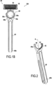
- FIGS. 1A and 1B show a razor assembly 100 having a blade assembly 20, handle 40, and attachment mechanism 50.
- the blade assembly 20 may have a housing 22 that may be hollow and generally form a rectangular parallelepiped; however, the housing 22 may be any other suitable shape.
- the blade assembly 20 may further include a blade assembly attachment portion 24 configured to attach the blade assembly 20 to the attachment mechanism 50.
- the housing 22 Secured within the housing 22 is at least one blade 30.
- a plurality of blades 30 are shown; however, it is contemplated that the blade assembly 20 may have any number of blades 30.
- the blades 30 that are shown are elongate in shape; however, it is contemplated that the blades 30 may be formed into any other suitable shape. It is also envisioned that the housing 22 may secure an exfoliating element rather than blades 30.
- the handle 40 may be elongated extending along a vertical central axis A-A.
- the handle 40 may be shaped to adapt to the natural contours of a hand.
- the handle 40 has a distal end 40a and a proximal end 40b.
- the distal end 40a of the handle 40 may have an arcuate shape and may form a track 42 that is adapted to connect to the attachment mechanism 50.
- the track 42 may include at least one guide rail 44.
- the guide rail 44 may be formed as a step having a width "Wg" in a range of 1mm to 8mm, more specifically 2.5mm.
- the width "Wt” of the track 42 may be in a range of 3mm to 12mm, more specifically 5mm.
- the width of the guide rail 44 may be smaller than the width of the track 42.
- the thickness "Wa" of the track 42 may be in a range of 0.5 to 4mm, more specifically 1.5mm.
- the track 42 and guide rail 44 may be integrally formed.
- the handle 40 may further include a recess 46 that is configured to receive a return mechanism 59 of the attachment mechanism 50.
- the recess 46 may be positioned along the vertical central axis A-A. However, the recess 46 may be positioned in any other suitable location. For example, the recess 46 may be positioned in the attachment mechanism 50 and the return mechanism 59 on the handle.
- the attachment mechanism 50 may be attached to the distal end 40a of the handle 40.
- the attachment mechanism 50 may include a button 52 for the selective attachment or release of the blade assembly 20.
- the blade assembly may be interchangeable, in particular, when a blade or blades of the blade assembly have been blunted. However, it is also envisioned that the blade assembly 20 and attachment mechanism may be integrated or may be fixedly attached.
- the attachment mechanism 50 may have a circular or substantially circular shape.
- the diameter of the attachment mechanism may be within a range of 5mm to 40mm, more specifically from 10mm to 30mm, more specifically about 20mm.
- the attachment mechanism according to the claimed invention has an oval shape, which will be discussed in detail with reference to FIGS. 6 and 7 .
- the attachment mechanism 50 may be removable from the handle 40.
- the attachment mechanism 50 may be configured to be used as a handle.
- the attachment mechanism 50 may have a top portion 55a ( Fig. 1A ) and a bottom portion 55b ( Fig. 1B ).
- the top and bottom portions 55a, 55b may include respective outer portions 56a, 56b.
- the outer portions 56a, 56b may be adapted to secure the attachment mechanism 50 to the track 42 of the handle 40.
- the top portion 55a and bottom portion 55b of the attachment mechanism 50 may be connected to each other forming a channel 57.
- the channel 57 may be located between the respective outer portions 56a, 56b of the top and bottom portions 55a, 55b.
- the channel 57 may be adapted to interlock with the rail 42 of the handle 40.
- the attachment mechanism 50 may be configured to provide a return force to the first pivotal movement.
- the attachment mechanism 50 may include a return mechanism 58.
- the return mechanism 58 may be flexible.
- the return mechanism 58 may comprise at least one flexible pin or finger or tongue.
- the return mechanism 58 may be adapted to exert a return torque on the recess 46.
- the return torque may be exerted on the recess 46 when the attachment mechanism 50 is rotated.
- the return torque generated by the return mechanism 58 may be in a range of 0 to 30 Nmm, more specifically between 10 and 30 Nmm, and even more specifically between 15 and 25 Nmm.
- An increase of the return toque may depend on the amount that the attachment mechanism 50 is rotated or the angle.
- the increase of the return toque per degree may lie between 0.5 Nmm and 2 Nmm, specifically between 0.67 Nmm and 2 Nmm, and even more specifically between 1 and 1.67 Nmm.
- the return mechanism 58 may comprise any material having a high elasticity, for example, an elastomer.
- the return mechanism 58 may be configured to connect with the recess 46 in the handle 40.
- the return mechanism 58 is depicted on the attachment mechanism 50, it is also envisioned that the return mechanism 58 may be formed on the handle 40 while the attachment mechanism 50 may have a corresponding recess.
- the return mechanism 58 may be disposed at least partially inside of the attachment mechanism 50.
- the return mechanism 58 may have a substantially arcuate shape that is configured to interlock with the distal end 40a of the handle 40.
- the return mechanism 58 may include a projection that is configured to removably connect with the recess 46 in the handle 40.
- the return mechanism 58 may comprise at least one flexible tongue that is configured to control the movement of the attachment mechanism 50.
- the at least one tongue may extend from an inner surface of the arc toward a centroid of the arc.
- the return mechanism 58 may include a pair of flexible tongues that are configured to control the movement of the attachment mechanism 50.
- the each of the pair of tongues may extend from an inner surface of the arc toward the centroid of the arc.
- the pair of tongues may be diametrically disposed.
- the attachment mechanism 50 may include inner channels are that configured to engage at least one tongue. At least one tongue may be configured to exert a return torque on the inner channel.
- the top and bottom portions 55a, 55b of the attachment mechanism 50 may have corresponding pins 59a and holes 59b so that they may be attached to each other.
- the attachment may be any suitable means, for example a snap fit.
- the guide rail 44 of the handle 40 may be configured to fit within channel 57 of the attachment mechanism 50.
- the track 42 of the handle 40 may be configured to slidably engage the respective outer portions 56a, 56b of the top and bottom portions 55a, 55b of the attachment mechanism 50.
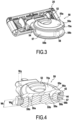
- the top and bottom portions 55a, 55b of the attachment mechanism 50 may include corresponding top and bottom gripping features 70a, 70b (shown on FIGS. 1A , 1B , 3, and 4 ).
- the gripping features 70a, 70b may be selected from, but not limited to, projections, rubber portions/layers, or surface texture. It is also envisioned that only one of the top or bottom portions 55a, 55b includes gripping features 70a, 70b.
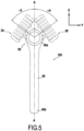
- the blade assembly 20 is configured to pivot relative to the handle 40.
- the blade assembly 20 may be configured to pivot within a range of - ⁇ ⁇ x ⁇ + ⁇ relative to a central axis A-A of the handle 40.
- a razor assembly 100 may have a blade assembly 20 in a rest position where the center of the blade assembly 20 is aligned or substantially aligned with the central axis A-A.
- a user may place the blade assembly 20 in a first pivot position at an angle + ⁇ by applying a force on the blade assembly 20 along the y-axis. This force transitions the return mechanism from an equilibrium state to a deformed state. Once the blade assembly 20 is released, or does not have the external force applied thereon, the blade assembly 20 may rotate back to the rest position by operation of the return mechanism 58 moving from the deformed state to the equilibrium state.
- the respective outer portions 56a, 56b, of the attachment mechanism 50 act as guards that secure the attachment mechanism 50 to the track 42 of the handle 40 during rotation of the attachment mechanism 50.
- a user may first obtain the attachment mechanism 50. Thereafter, a user may connect the attachment mechanism connection portion 54 with the blade assembly attachment portion 24. With this configuration, a user may opt to use attachment mechanism 50 as a handle for shaving. This configuration is beneficial in that the economical size of the attachment mechanism 50 connected with the blade assembly 20 facilitates storage and portability.
- a user may desire to use an elongated handle 40.
- the user may take a further step of connecting the attachment mechanism 50 with the handle 40. This may be achieved by connecting the return mechanism 58 to the corresponding recess 46 in the handle 40, and then positioning the track 44 within the corresponding channel 57.
- the blade assembly 20 is pivotable relative to the handle 40.
- a pivotable blade assembly 20 reduces the risk of nicks and cuts during a shaving operation because the blade assembly 20 can adapt to the contours in human skin.
- a user is able to customize the handle 40.
- a user may desire the have a larger handle 40 or a smaller handle 40 to enhance their ability to effectively manipulate the razor assembly 100.
- a user may desire to have a particular handle shape, e.g., with a dramatic curve or angle, and is thus able to attach that handle 40 with the attachment mechanism 50 and blade assembly 20 to create a customized razor assembly 100. This is beneficial because a user feels more comfortable during a shaving operation. Also, by enhancing the level of comfort, the risk of nicks and cuts can be reduced.
- attachment mechanism 60 is substantially the same as attachment mechanism 50, thus the differences will be discussed and like references will be used instead of repeating excerpts of the description.
- the attachment mechanism 60 may be entirely or substantially oval shaped having a minor axis with a range of 5-40mm, more specifically 10-30mm, more specifically about 20mm and a major axis with a range of 15-50mm, more specifically 20-40mm, more specifically about 30mm.
- the intersection of the major and minor axes may or may not be coincident with the center of the attachment mechanism 60, thus, the attachment mechanism 60 may have an elliptical or egg shape.
- the attachment mechanism may not include a return mechanism.
- the track 42 of the handle 40 may be configured to control the return of the attachment mechanism 60 into the rest position. This may be achieved, for example, by the track 42 being comprised of an elastic material.
- the track 42 in operation, for example, if a force is applied to the attachment mechanism 60 which orients it into a rotated position, the track 42 is in a deformed state as a result. Once the attachment mechanism 60 is released, the track 42 may return to its equilibrium position, thus urging the attachment mechanism 60 back into the rest position.
Landscapes
- Life Sciences & Earth Sciences (AREA)
- Forests & Forestry (AREA)
- Engineering & Computer Science (AREA)
- Mechanical Engineering (AREA)
- Dry Shavers And Clippers (AREA)
- Scissors And Nippers (AREA)
Claims (10)
- Rasiereranordnung (100), umfassend:eine Klingenanordnung (20), die konfiguriert ist, um sich mit einem Befestigungsmechanismus (50) lösbar zu verbinden;einen Griff (40), der ein distales Ende (40a) aufweist, das konfiguriert ist, um sich mit dem Befestigungsmechanismus (50) lösbar zu verbinden, das eine erste Schwenkbewegung um eine erste Achse (A-A) zwischen dem Griff (40) und dem Befestigungsmechanismus (50) ermöglicht;wobei der Befestigungsmechanismus (50) einen Verbindungsabschnitt (54) umfasst, der konfiguriert ist, um eine zweite Schwenkbewegung zwischen der Klingenanordnung (20) und dem Befestigungsmechanismus (50) bereitzustellen,wobei der Griff (40) und der Befestigungsmechanismus (50) konfiguriert sind, um eine Rückstellkraft gegen die erste Schwenkbewegung bereitzustellen,dadurch gekennzeichnet, dassder Befestigungsmechanismus (50) oval geformt ist und das distale Ende (40a) des Griffs ein elastisch verformbares Material derart umfasst, dass, wenn der Befestigungsmechanismus (50) sich in einer gedrehten Position befindet, das distale Ende (40a) des Griffs (40) sich in einem verformten Zustand befindet.
- Rasiereranordnung (100) nach Anspruch 1, wobei eines von dem distalen Ende (40a) des Griffs (40) und dem Befestigungsmechanismus (50) eine Bahn (42), die eine Führungsschiene (44) einschließt, und das andere von dem distalen Ende (40a) und dem Befestigungsmechanismus (50) einen Kanal (57) umfasst, der konfiguriert ist, um sich mit der Bahn (42) und der Führungsschiene (44) lösbar zu verbinden, um die erste Schwenkbewegung zwischen dem Griff (40) und dem Befestigungsmechanismus (50) bereitzustellen.
- Rasiereranordnung (100) nach Anspruch 2, wobei der Befestigungsmechanismus (50) einen oberen Abschnitt und einen unteren Abschnitt, die den Kanal (57) ausbilden, umfasst und das distale Ende (40a) des Griffs (40) die Bahn (42) und die Führungsschiene (44) umfasst.
- Rasiereranordnung (100) nach Anspruch 3, wobei einer oder mehrere des oberen und des unteren Abschnitts des Befestigungsmechanismus (50) ferner Außenabschnitte (56a, 56b) einschließen, wobei die Außenabschnitte (56a, 56b) angepasst sind, um den Befestigungsmechanismus (50) an der Bahn (42) des Griffs (40) festzumachen.
- Rasiereranordnung (100) nach einem der Ansprüche 3 oder 4, wobei die Führungsschiene (42) eine kleinere Breite als die Bahn (44) aufweist.
- Rasiereranordnung (100) nach einem der Ansprüche 3 bis 5, wobei einer oder mehrere des oberen und des unteren Abschnitts des Befestigungsmechanismus (50) ferner ein Greifmerkmal (70a, 70b) einschließen.
- Rasiereranordnung (100) nach einem der Ansprüche 3 bis 6, wobei einer oder mehrere des oberen und des unteren Abschnitts des Befestigungsmechanismus (50) ferner einen Knopf (52) zum Freigeben der Klingenanordnung (20) einschließen.
- Rasiereranordnung (100) nach einem der Ansprüche 1 bis 7, wobei die erste Schwenkbewegung konfiguriert ist, um sich innerhalb eines Bereichs von 45 Grad zu jeder Seite der ersten Achse A-A zu drehen.
- Rasiereranordnung (100) nach einem der Ansprüche 2 bis 8, wobei die Bahn (42) des Griffs (40) eine bogenförmige Form aufweist.
- Rasiereranordnung (100) nach einem der Ansprüche 1 bis 9, wobei der Befestigungsmechanismus (50) und die Klingenanordnung (20) sich bezüglich des Griffs (40) gemeinsam drehen.
Applications Claiming Priority (2)
| Application Number | Priority Date | Filing Date | Title |
|---|---|---|---|
| EP18212725.8A EP3666479B1 (de) | 2018-12-14 | 2018-12-14 | Klingenanordnungbefestigungsmechanismus und modulare rasieranordnung |
| PCT/EP2019/084960 WO2020120703A1 (en) | 2018-12-14 | 2019-12-12 | Blade assembly attachment mechanism and modular razor assembly |
Publications (2)
| Publication Number | Publication Date |
|---|---|
| EP3894150A1 EP3894150A1 (de) | 2021-10-20 |
| EP3894150B1 true EP3894150B1 (de) | 2024-07-31 |
Family
ID=64665693
Family Applications (2)
| Application Number | Title | Priority Date | Filing Date |
|---|---|---|---|
| EP18212725.8A Active EP3666479B1 (de) | 2018-12-14 | 2018-12-14 | Klingenanordnungbefestigungsmechanismus und modulare rasieranordnung |
| EP19817325.4A Active EP3894150B1 (de) | 2018-12-14 | 2019-12-12 | Klingenanordnungbefestigungsmechanismus und modulare rasiereranordnung |
Family Applications Before (1)
| Application Number | Title | Priority Date | Filing Date |
|---|---|---|---|
| EP18212725.8A Active EP3666479B1 (de) | 2018-12-14 | 2018-12-14 | Klingenanordnungbefestigungsmechanismus und modulare rasieranordnung |
Country Status (5)
| Country | Link |
|---|---|
| US (1) | US12115691B2 (de) |
| EP (2) | EP3666479B1 (de) |
| KR (1) | KR20210102202A (de) |
| CN (1) | CN113015605B (de) |
| WO (1) | WO2020120703A1 (de) |
Families Citing this family (7)
| Publication number | Priority date | Publication date | Assignee | Title |
|---|---|---|---|---|
| EP3666479B1 (de) * | 2018-12-14 | 2024-01-24 | BIC Violex Single Member S.A. | Klingenanordnungbefestigungsmechanismus und modulare rasieranordnung |
| EP4201612A1 (de) * | 2021-12-22 | 2023-06-28 | BIC Violex Single Member S.A. | Kupplungsmechanismus für eine rasiervorrichtung |
| USD1092855S1 (en) * | 2023-05-18 | 2025-09-09 | Dorco Co., Ltd. | Razor handle |
| USD1094884S1 (en) * | 2023-05-18 | 2025-09-23 | Dorco Co., Ltd. | Razor handle |
| USD1092856S1 (en) * | 2023-05-18 | 2025-09-09 | Dorco Co., Ltd. | Razor handle |
| JP1777475S (ja) * | 2023-05-18 | 2024-08-09 | かみそりの柄 | |
| KR20240170414A (ko) * | 2023-05-26 | 2024-12-03 | 주식회사 도루코 | 면도기 카트리지 |
Family Cites Families (25)
| Publication number | Priority date | Publication date | Assignee | Title |
|---|---|---|---|---|
| US1059487A (en) | 1911-12-09 | 1913-04-22 | Walla Leviston | Safety-razor. |
| GB2126470A (en) * | 1982-09-09 | 1984-03-28 | Clive Graham Williams | A fork |
| JPH0422388A (ja) * | 1990-05-18 | 1992-01-27 | Kaijirushi Hamono Kaihatsu Center:Kk | 安全かみそり |
| US6615498B1 (en) * | 2000-03-13 | 2003-09-09 | Warner-Lambert Company | Flexible member for a shaving razor |
| DE60203153T2 (de) * | 2001-10-22 | 2006-01-26 | Eveready Battery Co., Inc. | Rasiergerät |
| AU2009260609A1 (en) * | 2008-06-19 | 2009-12-23 | The Gillette Company | Safety razor having pivotable blade unit |
| US8205344B2 (en) * | 2008-08-20 | 2012-06-26 | The Gillette Company | Safety razor having pivotable blade unit |
| US20100313426A1 (en) * | 2009-06-12 | 2010-12-16 | Terence Gordon Royle | Safety razor with pivot and rotation |
| US8474144B2 (en) * | 2009-08-12 | 2013-07-02 | The Gillette Company | Safety razor with rotational movement and locking button |
| US8720072B2 (en) * | 2010-08-11 | 2014-05-13 | Thomas J. Bucco | Razor with three-axis multi-position capability |
| US8745882B2 (en) | 2010-09-29 | 2014-06-10 | The Gillette Company | Flexible and separable portion of a razor handle |
| US20130061481A1 (en) | 2011-09-08 | 2013-03-14 | Sean Joseph Cooney | Safety razor |
| DE202012002692U1 (de) * | 2012-03-15 | 2013-03-14 | Suat Ellik | Nassrasierstab mit Schwingkopfgelenk für moderne Klingen |
| US8938885B2 (en) * | 2012-05-01 | 2015-01-27 | The Gillette Company | Razor handle with a rotatable portion |
| US20140230256A1 (en) | 2013-02-20 | 2014-08-21 | The Gillette Company | Hand held device |
| EP2902156B1 (de) * | 2014-01-31 | 2017-11-22 | Feintechnik GmbH Eisfeld | Rasierer mit einem Griff und einer drehbaren Schneideinheit |
| JP2017510335A (ja) * | 2014-02-28 | 2017-04-13 | ビック・バイオレクス・エス・エー | 孔部内にインサートを備える剃刀の柄及びそのような剃刀の柄を備える剃刀 |
| US20150266191A1 (en) * | 2014-03-24 | 2015-09-24 | Michael J. MAIMONE | Razor with handle having articulable joint |
| US10131063B2 (en) * | 2015-09-29 | 2018-11-20 | The Gillette Company Llc | Adapter for attaching a razor cartridge to a razor handle |
| WO2018007845A1 (en) * | 2016-07-08 | 2018-01-11 | Bic Violex S.A. | Reconfigurable shaving razors with articulating head |
| US11007661B2 (en) | 2016-07-08 | 2021-05-18 | Bic-Violex Sa | Reconfigurable shaving razors |
| EP3348363B1 (de) * | 2017-01-17 | 2019-07-24 | BIC-Violex S.A. | Rasierhandgriffsystem zum halten einer kartusche schwenkbar um zwei achsen |
| EP3348364B1 (de) * | 2017-01-17 | 2020-04-15 | BIC-Violex S.A. | Griff für einen rasierapparat zur ermöglichung der drehbewegung einer kartusche |
| KR101887119B1 (ko) * | 2017-11-21 | 2018-08-09 | 주식회사 도루코 | 면도기 조립체 |
| EP3666479B1 (de) * | 2018-12-14 | 2024-01-24 | BIC Violex Single Member S.A. | Klingenanordnungbefestigungsmechanismus und modulare rasieranordnung |
-
2018
- 2018-12-14 EP EP18212725.8A patent/EP3666479B1/de active Active
-
2019
- 2019-12-12 EP EP19817325.4A patent/EP3894150B1/de active Active
- 2019-12-12 WO PCT/EP2019/084960 patent/WO2020120703A1/en not_active Ceased
- 2019-12-12 KR KR1020217014234A patent/KR20210102202A/ko not_active Ceased
- 2019-12-12 CN CN201980075049.4A patent/CN113015605B/zh active Active
- 2019-12-12 US US17/295,465 patent/US12115691B2/en active Active
Also Published As
| Publication number | Publication date |
|---|---|
| EP3666479B1 (de) | 2024-01-24 |
| US20210402629A1 (en) | 2021-12-30 |
| EP3894150A1 (de) | 2021-10-20 |
| US12115691B2 (en) | 2024-10-15 |
| EP3666479A1 (de) | 2020-06-17 |
| CN113015605A (zh) | 2021-06-22 |
| CN113015605B (zh) | 2023-09-19 |
| KR20210102202A (ko) | 2021-08-19 |
| WO2020120703A1 (en) | 2020-06-18 |
Similar Documents
| Publication | Publication Date | Title |
|---|---|---|
| US12115691B2 (en) | Blade assembly attachment mechanism and modular razor assembly | |
| US20200171688A1 (en) | Safety razor handle | |
| US8726528B2 (en) | Electric head shaver | |
| US8782911B1 (en) | Versatile shaver | |
| US10252433B2 (en) | Razor with a resilient holder | |
| CN103189170B (zh) | 具有三轴多位置性能的剃刀 | |
| JP2020516416A (ja) | 剃毛かみそりシステム及び製造方法 | |
| CN107810092A (zh) | 剃须刀刀架的保护器、剃须组件、湿式剃须刀、使用这种湿式剃须刀的方法以及制造这种保护器的方法 | |
| US10668637B1 (en) | Cranial shaving device | |
| EP3030386B1 (de) | Elektrische haarschneidemaschine | |
| JP2020516414A (ja) | 剃毛かみそりシステム及び製造方法 | |
| US20010004896A1 (en) | Hair-cutting system including a hair-cutting apparatus and a comb device | |
| WO2019016163A1 (en) | SAFETY RAZOR HANDLE | |
| CN113084878B (zh) | 一种剃刀或剃刀手柄 | |
| KR200445653Y1 (ko) | 이발용 안전가위 | |
| EP3174674B1 (de) | Sicherheitsrasierer und klingeneinheit für sicherheitsrasierer | |
| US11529746B2 (en) | Razor blade head and razor for use therewith | |
| EP3411201B1 (de) | Elektrische haarschneidemaschine | |
| JP3193675B2 (ja) | 替え刃式剃り器 | |
| US20260001248A1 (en) | Razor | |
| JP2004202032A (ja) | セニング用レザー | |
| JP3913975B2 (ja) | 眉そり用剃刀 | |
| CA2814453C (en) | Electric head shaver | |
| JP2024143204A (ja) | 剃刀 | |
| JP3102484U (ja) | 自己散髪工具 |
Legal Events
| Date | Code | Title | Description |
|---|---|---|---|
| STAA | Information on the status of an ep patent application or granted ep patent |
Free format text: STATUS: UNKNOWN |
|
| STAA | Information on the status of an ep patent application or granted ep patent |
Free format text: STATUS: THE INTERNATIONAL PUBLICATION HAS BEEN MADE |
|
| PUAI | Public reference made under article 153(3) epc to a published international application that has entered the european phase |
Free format text: ORIGINAL CODE: 0009012 |
|
| STAA | Information on the status of an ep patent application or granted ep patent |
Free format text: STATUS: REQUEST FOR EXAMINATION WAS MADE |
|
| 17P | Request for examination filed |
Effective date: 20210614 |
|
| AK | Designated contracting states |
Kind code of ref document: A1 Designated state(s): AL AT BE BG CH CY CZ DE DK EE ES FI FR GB GR HR HU IE IS IT LI LT LU LV MC MK MT NL NO PL PT RO RS SE SI SK SM TR |
|
| DAV | Request for validation of the european patent (deleted) | ||
| DAX | Request for extension of the european patent (deleted) | ||
| RAP3 | Party data changed (applicant data changed or rights of an application transferred) |
Owner name: BIC VIOLEX SINGLE MEMBER S.A. |
|
| STAA | Information on the status of an ep patent application or granted ep patent |
Free format text: STATUS: EXAMINATION IS IN PROGRESS |
|
| 17Q | First examination report despatched |
Effective date: 20230710 |
|
| GRAP | Despatch of communication of intention to grant a patent |
Free format text: ORIGINAL CODE: EPIDOSNIGR1 |
|
| STAA | Information on the status of an ep patent application or granted ep patent |
Free format text: STATUS: GRANT OF PATENT IS INTENDED |
|
| INTG | Intention to grant announced |
Effective date: 20240328 |
|
| GRAS | Grant fee paid |
Free format text: ORIGINAL CODE: EPIDOSNIGR3 |
|
| GRAA | (expected) grant |
Free format text: ORIGINAL CODE: 0009210 |
|
| STAA | Information on the status of an ep patent application or granted ep patent |
Free format text: STATUS: THE PATENT HAS BEEN GRANTED |
|
| AK | Designated contracting states |
Kind code of ref document: B1 Designated state(s): AL AT BE BG CH CY CZ DE DK EE ES FI FR GB GR HR HU IE IS IT LI LT LU LV MC MK MT NL NO PL PT RO RS SE SI SK SM TR |
|
| REG | Reference to a national code |
Ref country code: CH Ref legal event code: EP Ref country code: GB Ref legal event code: FG4D |
|
| REG | Reference to a national code |
Ref country code: DE Ref legal event code: R096 Ref document number: 602019056218 Country of ref document: DE |
|
| REG | Reference to a national code |
Ref country code: IE Ref legal event code: FG4D |
|
| REG | Reference to a national code |
Ref country code: LT Ref legal event code: MG9D |
|
| REG | Reference to a national code |
Ref country code: NL Ref legal event code: MP Effective date: 20240731 |
|
| PG25 | Lapsed in a contracting state [announced via postgrant information from national office to epo] |
Ref country code: PT Free format text: LAPSE BECAUSE OF FAILURE TO SUBMIT A TRANSLATION OF THE DESCRIPTION OR TO PAY THE FEE WITHIN THE PRESCRIBED TIME-LIMIT Effective date: 20241202 |
|
| REG | Reference to a national code |
Ref country code: AT Ref legal event code: MK05 Ref document number: 1708068 Country of ref document: AT Kind code of ref document: T Effective date: 20240731 |
|
| PG25 | Lapsed in a contracting state [announced via postgrant information from national office to epo] |
Ref country code: PT Free format text: LAPSE BECAUSE OF FAILURE TO SUBMIT A TRANSLATION OF THE DESCRIPTION OR TO PAY THE FEE WITHIN THE PRESCRIBED TIME-LIMIT Effective date: 20241202 |
|
| PGFP | Annual fee paid to national office [announced via postgrant information from national office to epo] |
Ref country code: DE Payment date: 20241121 Year of fee payment: 6 |
|
| PG25 | Lapsed in a contracting state [announced via postgrant information from national office to epo] |
Ref country code: NO Free format text: LAPSE BECAUSE OF FAILURE TO SUBMIT A TRANSLATION OF THE DESCRIPTION OR TO PAY THE FEE WITHIN THE PRESCRIBED TIME-LIMIT Effective date: 20241031 |
|
| PG25 | Lapsed in a contracting state [announced via postgrant information from national office to epo] |
Ref country code: GR Free format text: LAPSE BECAUSE OF FAILURE TO SUBMIT A TRANSLATION OF THE DESCRIPTION OR TO PAY THE FEE WITHIN THE PRESCRIBED TIME-LIMIT Effective date: 20241101 Ref country code: NL Free format text: LAPSE BECAUSE OF FAILURE TO SUBMIT A TRANSLATION OF THE DESCRIPTION OR TO PAY THE FEE WITHIN THE PRESCRIBED TIME-LIMIT Effective date: 20240731 Ref country code: FI Free format text: LAPSE BECAUSE OF FAILURE TO SUBMIT A TRANSLATION OF THE DESCRIPTION OR TO PAY THE FEE WITHIN THE PRESCRIBED TIME-LIMIT Effective date: 20240731 Ref country code: PL Free format text: LAPSE BECAUSE OF FAILURE TO SUBMIT A TRANSLATION OF THE DESCRIPTION OR TO PAY THE FEE WITHIN THE PRESCRIBED TIME-LIMIT Effective date: 20240731 |
|
| PGFP | Annual fee paid to national office [announced via postgrant information from national office to epo] |
Ref country code: GB Payment date: 20241122 Year of fee payment: 6 |
|
| PG25 | Lapsed in a contracting state [announced via postgrant information from national office to epo] |
Ref country code: BG Free format text: LAPSE BECAUSE OF FAILURE TO SUBMIT A TRANSLATION OF THE DESCRIPTION OR TO PAY THE FEE WITHIN THE PRESCRIBED TIME-LIMIT Effective date: 20240731 |
|
| PGFP | Annual fee paid to national office [announced via postgrant information from national office to epo] |
Ref country code: FR Payment date: 20241121 Year of fee payment: 6 |
|
| PG25 | Lapsed in a contracting state [announced via postgrant information from national office to epo] |
Ref country code: LV Free format text: LAPSE BECAUSE OF FAILURE TO SUBMIT A TRANSLATION OF THE DESCRIPTION OR TO PAY THE FEE WITHIN THE PRESCRIBED TIME-LIMIT Effective date: 20240731 |
|
| PG25 | Lapsed in a contracting state [announced via postgrant information from national office to epo] |
Ref country code: AT Free format text: LAPSE BECAUSE OF FAILURE TO SUBMIT A TRANSLATION OF THE DESCRIPTION OR TO PAY THE FEE WITHIN THE PRESCRIBED TIME-LIMIT Effective date: 20240731 Ref country code: IS Free format text: LAPSE BECAUSE OF FAILURE TO SUBMIT A TRANSLATION OF THE DESCRIPTION OR TO PAY THE FEE WITHIN THE PRESCRIBED TIME-LIMIT Effective date: 20241130 |
|
| PG25 | Lapsed in a contracting state [announced via postgrant information from national office to epo] |
Ref country code: HR Free format text: LAPSE BECAUSE OF FAILURE TO SUBMIT A TRANSLATION OF THE DESCRIPTION OR TO PAY THE FEE WITHIN THE PRESCRIBED TIME-LIMIT Effective date: 20240731 |
|
| PG25 | Lapsed in a contracting state [announced via postgrant information from national office to epo] |
Ref country code: RS Free format text: LAPSE BECAUSE OF FAILURE TO SUBMIT A TRANSLATION OF THE DESCRIPTION OR TO PAY THE FEE WITHIN THE PRESCRIBED TIME-LIMIT Effective date: 20241031 Ref country code: ES Free format text: LAPSE BECAUSE OF FAILURE TO SUBMIT A TRANSLATION OF THE DESCRIPTION OR TO PAY THE FEE WITHIN THE PRESCRIBED TIME-LIMIT Effective date: 20240731 |
|
| PG25 | Lapsed in a contracting state [announced via postgrant information from national office to epo] |
Ref country code: RS Free format text: LAPSE BECAUSE OF FAILURE TO SUBMIT A TRANSLATION OF THE DESCRIPTION OR TO PAY THE FEE WITHIN THE PRESCRIBED TIME-LIMIT Effective date: 20241031 Ref country code: PL Free format text: LAPSE BECAUSE OF FAILURE TO SUBMIT A TRANSLATION OF THE DESCRIPTION OR TO PAY THE FEE WITHIN THE PRESCRIBED TIME-LIMIT Effective date: 20240731 Ref country code: NO Free format text: LAPSE BECAUSE OF FAILURE TO SUBMIT A TRANSLATION OF THE DESCRIPTION OR TO PAY THE FEE WITHIN THE PRESCRIBED TIME-LIMIT Effective date: 20241031 Ref country code: NL Free format text: LAPSE BECAUSE OF FAILURE TO SUBMIT A TRANSLATION OF THE DESCRIPTION OR TO PAY THE FEE WITHIN THE PRESCRIBED TIME-LIMIT Effective date: 20240731 Ref country code: LV Free format text: LAPSE BECAUSE OF FAILURE TO SUBMIT A TRANSLATION OF THE DESCRIPTION OR TO PAY THE FEE WITHIN THE PRESCRIBED TIME-LIMIT Effective date: 20240731 Ref country code: IS Free format text: LAPSE BECAUSE OF FAILURE TO SUBMIT A TRANSLATION OF THE DESCRIPTION OR TO PAY THE FEE WITHIN THE PRESCRIBED TIME-LIMIT Effective date: 20241130 Ref country code: HR Free format text: LAPSE BECAUSE OF FAILURE TO SUBMIT A TRANSLATION OF THE DESCRIPTION OR TO PAY THE FEE WITHIN THE PRESCRIBED TIME-LIMIT Effective date: 20240731 Ref country code: GR Free format text: LAPSE BECAUSE OF FAILURE TO SUBMIT A TRANSLATION OF THE DESCRIPTION OR TO PAY THE FEE WITHIN THE PRESCRIBED TIME-LIMIT Effective date: 20241101 Ref country code: FI Free format text: LAPSE BECAUSE OF FAILURE TO SUBMIT A TRANSLATION OF THE DESCRIPTION OR TO PAY THE FEE WITHIN THE PRESCRIBED TIME-LIMIT Effective date: 20240731 Ref country code: ES Free format text: LAPSE BECAUSE OF FAILURE TO SUBMIT A TRANSLATION OF THE DESCRIPTION OR TO PAY THE FEE WITHIN THE PRESCRIBED TIME-LIMIT Effective date: 20240731 Ref country code: BG Free format text: LAPSE BECAUSE OF FAILURE TO SUBMIT A TRANSLATION OF THE DESCRIPTION OR TO PAY THE FEE WITHIN THE PRESCRIBED TIME-LIMIT Effective date: 20240731 Ref country code: AT Free format text: LAPSE BECAUSE OF FAILURE TO SUBMIT A TRANSLATION OF THE DESCRIPTION OR TO PAY THE FEE WITHIN THE PRESCRIBED TIME-LIMIT Effective date: 20240731 |
|
| PG25 | Lapsed in a contracting state [announced via postgrant information from national office to epo] |
Ref country code: SM Free format text: LAPSE BECAUSE OF FAILURE TO SUBMIT A TRANSLATION OF THE DESCRIPTION OR TO PAY THE FEE WITHIN THE PRESCRIBED TIME-LIMIT Effective date: 20240731 Ref country code: DK Free format text: LAPSE BECAUSE OF FAILURE TO SUBMIT A TRANSLATION OF THE DESCRIPTION OR TO PAY THE FEE WITHIN THE PRESCRIBED TIME-LIMIT Effective date: 20240731 Ref country code: RO Free format text: LAPSE BECAUSE OF FAILURE TO SUBMIT A TRANSLATION OF THE DESCRIPTION OR TO PAY THE FEE WITHIN THE PRESCRIBED TIME-LIMIT Effective date: 20240731 |
|
| PG25 | Lapsed in a contracting state [announced via postgrant information from national office to epo] |
Ref country code: EE Free format text: LAPSE BECAUSE OF FAILURE TO SUBMIT A TRANSLATION OF THE DESCRIPTION OR TO PAY THE FEE WITHIN THE PRESCRIBED TIME-LIMIT Effective date: 20240731 |
|
| PG25 | Lapsed in a contracting state [announced via postgrant information from national office to epo] |
Ref country code: CZ Free format text: LAPSE BECAUSE OF FAILURE TO SUBMIT A TRANSLATION OF THE DESCRIPTION OR TO PAY THE FEE WITHIN THE PRESCRIBED TIME-LIMIT Effective date: 20240731 |
|
| PG25 | Lapsed in a contracting state [announced via postgrant information from national office to epo] |
Ref country code: IT Free format text: LAPSE BECAUSE OF FAILURE TO SUBMIT A TRANSLATION OF THE DESCRIPTION OR TO PAY THE FEE WITHIN THE PRESCRIBED TIME-LIMIT Effective date: 20240731 Ref country code: SK Free format text: LAPSE BECAUSE OF FAILURE TO SUBMIT A TRANSLATION OF THE DESCRIPTION OR TO PAY THE FEE WITHIN THE PRESCRIBED TIME-LIMIT Effective date: 20240731 |
|
| REG | Reference to a national code |
Ref country code: DE Ref legal event code: R097 Ref document number: 602019056218 Country of ref document: DE |
|
| PLBE | No opposition filed within time limit |
Free format text: ORIGINAL CODE: 0009261 |
|
| STAA | Information on the status of an ep patent application or granted ep patent |
Free format text: STATUS: NO OPPOSITION FILED WITHIN TIME LIMIT |
|
| PG25 | Lapsed in a contracting state [announced via postgrant information from national office to epo] |
Ref country code: MC Free format text: LAPSE BECAUSE OF FAILURE TO SUBMIT A TRANSLATION OF THE DESCRIPTION OR TO PAY THE FEE WITHIN THE PRESCRIBED TIME-LIMIT Effective date: 20240731 |
|
| 26N | No opposition filed |
Effective date: 20250501 |
|
| REG | Reference to a national code |
Ref country code: CH Ref legal event code: PL |
|
| PG25 | Lapsed in a contracting state [announced via postgrant information from national office to epo] |
Ref country code: LU Free format text: LAPSE BECAUSE OF NON-PAYMENT OF DUE FEES Effective date: 20241212 |
|
| PG25 | Lapsed in a contracting state [announced via postgrant information from national office to epo] |
Ref country code: SE Free format text: LAPSE BECAUSE OF FAILURE TO SUBMIT A TRANSLATION OF THE DESCRIPTION OR TO PAY THE FEE WITHIN THE PRESCRIBED TIME-LIMIT Effective date: 20240731 |
|
| REG | Reference to a national code |
Ref country code: BE Ref legal event code: MM Effective date: 20241231 |
|
| PG25 | Lapsed in a contracting state [announced via postgrant information from national office to epo] |
Ref country code: BE Free format text: LAPSE BECAUSE OF NON-PAYMENT OF DUE FEES Effective date: 20241231 |
|
| PG25 | Lapsed in a contracting state [announced via postgrant information from national office to epo] |
Ref country code: CH Free format text: LAPSE BECAUSE OF NON-PAYMENT OF DUE FEES Effective date: 20241231 |
|
| PG25 | Lapsed in a contracting state [announced via postgrant information from national office to epo] |
Ref country code: IE Free format text: LAPSE BECAUSE OF NON-PAYMENT OF DUE FEES Effective date: 20241212 |
|
| PG25 | Lapsed in a contracting state [announced via postgrant information from national office to epo] |
Ref country code: CY Free format text: LAPSE BECAUSE OF FAILURE TO SUBMIT A TRANSLATION OF THE DESCRIPTION OR TO PAY THE FEE WITHIN THE PRESCRIBED TIME-LIMIT Effective date: 20240731 |