EP3892950A1 - Heat sink with turbulent structures - Google Patents
Heat sink with turbulent structures Download PDFInfo
- Publication number
- EP3892950A1 EP3892950A1 EP20201240.7A EP20201240A EP3892950A1 EP 3892950 A1 EP3892950 A1 EP 3892950A1 EP 20201240 A EP20201240 A EP 20201240A EP 3892950 A1 EP3892950 A1 EP 3892950A1
- Authority
- EP
- European Patent Office
- Prior art keywords
- fin
- edge
- planar
- turbulent
- planar surface
- Prior art date
- Legal status (The legal status is an assumption and is not a legal conclusion. Google has not performed a legal analysis and makes no representation as to the accuracy of the status listed.)
- Granted
Links
Images
Classifications
-
- F—MECHANICAL ENGINEERING; LIGHTING; HEATING; WEAPONS; BLASTING
- F28—HEAT EXCHANGE IN GENERAL
- F28F—DETAILS OF HEAT-EXCHANGE AND HEAT-TRANSFER APPARATUS, OF GENERAL APPLICATION
- F28F3/00—Plate-like or laminated elements; Assemblies of plate-like or laminated elements
- F28F3/02—Elements or assemblies thereof with means for increasing heat-transfer area, e.g. with fins, with recesses, with corrugations
-
- H—ELECTRICITY
- H05—ELECTRIC TECHNIQUES NOT OTHERWISE PROVIDED FOR
- H05K—PRINTED CIRCUITS; CASINGS OR CONSTRUCTIONAL DETAILS OF ELECTRIC APPARATUS; MANUFACTURE OF ASSEMBLAGES OF ELECTRICAL COMPONENTS
- H05K7/00—Constructional details common to different types of electric apparatus
- H05K7/20—Modifications to facilitate cooling, ventilating, or heating
- H05K7/2039—Modifications to facilitate cooling, ventilating, or heating characterised by the heat transfer by conduction from the heat generating element to a dissipating body
- H05K7/20409—Outer radiating structures on heat dissipating housings, e.g. fins integrated with the housing
- H05K7/20418—Outer radiating structures on heat dissipating housings, e.g. fins integrated with the housing the radiating structures being additional and fastened onto the housing
-
- F—MECHANICAL ENGINEERING; LIGHTING; HEATING; WEAPONS; BLASTING
- F28—HEAT EXCHANGE IN GENERAL
- F28F—DETAILS OF HEAT-EXCHANGE AND HEAT-TRANSFER APPARATUS, OF GENERAL APPLICATION
- F28F13/00—Arrangements for modifying heat-transfer, e.g. increasing, decreasing
- F28F13/06—Arrangements for modifying heat-transfer, e.g. increasing, decreasing by affecting the pattern of flow of the heat-exchange media
- F28F13/12—Arrangements for modifying heat-transfer, e.g. increasing, decreasing by affecting the pattern of flow of the heat-exchange media by creating turbulence, e.g. by stirring, by increasing the force of circulation
-
- H—ELECTRICITY
- H05—ELECTRIC TECHNIQUES NOT OTHERWISE PROVIDED FOR
- H05K—PRINTED CIRCUITS; CASINGS OR CONSTRUCTIONAL DETAILS OF ELECTRIC APPARATUS; MANUFACTURE OF ASSEMBLAGES OF ELECTRICAL COMPONENTS
- H05K7/00—Constructional details common to different types of electric apparatus
- H05K7/20—Modifications to facilitate cooling, ventilating, or heating
- H05K7/20009—Modifications to facilitate cooling, ventilating, or heating using a gaseous coolant in electronic enclosures
- H05K7/20136—Forced ventilation, e.g. by fans
- H05K7/20154—Heat dissipaters coupled to components
-
- H—ELECTRICITY
- H05—ELECTRIC TECHNIQUES NOT OTHERWISE PROVIDED FOR
- H05K—PRINTED CIRCUITS; CASINGS OR CONSTRUCTIONAL DETAILS OF ELECTRIC APPARATUS; MANUFACTURE OF ASSEMBLAGES OF ELECTRICAL COMPONENTS
- H05K7/00—Constructional details common to different types of electric apparatus
- H05K7/20—Modifications to facilitate cooling, ventilating, or heating
- H05K7/20218—Modifications to facilitate cooling, ventilating, or heating using a liquid coolant without phase change in electronic enclosures
- H05K7/20272—Accessories for moving fluid, for expanding fluid, for connecting fluid conduits, for distributing fluid, for removing gas or for preventing leakage, e.g. pumps, tanks or manifolds
-
- H—ELECTRICITY
- H10—SEMICONDUCTOR DEVICES; ELECTRIC SOLID-STATE DEVICES NOT OTHERWISE PROVIDED FOR
- H10W—GENERIC PACKAGES, INTERCONNECTIONS, CONNECTORS OR OTHER CONSTRUCTIONAL DETAILS OF DEVICES COVERED BY CLASS H10
- H10W40/00—Arrangements for thermal protection or thermal control
- H10W40/20—Arrangements for cooling
- H10W40/22—Arrangements for cooling characterised by their shape, e.g. having conical or cylindrical projections
- H10W40/226—Arrangements for cooling characterised by their shape, e.g. having conical or cylindrical projections characterised by projecting parts, e.g. fins to increase surface area
-
- H—ELECTRICITY
- H10—SEMICONDUCTOR DEVICES; ELECTRIC SOLID-STATE DEVICES NOT OTHERWISE PROVIDED FOR
- H10W—GENERIC PACKAGES, INTERCONNECTIONS, CONNECTORS OR OTHER CONSTRUCTIONAL DETAILS OF DEVICES COVERED BY CLASS H10
- H10W40/00—Arrangements for thermal protection or thermal control
- H10W40/40—Arrangements for thermal protection or thermal control involving heat exchange by flowing fluids
- H10W40/43—Arrangements for thermal protection or thermal control involving heat exchange by flowing fluids by flowing gases, e.g. forced air cooling
-
- F—MECHANICAL ENGINEERING; LIGHTING; HEATING; WEAPONS; BLASTING
- F28—HEAT EXCHANGE IN GENERAL
- F28F—DETAILS OF HEAT-EXCHANGE AND HEAT-TRANSFER APPARATUS, OF GENERAL APPLICATION
- F28F2215/00—Fins
- F28F2215/10—Secondary fins, e.g. projections or recesses on main fins
Definitions
- This specification relates generally to providing cooling to electronic equipment.
- Electronic devices generate heat through power consumption. Excessive heat generation without sufficient cooling can lead to damage and failure of electronic devices.
- Electronic devices may be cooled by cooling systems such as heat sinks.
- Heat sinks are passive heat exchangers that transfer heat from electronic devices to a fluid medium.
- Heat sinks can be used to cool electronic devices, e.g., processors, memories, network devices, and other heat generating devices.
- heat sinks can be used to cool central processing units (CPUs), graphics processing units (GPUs), tensor processing units (TPU), chipsets, and random access memory (RAM) modules, and other electronic devices.
- CPUs central processing units
- GPUs graphics processing units
- TPU tensor processing units
- RAM random access memory
- a heat sink is a passive heat exchanger that can transfer heat generated by an electronic device to a lower temperature fluid medium, such as air or a liquid coolant.
- the fluid medium removes and disperses heat from the electronic device.
- a heat sink can be used to lower or maintain the temperature of the electronic device, preventing the electronic device from overheating.
- the amount of heat that can be removed by a heat sink is dependent on various factors, to include the surface area of the heat sink, the fluid volume and velocity through the heat sink, and the direction of fluid flow through the heat sink.
- Heat sink performance can be improved by increasing the amount of heat that the heat sink removes from the electronic device.
- Heat sink performance can also be improved by increasing the rate of heat removal from the electronic device.
- a heat sink including: a base defining a first side having a base planar surface and a second side opposite the first side; and a plurality of planar fins extending from the base planar surface in parallel disposition relative to each other, each planar fin of the plurality of planar fins comprising: a bottom fin edge coupled to the base planar surface and running parallel a longitudinal axis of the planar fin, a top fin edge that is opposite the bottom fin edge and running parallel the longitudinal axis of the planar fin, a leading fin edge extending from the bottom fin edge to the top fin edge, a trailing fin edge opposite the leading fin edge and extending from the bottom fin edge to the top fin edge, a fin body extending from the bottom fin edge to the top fin edge and having a first side defining a first planar surface and second side opposite the first side defining a second planar surface; and a first set of turbulent structures extending from the first planar surface, each turbulent
- a planar fin comprising a bottom fin edge coupled to the base planar surface and running parallel a longitudinal axis of the planar fin; a top fin edge that is opposite the bottom fin edge and running parallel the longitudinal axis of the planar fin; a leading fin edge extending from the bottom fin edge to the top fin edge; a trailing fin edge opposite the leading fin edge and extending from the bottom fin edge to the top fin edge; a fin body extending from the bottom fin edge to the top fin edge and having a first side defining a first planar surface and second side opposite the first side defining a second planar surface; and a first set of turbulent structures extending from the first planar surface, each turbulent structure in the first set of turbulent structures defining a longitudinal axis and having a first edge that is parallel to the longitudinal axis and connected to the first planar surface and a second edge opposite the first edged and in free space, the second edge defining a periphery that varies in distance
- a heat sink including heat sink comprising: a base defining a first side having a base planar surface and a second side opposite the first side; and a plurality of planar fins extending from the base planar surface in parallel disposition relative to each other, each planar fin of the plurality of planar fins comprising: a bottom fin edge coupled to the base planar surface and running parallel a longitudinal axis of the planar fin; a top fin edge that is opposite the bottom fin edge and running parallel the longitudinal axis of the planar fin; a leading fin edge extending from the bottom fin edge to the top fin edge; a trailing fin edge opposite the leading fin edge and extending from the bottom fin edge to the top fin edge; fin body extending from the bottom fin edge to the top fin edge and having a first side defining a first planar surface and second side opposite the first side defining a second planar surface; and means for inducing turbulent flow extending from the first planar surface and that induce turbulent
- the planar fins of the heat sink include a set of turbulent structures.
- the turbulent structures extend from a first planar surface of the fin, e.g., a first side of the fin.
- Each turbulent structure in the first set of turbulent structures defines a longitudinal axis and has a first edge that is parallel to the longitudinal axis and connected to the first planar surface.
- Each turbulent structure also has a second edge opposite the first edge and in free space.
- the second edge defines a periphery that varies in distance from the first edge along the length of the longitudinal axis.
- the periphery can be saw tooth shaped, straight tooth shaped, or even curved.
- the periphery of each second edge is further shaped such that turbulent flow of a fluid is induced in the fluid flowing over the second edge at at least a predefined flow rate.
- Turbulent structures can also be attached to the other side of the heatsink fin and offset from the structures on the first side of the heatsink fin.
- the turbulent structures extend into the space between heatsinks from both heatsink surfaces.
- the heat sink realizes a higher heat transfer coefficient h that would otherwise be realized with smooth fins. This leads to better convection cooling capabilities.
- the principle of this design is to add turbulence enhancement features on the heatsink fins to increase heat transfer coefficient.
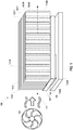
- Fig. 1 is a diagram of an example heat sink 100 with planar fins 110 that include turbulent structures 132.
- the heat sink 100 includes a base 102 defining a first side 104 having a base planar surface, and a second side 106 opposite the first side 104.
- a set of planar fins 110 (e.g., 110-1... N) extend from the base planar surface 106 in parallel disposition relative to each other.
- Each planar fin 110 includes a bottom fin edge 112 coupled to the base planar surface 106 and running parallel to a longitudinal axis 111 of the planar fin 110.
- Each planar fin 110 also is defined by a top fin edge 114 that is opposite the bottom fin edge 112 and running parallel to the longitudinal axis 111 of the planar fin, and is further defined by a leading fin edge 116 extending from the bottom fin 112 edge to the top fin edge 114, and a trailing fin edge 118 opposite the leading fin edge 114 and extending from the bottom fin edge 112 to the top fin edge 114.
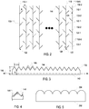
- Fig. 2 is top view of the planar fins 110 with turbulent structures 132.
- Each fin 110 defines a fin body 120 extending from the bottom fin edge 112 to the top fin edge 114 and having a first side 122 defining a first planar surface and second side 124 opposite the first side defining a second planar surface. To avoid congestion in the drawings, like elements for all fins 110 are not labeled.
- each planar fin 110 includes a first set of turbulent structures 132-1 extending from the first planar surface 122, and a second set of turbulent structures 132-2 extending from the second planar surface 134.
- Exterior fin 110-1 includes only a first set of turbulent structures 132-1 on the first planar surface 122.
- exterior fin 110-N includes only a second set of turbulent structures 132-2 on the second planar surface 124.
- exterior fins 110-1 and 110-N have turbulent structures 132 on both of their respective first planar surface 122 and second planar surface 134.
- the turbulent structures 132 are uniformly spaced apart, and each respective set 132-1 and 132-2 are offset from each other so as to not overly reduce airflow that would otherwise result if the sets 132-1 and 132-2 were not offset.
- Fig. 3 is a side perspective of a turbulent structure 132.
- Each turbulent structure 132 defines longitudinal axis 140 and having a first edge 142 that is parallel to the longitudinal axis 140.
- the first edge 142 is connected to the planar surface 122 or 124.
- the turbulent structures 132 are connected at an acute angle A, as shown in Fig. 2 .
- the turbulent structure 132 includes a second edge 144 opposite the first edge 142.
- the second edge as shown in Fig. 2 , is in free space such that air may flow over the second edge 142.
- the second edge 144 defines a periphery 145 (a second edge of which is shown in phantom and offset in Fig.
- each second edge 144 is further shaped such that turbulent flow of a fluid is induced in the fluid flowing over the second edge 144 at at least a predefined flow rate, e.g., at a flow rate induced by a fan 101.
- the periphery 145 varies linearly in distance from the edge 142 from a maximum distance of H to a minimum distance of h, with the relative maximum and minimum spaced apart by a distance d.
- the values of A, H, h and d can be varied to achieve different heat transfer coefficients. Such heat transfer coefficients can be measured empirically, for example.
- Fig. 3 is but one example of a periphery that can be used.
- a turbulent structure 202 with a curved periphery pattern 204 can be used.
- Other periphery patterns can also be used, such as a saw-tooth pattern, a straight tooth pattern, or still other patterns.
- the second edge 144 has a uniform cross section. In other implementations, however, each second edge 144 may include terminal nubs 146 to further increase turbulent flow. As shown in Fig. 4 , the terminal nub 146 is pyramidal in shape; however, a variety of other shapes can be used.
Landscapes
- Engineering & Computer Science (AREA)
- Physics & Mathematics (AREA)
- Thermal Sciences (AREA)
- Microelectronics & Electronic Packaging (AREA)
- Mechanical Engineering (AREA)
- General Engineering & Computer Science (AREA)
- Cooling Or The Like Of Electrical Apparatus (AREA)
- Cooling Or The Like Of Semiconductors Or Solid State Devices (AREA)
Abstract
Description
- This specification relates generally to providing cooling to electronic equipment.
- Electronic devices generate heat through power consumption. Excessive heat generation without sufficient cooling can lead to damage and failure of electronic devices. Electronic devices may be cooled by cooling systems such as heat sinks. Heat sinks are passive heat exchangers that transfer heat from electronic devices to a fluid medium.
- Heat sinks can be used to cool electronic devices, e.g., processors, memories, network devices, and other heat generating devices. In computing systems, heat sinks can be used to cool central processing units (CPUs), graphics processing units (GPUs), tensor processing units (TPU), chipsets, and random access memory (RAM) modules, and other electronic devices.
- A heat sink is a passive heat exchanger that can transfer heat generated by an electronic device to a lower temperature fluid medium, such as air or a liquid coolant. The fluid medium removes and disperses heat from the electronic device. A heat sink can be used to lower or maintain the temperature of the electronic device, preventing the electronic device from overheating.
- The amount of heat that can be removed by a heat sink is dependent on various factors, to include the surface area of the heat sink, the fluid volume and velocity through the heat sink, and the direction of fluid flow through the heat sink. Heat sink performance can be improved by increasing the amount of heat that the heat sink removes from the electronic device. Heat sink performance can also be improved by increasing the rate of heat removal from the electronic device.
- In general, one innovative aspect of the subject matter described in this specification can be embodied in a heat sink including: a base defining a first side having a base planar surface and a second side opposite the first side; and a plurality of planar fins extending from the base planar surface in parallel disposition relative to each other, each planar fin of the plurality of planar fins comprising: a bottom fin edge coupled to the base planar surface and running parallel a longitudinal axis of the planar fin, a top fin edge that is opposite the bottom fin edge and running parallel the longitudinal axis of the planar fin, a leading fin edge extending from the bottom fin edge to the top fin edge, a trailing fin edge opposite the leading fin edge and extending from the bottom fin edge to the top fin edge, a fin body extending from the bottom fin edge to the top fin edge and having a first side defining a first planar surface and second side opposite the first side defining a second planar surface; and a first set of turbulent structures extending from the first planar surface, each turbulent structure in the first set of turbulent structures defining a longitudinal axis and having a first edge that is parallel to the longitudinal axis and connected to the first planar surface and a second edge opposite the first edged and in free space, the second edge defining a periphery that varies in distance from the first edge along the length of the longitudinal axis; and wherein the periphery of each second edge is further shaped such that turbulent flow of a fluid is induced in the fluid flowing over the second edge at at least a predefined flow rate.
- Another innovative aspect of the subject matter described in this specification can be embodied in a planar fin comprising a bottom fin edge coupled to the base planar surface and running parallel a longitudinal axis of the planar fin; a top fin edge that is opposite the bottom fin edge and running parallel the longitudinal axis of the planar fin; a leading fin edge extending from the bottom fin edge to the top fin edge; a trailing fin edge opposite the leading fin edge and extending from the bottom fin edge to the top fin edge; a fin body extending from the bottom fin edge to the top fin edge and having a first side defining a first planar surface and second side opposite the first side defining a second planar surface; and a first set of turbulent structures extending from the first planar surface, each turbulent structure in the first set of turbulent structures defining a longitudinal axis and having a first edge that is parallel to the longitudinal axis and connected to the first planar surface and a second edge opposite the first edged and in free space, the second edge defining a periphery that varies in distance from the first edge along the length of the longitudinal axis; and wherein the periphery of each second edge is further shaped such that turbulent flow of a fluid is induced in the flow flowing over the second edge at at least a predefined flow rate.
- Another innovative aspect of the subject matter described in this specification can be embodied in a heat sink including heat sink comprising: a base defining a first side having a base planar surface and a second side opposite the first side; and a plurality of planar fins extending from the base planar surface in parallel disposition relative to each other, each planar fin of the plurality of planar fins comprising: a bottom fin edge coupled to the base planar surface and running parallel a longitudinal axis of the planar fin; a top fin edge that is opposite the bottom fin edge and running parallel the longitudinal axis of the planar fin; a leading fin edge extending from the bottom fin edge to the top fin edge; a trailing fin edge opposite the leading fin edge and extending from the bottom fin edge to the top fin edge; fin body extending from the bottom fin edge to the top fin edge and having a first side defining a first planar surface and second side opposite the first side defining a second planar surface; and means for inducing turbulent flow extending from the first planar surface and that induce turbulent flow of a fluid flowing over the means at at least a predefined flow rate.
- The details of one or more embodiments of the subject matter of this specification are set forth in the accompanying drawings and the description below. Other features, aspects, and advantages of the subject matter will become apparent from the description, the drawings, and the claims.
-
-
Fig. 1 is a diagram of an example heat sink with planar fins that include turbulent structures. -
Fig. 2 is top view of the planar fins with turbulent structures. -
Fig. 3 is a side view of a turbulent structure. -
Fig. 4 is a perspective view of a turbulent structure with a terminal nub. -
Fig. 5 is a side view of another turbulent structure. - Like reference numbers and designations in the various drawings indicate like elements.
- Heatsink performance is improved when turbulent flow occurs between the fins when the fluid flows at the predefined rate. To induce turbulent flow, the planar fins of the heat sink include a set of turbulent structures. The turbulent structures extend from a first planar surface of the fin, e.g., a first side of the fin. Each turbulent structure in the first set of turbulent structures defines a longitudinal axis and has a first edge that is parallel to the longitudinal axis and connected to the first planar surface. Each turbulent structure also has a second edge opposite the first edge and in free space. The second edge defines a periphery that varies in distance from the first edge along the length of the longitudinal axis. For example, the periphery can be saw tooth shaped, straight tooth shaped, or even curved. The periphery of each second edge is further shaped such that turbulent flow of a fluid is induced in the fluid flowing over the second edge at at least a predefined flow rate.
- Turbulent structures can also be attached to the other side of the heatsink fin and offset from the structures on the first side of the heatsink fin. In this configuration, the turbulent structures extend into the space between heatsinks from both heatsink surfaces. With higher turbulence, the heat sink realizes a higher heat transfer coefficient h that would otherwise be realized with smooth fins. This leads to better convection cooling capabilities. Thus, the principle of this design is to add turbulence enhancement features on the heatsink fins to increase heat transfer coefficient.
- These features and additional features are described in more detail below.
-
Fig. 1 is a diagram of anexample heat sink 100 withplanar fins 110 that includeturbulent structures 132. Theheat sink 100 includes abase 102 defining afirst side 104 having a base planar surface, and asecond side 106 opposite thefirst side 104. A set of planar fins 110 (e.g., 110-1... N) extend from the baseplanar surface 106 in parallel disposition relative to each other. Eachplanar fin 110 includes abottom fin edge 112 coupled to the baseplanar surface 106 and running parallel to alongitudinal axis 111 of theplanar fin 110. Eachplanar fin 110 also is defined by atop fin edge 114 that is opposite thebottom fin edge 112 and running parallel to thelongitudinal axis 111 of the planar fin, and is further defined by a leadingfin edge 116 extending from thebottom fin 112 edge to thetop fin edge 114, and atrailing fin edge 118 opposite the leadingfin edge 114 and extending from thebottom fin edge 112 to thetop fin edge 114. -
Fig. 2 is top view of theplanar fins 110 withturbulent structures 132. Eachfin 110 defines afin body 120 extending from thebottom fin edge 112 to thetop fin edge 114 and having afirst side 122 defining a first planar surface andsecond side 124 opposite the first side defining a second planar surface. To avoid congestion in the drawings, like elements for allfins 110 are not labeled. - In some implementations, except for exterior fins 110-1 and 110-N, each
planar fin 110 includes a first set of turbulent structures 132-1 extending from the firstplanar surface 122, and a second set of turbulent structures 132-2 extending from the second planar surface 134. Exterior fin 110-1, however, includes only a first set of turbulent structures 132-1 on the firstplanar surface 122. Conversely, exterior fin 110-N includes only a second set of turbulent structures 132-2 on the secondplanar surface 124. In other implementations, exterior fins 110-1 and 110-N haveturbulent structures 132 on both of their respective firstplanar surface 122 and second planar surface 134. - The
turbulent structures 132 are uniformly spaced apart, and each respective set 132-1 and 132-2 are offset from each other so as to not overly reduce airflow that would otherwise result if the sets 132-1 and 132-2 were not offset. -
Fig. 3 is a side perspective of aturbulent structure 132. Eachturbulent structure 132 defineslongitudinal axis 140 and having afirst edge 142 that is parallel to thelongitudinal axis 140. Thefirst edge 142 is connected to theplanar surface turbulent structures 132 are connected at an acute angle A, as shown inFig. 2 . Theturbulent structure 132 includes asecond edge 144 opposite thefirst edge 142. The second edge, as shown inFig. 2 , is in free space such that air may flow over thesecond edge 142. Thesecond edge 144 defines a periphery 145 (a second edge of which is shown in phantom and offset inFig. 2 ) that varies in distance from thefirst edge 142 along the length of thelongitudinal axis 140. Theperiphery 145 of eachsecond edge 144 is further shaped such that turbulent flow of a fluid is induced in the fluid flowing over thesecond edge 144 at at least a predefined flow rate, e.g., at a flow rate induced by afan 101. As shown inFig. 3 , theperiphery 145 varies linearly in distance from theedge 142 from a maximum distance of H to a minimum distance of h, with the relative maximum and minimum spaced apart by a distance d. The values of A, H, h and d can be varied to achieve different heat transfer coefficients. Such heat transfer coefficients can be measured empirically, for example. - The triangular shape of
Fig. 3 is but one example of a periphery that can be used. For example, as shown inFig. 5 , aturbulent structure 202 with acurved periphery pattern 204 can be used. Other periphery patterns can also be used, such as a saw-tooth pattern, a straight tooth pattern, or still other patterns. - In some implementations, the
second edge 144 has a uniform cross section. In other implementations, however, eachsecond edge 144 may includeterminal nubs 146 to further increase turbulent flow. As shown inFig. 4 , theterminal nub 146 is pyramidal in shape; however, a variety of other shapes can be used. - While this specification contains many specific implementation details, these should not be construed as limitations on the scope of what may be claimed, but rather as descriptions of features that may be specific to particular embodiments. Certain features that are described in this specification in the context of separate embodiments can also be implemented in combination in a single embodiment. Conversely, various features that are described in the context of a single embodiment can also be implemented in multiple embodiments separately or in any suitable subcombination. Moreover, although features may be described above as acting in certain combinations and even initially claimed as such, one or more features from a claimed combination can in some cases be excised from the combination, and the claimed combination may be directed to a subcombination or variation of a subcombination.
- Similarly, while operations are depicted in the drawings in a particular order, this should not be understood as requiring that such operations be performed in the particular order shown or in sequential order, or that all illustrated operations be performed, to achieve desirable results. In certain circumstances, multitasking and parallel processing may be advantageous. Moreover, the separation of various system modules and components in the embodiments described above should not be understood as requiring such separation in all embodiments, and it should be understood that the described program components and systems can generally be integrated together in a single software product or packaged into multiple software products.
- Particular embodiments of the subject matter have been described. Other embodiments are within the scope of the following claims. For example, the actions recited in the claims can be performed in a different order and still achieve desirable results. As one example, the processes depicted in the accompanying figures do not necessarily require the particular order shown, or sequential order, to achieve desirable results. In some cases, multitasking and parallel processing may be advantageous.
Claims (15)
- A planar fin comprising:a bottom fin edge coupled to the base planar surface and running parallel a longitudinal axis of the planar fin;a top fin edge that is opposite the bottom fin edge and running parallel the longitudinal axis of the planar fin;a leading fin edge extending from the bottom fin edge to the top fin edge;
a trailing fin edge opposite the leading fin edge and extending from the bottom fin edge to the top fin edge;a fin body extending from the bottom fin edge to the top fin edge and having a first side defining a first planar surface and second side opposite the first side defining a second planar surface; anda first set of turbulent structures extending from the first planar surface, each turbulent structure in the first set of turbulent structures defining a longitudinal axis and having a first edge that is parallel to the longitudinal axis and connected to the first planar surface and a second edge opposite the first edged and in free space, the second edge defining a periphery that varies in distance from the first edge along the length of the longitudinal axis; andwherein the periphery of each second edge is further shaped such that turbulent flow of a fluid is induced in the flow flowing over the second edge at at least a predefined flow rate. - The planar fin of claim 1, further including a second set of turbulent structures extending from the second planar surface, each turbulent structure in the second set of turbulent structures defining a longitudinal axis and having a first edge that is parallel to the longitudinal axis and connected to the second planar surface and a second edge that is parallel to the longitudinal axis and opposite the first edged and in free space, the second edge defining a periphery that varies in distance from the first edge along the length of the longitudinal axis, wherein the periphery of each second edge is further shaped such that turbulent flow of a fluid is induced in the fluid flowing over the second edge at at least a predefined flow rate.
- The planar fin of claim 1 or 2, wherein the first set of turbulent structures are connected to the planar fin at respective first positions along the longitudinal axis of the planar fin, and the second set of turbulent structures are attached to the planar fin at respective second positions along the longitudinal axis of the planar fin, and wherein the respective first positions are offset from the respective second positions along the longitudinal axis of the planar fin.
- A heat sink comprising:a base defining a first side having a base planar surface and a second side opposite the first side; anda plurality of planar fins according to one of claims 1 to 3 extending from the base planar surface in parallel disposition relative to each other.
- The planar fin of one of claims 1 to 3 or the heat sink of claim 4, wherein the peripheries of the second edges of the first set of turbulent structures and the second set of turbulent structures define a saw-tooth pattern.
- The planar fin of one of claims 1 to 3 or the heat sink of claim 4, wherein the peripheries of the second edges of the first set of turbulent structures and the second set of turbulent structures define a straight-tooth pattern.
- The planar fin of one of claims 1 to 3 or the heat sink of claim 4, wherein the peripheries of the second edges of the first set of turbulent structures and the second set of turbulent structures define a curved pattern.
- The heat sink of one of claims 4 to 7, wherein each planar fin is attached to a planar surface at an acute angle relative to the planar surface.
- The heat sink of claim 8, wherein the acute angel is measured relative to the trailing fin edge.
- A heat sink comprising:a base defining a first side having a base planar surface and a second side opposite the first side; anda plurality of planar fins extending from the base planar surface in parallel disposition relative to each other, each planar fin of the plurality of planar fins comprising:a bottom fin edge coupled to the base planar surface and running parallel to a longitudinal axis of the planar fin;a top fin edge that is opposite the bottom fin edge and running parallel to the longitudinal axis of the planar fin;a leading fin edge extending from the bottom fin edge to the top fin edge;a trailing fin edge opposite the leading fin edge and extending from the bottom fin edge to the top fin edge;a fin body extending from the bottom fin edge to the top fin edge and having a first side defining a first planar surface and second side opposite the first side defining a second planar surface; andmeans for inducing turbulent flow extending from the first planar surface and that induce turbulent flow of a fluid flowing over the means at at least a predefined flow rate.
- The heat sink of claim 10, wherein the means for inducing turbulent flow defines a saw-tooth pattern.
- The heat sink of claim 10, wherein the means for inducing turbulent flow defines a straight-tooth pattern.
- The heat sink of claim 10, wherein the means for inducing turbulent flow defines a curved pattern.
- The heat sink of one of claims 10 to 13, wherein each planar fin is attached to a planar surface at an acute angle relative to the planar surface.
- The heat sink of claim 14, wherein the acute angel is measured relative to the trailing fin edge.
Priority Applications (1)
| Application Number | Priority Date | Filing Date | Title |
|---|---|---|---|
| EP25152622.4A EP4528801A3 (en) | 2020-04-08 | 2020-10-12 | Heat sink with turbulent structures |
Applications Claiming Priority (1)
| Application Number | Priority Date | Filing Date | Title |
|---|---|---|---|
| US16/843,536 US11039550B1 (en) | 2020-04-08 | 2020-04-08 | Heat sink with turbulent structures |
Related Child Applications (1)
| Application Number | Title | Priority Date | Filing Date |
|---|---|---|---|
| EP25152622.4A Division EP4528801A3 (en) | 2020-04-08 | 2020-10-12 | Heat sink with turbulent structures |
Publications (2)
| Publication Number | Publication Date |
|---|---|
| EP3892950A1 true EP3892950A1 (en) | 2021-10-13 |
| EP3892950B1 EP3892950B1 (en) | 2025-01-22 |
Family
ID=72840330
Family Applications (2)
| Application Number | Title | Priority Date | Filing Date |
|---|---|---|---|
| EP20201240.7A Active EP3892950B1 (en) | 2020-04-08 | 2020-10-12 | Heat sink with turbulent structures |
| EP25152622.4A Pending EP4528801A3 (en) | 2020-04-08 | 2020-10-12 | Heat sink with turbulent structures |
Family Applications After (1)
| Application Number | Title | Priority Date | Filing Date |
|---|---|---|---|
| EP25152622.4A Pending EP4528801A3 (en) | 2020-04-08 | 2020-10-12 | Heat sink with turbulent structures |
Country Status (4)
| Country | Link |
|---|---|
| US (3) | US11039550B1 (en) |
| EP (2) | EP3892950B1 (en) |
| CN (1) | CN113498299B (en) |
| TW (2) | TWI801760B (en) |
Families Citing this family (4)
| Publication number | Priority date | Publication date | Assignee | Title |
|---|---|---|---|---|
| US11039550B1 (en) * | 2020-04-08 | 2021-06-15 | Google Llc | Heat sink with turbulent structures |
| JP2023135729A (en) * | 2022-03-16 | 2023-09-29 | ニデック株式会社 | cooling member |
| JP7777029B2 (en) * | 2022-03-31 | 2025-11-27 | 本田技研工業株式会社 | Water jacket |
| US12459328B2 (en) * | 2022-09-12 | 2025-11-04 | Aptera Motors Corp. | Supplemental aerodynamic heat exchanger for a vehicle |
Citations (5)
| Publication number | Priority date | Publication date | Assignee | Title |
|---|---|---|---|---|
| JPH04291750A (en) * | 1991-03-20 | 1992-10-15 | Hitachi Ltd | Head radiating fin and semiconductor integrated circuit device |
| JPH0846095A (en) * | 1994-08-02 | 1996-02-16 | Hitachi Ltd | Cooling device with variable cooling capacity |
| US20020139515A1 (en) * | 1999-07-02 | 2002-10-03 | Kaveh Azar | Heat sink with textured regions |
| WO2013087140A1 (en) * | 2011-12-16 | 2013-06-20 | Wieland-Werke Ag | Condenser tubes with additional flank structure |
| CN109099750A (en) * | 2018-08-30 | 2018-12-28 | 珠海格力电器股份有限公司 | Heat exchange tube and heat pump unit |
Family Cites Families (77)
| Publication number | Priority date | Publication date | Assignee | Title |
|---|---|---|---|---|
| US974722A (en) * | 1909-10-27 | 1910-11-01 | Hans W Gutermann | Guard for birds. |
| US2359288A (en) * | 1942-07-20 | 1944-10-03 | Young Radiator Co | Turbulence strip for heat exchangers |
| US2800291A (en) * | 1950-10-24 | 1957-07-23 | Stephens Arthur Veryan | Solid boundary surface for contact with a relatively moving fluid medium |
| US3163207A (en) * | 1961-07-26 | 1964-12-29 | Robert T Schultz | Heat dissipating mount for electric components |
| US3265127A (en) * | 1963-10-21 | 1966-08-09 | Ford Motor Co | Heat exchange element |
| DE1501568B2 (en) * | 1966-10-12 | 1971-05-13 | Linde Ag, 6200 Wiesbaden | PLATE HEAT EXCHANGER |
| US3578264A (en) * | 1968-07-09 | 1971-05-11 | Battelle Development Corp | Boundary layer control of flow separation and heat exchange |
| US3741285A (en) * | 1968-07-09 | 1973-06-26 | A Kuethe | Boundary layer control of flow separation and heat exchange |
| US3769959A (en) * | 1972-03-02 | 1973-11-06 | Chicken Unlimited Inc | Heating tube and baffle for deep fat fryers |
| US4549606A (en) * | 1982-09-08 | 1985-10-29 | Kabushiki Kaisha Kobe Seiko Sho | Heat transfer pipe |
| JPS61134042A (en) | 1984-12-04 | 1986-06-21 | Toshiba Corp | Equipment for manufacturing semiconductor device |
| JPH0333070Y2 (en) * | 1985-02-08 | 1991-07-12 | ||
| JPH01204498A (en) * | 1988-02-09 | 1989-08-17 | Fujitsu Ltd | Heat sink for forced cooling |
| US5077601A (en) * | 1988-09-09 | 1991-12-31 | Hitachi, Ltd. | Cooling system for cooling an electronic device and heat radiation fin for use in the cooling system |
| GB2234806A (en) * | 1989-08-09 | 1991-02-13 | Secretary Trade Ind Brit | Heat exchangers |
| JP2788793B2 (en) * | 1991-01-14 | 1998-08-20 | 古河電気工業株式会社 | Heat transfer tube |
| US5224538A (en) * | 1991-11-01 | 1993-07-06 | Jacoby John H | Dimpled heat transfer surface and method of making same |
| US5361828A (en) * | 1993-02-17 | 1994-11-08 | General Electric Company | Scaled heat transfer surface with protruding ramp surface turbulators |
| CH687831A5 (en) * | 1993-04-08 | 1997-02-28 | Asea Brown Boveri | Premix burner. |
| EP0623786B1 (en) * | 1993-04-08 | 1997-05-21 | Asea Brown Boveri Ag | Combustion chamber |
| JP3236137B2 (en) * | 1993-07-30 | 2001-12-10 | 富士通株式会社 | Semiconductor element cooling device |
| CA2144350A1 (en) * | 1995-03-10 | 1996-09-11 | John Waring | Drag reducing arrangement for athlete |
| US5887280A (en) * | 1995-03-10 | 1999-03-30 | Waring; John | Wearable article for athlete with vortex generators to reduce form drag |
| US5957194A (en) * | 1996-06-27 | 1999-09-28 | Advanced Thermal Solutions, Inc. | Plate fin heat exchanger having fluid control means |
| JP3352362B2 (en) * | 1997-07-14 | 2002-12-03 | 三菱電機株式会社 | Heat sink |
| KR19990012680A (en) * | 1997-07-30 | 1999-02-25 | 박병재 | Radiator fin for radiator |
| US5901641A (en) * | 1998-11-02 | 1999-05-11 | Afc Enterprises, Inc. | Baffle for deep fryer heat exchanger |
| JP3431004B2 (en) * | 2000-01-14 | 2003-07-28 | 松下電器産業株式会社 | Heat sink and cooling device using the same |
| US6170566B1 (en) * | 1999-12-22 | 2001-01-09 | Visteon Global Technologies, Inc. | High performance louvered fin for a heat exchanger |
| NL1014151C2 (en) * | 2000-01-21 | 2001-07-24 | Inalfa Ind Bv | Open roof construction for a vehicle. |
| US6269864B1 (en) * | 2000-02-18 | 2001-08-07 | Intel Corporation | Parallel-plate/pin-fin hybrid copper heat sink for cooling high-powered microprocessors |
| JP2001332666A (en) * | 2000-05-24 | 2001-11-30 | Nakamura Seisakusho Kk | Cylindrical radiator and method of forming the same |
| JP2001345585A (en) * | 2000-06-01 | 2001-12-14 | Hitachi Kokusai Electric Inc | Radiation fin |
| EP1164269B1 (en) * | 2000-06-15 | 2007-08-22 | BorgWarner Inc. | Cooling fin arrangement |
| DE10058574B4 (en) * | 2000-11-24 | 2005-09-15 | Danfoss Drives A/S | Cooling unit for power semiconductors |
| US6418020B1 (en) * | 2001-03-30 | 2002-07-09 | Advanced Thermal Technologies | Heat dissipation device with ribbed fin plates |
| JP3443112B2 (en) * | 2001-07-09 | 2003-09-02 | 株式会社東芝 | Cooling device and electronic device equipped with the cooling device |
| JP2003078081A (en) * | 2001-09-05 | 2003-03-14 | Nakamura Mfg Co Ltd | Method of forming radiator |
| DE10153512A1 (en) * | 2001-10-30 | 2003-05-15 | Siemens Ag | Cooling element for modern high-efficiency semiconductor devices has cooling fins arranged on flat side of baseplate, and which have end faces on inflow and outflow sides constructed to enhance flow dynamics |
| US6590770B1 (en) | 2002-03-14 | 2003-07-08 | Modine Manufacturing Company | Serpentine, slit fin heat sink device |
| CN100449246C (en) * | 2002-12-02 | 2009-01-07 | Lg电子株式会社 | Heat exchangers for ventilation systems |
| US6845812B2 (en) | 2002-12-20 | 2005-01-25 | Motorola, Inc. | Heatsink with multiple, selectable fin densities |
| US6886627B2 (en) | 2003-06-27 | 2005-05-03 | Intel Corporation | Radial heat sink with helical shaped fins |
| JP4462877B2 (en) * | 2003-08-29 | 2010-05-12 | 古河スカイ株式会社 | Heat sink with louver |
| US7096678B2 (en) * | 2004-09-01 | 2006-08-29 | Gelcore Llc | Method and apparatus for increasing natural convection efficiency in long heat sinks |
| US20060102325A1 (en) | 2004-11-17 | 2006-05-18 | Detech Technology Co., Ltd. | Guiding fin heat sink |
| US7289322B2 (en) * | 2005-10-24 | 2007-10-30 | Fu Zhun Precision Industry (Shen Zhen) Co., Ltd. | Heat sink |
| CN1997274B (en) * | 2006-01-06 | 2011-11-09 | 富准精密工业(深圳)有限公司 | Radiator |
| TWI293861B (en) * | 2006-01-13 | 2008-02-21 | Foxconn Tech Co Ltd | Heat sink |
| US7474528B1 (en) * | 2006-04-10 | 2009-01-06 | Sun Microsystems, Inc. | Configurable flow control air baffle |
| US20070240868A1 (en) * | 2006-04-17 | 2007-10-18 | Chaun-Choung Technology Corp. | Air-guiding structure for heat-dissipating fin |
| US7568518B2 (en) * | 2006-07-21 | 2009-08-04 | Furui Precise Component (Kunshan) Co., Ltd. | Heat sink |
| US7760506B1 (en) * | 2007-06-06 | 2010-07-20 | Hewlett-Packard Development Company, L.P. | Electronic components, systems and apparatus with air flow devices |
| JP2009147107A (en) * | 2007-12-14 | 2009-07-02 | Toyota Motor Corp | Cooling fin and method of manufacturing cooling fin |
| US8537548B2 (en) * | 2008-01-29 | 2013-09-17 | Intel Corporation | Method, apparatus and computer system for vortex generator enhanced cooling |
| CN100547339C (en) * | 2008-03-12 | 2009-10-07 | 江苏萃隆精密铜管股份有限公司 | A kind of enhanced heat transfer tube and its manufacturing method |
| US20090321046A1 (en) * | 2008-06-30 | 2009-12-31 | Alcatel-Lucent Technologies Inc. | Flow diverters to enhance heat sink performance |
| CN101420841B (en) * | 2008-10-23 | 2012-06-27 | 旭丽电子(广州)有限公司 | Heat radiating mechanism |
| US20100170657A1 (en) | 2009-01-06 | 2010-07-08 | United Technologies Corporation | Integrated blower diffuser-fin heat sink |
| CN201476662U (en) * | 2009-04-30 | 2010-05-19 | 昆山市德准精密模具有限公司 | Radiating fin, radiating fin group and heat sink |
| US20110079370A1 (en) | 2009-07-17 | 2011-04-07 | Textron Inc. | Non-Uniform Height And Density Fin Design For Heat Sink |
| CN201749868U (en) * | 2010-05-19 | 2011-02-16 | 深圳市瑞丰光电子股份有限公司 | Liquid cooling LED packaging device |
| CN101949662B (en) * | 2010-09-28 | 2012-08-15 | 烟台恒辉铜业有限公司 | Novel high-efficiency heat exchange pipe for condenser of electric refrigeration unit |
| CN102121805A (en) * | 2011-04-07 | 2011-07-13 | 金龙精密铜管集团股份有限公司 | Enhanced heat transfer tube used for falling film evaporator |
| ITTO20130055A1 (en) * | 2013-01-23 | 2014-07-24 | Denso Thermal Systems Spa | FIN STRUCTURE FOR HEAT EXCHANGER FOR AUTOMOTIVE APPLICATIONS, IN PARTICULAR FOR AGRICULTURAL AND CONSTRUCTION MACHINES. |
| PL2969715T3 (en) * | 2013-03-13 | 2021-07-19 | Andrew Bacon | Improvements in the fuel efficiency of road vehicles |
| US9217353B2 (en) * | 2013-04-03 | 2015-12-22 | Caterpillar Inc. | Mixer for fluid injection system |
| US10139172B2 (en) * | 2014-08-28 | 2018-11-27 | Mahle International Gmbh | Heat exchanger fin retention feature |
| KR102392605B1 (en) * | 2015-09-25 | 2022-05-02 | 한온시스템 주식회사 | Wavy fin |
| JP6662696B2 (en) * | 2016-04-21 | 2020-03-11 | リンナイ株式会社 | Turbulence generator |
| CN206640935U (en) * | 2017-04-14 | 2017-11-14 | 青岛唯科电子有限公司 | Fin slices radiator |
| CN109097500A (en) * | 2018-08-13 | 2018-12-28 | 兴义市黔农居养种植农民专业合作社 | A kind of brown sugar preparation method of rapid crystallization |
| CN109883238A (en) * | 2019-03-08 | 2019-06-14 | 西安交通大学 | A kind of plate fin type heat exchanger core and its fin structure |
| CN209945100U (en) * | 2019-05-28 | 2020-01-14 | 江苏胜翔轻合金科技有限公司 | Radiating fin for plate-fin heat exchanger |
| US11039550B1 (en) * | 2020-04-08 | 2021-06-15 | Google Llc | Heat sink with turbulent structures |
| FI130775B1 (en) * | 2020-11-13 | 2024-03-12 | Thermal Channel Tech Oy | Heat sink as well as apparatus and method of producing the same |
| CN113380737B (en) * | 2021-04-28 | 2024-05-07 | 西安交通大学 | A Y-shaped immersed capillary microchannel enhanced heat dissipation structure and a manufacturing method thereof |
-
2020
- 2020-04-08 US US16/843,536 patent/US11039550B1/en active Active
- 2020-10-05 TW TW109134341A patent/TWI801760B/en active
- 2020-10-05 TW TW112110212A patent/TWI829560B/en active
- 2020-10-12 EP EP20201240.7A patent/EP3892950B1/en active Active
- 2020-10-12 EP EP25152622.4A patent/EP4528801A3/en active Pending
- 2020-10-16 CN CN202011110972.8A patent/CN113498299B/en active Active
-
2021
- 2021-05-12 US US17/318,900 patent/US11574850B2/en active Active
-
2023
- 2023-01-04 US US18/149,990 patent/US12255117B2/en active Active
Patent Citations (5)
| Publication number | Priority date | Publication date | Assignee | Title |
|---|---|---|---|---|
| JPH04291750A (en) * | 1991-03-20 | 1992-10-15 | Hitachi Ltd | Head radiating fin and semiconductor integrated circuit device |
| JPH0846095A (en) * | 1994-08-02 | 1996-02-16 | Hitachi Ltd | Cooling device with variable cooling capacity |
| US20020139515A1 (en) * | 1999-07-02 | 2002-10-03 | Kaveh Azar | Heat sink with textured regions |
| WO2013087140A1 (en) * | 2011-12-16 | 2013-06-20 | Wieland-Werke Ag | Condenser tubes with additional flank structure |
| CN109099750A (en) * | 2018-08-30 | 2018-12-28 | 珠海格力电器股份有限公司 | Heat exchange tube and heat pump unit |
Also Published As
| Publication number | Publication date |
|---|---|
| US20210320046A1 (en) | 2021-10-14 |
| TWI801760B (en) | 2023-05-11 |
| US11574850B2 (en) | 2023-02-07 |
| EP3892950B1 (en) | 2025-01-22 |
| US12255117B2 (en) | 2025-03-18 |
| US11039550B1 (en) | 2021-06-15 |
| TWI829560B (en) | 2024-01-11 |
| EP4528801A3 (en) | 2025-06-11 |
| EP4528801A2 (en) | 2025-03-26 |
| US20230154821A1 (en) | 2023-05-18 |
| CN113498299A (en) | 2021-10-12 |
| CN113498299B (en) | 2025-02-18 |
| TW202331183A (en) | 2023-08-01 |
| TW202138736A (en) | 2021-10-16 |
Similar Documents
| Publication | Publication Date | Title |
|---|---|---|
| US12255117B2 (en) | Heat sink with turbulent structures | |
| US20220316822A1 (en) | Heat dissipation device and fin structure | |
| TWI749730B (en) | Fluid diverting heat sink | |
| CN114556040B (en) | Protective covers for integrated circuit heat exchangers | |
| US20150250075A1 (en) | Cooler and electronic device | |
| TWI765606B (en) | Liquid-cooling heat dissipation structure | |
| JPH01204498A (en) | Heat sink for forced cooling | |
| JP6549721B2 (en) | Heat sink, method of manufacturing heat sink and method of using heat sink | |
| HK40060913A (en) | Heat sink with turbulent structures | |
| US20190033930A1 (en) | Cooling device for use in heat dissipation associated with electronic components | |
| CN210247322U (en) | Radiator, radiating system with radiator and medical equipment | |
| JP2019047028A (en) | Cooling device and electronic device | |
| US20130014921A1 (en) | Air flow guiding structure | |
| RU2758039C1 (en) | Radiator for cooling the electronic component | |
| CN207623914U (en) | Heat sink structure | |
| Joel et al. | Study of effect of fin geometry on cooling process of computer microchips through modelling and simulation | |
| HK40053572A (en) | Fluid diverting heat sink | |
| CN108260327B (en) | Interlayer water cooling drainage structure with flow disturbing group | |
| CN107396613B (en) | A radiator for electronic components with a circular arc section with regularly changing fin distances | |
| TWI845153B (en) | A heat exchanger for an electronic component of a server | |
| KR200315458Y1 (en) | Heat dissipation device with liquid coolant | |
| CN216795614U (en) | A finned heat sink | |
| Wang et al. | The Study of the Cooling Effect of the Internal Loop Air-Liquid Hybrid Cooling System (ILALHCS) on Edge Servers | |
| CN210425752U (en) | A cooling tooth liquid cold plate | |
| WO2023287384A1 (en) | A heat sink with tree-structured fins |
Legal Events
| Date | Code | Title | Description |
|---|---|---|---|
| PUAI | Public reference made under article 153(3) epc to a published international application that has entered the european phase |
Free format text: ORIGINAL CODE: 0009012 |
|
| STAA | Information on the status of an ep patent application or granted ep patent |
Free format text: STATUS: THE APPLICATION HAS BEEN PUBLISHED |
|
| AK | Designated contracting states |
Kind code of ref document: A1 Designated state(s): AL AT BE BG CH CY CZ DE DK EE ES FI FR GB GR HR HU IE IS IT LI LT LU LV MC MK MT NL NO PL PT RO RS SE SI SK SM TR |
|
| STAA | Information on the status of an ep patent application or granted ep patent |
Free format text: STATUS: REQUEST FOR EXAMINATION WAS MADE |
|
| 17P | Request for examination filed |
Effective date: 20220228 |
|
| RBV | Designated contracting states (corrected) |
Designated state(s): AL AT BE BG CH CY CZ DE DK EE ES FI FR GB GR HR HU IE IS IT LI LT LU LV MC MK MT NL NO PL PT RO RS SE SI SK SM TR |
|
| STAA | Information on the status of an ep patent application or granted ep patent |
Free format text: STATUS: EXAMINATION IS IN PROGRESS |
|
| 17Q | First examination report despatched |
Effective date: 20230926 |
|
| GRAP | Despatch of communication of intention to grant a patent |
Free format text: ORIGINAL CODE: EPIDOSNIGR1 |
|
| STAA | Information on the status of an ep patent application or granted ep patent |
Free format text: STATUS: GRANT OF PATENT IS INTENDED |
|
| INTG | Intention to grant announced |
Effective date: 20240816 |
|
| GRAS | Grant fee paid |
Free format text: ORIGINAL CODE: EPIDOSNIGR3 |
|
| GRAA | (expected) grant |
Free format text: ORIGINAL CODE: 0009210 |
|
| STAA | Information on the status of an ep patent application or granted ep patent |
Free format text: STATUS: THE PATENT HAS BEEN GRANTED |
|
| AK | Designated contracting states |
Kind code of ref document: B1 Designated state(s): AL AT BE BG CH CY CZ DE DK EE ES FI FR GB GR HR HU IE IS IT LI LT LU LV MC MK MT NL NO PL PT RO RS SE SI SK SM TR |
|
| P01 | Opt-out of the competence of the unified patent court (upc) registered |
Free format text: CASE NUMBER: APP_66548/2024 Effective date: 20241216 |
|
| REG | Reference to a national code |
Ref country code: GB Ref legal event code: FG4D |
|
| REG | Reference to a national code |
Ref country code: CH Ref legal event code: EP |
|
| REG | Reference to a national code |
Ref country code: IE Ref legal event code: FG4D |
|
| REG | Reference to a national code |
Ref country code: DE Ref legal event code: R096 Ref document number: 602020045081 Country of ref document: DE |
|
| REG | Reference to a national code |
Ref country code: NL Ref legal event code: FP |
|
| PG25 | Lapsed in a contracting state [announced via postgrant information from national office to epo] |
Ref country code: RS Free format text: LAPSE BECAUSE OF FAILURE TO SUBMIT A TRANSLATION OF THE DESCRIPTION OR TO PAY THE FEE WITHIN THE PRESCRIBED TIME-LIMIT Effective date: 20250422 |
|
| PG25 | Lapsed in a contracting state [announced via postgrant information from national office to epo] |
Ref country code: FI Free format text: LAPSE BECAUSE OF FAILURE TO SUBMIT A TRANSLATION OF THE DESCRIPTION OR TO PAY THE FEE WITHIN THE PRESCRIBED TIME-LIMIT Effective date: 20250122 |
|
| PG25 | Lapsed in a contracting state [announced via postgrant information from national office to epo] |
Ref country code: PL Free format text: LAPSE BECAUSE OF FAILURE TO SUBMIT A TRANSLATION OF THE DESCRIPTION OR TO PAY THE FEE WITHIN THE PRESCRIBED TIME-LIMIT Effective date: 20250122 |
|
| PG25 | Lapsed in a contracting state [announced via postgrant information from national office to epo] |
Ref country code: ES Free format text: LAPSE BECAUSE OF FAILURE TO SUBMIT A TRANSLATION OF THE DESCRIPTION OR TO PAY THE FEE WITHIN THE PRESCRIBED TIME-LIMIT Effective date: 20250122 |
|
| REG | Reference to a national code |
Ref country code: LT Ref legal event code: MG9D |
|
| PG25 | Lapsed in a contracting state [announced via postgrant information from national office to epo] |
Ref country code: NO Free format text: LAPSE BECAUSE OF FAILURE TO SUBMIT A TRANSLATION OF THE DESCRIPTION OR TO PAY THE FEE WITHIN THE PRESCRIBED TIME-LIMIT Effective date: 20250422 Ref country code: IS Free format text: LAPSE BECAUSE OF FAILURE TO SUBMIT A TRANSLATION OF THE DESCRIPTION OR TO PAY THE FEE WITHIN THE PRESCRIBED TIME-LIMIT Effective date: 20250522 |
|
| REG | Reference to a national code |
Ref country code: AT Ref legal event code: MK05 Ref document number: 1761753 Country of ref document: AT Kind code of ref document: T Effective date: 20250122 |
|
| PG25 | Lapsed in a contracting state [announced via postgrant information from national office to epo] |
Ref country code: HR Free format text: LAPSE BECAUSE OF FAILURE TO SUBMIT A TRANSLATION OF THE DESCRIPTION OR TO PAY THE FEE WITHIN THE PRESCRIBED TIME-LIMIT Effective date: 20250122 |
|
| PG25 | Lapsed in a contracting state [announced via postgrant information from national office to epo] |
Ref country code: LV Free format text: LAPSE BECAUSE OF FAILURE TO SUBMIT A TRANSLATION OF THE DESCRIPTION OR TO PAY THE FEE WITHIN THE PRESCRIBED TIME-LIMIT Effective date: 20250122 Ref country code: PT Free format text: LAPSE BECAUSE OF FAILURE TO SUBMIT A TRANSLATION OF THE DESCRIPTION OR TO PAY THE FEE WITHIN THE PRESCRIBED TIME-LIMIT Effective date: 20250522 |
|
| PG25 | Lapsed in a contracting state [announced via postgrant information from national office to epo] |
Ref country code: BG Free format text: LAPSE BECAUSE OF FAILURE TO SUBMIT A TRANSLATION OF THE DESCRIPTION OR TO PAY THE FEE WITHIN THE PRESCRIBED TIME-LIMIT Effective date: 20250122 Ref country code: GR Free format text: LAPSE BECAUSE OF FAILURE TO SUBMIT A TRANSLATION OF THE DESCRIPTION OR TO PAY THE FEE WITHIN THE PRESCRIBED TIME-LIMIT Effective date: 20250423 |
|
| PG25 | Lapsed in a contracting state [announced via postgrant information from national office to epo] |
Ref country code: AT Free format text: LAPSE BECAUSE OF FAILURE TO SUBMIT A TRANSLATION OF THE DESCRIPTION OR TO PAY THE FEE WITHIN THE PRESCRIBED TIME-LIMIT Effective date: 20250122 |
|
| PG25 | Lapsed in a contracting state [announced via postgrant information from national office to epo] |
Ref country code: SE Free format text: LAPSE BECAUSE OF FAILURE TO SUBMIT A TRANSLATION OF THE DESCRIPTION OR TO PAY THE FEE WITHIN THE PRESCRIBED TIME-LIMIT Effective date: 20250122 |
|
| PG25 | Lapsed in a contracting state [announced via postgrant information from national office to epo] |
Ref country code: SM Free format text: LAPSE BECAUSE OF FAILURE TO SUBMIT A TRANSLATION OF THE DESCRIPTION OR TO PAY THE FEE WITHIN THE PRESCRIBED TIME-LIMIT Effective date: 20250122 |
|
| PG25 | Lapsed in a contracting state [announced via postgrant information from national office to epo] |
Ref country code: DK Free format text: LAPSE BECAUSE OF FAILURE TO SUBMIT A TRANSLATION OF THE DESCRIPTION OR TO PAY THE FEE WITHIN THE PRESCRIBED TIME-LIMIT Effective date: 20250122 |
|
| PG25 | Lapsed in a contracting state [announced via postgrant information from national office to epo] |
Ref country code: IT Free format text: LAPSE BECAUSE OF FAILURE TO SUBMIT A TRANSLATION OF THE DESCRIPTION OR TO PAY THE FEE WITHIN THE PRESCRIBED TIME-LIMIT Effective date: 20250122 |
|
| PG25 | Lapsed in a contracting state [announced via postgrant information from national office to epo] |
Ref country code: EE Free format text: LAPSE BECAUSE OF FAILURE TO SUBMIT A TRANSLATION OF THE DESCRIPTION OR TO PAY THE FEE WITHIN THE PRESCRIBED TIME-LIMIT Effective date: 20250122 Ref country code: CZ Free format text: LAPSE BECAUSE OF FAILURE TO SUBMIT A TRANSLATION OF THE DESCRIPTION OR TO PAY THE FEE WITHIN THE PRESCRIBED TIME-LIMIT Effective date: 20250122 |
|
| REG | Reference to a national code |
Ref country code: DE Ref legal event code: R097 Ref document number: 602020045081 Country of ref document: DE |
|
| PG25 | Lapsed in a contracting state [announced via postgrant information from national office to epo] |
Ref country code: RO Free format text: LAPSE BECAUSE OF FAILURE TO SUBMIT A TRANSLATION OF THE DESCRIPTION OR TO PAY THE FEE WITHIN THE PRESCRIBED TIME-LIMIT Effective date: 20250122 |
|
| PG25 | Lapsed in a contracting state [announced via postgrant information from national office to epo] |
Ref country code: SK Free format text: LAPSE BECAUSE OF FAILURE TO SUBMIT A TRANSLATION OF THE DESCRIPTION OR TO PAY THE FEE WITHIN THE PRESCRIBED TIME-LIMIT Effective date: 20250122 |
|
| PGFP | Annual fee paid to national office [announced via postgrant information from national office to epo] |
Ref country code: NL Payment date: 20251026 Year of fee payment: 6 |
|
| PLBE | No opposition filed within time limit |
Free format text: ORIGINAL CODE: 0009261 |
|
| STAA | Information on the status of an ep patent application or granted ep patent |
Free format text: STATUS: NO OPPOSITION FILED WITHIN TIME LIMIT |
|
| 26N | No opposition filed |
Effective date: 20251023 |
|
| PGFP | Annual fee paid to national office [announced via postgrant information from national office to epo] |
Ref country code: DE Payment date: 20251029 Year of fee payment: 6 |
|
| PGFP | Annual fee paid to national office [announced via postgrant information from national office to epo] |
Ref country code: GB Payment date: 20251027 Year of fee payment: 6 |
|
| PGFP | Annual fee paid to national office [announced via postgrant information from national office to epo] |
Ref country code: FR Payment date: 20251027 Year of fee payment: 6 |