EP3891324B1 - Verfahren zum betreiben einer kräuselvorrichtung und kräuselvorrichtung - Google Patents
Verfahren zum betreiben einer kräuselvorrichtung und kräuselvorrichtung Download PDFInfo
- Publication number
- EP3891324B1 EP3891324B1 EP19783269.4A EP19783269A EP3891324B1 EP 3891324 B1 EP3891324 B1 EP 3891324B1 EP 19783269 A EP19783269 A EP 19783269A EP 3891324 B1 EP3891324 B1 EP 3891324B1
- Authority
- EP
- European Patent Office
- Prior art keywords
- pressure
- clamping
- pressure plates
- rollers
- actuators
- Prior art date
- Legal status (The legal status is an assumption and is not a legal conclusion. Google has not performed a legal analysis and makes no representation as to the accuracy of the status listed.)
- Active
Links
Images



Classifications
-
- D—TEXTILES; PAPER
- D02—YARNS; MECHANICAL FINISHING OF YARNS OR ROPES; WARPING OR BEAMING
- D02G—CRIMPING OR CURLING FIBRES, FILAMENTS, THREADS, OR YARNS; YARNS OR THREADS
- D02G1/00—Producing crimped or curled fibres, filaments, yarns, or threads, giving them latent characteristics
- D02G1/12—Producing crimped or curled fibres, filaments, yarns, or threads, giving them latent characteristics using stuffer boxes
-
- D—TEXTILES; PAPER
- D02—YARNS; MECHANICAL FINISHING OF YARNS OR ROPES; WARPING OR BEAMING
- D02G—CRIMPING OR CURLING FIBRES, FILAMENTS, THREADS, OR YARNS; YARNS OR THREADS
- D02G1/00—Producing crimped or curled fibres, filaments, yarns, or threads, giving them latent characteristics
- D02G1/12—Producing crimped or curled fibres, filaments, yarns, or threads, giving them latent characteristics using stuffer boxes
- D02G1/125—Producing crimped or curled fibres, filaments, yarns, or threads, giving them latent characteristics using stuffer boxes including means for monitoring or controlling yarn processing
Definitions
- the invention relates to a method for operating a crimping device according to the preamble of claim 1 and a crimping device for crimping a fiber strand according to the preamble of claim 6.
- Such crimping devices are used in particular in the production of staple fibers.
- the fibers of the fiber strand are crimped.
- the fibers of the fiber strand are guided through a roller gap that is formed between two driven rollers.
- the roller gap is followed by a so-called compression chamber in which the fibers of the fiber strand are conveyed.
- the roller gap is sealed at the front of the rollers by a pressure plate. It is usual to press the pressure plates against the front of the rollers with a contact force. Due to the relative movement between the rollers and the pressure plates, wear and tear inevitably occurs, as well as metal abrasion, which is absorbed by the fibers and is therefore undesirable.
- the DE 195 37 958 A A crimping device is known in which the printing plates are held to the front sides of the rollers by means of a pressure actuator and a superimposed rotary drive causes the printing plates to rotate. Despite this rotation of the printing plates, wear is possible due to the printing plates being under pressure on the front sides of the rollers. In addition, the relative movements between the printing plates and the front sides of the rollers, heat development can be observed, which leads to an increase in the temperature of the adjacent fiber strands. The friction required for wear and heating is not significantly reduced by the rotation of the pressure plates, since the speed vectors of the pressure plates and the front sides of the rollers are not aligned.
- crimping devices are also known in the state of the art, in which a defined sealing gap is set between the front sides of the rollers and the pressure plate.
- DE 102 43 203 A1 A crimping device is known in which the pressure plates are arranged on the front plates of the rollers via a side plate with a predefined sealing gap.
- the sealing gap can be set using a fixing agent.
- preset sealing gaps between a pressure plate and the front sides of the rollers generally have the disadvantage that individual filaments of the fiber strands are pressed into the sealing gap. In this respect, wear between the pressure plates and the rollers is avoided, but with the disadvantage that fibers are pressed from the roller gap into the sealing gap.
- the publication DE 36 21 479 A1 The invention relates to a stuffer box crimping device for crimping synthetic yarn sheets.
- the aim is to seal a pair of rollers at the sides using side elements of the stuffer box and pressure disks that are constantly pressed against the rollers.
- the contact pressure is regulated depending on the deflection of feeler elements that can be formed by the side parts of the stuffer box.
- the invention has the particular advantage that no contact force acts between the printing plates and the front sides of the rollers when the crimping device is in operation.
- the printing plates are immediately fixed in a contact position in which there is almost no sealing gap by a clamp.
- the printing plates are briefly pressed against the front sides of the rollers at the start of a process and are held in place by a clamping force after reaching a contact position.
- the crimping device has a separate clamp actuator for clamping the printing plates for each printing plate, which can be controlled together with the pressure actuators by at least one control unit. This means that after activating the clamp actuators, which fix the printing plates in their respective contact positions, the pressure actuators can be deactivated. During operation, the printing plates therefore no longer need to be pressed against the front sides of the rollers.
- the pressure plates are clamped with a radially acting clamping force in such a way that the pressure plates remain in the contact position during operation.
- the pressure forces generated by the fiber strand inside the roller gap are absorbed by the clamping forces on the pressure plates.
- each of the pressure plates is connected to a rotary drive and carries out a superimposed rotation relative to the relevant front side of the rollers in the contact position is particularly advantageous. This allows for an equalization of the load on the pressure plate. reached.
- the crimping device has rotary drives that are coupled to the printing plates so that the printing plates can rotate relative to the front sides of the rollers.
- the preferred process variant is one in which the printing plates are pressed axially onto the front sides of the rollers using a pneumatically generated pressure force. No high forces are required, since the pressure forces in the roller gap that occur during operation are absorbed solely by the clamping forces acting on the printing plates. The pressure force is only used to set the gap-free printing plate position before the start of the process.
- the printing plates are preferably held radially in the contact position with a hydraulically generated clamping force. This ensures that the printing plates remain in their contact positions during operation of the crimping device.
- the sealing gaps that may form during operation depend exclusively on the material of the components and their modulus of elasticity. In extreme cases, these may only be a few micrometers.
- the adjustment of the pressure plates and the fixing of the pressure plates can preferably be carried out by a support piston that rests on the front side of one of the pressure plates.
- the forces for adjusting the pressure plates and for clamping the pressure plates can thus advantageously be generated by the pressure actuator and the clamping actuator directly on the support piston.
- the support pistons each have a rotatable shaft section which is connected to the pressure plates in a rotationally fixed manner and which is coupled to the rotary drives.
- the support pistons can be connected to the shaft sections by a bearing which enables the pressure forces to be transmitted.
- the crimping device according to the invention is particularly advantageous in the development in which one of the pressure actuators acts axially and one of the clamping actuators acts radially on a support piston that rests on a pressure plate.
- the pressure actuator and the clamping actuator can thus be advantageously integrated into a structural unit that is assigned to the pressure plates with a support piston.
- the pressure actuator advantageously has a compressed air supply and the clamping actuator has a hydraulic supply.
- the variant in which the pressure actuator and the clamping actuator are integrated in one housing is particularly compact. This means that the unit can also be operated advantageously in the harsh environment of a fiber line.
- the method according to the invention for operating a crimping device and the crimping device according to the invention thus offer the particular advantage that the fiber strands can be crimped and guided with high uniformity even in the edge region of the roller gap.
- FIG. 1 shows the embodiment in a front view and in Fig. 2 a side view is shown. Only the components of a crimping device that are essential to the invention are shown here.
- the crimping device has two driven rollers 1.1 and 1.2, which are arranged in a machine frame (not shown here) and are driven by at least one motor (also not shown here).
- the rollers 1.1 and 1.2 form a roller gap 2 between them.
- a compression chamber 3 is assigned to the rolls 1.1 and 1.2 on an outlet side of the roll gap 2.
- the compression chamber 3 is delimited on both front sides of the rolls 1.1 and 1.2 by a side plate 4.1 and 4.2.
- the base plate 3.1 and the top plate 3.2 are directly associated with the circumference of the rolls 1.1 and 1.2 on the inlet side of the stuffer box 3.
- the side plates 4.1 and 4.2 each have a pressure plate 5.1 and 5.2 in the area of the roller gap 2.
- the pressure plate 5.1 is embedded in the side plate 4.1 and is designed to be axially movable.
- the pressure plate 5.2 is accordingly embedded in the side plate 4.2.
- the side plates 4.1 and 4.2 each have a recess 6.1 and 6.2 for this purpose.
- a support piston 7.1 and 7.2 is assigned to each of the pressure plates 5.1 and 5.2.
- the support pistons 7.1 and 7.2 penetrate the side plates 4.1 and 4.2 and rest on the front side of the pressure plates 5.1 and 5.2.
- a pressure actuator 8.1 and a clamping actuator 9.1 act on a projecting end of the support piston 7.1.
- the pressure actuator 8.1 and the clamping actuator 9.1 are connected to a control unit 11.
- a second pressure actuator 8.2 and a second clamping actuator 9.2 act on the free projecting end of the support piston 7.2.
- the pressure actuator 8.2 and the clamping actuator 9.2 are also coupled to a control unit 11.
- the pressure actuators 8.1 and 8.2 as well as the clamp actuators 9.1 and 9.2 are in Fig. 1 only shown schematically.
- electrical, pneumatic or hydraulic pressure actuators can be used, which generate an axially acting pressure force on the support pistons 7.1 and 7.2.
- the clamping actuators 9.1 and 9.2 could be formed by electrical, pneumatic or hydraulic clamping elements, which generate a radially acting clamping force on the circumference of the support pistons 7.1 and 7.2.
- the pressure plates 5.1 and 5.2 are initially axially displaced synchronously by activating the pressure actuators 8.1 and 8.2 by the control unit 11 and are guided with a pressing force to the front sides 10.1 and 10.2 of the rollers 1.1 and 1.2.
- the clamping actuators 9.1 and 9.2 are activated via the control unit 11 so that the support pistons 7.1 and 7.2 are fixed in their current position by a clamping force on the circumference.
- the pressure plates 5.1 and 5.2 are thus held in their contact position by clamping on the front sides 10.1 and 10.2 of the rollers 1.1 and 1.2.
- the pressure actuators 8.1 and 8.2 are deactivated so that no contact forces are applied and the pressure plates 5.1 and 5.2 remain in their contact position without contact force.
- fiber strands are now fed to the rollers 1.1 and 1.2.
- the fiber strands are pulled through the rollers 1.1 and 1.2 into the roller gap 2 and guided into the adjacent compression chamber 3.
- This creates high operating pressures within the roller gap, which act against the pressure plates 5.1 and 5.2. In this respect, these pressure forces are absorbed by the clamping forces on the support pistons 7.1 and 7.2. No sealing gaps are created.
- the pressure actuators 8.1 and 8.2 as well as the clamping actuators 9.1 and 9.2 can also be advantageously controlled by separate control units, which are in Fig. 1 shown in dashed lines and marked with the reference symbols 11.1 and 11.2. This means that the adjustment of the pressure plates 5.1 and 5.2 and the clamping of the pressure plates 5.1 and 5.2 on both front sides of the rollers 1.1 and 1.2 can be carried out independently of one another.
- connection of the clamp actuators 9.1 and 9.2 and the pressure actuators 8.1 and 8.2 to the support pistons 7.1 and 7.2 is also exemplary. Depending on the design of the pressure actuators and clamp actuators, these could also act directly on the pressure plates and, for example, be partially integrated into the side plates.
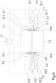
- FIG. 3 schematically shows a cross-sectional view of a possible embodiment of the crimping device in a detail.
- the pressure actuator 8.1 and the clamping actuator 9.1 are integrated in a housing 12.
- a support piston 7.1 is guided in a housing bore 20.
- the housing bore 20 is closed at one end and connected to a compressed air supply connection 13 formed on the housing 12.
- An air chamber 15 is formed below the support piston 7.1 within the housing bore 20.
- a return spring 18 is clamped inside between the support piston 7.1 and the housing 12.
- a clamping bush 17 is held within the housing 12 in a recess 21 of the housing bore 20 between two seals 19.
- the seals 19 limit the recess 21 and act between the housing 12 and the support piston 7.1.
- a pressure chamber 16 is formed on the circumference of the clamping bush 17, which communicates with a hydraulic supply connection 14 in the housing 12.
- the support piston 7.1 has a projecting end which rests against an end face of the pressure plate 5.1.
- the pressure actuator 8.1 is activated via the compressed air supply connection 13.
- compressed air is fed into the air chamber 15, which presses the support piston 7.1 against the pressure plate 5.1, so that the pressure plate 5.1 is guided in a contact position on the front sides 10.1 and 10.2 of the rollers 1.1 and 1.2.
- the clamping actuator 9.1 is activated via the hydraulic supply connection 14. For this purpose, a hydraulic fluid under high pressure is fed into the pressure chamber 16, which clamps the support piston 7.1 via the clamping bushing 17. As soon as the support piston 7.1 is clamped by the clamping actuator 9.1, the pressure actuator 8.1 is deactivated by depressurizing the air supply connection 13. The pressure plate 5.1 in the side plate 4.1 is now ready for operation.
- Fig. 3 Only one of the pressure plates 4.1 is shown.
- the pressure actuators 8.2 and clamping actuators 9.2 associated with the pressure plate 4.2 are identical to the embodiment shown according to Fig. 3 Synchronous or asynchronous control of the pressure actuators 8.1 and 8.2 and clamp actuators 9.1 and 9.2 is possible.
- FIG. 4 Another embodiment of the crimping device according to the invention is shown schematically in a front view.
- the embodiment according to Fig. 4 is essentially identical to the embodiment according to Fig. 1 and 2 , so that only the differences are explained below to avoid repetition and otherwise reference is made to the above description.
- the pressure plates 5.1 and 5.2 located on the front sides of the rollers 1.1 and 1.2 are separate Assigned to rotary drives 22.1 and 22.2.
- the rotary drives 22.1 and 22.2 are connected to a control device 11.
- the control device is also connected to the pressure actuators 8.1 and 8.2 and to the clamping actuators 9.1 and 9.2 in order to guide and fix the pressure plates 5.1 and 5.2 in a respective installation position at the start of the process.
- the rotary drives 22.1 and 22.2 are activated via the control device 11 in order to rotate the pressure plates 5.1 and 5.2 relative to the front sides 10.1 and 10.2 of the rollers 1.1 and 1.2.
- the support pistons 7.1 and 7.2 which interact with the pressure actuators 8.1 and 8.2 and the clamping actuators 9.1 and 9.2, are designed in two parts.
- Each of the support pistons 7.1 and 7.2 has a shaft section 23.1 and 23.2 at the end facing the pressure plates 5.1 and 5.2, which is rotatably held on the support pistons 7.1 and 7.2.
- the rotary drives 22.1 and 22.2 act on the shaft sections 23.1 and 23.2 of the support pistons 7.1 and 7.2.
- the shaft sections 23.1 and 23.2 are connected in a rotationally fixed manner to the respective pressure plate 5.1 and 5.2, which is preferably designed to be form-fitting.
- the Fig. 4 The embodiment shown thus has the particular advantage that the position of the pressure plates 5.1 and 5.2 changes relative to the front sides 10.1 and 10.2 of the rollers 1.1 and 1.2. This results in an equalization of the load on the pressure plates 5.1 and 5.2.
- the rotary drives 22.1 and 22.2 can be implemented using electrical, hydraulic or pneumatic means.
- FIG. 5 Another embodiment of the crimping device according to the invention is shown schematically in a detail view.
- the in Fig. 5 The embodiment shown is identical to that in Fig. 3 shown embodiment, so that reference is first made to the above description and otherwise only the differences are explained.
- the components with the same function have of course been given identical reference numerals.
- the pressure actuators and clamp actuators are each integrated into a structural unit.
- the structural unit acts on a support piston 7.1, which is guided in a housing 12.
- a shaft section 23.1 is formed on the projecting end of the support piston 7.1, which is held on the support piston 7.1 via a bearing 27.
- the bearing 27 between the shaft section 23.1 and the support piston 7.1 is designed in such a way that an axial force is transmitted unhindered to the shaft section 23.1.
- the shaft section 23.1 is coupled with its free end in a form-fitting and rotationally fixed manner to the pressure plate 5.1.
- a worm gear 24 is provided, which is connected to a gearing on the shaft section 23.1 via a worm shaft 25.
- the worm shaft 25 is driven in rotation by a drive 26.
- the drive 26 is only shown schematically here and could, for example, be implemented by electrical, pneumatic or hydraulic means.
- a drive of the shaft section 23.1 can already be implemented hydraulically in such a way that the worm shaft 25 is driven in an oscillating manner via a hydraulic actuator.
- the connection between the shaft section 23.1 and the worm gear 24 has a freewheel, so that the rotary movement of the worm shaft 25 is only transmitted to the shaft section 23.1 in one direction of rotation.
- the function is identical to the above-mentioned embodiment according to Fig. 4 .
- the drive 26 is activated by the control unit (not shown here).
- the pressure plate 5.1 carries out a relative movement to the rollers 1.1 and 1.2.
- the crimping device according to the invention is preferably used in a plant for staple fiber production, by means of which very high-quality staple fiber can be produced due to the advantages of the tightness of the sealing gaps without frictional wear.
Landscapes
- Engineering & Computer Science (AREA)
- Mechanical Engineering (AREA)
- Textile Engineering (AREA)
- Yarns And Mechanical Finishing Of Yarns Or Ropes (AREA)
- Press Drives And Press Lines (AREA)
Description
- Die Erfindung betrifft ein Verfahren zum Betreiben einer Kräuselvorrichtung gemäß dem Oberbegriff des Anspruchs 1 sowie eine Kräuselvorrichtung zum Kräuseln eines Faserstranges gemäß dem Oberbegriff des Anspruchs 6.
- Derartige Kräuselvorrichtungen finden insbesondere Anwendungen in der Herstellung von Stapelfasern. Vor dem Schneiden eines Faserstranges erhalten die Fasern des Faserstranges eine Kräuselung. Hierzu werden die Fasern des Faserstranges durch einen Walzenspalt geführt, der zwischen zwei angetriebenen Walzen ausgebildet ist. Dem Walzenspalt folgt eine sogenannte Stauchkammer, in welchem die Fasern des Faserstranges gefördert werden. Um ein seitliches an den Stirnseiten der Walzen aus dem Walzenspalt austreten der Fasern zu verhindern, wird der Walzenspalt an den Stirnseiten der Walzen durch jeweils eine Druckplatte abgedichtet. Dabei ist es üblich, die Druckplatten jeweils an die Stirnseiten der Walzen mit einer Anpresskraft zu drücken. Aufgrund der Relativbewegung zwischen den Walzen und den Druckplatten kommt es zwangsläufig zu Verschleißerscheinungen sowie zu einem Metallabrieb, der von den Fasern aufgenommen wird und somit unerwünscht ist.
- Um einen derartigen Metallabrieb zu vermeiden, ist aus der
DE 195 37 958 A eine Kräuselvorrichtung bekannt, bei welcher die Druckplatten mittels eines Druckaktors an die Stirnseiten der Walzen gehalten werden und wobei ein überlagerter Drehantrieb zu einer Drehung der Druckplatten führt. Trotz dieser Rotation der Druckplatten ist ein Verschleiß durch die mit Druckbelastung an den Stirnseiten der Walzen anliegenden Druckplatten möglich. Zudem sind durch die Relativbewegungen zwischen den Druckplatten und den Stirnseiten der Walzen Wärmeentwicklungen zu beobachten, die zu einer Temperaturerhöhung der angrenzenden Faserstränge führt. Die Reibung, welche für den Verschleiß und die Erwärmung erforderlich ist, wird auch durch die Rotation der Druckplatten nicht wesentlich verringert, da die Geschwindigkeitsvektoren der Druckplatten und der Stirnseiten der Walzen nicht gleichgerichtet sind. - Grundsätzlich sind auch andere Kräuselvorrichtungen im Stand der Technik bekannt, bei welchem zwischen den Stirnseiten der Walzen und der Druckplatte ein definierter Dichtspalt eingestellt wird. So ist beispielsweise aus der
DE 102 43 203 A1 eine Kräuselvorrichtung bekannt, bei welcher die Druckplatten über jeweils eine Seitenplatte mit einem vordefinierten Dichtspalt an den Stirnplatten der Walzen angeordnet sind. Der Dichtspalt lässt sich hierbei über ein Fixiermittel einstellen. Derartige voreingestellte Dichtspalte zwischen einer Druckplatte und den Stirnseiten der Walzen besitzen jedoch grundsätzlich den Nachteil, dass einzelne Filamente der Faserstränge in die Dichtspalte gedrückt werden. Insoweit wird zwar ein Verschleiß zwischen den Druckplatten und den Walzen vermieden, jedoch mit dem Nachteil, dass Fasern aus dem Walzenspalt in die Dichtspalte gedrückt werden. - Die Druckschrift
DE 36 21 479 A1 hat eine Stauchkammerkräuselvorrichtung zum Kräuseln von synthetischen Fadenscharen zum Gegenstand. Dabei ist vorgesehen, ein Walzenpaar zu den Seiten hin durch seitliche Elemente der Stauchkammer und ständig an die Walzen angepresste Druckscheiben abzudichten. Ein Anpressdruck wird dabei in Abhängigkeit der Durchbiegung von Tastorganen, die durch die Seitenteile der Stauchkammer gebildet sein können, reguliert. - Weitere Vorrichtungen der bekannten Art sind in den Dokumenten
DE 195 37 958 C1 undUS 3 800 373 A offenbart. - Es ist nun Aufgabe der Erfindung, ein Verfahren zum Betreiben einer Kräuselvorrichtung sowie eine gattungsgemäße Kräuselvorrichtung zu schaffen mittels welchem, bzw. welcher die Kräuselung eines Faserstranges in einer solchen Art und Weise erfolgt, dass zwischen den Walzen und den Druckplatten möglichst kein Verschleiß auftritt und möglichst keine Dichtspalte entstehen.
- Diese Aufgabe wird erfindungsgemäß durch ein Verfahren zum Betreiben einer Kräuselvorrichtung mit den Merkmalen nach Anspruch 1 und durch eine Kräuselvorrichtung mit den Merkmalen nach Anspruch 6 gelöst.
- Vorteilhafte Weiterbildungen der Erfindung sind durch die jeweiligen Merkmale und Merkmalskombinationen der Unteransprüche definiert.
- Die Erfindung besitzt den besonderen Vorteil, dass im Betrieb der Kräuselvorrichtung keine Anpresskraft zwischen den Druckplatten und den Stirnseiten der Walzen wirkt. Die Druckplatten werden unmittelbar in einer Anlagestellung, in welcher nahezu kein Dichtspalt vorhanden ist, durch eine Klemmung fixiert. Hierzu werden die Druckplatten bei einem Prozessbeginn kurzzeitig an die Stirnseiten der Walzen gedrückt und nach Erreichen einer Anlagestellung durch eine Klemmkraft gehalten. Die Kräuselvorrichtung weist hierzu pro Druckplatte jeweils einen separaten Klemmaktor zum Klemmen der Druckplatten auf, der gemeinsam mit den Druckaktoren durch zumindest ein Steuergerät steuerbar ist. So lässt sich nach Aktivierung der Klemmaktoren, die die Druckplatten in ihren jeweiligen Anlagestellungen festsetzen, die Druckaktoren deaktivieren. Im Betrieb entfällt somit das Andrücken der Druckplatten an die Stirnseiten der Walzen.
- Die Druckplatten werden hierzu mit einer radial wirkenden Klemmkraft derart geklemmt, dass die Druckplatten im Betrieb in der Anlagestellung verbleiben. Insoweit sind die im Innern des Walzenspaltes durch den Faserstrang erzeugten Druckkräfte durch die Klemmkräfte an den Druckplatten aufzunehmen.
- Um die Flächen der Druckplatten gleichmäßig zur Abdichtung der Dichtspalte gegenüber den Stirnseiten der Walzen nutzen zu können, ist die Verfahrensvariante besonders vorteilhaft, bei welcher jede der Druckplatten mit jeweils einem Drehantrieb verbunden ist und eine überlagerte Rotation relativ zu der betreffenden Stirnseite der Walzen in der Anlagestellung ausführt. So wird eine Vergleichsmäßigung der Belastung an der Druckplatte erreicht.
- Die Kräuselvorrichtung weist hierzu Drehantriebe auf, die mit den Druckplatten gekoppelt sind, so dass die Druckplatten relativ zu den Stirnseiten der Walzen rotieren können.
- Um die Druckplatten in die jeweiligen Anlagestellungen zu führen, ist die Verfahrensvariante bevorzugt ausgeführt, bei welcher die Druckplatten mit einer pneumatisch erzeugten Druckkraft axial an die Stirnseiten der Walzen gedrückt werden. Es sind keine hohen Kräfte erforderlich, da die im Betrieb auftretenden Druckkräfte im Walzenspalt allein durch die an den Druckplatten wirkenden Klemmkräfte abgefangen werden. Die Druckkraft dient nur zur Einstellung der spaltfreien Druckplattenposition vor Prozessbeginn.
- Um relativ hohe Klemmkräfte erzeugen zu können, werden die Druckplatten bevorzugt mit einer hydraulisch erzeugten Klemmkraft radial in der Anlagestellung gehalten. Somit ist sichergestellt, dass die Druckplatten in ihren Anlagestellungen während des Betriebes der Kräuselvorrichtung verharren. Die sich möglicherweise im Betrieb ausbildenden Dichtspalte sind ausschließlich von dem Material der Bauteile und deren E-Modul abhängig. Diese dürfen im Extremfall nur wenige Mikrometer betragen.
- Das Einstellen der Druckplatten und die Fixierung der Druckplatten lässt sich bevorzugt durch einen Stützkolben realisieren, der an einer Stirnseite einer der Druckplatten anliegt. Die Kräfte zum Einstellen der Druckplatten und zum Klemmen der Druckplatten können somit vorteilhaft durch den Druckaktor und den Klemmaktor unmittelbar an dem Stützkolben erzeugt werden.
- Um trotz der Klemmung eine Rotation der Druckplatten zu ermöglichen, ist die Weiterbildung der Kräuselvorrichtung bevorzugt ausgeführt, bei welcher die Stützkolben jeweils einen drehbaren Wellenabschnitt aufweisen, die drehfest mit den Druckplatten verbunden sind und die mit den Drehantrieben gekoppelt sind. So können die Stützkolben beispielweise durch eine Lagerung mit den Wellabschnitten verbunden sein, die eine Übertragung der Druckkräfte ermöglicht.
- Insoweit ist die erfindungsgemäße Kräuselvorrichtung in der Weiterbildung besonders vorteilhaft, bei welcher einer der Druckaktoren axial und einer der Klemmaktoren radial auf einen Stützkolben einwirken, der an einer Druckplatte anliegt. Somit lassen sich der Druckaktor und der Klemmaktor vorteilhaft in eine Baueinheit integrieren, die mit einem Stützkolben den Druckplatten zugeordnet ist.
- Der Druckaktor weist hierbei vorteilhaft eine Druckluftzuführung und der Klemmaktor eine Hydraulikzuführung auf.
- Besonders kompakt ist die Variante, bei welcher der Druckaktor und der Klemmaktor in einem Gehäuse integriert ausgebildet sind. Somit lässt sich die Baueinheit auch vorteilhaft in der rauen Umgebung einer Faserstraße betreiben.
- Das erfindungsgemäße Verfahren zum Betreiben einer Kräuselvorrichtung und die erfindungsgemäße Kräuselvorrichtung bieten somit den besonderen Vorteil, dass die Faserstränge mit hoher Gleichmäßigkeit auch im Randbereich des Walzenspaltes kräuselbar und führbar sind.
- Das erfindungsgemäße Verfahren zum Betreiben einer Kräuselvorrichtung wird nachfolgend anhand eines Ausführungsbeispiels der erfindungsgemäßen Kräuselvorrichtung unter Bezug auf die beigefügten Figuren näher erläutert.
- Es stellen dar:
- Fig. 1
- schematisch eine Vorderansicht eines ersten Ausführungsbeispiel einer erfindungsgemäßen Kräuselvorrichtung
- Fig. 2
- schematisch eine Seitenansicht des Ausführungsbeispiels aus
Fig. 1 - Fig. 3
- schematisch eine Ausschnittdarstellung eines weiteren Ausführungsbeispiels der erfindungsgemäßen Kräuselvorrichtung
- Fig.4
- schematisch eine Vorderansicht eines weiteren Ausführungsbeispiel einer erfindungsgemäßen Kräuselvorrichtung
- Fig. 5
- schematisch eine Ausschnittdarstellung eines weiteren Ausführungsbeispiel der erfindungsgemäßen Kräuselvorrichtung
- In den
Fig. 1 und2 ist ein erstes Ausführungsbeispiel der erfindungsgemäßen Kräuselvorrichtung in mehreren Ansichten schematisch dargestellt.Fig. 1 zeigt das Ausführungsbeispiel in eine Vorderansicht und inFig. 2 ist eine Seitenansicht gezeigt. Hierbei sind nur die für die Erfindung wesentlichen Bauteile einer Kräuselvorrichtung dargestellt. - Die Kräuselvorrichtung weist zwei angetriebene Walzen 1.1 und 1.2 auf, die in einem hier nicht dargestellten Maschinengestell angeordnet sind und durch zumindest einem Motor (hier ebenfalls nicht dargestellt) angetrieben sind. Die Walzen 1.1 und 1.2 bilden zwischen sich einen Walzenspalt 2.
- Wie in der
Fig. 2 dargestellt ist, ist den Walzen 1.1 und 1.2 auf einer Auslassseite des Walzenspaltes 2 eine Stauchkammer 3 zugeordnet. Die Stauchkammer 3 wird zu beiden Stirnseiten der Walzen 1.1 und 1.2 durch jeweils eine Seitenplatte 4.1 und 4.2 begrenzt. Zwischen den Seitenplatten 4.1 und 4.2 ist eine Bodenplatte 3.1 und eine Oberplatte 3.2 angeordnet, die zwischen sich den Kammereinlass der Stauchkammer 3 parallel zum Walzenspalt bilden. Die Bodenplatte 3.1 und die Oberplatte 3.2 sind unmittelbar dem Umfang der Walzen 1.1 und 1.2 auf der Einlaufseite der Stauchkammer 3 zugeordnet. - Wie insbesondere aus der Darstellung in
Fig. 1 hervorgeht, weisen die Seitenplatten 4.1 und 4.2 im Bereich des Walzenspaltes 2 jeweils eine Druckplatte 5.1 und 5.2 auf. Die Druckplatte 5.1 ist in der Seitenplatte 4.1 eingelassen und axial beweglich ausgeführt. Dementsprechend ist die Druckplatte 5.2 in der Seitenplatte 4.2 eingebettet. Die Seitenplatten 4.1 und 4.2 weisen hierzu jeweils eine Eindrehung 6.1 und 6.2 auf. Zur axialen Verstellung der Druckplatten 5.1 und 5.2 ist jeder der Druckplatte 5.1 und 5.2 jeweils ein Stützkolben 7.1 und 7.2 zugeordnet. Die Stützkolben 7.1 und7.2 durchdringen dabei die Seitenplatten 4.1 und 4.2 und liegen stirnseitig an den Druckplatten 5.1 und 5.2 an. - An einem auskragenden Ende des Stützkolbens 7.1 wirkt ein Druckaktor 8.1 und ein Klemmaktor 9.1. Der Druckaktor 8.1 und der Klemmaktor 9.1 sind mit einem Steuergerät 11 verbunden.
- Auf der gegenüberliegenden Seite des Walzenspaltes wirkt an dem freien auskragenden Ende des Stützkolbens 7.2 ein zweiter Druckaktor 8.2 und ein zweiter Klemmaktor 9.2. Der Druckaktor 8.2 und der Klemmaktor 9.2 sind ebenfalls mit einem Steuergerät 11 gekoppelt.
- Die Druckaktoren 8.1 und 8.2 sowie die Klemmaktoren 9.1 und 9.2 sind in
Fig. 1 nur schematisch dargestellt. Für die Druckaktoren 8.1 und 8.2 können elektrisch, pneumatisch oder hydraulische Druckaktoren verwendet werden, die eine axial wirkende Andrückkraft auf die Stützkolben 7.1 und 7.2 erzeugen. Dementsprechend könnten die Klemmaktoren 9.1 und 9.2 durch elektrische, pneumatische oder hydraulische Klemmelemente gebildet sein, die eine radial wirkende Klemmkraft am Umfang der Stützkolben 7.1 und 7.2 erzeugen. - Zur Inbetriebnahme der in
Fig. 1 und2 dargestellten Kräuselvorrichtung werden die Druckplatten 5.1 und 5.2 zunächst durch Aktivierung der Druckaktoren 8.1 und 8.2 durch das Steuergerät 11 synchron axial verschoben und mit einer Andrückkraft an die Stirnseiten 10.1 und 10.2 der Walzen 1.1 und 1.2 geführt. Sobald die Druckplatten 5.1 und 5.2 jeweils Anlagestellung erreicht haben, wird über das Steuergerät 11 die Klemmaktoren 9.1 und 9.2 aktiviert, so dass die Stützkolben 7.1 und 7.2 in ihrer momentanen Position durch jeweils eine Klemmkraft am Umfang fixiert werden. Somit sind die Druckplatten 5.1 und 5.2 durch Klemmung in ihrer Anlagestellung an den Stirnseiten 10.1 und 10.2 der Walzen 1.1 und 1.2 gehalten. Die Druckaktoren 8.1 und 8.2 werden deaktiviert, so dass keine Anpresskräfte wirken, und die Druckplatten 5.1 und 5.2 in ihrer Anlagestellung ohne Anpresskraft verharren. Im Betrieb werden nun Faserstränge den Walzen 1.1 und 1.2 zugeführt. Die Faserstränge werden durch die Walzen 1.1 und 1.2 in den Walzenspalt 2 gezogen und in die angrenzende Stauchkammer 3 geführt. Dabei entstehen hohe Betriebsdrücke innerhalb des Walzenspaltes, die gegen die Druckplatten 5.1 und 5.2 wirken. Insoweit werden diese Druckkräfte von den Klemmkräften an den Stützkolben 7.1 und 7.2 abgefangen. Hierbei entstehen keine Dichtspalte. - Bei dem in
Fig. 1 schematisch dargestellten Kräuselvorrichtung können die Druckaktoren 8.1 und 8.2 sowie die Klemmaktoren 9.1 und 9.2 auch vorteilhaft durch separate Steuergeräte gesteuert werden, die inFig. 1 gestrichelt dargestellt und mit dem Bezugszeichen 11.1 und 11.2 gekennzeichnet sind. Somit lässt sich die Einstellung der Druckplatten 5.1 und 5.2 und das Klemmen der Druckplatten 5.1 und 5.2 an beiden Stirnseiten der Walzen 1.1 und 1.2 unabhängig voneinander ausführen. - Ebenso ist die Anbindung der Klemmaktoren 9.1 und 9.2 und der Druckaktoren 8.1 und 8.2 an die Stützkolben 7.1 und 7.2 beispielhaft. So könnten je nach Ausführung der Druckaktoren und Klemmaktoren auch diese unmittelbar direkt auf die Druckplatten einwirken und beispielsweise teilweise in den Seitenplatten integriert sein.
- In der Praxis hat sich jedoch bewährt, den Druckaktor und den Klemmaktor zu einer Baueinheit zu integrieren, um eine möglichst kompakte Bauweise an der Kräuselvorrichtung zu erhalten. Hierzu ist in
Fig. 3 schematisch eine Querschnittsansicht eines möglichen Ausführungsbeispiels der Kräuselvorrichtung in einem Ausschnitt dargestellt. Bei dem inFig. 3 gezeigten Ausführungsbeispiel sind der Druckaktor 8.1 und der Klemmaktor 9.1 in einem Gehäuse 12 integriert. In dem Gehäuse 12 ist ein Stützkolben 7.1 in einer Gehäusebohrung 20 geführt. Die Gehäusebohrung 20 ist an einem Ende verschlossen und mit einem am Gehäuse 12 ausgebildeten Druckluftzufuhranschluss 13 verbunden. Unterhalb des Stützkolbens 7.1 ist innerhalb der Gehäusebohrung 20 eine Luftkammer 15 ausgebildet. Im Innern ist zwischen dem Stützkolben 7.1 und dem Gehäuse 12 eine Rückholfeder 18 eingespannt. - Am Umfang des Stützkolbens 7.1 ist innerhalb des Gehäuses 12 eine Klemmbuchse 17 in einer Aussparung 21 der Gehäusebohrung 20 zwischen zwei Dichtungen 19 gehalten. Die Dichtungen 19 begrenzen die Aussparung 21 und wirken zwischen dem Gehäuse 12 und dem Stützkolben 7.1. Am Umfang der Klemmbuchse 17 ist eine Druckkammer 16 ausgebildet, die mit einem Hydraulikzuführanschluss 14 im Gehäuse 12 kommuniziert.
- Der Stützkolben 7.1 weist ein auskragendes Ende auf, das an einer Stirnfläche der Druckplatte 5.1 anliegt.
- Bei dem in
Fig. 3 dargestellten Ausführungsbeispiel wird der Druckaktor 8.1 über den Druckluftzufuhranschluss 13 aktiviert. Hierzu wird eine Druckluft in die Luftkammer 15 geführt, die den Stützkolben 7.1 gegen die Druckplatte 5.1 drückt, so dass die Druckplatte 5.1 in einer Anlagestellung an den Stirnseiten 10.1 und 10.2 der Walzen 1.1 und 1.2 geführt wird. - Der Klemmaktor 9.1 wird über den Hydraulikzufuhranschluss 14 aktiviert. Hierzu wird eine Hydraulikflüssigkeit unter hohem Druck in die Drucckammer 16 geleitet, die über die Klemmbuchse 17 zu einer Klemmung des Stützkolbens 7.1 führt. Sobald der Stützkolben 7.1 durch den Klemmaktor 9.1 geklemmt ist, wird der Druckaktor 8.1 deaktiviert, in dem der Luftzufuhranschluss 13 drucklos gemacht wird. Nun ist die Druckplatte 5.1 in der Seitenplatten 4.1 betriebsbereit.
- In der
Fig. 3 ist lediglich eine der Druckplatten 4.1 dargestellt. Vorzugsweise sind die der Druckplatte 4.2 zugeordneten Druckaktoren 8.2 und Klemmaktoren 9.2 identisch zu dem gezeigten Ausführungsbeispiel nachFig. 3 ausgeführt. Hierbei ist eine synchrone oder asynchrone Steuerung der Druckaktoren 8.1 und 8.2 und Klemmaktoren 9.1 und 9.2 möglich. - In der
Fig. 4 ist ein weiteres Ausführungsbeispiel der erfindungsgemäßen Kräuselvorrichtung in einer Vorderansicht schematisch dargestellt. Das Ausführungsbeispiel nachFig. 4 ist im Wesentlichen identisch zu dem Ausführungsbeispiel nachFig. 1 und2 , so dass nachfolgend nur die Unterschiede erläutert werden, um Wiederholungen zu vermeiden und ansonsten Bezug zu der vorgenannten Beschreibung genommen wird. - Bei dem in
Fig. 4 dargestellten Ausführungsbeispiel sind den an den Stirnseiten der Walten 1.1 und 1.2 anliegenden Druckplatten 5.1 und 5.2 separate Drehantriebe 22.1 und 22.2 zugeordnet. Die Drehantriebe 22.1 und 22.2 sind mit einer Steuereinrichtung 11 verbunden. Die Steuereinrichtung ist auch mit den Druckaktoren 8.1 und 8.2 sowie mit den Klemmaktoren 9.1 und 9.2 verbunden, um die Druckplatten 5.1 und 5.2 bei Prozessbeginn in eine jeweilige Anlagestellung zu führen und zu fixieren. Sobald die Druckplatten 5.1 und 5.2 in der Anlagenstellung fixiert sind, wird über das Steuergerät 11 die Drehantriebe 22.1 und 22.2 aktiviert, um die Druckplatten 5.1 und 5.2 relativ zu den Stirnseiten 10.1 und 10.2 der Walzen 1.1 und 1.2 zu rotieren. - Um die Druckplatten 5.1 und 5.2 zur Drehbewegung anzutreiben, sind die Stützkolben 7.1 und 7.2, die mit den Druckaktoren 8.1 und 8.2 und den Klemmaktoren 9.1 und 9.2 zusammenwirken, zweiteilig ausgeführt. So weist jeder der Stützkolben 7.1 und 7.2 an dem zu den Druckplatten 5.1 und 5.2 gewandten Ende einen Wellenabschnitt 23.1 und 23.2 auf, der drehbar an den Stützkolben 7.1 und 7.2 gehalten ist. Insoweit wirken die Drehantriebe 22.1 und 22.2 auf die Wellenabschnitte 23.1 und 23.2 der Stützkolben 7.1 und 7.2 ein. Die Wellenabschnitte 23.1 und 23.2 sind mit der jeweiligen Druckplatte 5.1 und 5.2 drehfest verbunden, die vorzugsweise formschlüssig ausgeführt ist.
- Das in
Fig. 4 dargestellte Ausführungsbeispiel besitzt somit den besonderen Vorteil, dass sich die Lage der Druckplatten 5.1 und 5.2 relativ zu den Stirnseiten 10.1 und 10.2 der Walzen 1.1 und 1.2 relativ verändert. Damit wird eine Vergleichmäßigung der Belastung der Druckplatten 5.1 und 5.2 erreicht. Die Drehantriebe 22.1 und 22.2 können durch elektrische, hydraulische oder pneumatische Mittel ausgeführt sein. - In der
Fig. 5 ist ein weiteres Ausführungsbeispiel der erfindungsgemäße Kräuselvorrichtung schematisch in einer Ausschnittdarstellung gezeigt. Das inFig. 5 dargestellte Ausführungsbeispiel ist identisch zu dem inFig. 3 gezeigten Ausführungsbeispiel, so dass zunächst Bezug zu der vorgenannten Beschreibung genommen wird und ansonsten nur die Unterschiede erläutert werden. Die Bauteile gleicher Funktion haben selbstverständlich identische Bezugszeichen erhalten. - Bei dem in
Fig. 5 dargestellten Ausführungsbeispiel sind die Druckaktoren und Klemmaktoren jeweils zu einer Baueinheit integriert. Hierbei wirkt die Baueinheit auf einen Stützkoblen 7.1, der in ein Gehäuse 12 geführt ist. An dem auskragenden Ende des Stützkolbens 7.1 ist ein Wellenabschnitt 23.1 ausgebildet, der über eine Lagerung 27 an dem Stützkolben 7.1 gehalten ist. Die Lagerung 27 zwischen dem Wellenabschnitt 23.1 und dem Stützkolben 7.1 ist derart ausgebildet, dass eine axiale Kraft ungehindert auf den Wellenabschnitt 23.1 übertragen wird. Der Wellenabschnitt 23.1 mit seinem freien Ende formschlüssig und drehfest mit der Druckplatte 5.1 gekoppelt. - Um den Wellenabschnitt 23.1 und damit die Druckplatte 5.1 zu rotieren, ist ein Schneckengetriebe 24 vorgesehen, das über eine Schneckenwelle 25 mit einer Verzahnung an dem Wellenabschnitt 23.1 verbunden ist. Die Schneckenwelle 25 wird durch einen Antrieb 26 rotierend angetrieben. Der Antrieb 26 ist hier nur schematisch dargestellt und könnte beispielsweise durch elektrische, pneumatische oder hydraulische Mittel ausgeführt sein. So lässt sich beispielsweise bereits ein Antrieb des Wellenabschnittes 23.1 derart hydraulisch realisieren, in dem die Schneckenwelle 25 über einen Hydraulikaktor oszillierend angetrieben wird. Die Verbindung zwischen dem Wellenabschnitt 23.1 und dem Schneckengetriebe 24 weist dabei einen Freilauf auf, so dass die Drehbewegung der Schneckenwelle 25 nur in eine Drehrichtung auf den Wellenabschnitt 23.1 übertragen wird.
- Die Funktion ist hierbei identisch zu dem vorgenannten Ausführungsbeispiel nach
Fig. 4 . Sobald die Druckplatte 5.1 durch den Druckaktor und Klemmaktor in seiner Anlagestellung an den Stirnseiten 10.1 und 10.2 der Walzen 1.1 und 1.2 positioniert und fixiert ist, wird der Antrieb 26 durch das hier nicht dargestellte Steuergerät aktiviert. Insoweit führt die Druckplatte 5.1 eine Relativbewegung zu den Walzen 1.1 und 1.2 aus. - Die erfindungsgemäße Kräuselvorrichtung wird vorzugsweise in einer Anlage zur Stapelfaserproduktion verwendet, mittels welcher aufgrund der Vorzüge der Dichtheit der Dichtspalte ohne Reibverschleiß sehr hochwertige Stapelfaser herstellbar sind.
Claims (14)
- Verfahren zum Betreiben einer Kräuselvorrichtung mit zwei angetriebenen Walzen, durch welche ein Faserstrang durch einen Walzenspalt in eine Stauchkammer gefördert wird und bei welchem der Walzenspalt an den Stirnseiten der Walzen durch Druckplatten abgedichtet wird, dadurch gekennzeichnet, dass die Druckplatten bei einem Prozessbeginn kurzeitig aktiv an die Stirnseiten der Walzen gedrückt werden und nach Erreichen einer Anlagestellung durch jeweils eine Klemmkraft gehalten werden.
- Verfahren nach Anspruch 1, dadurch gekennzeichnet, dass jede der Druckplatten mit einer radial wirkenden Klemmkraft derart geklemmt werden, dass die Druckplatte im Betrieb in der Anlagestellung verbleibt.
- Verfahren nach Anspruch 1 oder 2, dadurch gekennzeichnet, dass jede der Druckplatten mit jeweils einem Drehantrieb verbunden ist und eine überlagerte Rotation relativ zu der betreffenden Stirnseite der Walzen in der Anlagestellung ausführt.
- Verfahren nach einem der Ansprüche 1 bis 3, dadurch gekennzeichnet, dass jede der Druckplatten mit einer pneumatisch erzeugten Druckkraft axial an die Stirnseiten der Walzen gedrückt werden.
- Verfahren nach einem der Ansprüche 1 bis 4, dadurch gekennzeichnet, dass jede der Druckplatten mit einer hydraulisch erzeugten Klemmkraft radial in der Anlagestellung geklemmt werden.
- Verfahren nach einem der Ansprüche 1 bis 54, dadurch gekennzeichnet, dass einer der Druckaktoren und einer der Klemmaktoren auf einen Stützkolben einwirken, der an einer Stirnseite einer der Druckplatten anliegt.
- Kräuselvorrichtung zum Kräuseln eines Faserstrangs mit zumindest zwei angetriebenen Walzen (1.1, 1.2), die zwischen sich einen Walzenspalt (2) bilden, mit einer dem Walzenspalt (2) zugeordneten Stauchkammer (3) und mit zwei zur Abdichtung des Walzenspaltes (2) an den Stirnseiten (10.1, 10.2) der Walzen (1.1, 1.2) anliegenden Druckplatten (4.1, 4.2) , denen jeweils ein Druckaktor (8.1, 8.2) zum Andrücken der Druckplatten (4.1, 4.2) zugeordnet ist, dadurch gekennzeichnet, dass jeder der Druckplatten (4.1, 4.2) zusätzlich jeweils ein Klemmaktor (9.1, 9.2) zum Klemmen der Druckplatte (4.1, 4.2) zugeordnet ist und dass zumindest ein Steuergerät (11) zur Steuerung der Druckaktoren (8.1, 8.2) und der Klemmaktoren (9.1, 9.2) vorgesehen ist.
- Kräuselvorrichtung nach Anspruch 7, dadurch gekennzeichnet, dass die Druckplatten (4.1, 4.2) durch eine kurzzeitige Aktivierung der Druckaktoren (8.1, 8.2) in jeweils eine Anlagestellung an den Stirnseiten (10.1, 10.2) der Walzen (1.1, 1.2) drückbar sind.
- Kräuselvorrichtung nach Anspruch 8, dadurch gekennzeichnet, dass die Druckplatten (4.1, 4.2) während eines Betriebes durch eine Aktivierung der Klemmaktoren (9.1, 9.4) in den Anlagestellungen haltbar sind.
- Kräuselvorrichtung nach einem der Ansprüche 7 bis 9, dadurch gekennzeichnet, dass jeder der Druckplatten (4.1, 4.2) zusätzlich jeweils ein Drehantrieb (22.1, 22.2) zugeordnet ist, die mit dem Steuergerät (11) verbunden sind.
- Kräuselvorrichtung nach einem der Ansprüche 7 bis 10, dadurch gekennzeichnet, dass einer der Druckaktoren (8.1, 8.2) axial und einer der Klemmaktoren (9.1, 9.2) radial auf einen Stützkolben (7.1, 7.2) einwirken, der an einer der Druckplatten (4.1, 4.2) anliegt.
- Kräuselvorrichtung nach Anspruch 11, dadurch gekennzeichnet, dass die Stützkolben (7.1, 7.2) jeweils einen drehbaren Wellenabschnitt (23.1, 23.2) aufweisen, die drehfest mit den Druckplatten (4.1, 4.2) verbunden sind und die mit den Drehantrieben (22.1,22.2) gekoppelt sind.
- Kräuselvorrichtung nach Anspruch 12, dadurch gekennzeichnet, dass der Druckaktor (8.1, 8.,2) mit einer Druckluftzuführung (13) und der Klemmaktor (9.1, 9.2) mit einer Hydraulikzuführung (14) verbunden ist.
- Kräuselvorrichtung nach Anspruch 13,dadurch gekennzeichnet, dass der Druckaktor (8.1, 8.2) und der Klemmaktor (9.1, 9.2) in einem Gehäuse (12) integriert ausgebildet sind.
Applications Claiming Priority (2)
| Application Number | Priority Date | Filing Date | Title |
|---|---|---|---|
| DE102018009465 | 2018-12-04 | ||
| PCT/EP2019/076717 WO2020114648A1 (de) | 2018-12-04 | 2019-10-02 | Verfahren zum betreiben einer kräuselvorrichtung und kräuselvorrichtung |
Publications (2)
| Publication Number | Publication Date |
|---|---|
| EP3891324A1 EP3891324A1 (de) | 2021-10-13 |
| EP3891324B1 true EP3891324B1 (de) | 2024-12-04 |
Family
ID=68159099
Family Applications (1)
| Application Number | Title | Priority Date | Filing Date |
|---|---|---|---|
| EP19783269.4A Active EP3891324B1 (de) | 2018-12-04 | 2019-10-02 | Verfahren zum betreiben einer kräuselvorrichtung und kräuselvorrichtung |
Country Status (5)
| Country | Link |
|---|---|
| US (1) | US20220034000A1 (de) |
| EP (1) | EP3891324B1 (de) |
| CN (1) | CN113166981B (de) |
| TW (1) | TWI829775B (de) |
| WO (1) | WO2020114648A1 (de) |
Family Cites Families (30)
| Publication number | Priority date | Publication date | Assignee | Title |
|---|---|---|---|---|
| CH449840A (de) * | 1963-10-29 | 1968-04-30 | Techniservice Corp | Verfahren zur Stauchkammerkräuselung von Textilfaserverbänden |
| US3373469A (en) * | 1966-08-08 | 1968-03-19 | Allied Chem | Apparatus for crimping textile fibers |
| US3600776A (en) * | 1968-11-29 | 1971-08-24 | Teijin Ltd | Stuffer crimper |
| US3618183A (en) * | 1970-02-11 | 1971-11-09 | Monsanto Co | Insert pressure controller |
| CH529856A (de) * | 1970-08-10 | 1972-10-31 | Vepa Ag | Vorrichtung zum Kräuseln synthetischer Fadenscharen |
| BR7107791D0 (pt) * | 1970-11-25 | 1973-02-22 | Polymer Processing Res Inst | Aperfeicoamentos em processo e aparelho para producao de fibras encrespadas por estabilizacao continua termica a umido |
| DE2329978C3 (de) * | 1973-06-13 | 1975-11-13 | Hoechst Ag, 6000 Frankfurt | Stirnseitige Abdichtungsvorrichtung zwischen rotierenden Walzenpaaren und feststehenden Kammern |
| DE2550241C2 (de) * | 1975-11-08 | 1984-05-17 | Vepa AG, 4125 Riehen, Basel | Vorrichtung zum Kräuseln von synthetischen Fadenscharen |
| US4115908A (en) * | 1978-02-06 | 1978-09-26 | Eastman Kodak Company | Apparatus for stuffer box crimping |
| JPS5959931A (ja) * | 1982-09-27 | 1984-04-05 | 株式会社 高分子加工研究所 | 高速圧充函式捲縮付与機 |
| DE3326589C2 (de) * | 1983-07-23 | 1994-02-24 | Fleissner Maschf Ag | Vorrichtung zum Kräuseln synthetischer Fadenscharen |
| JPS60215827A (ja) * | 1984-04-03 | 1985-10-29 | 株式会社 高分子加工研究所 | 高速運転用圧充箱式巻縮付与機 |
| US4662042A (en) * | 1986-04-07 | 1987-05-05 | Celanese Corporation | Methods and apparatus for lubricating a cheek plate of a textile crimping mechanism |
| DE3621479A1 (de) * | 1986-06-26 | 1988-01-07 | Vepa Ag | Stauchkammerkraeuselvorrichtung zum kraeuseln von synthetischen fadenscharen |
| DE3626522A1 (de) * | 1986-06-26 | 1988-02-11 | Vepa Ag | Stauchkammerkraeuselvorrichtung zum kraeuseln synthetischer fadenscharen |
| US5025538A (en) * | 1990-03-30 | 1991-06-25 | Hoechst Celanese Corporation | Apparatus for crimping tow including stuffer box, crimping rollers and molding rollers |
| EP0582129B1 (de) * | 1992-07-30 | 1997-09-17 | Hoechst Celanese Corporation | Vorrichtung zum Kräuseln eines Faserstranges und zum Aufbringen von Finish auf den Faserstrang |
| DE19509095A1 (de) * | 1995-03-16 | 1996-09-19 | Fleissner Maschf Gmbh Co | Stauchkammerkräuselvorrichtung zum Kräuseln von synthetischen Fadenscharen o. dgl. |
| DE19537958C1 (de) | 1995-10-12 | 1996-11-14 | Neumag Gmbh | Vorrichtung zum Kräuseln von synthetischen Fadenbündeln oder -bändern |
| DE10243203A1 (de) * | 2002-09-18 | 2004-04-01 | Neumag Gmbh & Co. Kg | Vorrichtung zum Stauchkräuseln |
| US7445737B2 (en) * | 2004-06-25 | 2008-11-04 | Celanese Acetate, Llc | Cellulose acetate tow and method of making same |
| DE102004043773A1 (de) * | 2004-09-10 | 2006-04-13 | Saurer Gmbh & Co. Kg | Keramikdüse und Vorrichtung zum Stauchkräuseln eines synthetischen multifilen Fadens |
| US7278191B1 (en) * | 2004-10-01 | 2007-10-09 | Jerry Lane | Apparatus and method for texturizing yarn |
| ITMI20081112A1 (it) * | 2007-08-02 | 2009-02-03 | Oerlikon Textile Gmbh & Co Kg | Dispositivo per arricciare filoni di fibre sintetiche |
| DE602008005706D1 (de) * | 2008-03-03 | 2011-05-05 | M A E S P A | Vorrichtung zum Kräuseln von Chemiefaserfäden und Steuerverfahren |
| DE102010018420B4 (de) * | 2010-04-27 | 2017-10-05 | Hosokawa Alpine Aktiengesellschaft | Walzenpresse |
| CN102828294B (zh) * | 2011-06-16 | 2015-04-15 | 南通醋酸纤维有限公司 | 填塞箱卷曲机耐磨夹板装置 |
| JP2013028875A (ja) * | 2011-07-28 | 2013-02-07 | Mitsubishi Rayon Co Ltd | 繊維トウの捲縮装置及び捲縮繊維トウの製造方法 |
| GB2530947B (en) * | 2013-09-27 | 2017-03-01 | Paradigm Tech Services B V | A tool and method for use within an elongated space |
| CN107429437B (zh) * | 2015-03-06 | 2020-08-07 | 欧瑞康纺织有限及两合公司 | 用于使丝束卷曲变形的装置 |
-
2019
- 2019-10-02 WO PCT/EP2019/076717 patent/WO2020114648A1/de not_active Ceased
- 2019-10-02 US US17/299,178 patent/US20220034000A1/en active Pending
- 2019-10-02 EP EP19783269.4A patent/EP3891324B1/de active Active
- 2019-10-02 CN CN201980080171.0A patent/CN113166981B/zh active Active
- 2019-10-05 TW TW108136175A patent/TWI829775B/zh active
Also Published As
| Publication number | Publication date |
|---|---|
| CN113166981B (zh) | 2023-04-11 |
| WO2020114648A1 (de) | 2020-06-11 |
| CN113166981A (zh) | 2021-07-23 |
| TWI829775B (zh) | 2024-01-21 |
| EP3891324A1 (de) | 2021-10-13 |
| TW202043561A (zh) | 2020-12-01 |
| US20220034000A1 (en) | 2022-02-03 |
Similar Documents
| Publication | Publication Date | Title |
|---|---|---|
| EP0726095A2 (de) | Vorrichtung zur Erzeugung eines Flüssigkeitsstrahls | |
| AT3330U1 (de) | Verfahren und vorrichtung zum kalandrieren von papier | |
| EP3095904B1 (de) | Legebarrenanordnung einer kettenwirkmaschine | |
| EP3891333B1 (de) | Walze und herstellungsverfahren einer walze | |
| DE10101095A1 (de) | Spanneinrichtung für Werkzeuge, Werkzeughalter oder dergleichen | |
| DE19839885A1 (de) | Vorrichtung an einer Strecke für Textilfaserbänder mit Belastung der Oberwalzen des Streckwerks | |
| DE19504652C2 (de) | Vorrichtung zur Erzeugung eines strichförmigen Auftrags von Leim oder Softflüssigkeit | |
| DE10101093B4 (de) | Spanneinrichtung für Werkzeuge, Werkzeughalter oder dergleichen | |
| EP1843960B1 (de) | Verfahren und vorrichtung zum anlegen einer anpresswalze an eine warenführungswalze | |
| WO2020114648A1 (de) | Verfahren zum betreiben einer kräuselvorrichtung und kräuselvorrichtung | |
| WO2023011856A1 (de) | Vorrichtung zur einstellung des arbeitsabstands zweier relativ zueinander beweglich ausgeführter arbeitselemente einer karde oder eines krempels sowie karde oder krempel umfassend eine solche vorrichtung | |
| DE102008061835B3 (de) | Doppelbandpresse | |
| EP3008354B1 (de) | Lageranordnung | |
| DE1912392A1 (de) | Mechanische-elektrische Einrichtung zum UEberwachen der Parallelverstellung der Walzen eines Kalanders | |
| AT521960A4 (de) | Kupplungselement | |
| DE2414442C2 (de) | Auswerfeinrichtung zum Auswerfen von Preßteilen aus der Matrize einer Presse | |
| DE102016201895A1 (de) | Vorrichtung und Verfahren zum Wechseln einer Bespannung einer Papiermaschine | |
| DE102007000662A1 (de) | Anpresssystem für eine Schuhpresswalze | |
| EP4065756A1 (de) | Belastungsaggregat für ein streckwerk und streckwerk für eine textilmaschine | |
| EP4331843B1 (de) | Anpresszylinder für eine materialfördervorrichtung | |
| WO2006040173A1 (de) | Vorrichtung zur dampfbehandlung eines laufenden faserstranges | |
| AT515282B1 (de) | Dressurvorrichtung | |
| EP4296414A1 (de) | Vorrichtung zur kalandrierung einer wattebahn | |
| DE102024119652A1 (de) | Vorschubfördereinrichtung für Bandmaterial | |
| CH671984A5 (de) | Maschine zur herstellung von wellkarton. |
Legal Events
| Date | Code | Title | Description |
|---|---|---|---|
| STAA | Information on the status of an ep patent application or granted ep patent |
Free format text: STATUS: UNKNOWN |
|
| STAA | Information on the status of an ep patent application or granted ep patent |
Free format text: STATUS: THE INTERNATIONAL PUBLICATION HAS BEEN MADE |
|
| PUAI | Public reference made under article 153(3) epc to a published international application that has entered the european phase |
Free format text: ORIGINAL CODE: 0009012 |
|
| STAA | Information on the status of an ep patent application or granted ep patent |
Free format text: STATUS: REQUEST FOR EXAMINATION WAS MADE |
|
| 17P | Request for examination filed |
Effective date: 20210622 |
|
| AK | Designated contracting states |
Kind code of ref document: A1 Designated state(s): AL AT BE BG CH CY CZ DE DK EE ES FI FR GB GR HR HU IE IS IT LI LT LU LV MC MK MT NL NO PL PT RO RS SE SI SK SM TR |
|
| DAV | Request for validation of the european patent (deleted) | ||
| DAX | Request for extension of the european patent (deleted) | ||
| GRAP | Despatch of communication of intention to grant a patent |
Free format text: ORIGINAL CODE: EPIDOSNIGR1 |
|
| STAA | Information on the status of an ep patent application or granted ep patent |
Free format text: STATUS: GRANT OF PATENT IS INTENDED |
|
| INTG | Intention to grant announced |
Effective date: 20240620 |
|
| GRAS | Grant fee paid |
Free format text: ORIGINAL CODE: EPIDOSNIGR3 |
|
| GRAA | (expected) grant |
Free format text: ORIGINAL CODE: 0009210 |
|
| STAA | Information on the status of an ep patent application or granted ep patent |
Free format text: STATUS: THE PATENT HAS BEEN GRANTED |
|
| AK | Designated contracting states |
Kind code of ref document: B1 Designated state(s): AL AT BE BG CH CY CZ DE DK EE ES FI FR GB GR HR HU IE IS IT LI LT LU LV MC MK MT NL NO PL PT RO RS SE SI SK SM TR |
|
| REG | Reference to a national code |
Ref country code: CH Ref legal event code: EP |
|
| REG | Reference to a national code |
Ref country code: DE Ref legal event code: R096 Ref document number: 502019012610 Country of ref document: DE |
|
| REG | Reference to a national code |
Ref country code: IE Ref legal event code: FG4D Free format text: LANGUAGE OF EP DOCUMENT: GERMAN |
|
| REG | Reference to a national code |
Ref country code: LT Ref legal event code: MG9D |
|
| REG | Reference to a national code |
Ref country code: NL Ref legal event code: MP Effective date: 20241204 |
|
| PG25 | Lapsed in a contracting state [announced via postgrant information from national office to epo] |
Ref country code: HR Free format text: LAPSE BECAUSE OF FAILURE TO SUBMIT A TRANSLATION OF THE DESCRIPTION OR TO PAY THE FEE WITHIN THE PRESCRIBED TIME-LIMIT Effective date: 20241204 |
|
| PG25 | Lapsed in a contracting state [announced via postgrant information from national office to epo] |
Ref country code: FI Free format text: LAPSE BECAUSE OF FAILURE TO SUBMIT A TRANSLATION OF THE DESCRIPTION OR TO PAY THE FEE WITHIN THE PRESCRIBED TIME-LIMIT Effective date: 20241204 |
|
| PG25 | Lapsed in a contracting state [announced via postgrant information from national office to epo] |
Ref country code: BG Free format text: LAPSE BECAUSE OF FAILURE TO SUBMIT A TRANSLATION OF THE DESCRIPTION OR TO PAY THE FEE WITHIN THE PRESCRIBED TIME-LIMIT Effective date: 20241204 |
|
| PG25 | Lapsed in a contracting state [announced via postgrant information from national office to epo] |
Ref country code: ES Free format text: LAPSE BECAUSE OF FAILURE TO SUBMIT A TRANSLATION OF THE DESCRIPTION OR TO PAY THE FEE WITHIN THE PRESCRIBED TIME-LIMIT Effective date: 20241204 |
|
| PG25 | Lapsed in a contracting state [announced via postgrant information from national office to epo] |
Ref country code: NO Free format text: LAPSE BECAUSE OF FAILURE TO SUBMIT A TRANSLATION OF THE DESCRIPTION OR TO PAY THE FEE WITHIN THE PRESCRIBED TIME-LIMIT Effective date: 20250304 |
|
| PG25 | Lapsed in a contracting state [announced via postgrant information from national office to epo] |
Ref country code: GR Free format text: LAPSE BECAUSE OF FAILURE TO SUBMIT A TRANSLATION OF THE DESCRIPTION OR TO PAY THE FEE WITHIN THE PRESCRIBED TIME-LIMIT Effective date: 20250305 Ref country code: LV Free format text: LAPSE BECAUSE OF FAILURE TO SUBMIT A TRANSLATION OF THE DESCRIPTION OR TO PAY THE FEE WITHIN THE PRESCRIBED TIME-LIMIT Effective date: 20241204 |
|
| PG25 | Lapsed in a contracting state [announced via postgrant information from national office to epo] |
Ref country code: RS Free format text: LAPSE BECAUSE OF FAILURE TO SUBMIT A TRANSLATION OF THE DESCRIPTION OR TO PAY THE FEE WITHIN THE PRESCRIBED TIME-LIMIT Effective date: 20250304 |
|
| PG25 | Lapsed in a contracting state [announced via postgrant information from national office to epo] |
Ref country code: NL Free format text: LAPSE BECAUSE OF FAILURE TO SUBMIT A TRANSLATION OF THE DESCRIPTION OR TO PAY THE FEE WITHIN THE PRESCRIBED TIME-LIMIT Effective date: 20241204 |
|
| PG25 | Lapsed in a contracting state [announced via postgrant information from national office to epo] |
Ref country code: SM Free format text: LAPSE BECAUSE OF FAILURE TO SUBMIT A TRANSLATION OF THE DESCRIPTION OR TO PAY THE FEE WITHIN THE PRESCRIBED TIME-LIMIT Effective date: 20241204 |
|
| PG25 | Lapsed in a contracting state [announced via postgrant information from national office to epo] |
Ref country code: PL Free format text: LAPSE BECAUSE OF FAILURE TO SUBMIT A TRANSLATION OF THE DESCRIPTION OR TO PAY THE FEE WITHIN THE PRESCRIBED TIME-LIMIT Effective date: 20241204 |
|
| PG25 | Lapsed in a contracting state [announced via postgrant information from national office to epo] |
Ref country code: IS Free format text: LAPSE BECAUSE OF FAILURE TO SUBMIT A TRANSLATION OF THE DESCRIPTION OR TO PAY THE FEE WITHIN THE PRESCRIBED TIME-LIMIT Effective date: 20250404 |
|
| PG25 | Lapsed in a contracting state [announced via postgrant information from national office to epo] |
Ref country code: PT Free format text: LAPSE BECAUSE OF FAILURE TO SUBMIT A TRANSLATION OF THE DESCRIPTION OR TO PAY THE FEE WITHIN THE PRESCRIBED TIME-LIMIT Effective date: 20250404 |
|
| PG25 | Lapsed in a contracting state [announced via postgrant information from national office to epo] |
Ref country code: EE Free format text: LAPSE BECAUSE OF FAILURE TO SUBMIT A TRANSLATION OF THE DESCRIPTION OR TO PAY THE FEE WITHIN THE PRESCRIBED TIME-LIMIT Effective date: 20241204 |
|
| PG25 | Lapsed in a contracting state [announced via postgrant information from national office to epo] |
Ref country code: RO Free format text: LAPSE BECAUSE OF FAILURE TO SUBMIT A TRANSLATION OF THE DESCRIPTION OR TO PAY THE FEE WITHIN THE PRESCRIBED TIME-LIMIT Effective date: 20241204 |
|
| PG25 | Lapsed in a contracting state [announced via postgrant information from national office to epo] |
Ref country code: SK Free format text: LAPSE BECAUSE OF FAILURE TO SUBMIT A TRANSLATION OF THE DESCRIPTION OR TO PAY THE FEE WITHIN THE PRESCRIBED TIME-LIMIT Effective date: 20241204 |
|
| PG25 | Lapsed in a contracting state [announced via postgrant information from national office to epo] |
Ref country code: CZ Free format text: LAPSE BECAUSE OF FAILURE TO SUBMIT A TRANSLATION OF THE DESCRIPTION OR TO PAY THE FEE WITHIN THE PRESCRIBED TIME-LIMIT Effective date: 20241204 |
|
| REG | Reference to a national code |
Ref country code: DE Ref legal event code: R097 Ref document number: 502019012610 Country of ref document: DE |
|
| PG25 | Lapsed in a contracting state [announced via postgrant information from national office to epo] |
Ref country code: SE Free format text: LAPSE BECAUSE OF FAILURE TO SUBMIT A TRANSLATION OF THE DESCRIPTION OR TO PAY THE FEE WITHIN THE PRESCRIBED TIME-LIMIT Effective date: 20241204 |
|
| PG25 | Lapsed in a contracting state [announced via postgrant information from national office to epo] |
Ref country code: DK Free format text: LAPSE BECAUSE OF FAILURE TO SUBMIT A TRANSLATION OF THE DESCRIPTION OR TO PAY THE FEE WITHIN THE PRESCRIBED TIME-LIMIT Effective date: 20241204 |
|
| PLBE | No opposition filed within time limit |
Free format text: ORIGINAL CODE: 0009261 |
|
| STAA | Information on the status of an ep patent application or granted ep patent |
Free format text: STATUS: NO OPPOSITION FILED WITHIN TIME LIMIT |
|
| PGFP | Annual fee paid to national office [announced via postgrant information from national office to epo] |
Ref country code: TR Payment date: 20250923 Year of fee payment: 7 |
|
| 26N | No opposition filed |
Effective date: 20250905 |