EP3891017B1 - Hupeinrichtung für ein lenkrad, lenkrad mit einer derartigen hupeinrichtung sowie herstellungsverfahren - Google Patents
Hupeinrichtung für ein lenkrad, lenkrad mit einer derartigen hupeinrichtung sowie herstellungsverfahren Download PDFInfo
- Publication number
- EP3891017B1 EP3891017B1 EP19827628.9A EP19827628A EP3891017B1 EP 3891017 B1 EP3891017 B1 EP 3891017B1 EP 19827628 A EP19827628 A EP 19827628A EP 3891017 B1 EP3891017 B1 EP 3891017B1
- Authority
- EP
- European Patent Office
- Prior art keywords
- contact
- steering wheel
- contact element
- tab
- recesses
- Prior art date
- Legal status (The legal status is an assumption and is not a legal conclusion. Google has not performed a legal analysis and makes no representation as to the accuracy of the status listed.)
- Active
Links
Images


Classifications
-
- B—PERFORMING OPERATIONS; TRANSPORTING
- B60—VEHICLES IN GENERAL
- B60Q—ARRANGEMENT OF SIGNALLING OR LIGHTING DEVICES, THE MOUNTING OR SUPPORTING THEREOF OR CIRCUITS THEREFOR, FOR VEHICLES IN GENERAL
- B60Q5/00—Arrangement or adaptation of acoustic signal devices
- B60Q5/001—Switches therefor
- B60Q5/003—Switches therefor mounted on the steering wheel
-
- B—PERFORMING OPERATIONS; TRANSPORTING
- B60—VEHICLES IN GENERAL
- B60Q—ARRANGEMENT OF SIGNALLING OR LIGHTING DEVICES, THE MOUNTING OR SUPPORTING THEREOF OR CIRCUITS THEREFOR, FOR VEHICLES IN GENERAL
- B60Q5/00—Arrangement or adaptation of acoustic signal devices
-
- B—PERFORMING OPERATIONS; TRANSPORTING
- B60—VEHICLES IN GENERAL
- B60R—VEHICLES, VEHICLE FITTINGS, OR VEHICLE PARTS, NOT OTHERWISE PROVIDED FOR
- B60R21/00—Arrangements or fittings on vehicles for protecting or preventing injuries to occupants or pedestrians in case of accidents or other traffic risks
- B60R21/02—Occupant safety arrangements or fittings, e.g. crash pads
- B60R21/16—Inflatable occupant restraints or confinements designed to inflate upon impact or impending impact, e.g. air bags
- B60R21/20—Arrangements for storing inflatable members in their non-use or deflated condition; Arrangement or mounting of air bag modules or components
- B60R21/203—Arrangements for storing inflatable members in their non-use or deflated condition; Arrangement or mounting of air bag modules or components in steering wheels or steering columns
- B60R21/2035—Arrangements for storing inflatable members in their non-use or deflated condition; Arrangement or mounting of air bag modules or components in steering wheels or steering columns using modules containing inflator, bag and cover attachable to the steering wheel as a complete sub-unit
- B60R21/2037—Arrangements for storing inflatable members in their non-use or deflated condition; Arrangement or mounting of air bag modules or components in steering wheels or steering columns using modules containing inflator, bag and cover attachable to the steering wheel as a complete sub-unit the module or a major component thereof being yieldably mounted, e.g. for actuating the horn switch or for protecting the driver in a non-deployment situation
-
- B—PERFORMING OPERATIONS; TRANSPORTING
- B62—LAND VEHICLES FOR TRAVELLING OTHERWISE THAN ON RAILS
- B62D—MOTOR VEHICLES; TRAILERS
- B62D1/00—Steering controls, i.e. means for initiating a change of direction of the vehicle
- B62D1/02—Steering controls, i.e. means for initiating a change of direction of the vehicle vehicle-mounted
- B62D1/04—Hand wheels
Definitions
- the invention relates to a steering wheel according to the preamble of claim 1 with a horn device and a suitable method for producing such a steering wheel.
- a horn for a steering wheel for example, is off EP 0 975 058 B1 known.
- This horn device comprises a first and a second contact element, the contact elements being in the form of wires. These wires are held in a cage that includes areas in which the contact elements are kept at a defined distance from one another. Furthermore, the cage has areas in which the first contact element can be elastically deflected at least at intervals and touches the second contact element in the deflected state. In this way, a horn circuit can be closed.
- Known horn devices which are stored in a separate cage, have to be assembled in a complicated manner when the steering wheel is manufactured.
- the various components of the horn device must be mounted on the steering wheel, in particular on the steering wheel skeleton, or on an airbag module.
- Common connection methods are welding, riveting or screwing.
- fastening methods have the disadvantage that they involve relatively lengthy production steps.
- the BOM cost is increased due to the use of cages, screws, rivets, etc.
- horn devices are often not suitable for the new generation of steering wheels. Due to the ever smaller dimensions of the central areas of newer steering wheel skeletons, the space available with regard to the possibility of mounting a horn device decreases.
- the WO 2017/214214 A2 discloses a driver airbag module in whose module housing a horn device is integrated, the horn device comprising two conductive wires.
- the two wires are spaced apart in the initial state, but can come into contact with one another when a module cap is acted upon in order to trigger a horn signal.
- the DE 20 2004 000 953 U1 discloses a vehicle steering wheel, wherein a horn contact switch of the steering wheel has two electrical contact wires which can be brought into contact by means of a relative movement of two components in order to activate a vehicle horn.
- the contact wires are foamed in sections into a foam body of the steering wheel.
- US2006016613 A1 discloses a steering wheel with a ring-shaped handle, an inner part which, inside the handle, surrounds a central region of the steering wheel, which is designed to accommodate a gas bag module, in a ring shape, and a horn device for the steering wheel, comprising a first contact element and a second contact element that are spaced apart from one another are arranged, wherein the horn device is fixed in the inner part.
- the contact elements are each designed as a contact plate and are connected to the steering wheel by a frame.
- the first contact element has a contact lug and the second contact element has a support lug, the contact lug and the support lug being designed and positioned so as to complement one another such that the contact lug touches the support lug to close a horn circuit.
- the object of the present invention is to specify a further developed steering wheel and a method for producing such a steering wheel.
- the space required for the horn device in connection with the steering wheel that is made available should be minimized.
- the horn device should be mountable with as few additional components as possible, in particular no additional components.
- the invention is based on the idea of specifying a horn device for a steering wheel with a first contact element and at least one second contact element, with the two contact elements being arranged at a distance from one another.
- the contact elements can be fixed in a foam body of the steering wheel without a cage.
- the contact elements can be fixed in a foam body of the steering wheel without a cage, no additional element is required for the two contact elements, by means of which the contact elements would have to be positioned relative to one another, or which would be necessary for their attachment to the foam body. This saves assembly time and effort.
- the contact elements are each anchored or can be anchored individually and without contact with the other contact element(s) in the foam body of the steering wheel.
- the first contact element has at least one contact lug and the second contact element has at least one support lug.
- the contact lug and the support lug are designed and positioned so as to complement one another in such a way that the contact lug touches the support lug to close a horn circuit.
- the horn circuit can include a tone generator, which transmits a tone signal, in particular a horn signal, to a loudspeaker or another signal tone output device.
- the horn device namely by forming at least one contact lug and a support lug associated with this contact lug, on the one hand the use of a fastening cage can be dispensed with.
- the horn device is designed so robustly that the horn circuit can be reliably closed.
- the two contact elements are designed as contact plates and not as contact wires.
- a contact element of this type that has a wire-like shape is to be understood as a contact wire.
- such a contact element essentially has a round cross section.
- a contact element of this type that is formed from a sheet metal strip is to be understood as a contact sheet metal.
- the cross section of such a sheet metal strip is relatively small and, in particular, rectangular.
- the first contact element and the second contact element each have at least one anchoring pin.
- the first contact element and the second contact element preferably each have a plurality of anchoring pins.
- the first contact element has three anchoring pins, with the second contact element likewise having three anchoring pins.
- the at least one anchoring pin of the first and/or the second contact element can have a barb-like tip and/or have a harpoon-like shape.
- the anchoring pin of the first contact element and/or the second contact element can be structured like a barb. In this way, a particularly good fixation of the first contact element and/or the second contact element in a foam body of the steering wheel is achieved.
- At least one anchoring pin is designed in such a way that it has an elongate central section, with several latching elements being formed laterally on the elongate central section.
- the latching elements protrude laterally from the elongated central section.
- the latching elements which are designed in particular as latching hooks, are preferably designed at an angle to a longitudinal plane of the elongated central section. The longitudinal plane is spanned in the longitudinal direction of the elongate central section and from the lateral perpendicular thereto.
- the latching elements are either formed in pairs at an angle to the longitudinal plane or offset from one another. It is possible for two latching elements to be formed at the same height of the elongate central section. These latching elements form a pair of latching elements. This locking element pair can be formed in the same oblique direction to the longitudinal plane or in the opposite direction. Such a structure, which can be described in particular as a barb-like structure, enables the anchoring pin to be fixed particularly well in a foam body.
- the at least one anchoring pin of the first contact element and the at least one anchoring pin of the second contact element are preferably formed in the same section.
- the at least one contact lug preferably has a bent spring section.
- the bent spring section is preferably designed in such a way that a bend is formed in the direction of the support lug, which is designed to be complementary to the contact lug.
- a spring section bent in this way facilitates the contacting of the contact lug with the support lug. If the first contact element, namely the contact lug, is actuated, the bent spring section is moved in the direction of the support lug.
- the distance between the contact lug and the bearing lug can be overcome when the horn device is in the actuated state, so that an electrical contact is established between the contact lug and the bearing lug.
- the contact lug can be automatically returned to its initial position after the horn device has been actuated, i.e. after the horn signal has been generated.
- the contact lug has such a restoring force that the contact lug automatically returns to a position at a distance from the support lug.
- the deformation or deflection of the contact lug is reduced when the external influence of force decreases, so that the contact lug resumes its original state of rest.
- the horn signal ends as soon as the actuating force decreases and the restoring force takes effect, so that the two flags are spaced apart.
- the restoring force can be formed on the basis of a special design of the material and/or the geometry of the at least one contact lug or can be adjusted by the material and/or the shape.
- a contact lug is to be understood in particular as a component of this type which basically has the shape of a platelet.
- This small plate can additionally be structured and/or curved.
- the contact lug preferably protrudes at an angle from a sheet metal or sheet metal strip shape or from a wire shape. In a preferred embodiment of the invention, the contact lug protrudes essentially perpendicularly from a sheet metal shape or wire shape.
- such a component is to be understood as a support lug, which essentially has the shape of a small plate.
- This small plate can additionally be structured and/or curved.
- the support lug protrudes essentially at an angle from a sheet metal shape, in particular a strip sheet metal shape, or a wire shape.
- the first contact element and the second contact element are designed as contact sheet metal strips, the contact lug(s) and support lug(s) being designed as small plate shapes angled from this contact sheet metal strip.
- the first contact element and/or the second contact element is designed in one piece. The contact lug(s) and support lug(s) are bent off a base body of the contact elements during the manufacturing process.
- the first contact element and the second contact element each have an essentially U-shape. At least one contact lug or one support lug is preferably formed on all three legs of the U-shape.
- the first contact element is essentially U-shaped, with at least one contact lug being formed on all three legs of the U-shape.
- the second contact element preferably also has a U-shape, with at least one support lug being formed on all three legs of the U-shape.
- the contact lug and the support lug are positioned or formed essentially centrally on the connecting leg of the respective U-shape.
- anchoring pins are also formed in this area, namely at least one anchoring pin of the first contact element and at least one anchoring pin of the second contact element.
- the contact lug and the support lug are preferably formed on the two lateral legs of the U-shape in an upper section, i.e. in a section of the leg pointing away from the connecting leg.
- Anchoring pins are preferably also formed in this area, namely an anchoring pin of the first contact element and a further anchoring pin of the second contact element.
- the contact lugs and the supporting lugs designed to complement them are preferably designed in such sections of the steering wheel that enable a reliable triggering of a horn signal. If you look at a steering wheel from above, the horn is activated in the middle, below or on the side. By default, car drivers do not activate the horn in an upper section of the steering wheel, in particular the steering wheel cover, so that no contact lug or support lug has to be formed in this area.
- the steering wheel has a particularly ring-shaped handle and a foam body that surrounds a central region of the steering wheel, which is designed to accommodate a gas bag module, in the shape of a ring or ring segment inside the handle.
- the horn device previously described in detail is fixed in this foam body.
- the foam body has at least two ring-shaped or ring-segment-shaped recesses in which the contact element or elements is or can be fixed, with preferably two mutually parallel recesses being formed in the foam body.
- the foam body has at least one further, in particular two further recesses in an area in which the contact element or elements have a contact lug or a support lug, the further recess(es) for receiving and positioning the at least one positioning device are provided and formed, and wherein, further preferably, the further recess(es) is/are formed as a widening of the recess in the shape of a segment of a circle.
- the anchoring pins of the horn device are firmly embedded in the foam body of the steering wheel.
- the anchoring pins can be designed in such a way that the horn device is securely fixed in the foam body.
- an actuating device is preferably provided which has at least one projection protruding in the direction of the support lug.
- the bending of the contact lug can also be a change in the position of the contact lug.
- the projection of the actuating device is preferably positioned in such a way that the contact lug of the first contact element is deformed or bent or moved in such a way that the contact lug touches the support lug for closing a horn circuit.
- a gas bag module can be configured as an actuating device, with the projection described being configured on the gas bag module.
- the projection is preferably formed on an outer housing section of the airbag module. If the actuation device is designed as part of the gas bag module, this further contributes to improved space utilization on the steering wheel, since no separate components are required to form an actuation device.
- the foam body of the steering wheel has recesses, with the first contact element and the second contact element being positioned in the recesses.
- the recesses are slot-shaped recesses.
- the recesses have such a depth that the contact elements designed as contact plates are positioned at least predominantly, preferably completely, in the recesses.
- the recesses can be formed as material removals. This means that the foam body is initially formed monolithically and then the recesses are removed from the foam body by material removal processes. Furthermore, it is possible that the foam body already has the material recesses, which also act as recesses can be referred to, is produced. In this regard, a special mold is required to produce the foam body.
- the foam body preferably has two recesses arranged at a distance from one another, the first contact element being positioned in a first recess and the second contact element being positioned in a second recess.
- the material of the foam body located between the recesses serves as an electrically insulating separating web.
- the at least two recesses are separated from one another by a separating web.
- the separating web is preferably formed from the material of the foam body.
- the foam body in which a contact tab is positioned preferably has a free space such that the contact tab is positioned at a distance from the contact tab when the horn device is in an inactivated state.
- the support tab can be positioned in the free space, with the support tab resting on a portion of the foam body. Accordingly, no foam material is formed between the contact lug and the support lug.
- the foam body of the steering wheel is preferably designed in such a way that a/the free space is additionally formed in the section of the foam body in which the contact lug is positioned.
- the free space of the foam body is preferably dimensioned and designed in such a way that both the support lug and the contact lug are positioned in the free space, with the required extent of movement of the contact lug for contacting the support lug defining the height of the free space.
- Steps a) and c) can be carried out both in reverse order and simultaneously. This means that it is not essential to the invention whether the steering wheel skeleton or the horn device is provided first.
- the recesses can be made in the foam body by means of cutting and/or punching processes.
- the recesses may already be introduced into the foam body during the foaming process.
- the tool mold already has the recesses for carrying out the foaming process.
- step d) in particular (the) anchoring pins of the horn device are pressed into the foam body.
- the method according to the invention for producing a steering wheel can be carried out without additional aids and tools, in particular in connection with the attachment of the horn device.
- the production process can be accelerated, which has economic advantages.
- the production of the steering wheel is simplified to the extent that due to the recesses formed in the foam body, the positioning specifications with regard to the horn device to be introduced are already present. A complex alignment of the horn device, in particular of the contact elements, is thus eliminated.
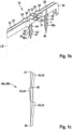
- Fig. 1a shows a perspective view of a possible embodiment of a horn device 10 according to the invention.
- the horn device 10 comprises a first contact element 20 and a second contact element 30.
- the contact elements 20 and 30 are essentially designed as contact sheet metal strips.
- the first contact element 20 forms the outer contact element, whereas the second contact element 30 forms the inner contact element. It can be seen that the contact elements 20 and 30 are spaced apart from one another.
- the first contact element 20 essentially has a U-shape.
- the base body 22 of the first contact element 20 accordingly comprises a connecting leg 25, a left side leg 26 and a right side leg 27.
- the second contact element 30 also essentially has a U-shape.
- the base body 32 of the second contact element 30 thus comprises a connecting leg 35, a left side leg 36 and a right side leg 37.
- first contact element 20 has anchoring pins 40a.
- the second contact element 30, on the other hand, has anchoring pins 40b.
- the first contact element 20 also has three contact lugs 21 .
- the second contact element 30 has three support lugs 31 .
- a detailed representation with regard to the complementary arrangement and positioning of the contact lugs 21 and support lugs 31 to one another is shown in Fig. 1b shown.
- Fig. 1a shows that the contact lugs 21, the support lugs 31 and the anchoring pins 40a and 40b are each arranged on the three legs 25, 35 and 26, 36 and 27, 37 in approximately the same area.
- the connecting leg 25 and 35 is an arrangement of the flags 21 and 31 and the Anchor pins 40a and 40b are provided in a central area.
- the arrangement of the lugs 21, 31 and the anchoring pins 40a, 40b is provided in an upper section, the upper section relating to the section of the left side legs 26, 36 pointing away from the connecting leg 25, 35.
- the lugs 21, 31 and the anchoring pins 40a and 40b are arranged in an upper section of the legs.
- the positioning of the contact lugs 21, 22 shown allows a reliable generation of a horn signal.
- the actuation of a horn cover on the steering wheel is reliably generated due to the three pairs of contact lugs positioned at a 9 o'clock position, 6 o'clock position and 3 o'clock position on the steering wheel.
- the first contact element 20 and the second contact element 30 remain in their positions due to the arrangement of the anchoring pins 40a and 40b in the area of the contact lugs 21, 31, so that the contact elements 20 and 30 cannot be unintentionally released here.
- Fig. 1b shows the formation of the contact lugs 21 and 31 to each other in an enlarged view.
- the contact lug 21 of the first contact element 20 protrudes essentially perpendicularly from the base body 22 .
- the base body 22 is designed as a contact plate and has a small material cross section.
- the contact lug 21 essentially has the shape of a platelet.
- a bent spring section 23 can also be seen.
- the contact lug 21 is formed over the support lug 31 .
- the curved spring section 23 of the contact lug 21 is formed over the support lug 31 in such a way that the curved spring section 23 can touch the support lug 31 when the contact lug 21 is actuated.
- the support lug 31 is also designed as a platelet-like element, with the support lug 31 being designed essentially perpendicular to the base body 32 of the second contact element 30 . Due to the choice of material, namely due to the use of a metal to form the first contact element 20 and the associated contact lug 21 and the formation of a bent spring section 23, the contact lug 21 can be used to actuate the horn device, i.e. to close the horn circuit, without great effort in the direction of the support lug 31 be moved. The deflection of the contact lug 21 is at decreasing external force influence reduced, so that the contact lug 21 can resume its resting state. The contact lug 21 has a restoring force so that it can be reset automatically into a position at a distance from the support lug 31 .
- Bending sections 28 of the first contact element 20 are also shown. These bending sections 28 are formed in the base body 22 .
- the second contact element 30 also has bending sections 38 in the base body 32 .
- the bending sections 28 and 38 are designed and positioned so as to complement one another in such a way that lead-through openings are formed between the contact elements 20 and 30 and have a substantially round cross section. These are used, for example, to fix cover elements or gas generators.
- an anchoring pin 40a, 40b In 1c the exact design of an anchoring pin 40a, 40b is shown.
- the anchoring pin 40a, 40b has, as is particularly evident from the perspective view in Fig. 1b can be seen, an elongated central portion 41 on.
- Latching elements 42 are formed to the side of the central section 41 .
- the longitudinal axis L of the anchoring pin 40a, 40b runs through the central section 41.
- a longitudinal plane is spanned by the longitudinal axis L together with a perpendicular to the longitudinal axis, which intersects the two side surfaces 48 . It can be seen that the latching elements 42 each run at an angle to this longitudinal plane LE.
- the first latching elements 43 which are arranged closest to the tip 46 of the anchoring pin 40a, 40b, are each designed to run obliquely with the same deviation from the longitudinal plane LE.
- the second latching elements 44 are in turn arranged in the opposite direction to the first latching elements 43 at an angle to the longitudinal plane LE.
- the third latching elements 45 run parallel and thus in the same direction of deviation from the first latching elements 43.
- the anchoring pins 40a and 40b have a barb-like structure.
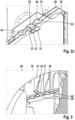
- FIG 2a the foam body 60 of a steering wheel 50 is shown. It can be seen that the foam body 60 has recesses 61 and 62 .
- the recess 61 serves to later accommodate the first contact element 20.
- the recess 62 serves to accommodate the second contact element 30.
- In the Recesses 61 and 62 are slit-shaped material recesses.
- Holes 64 can also be seen.
- the bending sections 28 and 38 of the contact elements 20 and 30 are positioned in the holes 64 .
- a free space 63 is also shown.
- the support lug 31 of a second contact element 30 is positioned in this free space 63 .
- the height H of the free space 63 is designed in such a way that a contact lug 21, preferably partially positioned in the free space 63, can be moved in the direction of the support lug 31 (see Figure 2c ).
- the foam body 60 is shown with a horn assembly 10 positioned therein. It can be seen that the lugs 21, 31 are formed in the 9 o'clock position and in the 3 o'clock position of the steering wheel 60. The 6 o'clock position cannot be seen in the example shown.
- FIG 2c the positioning of the horn device 10 is shown enlarged in a detailed representation.
- the contact lug 21 is arranged in relation to the second contact element 30, in particular to the support lug 31, that the bent spring section 23 points in the direction of the support lug 31 and is positioned in the free space 63.
- the contact lug 21 protrudes laterally beyond the foam body 60 . This facilitates the actuation of the contact lug 21, as shown in 3 is shown.
- a gas bag module 55 is shown.
- This gas bag module 55 is in the opening 15 (see Figure 2b ) brought in.
- the outer housing 56 to recognize.
- a projection 57 is formed on the outer housing 56 .
- This projection 57 is used to actuate the contact lug 21 of the first contact element 20 . If the airbag module 55 is pressed down when the horn cover is actuated, the projection 57 is pressed onto the contact lug 21 . This contact lug 21 then comes into contact with the support lug 31. The horn circuit is closed by this contact.
Landscapes
- Engineering & Computer Science (AREA)
- Mechanical Engineering (AREA)
- Physics & Mathematics (AREA)
- Acoustics & Sound (AREA)
- Chemical & Material Sciences (AREA)
- Combustion & Propulsion (AREA)
- Transportation (AREA)
- Air Bags (AREA)
- Steering Controls (AREA)
Description
- Die Erfindung betrifft ein Lenkrad gemäß dem Oberbegriff des Anspruchs 1 mit einer Hupeinrichtung sowie ein geeignetes Verfahren zur Herstellung eines solchen Lenkrads.
- Eine Hupeinrichtung für ein Lenkrad ist beispielsweise aus
EP 0 975 058 B1 bekannt. Diese Hupeinrichtung umfasst ein erstes sowie ein zweites Kontaktelement, wobei die Kontaktelemente als Drähte ausgebildet sind. Diese Drähte sind in einem Käfig gehalten, der Bereiche umfasst, in denen die Kontaktelemente in einem definierten Abstand zueinander gehalten werden. Weiterhin weist der Käfig Bereiche auf, in denen das erste Kontaktelement zumindest abstandsweise elastisch auslenkbar ist und im ausgelenkten Zustand das zweite Kontaktelement berührt. Auf diese Weise kann ein Hupstromkreis geschlossen werden. - Bekannte Hupeinrichtungen, die in einem separaten Käfig gelagert werden, müssen bei der Herstellung des Lenkrads aufwändig montiert werden. Die verschiedenen Bauteile der Hupeinrichtung müssen an das Lenkrad, insbesondere an das Lenkradskelett, oder an ein Gassackmodul montiert werden. Übliche Verbindungsmethoden sind dabei Schweißen, Nieten oder Verschrauben. Derartige Befestigungsmethoden weisen jedoch zum einen den Nachteil auf, dass es sich dabei um relativ langwierige Produktionsschritte handelt. Außerdem werden die Stücklistenkosten aufgrund der Verwendung von Käfigen, Schrauben, Niete etc. erhöht.
- Weitere Montagemethoden, wie z. B. das Verwenden von Befestigungsclips können jedoch nicht angewandt werden, da diese Befestigungsmethoden nicht dazu geeignet sind, Toleranzen bei der Fertigung eines Lenkrades zu überbrücken.
- Ein weiterer Nachteil bislang bekannter Hupeinrichtungen besteht darin, dass diese oftmals nicht für die neue Generation von Lenkrädern geeignet sind. Aufgrund von immer geringeren Abmessungen der Zentralbereiche neuerer Lenkradskelette nimmt der zur Verfügung stehende Platz hinsichtlich der Montagemöglichkeit einer Hupeinrichtung ab.
- Die
WO 2017/214214 A2 offenbart ein Fahrergassackmodul, in dessen Modulgehäuse eine Hupeinrichtung integriert ist, wobei die Hupeinrichtung zwei leitfähige Drähte umfasst. Die beiden Drähte sind im Ausgangszustand voneinander beabstandet, können jedoch bei Beaufschlagung einer Modulkappe miteinander in Kontakt kommen, um ein Hupsignal auszulösen. - Die
DE 20 2004 000 953 U1 offenbart ein Fahrzeuglenkrad, wobei ein Hupkontaktschalter des Lenkrads zwei elektrische Kontaktdrähte aufweist, welche mittels einer Relativbewegung von zwei Bauteilen in Berührung gebracht werden können, um eine Fahrzeughupe zu betätigen. Gemäß einer Ausführungsvariante sind die Kontaktdrähte dabei abschnittsweise in einen Schaumkörper des Lenkrads eingeschäumt. -
US2006016613 A1 offenbart ein Lenkrad mit einem ringförmigen Haltegriff, einem Innenteil der innerhalb des Haltegriffes einen mittleren Bereich des Lenkrades, welcher zur Aufnahme eines Gassackmoduls ausgebildet ist, ringförmig umgibt, sowie einer Hupeinrichtung für das Lenkrad, umfassend ein erstes Kontaktelement und ein zweites Kontaktelement, die voneinander beabstandet angeordnet sind, wobei die Hupeinrichtung in dem Innenteil fixiert ist. Die Kontaktelemente sind jeweils als Kontaktblech ausgebildet und durch einen Rahmen mit dem Lenkrad verbunden. Das erste Kontaktelement weist eine Kontaktfahne auf und das zweite Kontaktelement weist eine Auflagefahne auf, wobei die Kontaktfahne und die Auflagefahne derart komplementär zueinander ausgebildet und positioniert sind, dass die Kontaktfahne zum Schließen eines Hupstromkreises die Auflagefahne berührt. - Die Aufgabe der vorliegenden Erfindung ist es, ein weiterentwickeltes Lenkrad sowie ein Verfahren zur Herstellung eines solchen Lenkrads anzugeben. Insbesondere soll der für die Hupeinrichtung notwendige Platzbedarf im Zusammenhang mit dem zur Verfügung gestellten Lenkrad minimiert werden. Des Weiteren soll die Hupeinrichtung mit möglichst wenig, insbesondere keinen, zusätzlichen Bauteilen montierbar sein.
- Erfindungsgemäß wird diese Aufgabe im Hinblick auf das Lenkrad durch den Gegenstand des Patentanspruches 1 und im Hinblick auf das Verfahren zur Herstellung eines solchen Lenkrads durch den Gegenstand des Patentanspruches 11 gelöst.
- Vorteilhafte und zweckmäßige Ausgestaltungen des erfindungsgemäßen Lenkrads sowie des erfindungsgemäßen Verfahrens zur Herstellung eines Lenkrads sind in den Unteransprüchen angegeben.
- Die Erfindung beruht auf dem Gedanken, eine Hupeinrichtung für ein Lenkrad mit einem ersten Kontaktelement und mindestens einem zweiten Kontaktelement anzugeben, wobei die beiden Kontaktelemente voneinander beabstandet angeordnet sind.
- Insbesondere sind die Kontaktelemente käfigfrei in einem Schaumkörper des Lenkrades fixierbar.
- Indem die Kontaktelemente käfigfrei in einem Schaumkörper des Lenkrades fixierbar sind, bedarf es für die beiden Kontaktelemente kein zusätzliches Element, mittels dessen die Kontaktelemente zueinander positioniert werden müssten, oder das zu ihrer Befestigung am Schaumkörper erforderlich wäre. Hierdurch wird Montagezeit und -aufwand eingespart.
- Gemäß einer bevorzugten Ausführungsform der Erfindung ist vorgesehen, dass die Kontaktelemente jeweils einzeln und ohne Kontakt zu dem/den übrigen Kontaktelement(en), im Schaumkörper des Lenkrades verankert bzw. verankerbar sind.
- Erfindungsgemäß weist das erste Kontaktelement mindestens eine Kontaktfahne und das zweite Kontaktelement mindestens eine Auflagefahne auf. Die Kontaktfahne und die Auflagefahne sind derart komplementär zueinander ausgebildet und positioniert, dass die Kontaktfahne zum Schließen eines Hupstromkreises die Auflagefahne berührt.
- Bei Schließen eines Hupstromkreises erfolgt das Auslösen eines Hupsignals. Der Hupstromkreis kann einen Tonerzeuger umfassen, der ein Tonsignal, insbesondere ein Hupsignal, an einen Lautsprecher oder eine andere Signaltonabgabeeinrichtung überträgt.
- Auch aufgrund dieser Ausbildung der Hupeinrichtung, nämlich durch Ausbilden mindestens einer Kontaktfahne und einer zu dieser Kontaktfahne zugehörigen Auflagefahne, kann zum einen auf die Verwendung eines Befestigungskäfigs verzichtet werden. Zum anderen ist die Hupeinrichtung derart robust ausgebildet, als dass der Hupstromkreis zuverlässig geschlossen werden kann.
- Erfindungsgemäß sind die beiden Kontaktelemente als Kontaktbleche und nicht als Kontaktdrähte ausgebildet. Als Kontaktdraht ist ein derartiges Kontaktelement zu verstehen, das eine drahtförmige Form aufweist. Insbesondere weist ein derartiges Kontaktelement im Wesentlichen einen runden Querschnitt auf. Als Kontaktblech ist hingegen ein derartiges Kontaktelement zu verstehen, das aus einem Bandblech gebildet ist. Der Querschnitt eines derartigen Bandblechs ist relativ gering und insbesondere rechteckig ausgebildet.
- Das erste Kontaktelement und das zweite Kontaktelement weist jeweils mindestens einen Verankerungsstift auf. Vorzugsweise weisen das erste Kontaktelement und das zweite Kontaktelement jeweils mehrere Verankerungsstifte auf. In einer besonders bevorzugten Ausführungsform der Erfindung weist das erste Kontaktelement drei Verankerungsstifte auf, wobei das zweite Kontaktelement ebenfalls drei Verankerungsstifte aufweist.
- Der mindestens eine Verankerungsstift des ersten und/oder des zweiten Kontaktelements kann eine widerhakenartige Spitze aufweisen und/oder eine harpunenartige Form aufweisen. Im Allgemeinen kann der Verankerungsstift des ersten Kontaktelements und/oder des zweiten Kontaktelements widerhakenähnlich strukturiert sein. Auf diese Weise wird eine besonders gute Fixierung des ersten Kontaktelements und/oder des zweiten Kontaktelements in einem Schaumkörper des Lenkrads erreicht.
- Insbesondere ist mindestens ein Verankerungsstift derart ausgebildet, dass dieser einen länglichen Zentralabschnitt aufweist, wobei mehrere Verrastungselemente seitlich am länglichen Zentralabschnitt ausgebildet sind. Die Verrastungselemente stehen mit anderen Worten seitlich vom länglichen Zentralabschnitt ab. Vorzugsweise sind die Verrastungselemente, die insbesondere als Verrastungshaken ausgebildet sind, schräg zu einer Längsebene des länglichen Zentralabschnitts ausgebildet. Die Längsebene wird in Längsrichtung des länglichen Zentralabschnittes und von der seitlichen Senkrechte hierzu aufgespannt.
- Die Verrastungselemente sind entweder paarweise schräg zur Längsebene ausgebildet oder jeweils versetzt zueinander. Es ist möglich, dass zwei Verrastungselemente auf gleicher Höhe des länglichen Zentralabschnittes ausgebildet sind. Diese Verrastungselemente bilden ein Verrastungselement-Paar. Dieses Verrastungselement-Paar kann in gleicher schräg verlaufender Richtung zur Längsebene ausgebildet sein oder in entgegengesetzter Richtung. Eine derartige Struktur, die insbesondere als widerhakenähnliche Struktur bezeichnet werden kann, ermöglicht eine besonders gute Fixierung des Verankerungsstiftes in einem Schaumkörper.
- Der mindestens eine Verankerungsstift des ersten Kontaktelements und der mindestens eine Verankerungsstift des zweiten Kontaktelements sind vorzugsweise in einem gleichen Abschnitt ausgebildet.
- Die mindestens eine Kontaktfahne weist vorzugsweise einen gebogenen Federabschnitt auf. Der gebogene Federabschnitt ist vorzugsweise derart ausgebildet, dass eine Biegung in Richtung der komplementär zur Kontaktfahne ausgebildeten Auflagefahne ausgebildet ist. Ein derartig gebogener Federabschnitt erleichtert die Kontaktierung der Kontaktfahne mit der Auflagefahne. Sofern das erste Kontaktelement, nämlich die Kontaktfahne, betätigt wird, wird der gebogene Federabschnitt in Richtung der Auflagefahne bewegt.
- Aufgrund des gebogenen Federabschnitts kann der Abstand zwischen der Kontaktfahne und der Auflagefahne im betätigten Zustand der Hupeinrichtung überwunden werden, so dass ein elektrischer Kontakt zwischen der Kontaktfahne und der Auflagefahne hergestellt wird.
- Aufgrund der Ausbildung des gebogenen Federabschnitts kann die Kontaktfahne nach der Betätigung der Hupeinrichtung, d.h. nach Erzeugen des Hupsignals, selbsttätig in ihre Ausgangslage zurückversetzt werden.
- Die Kontaktfahne weist insbesondere eine derartige Rückstellkraft auf, dass sich die Kontaktfahne selbsttätig in eine von der Auflagefahne beabstandete Position zurückstellt. Die Verformung bzw. Auslenkung der Kontaktfahne wird bei nachlassendem äußeren Krafteinfluss reduziert, so dass die Kontaktfahne wieder ihren ursprünglichen Ruhezustand einnimmt.
- Dies erleichtert die Betätigung der Hupeinrichtung, da lediglich zur Herstellung einer elektrischen Verbindung zwischen der Kontaktfahne und der Auflagefahne und somit zum Erzeugen eines Hupsignals eine aktive Betätigung erfolgen muss. Das Hupsignal endet, sobald die Betätigungskraft nachlässt und die Rückstellkraft wirksam wir, so dass sich die beiden Fahnen voneinander beabstanden. Die Rückstellkraft kann aufgrund spezieller Ausbildung des Materials und/oder der Geometrie der mindestens einen Kontaktfahne gebildet werden bzw. ist durch das Material und/oder die Form einstellbar.
- Als Kontaktfahne ist insbesondere ein derartiges Bauteil zu verstehen, das dem Grunde nach eine Plättchenform aufweist. Dieses Plättchen kann zusätzlich strukturiert und/oder gebogen sein. Vorzugsweise steht die Kontaktfahne winklig von einer Blech- bzw. Bandblechform oder von einer Drahtform ab. In einer bevorzugten Ausführungsform der Erfindung steht die Kontaktfahne im Wesentlichen senkrecht von einer Blechform oder Drahtform ab.
- Als Auflagefahne ist insbesondere ein derartiges Bauteil zu verstehen, das im Wesentlichen eine Plättchenform aufweist. Dieses Plättchen kann zusätzlich strukturiert und/oder gebogen sein. Die Auflagefahne steht im Wesentlichen winklig von einer Blechform, insbesondere einer Bandblechform, oder einer Drahtform ab.
- In einer besonders bevorzugten Ausführungsform der Erfindung sind das erste Kontaktelement sowie das zweite Kontaktelement als Kontaktblechband ausgebildet, wobei die Kontaktfahne(n) und Auflagefahne(n) als von diesem Kontaktblechband abgewinkelte Plättchenformen ausgebildet sind. Vorzugsweise ist das erste Kontaktelement und/oder das zweite Kontaktelement einteilig ausgebildet. Die Kontaktfahne(n) und Auflagefahne(n) werden beim Herstellungsprozess von einem Grundkörper der Kontaktelemente abgebogen.
- In einer besonders bevorzugten Ausführungsform der Erfindung weisen das erste Kontaktelement und das zweite Kontaktelement im Wesentlichen jeweils eine U-Form auf. An allen drei Schenkel der U-Form ist vorzugsweise jeweils mindestens eine Kontaktfahne oder eine Auflagefahne ausgebildet. Mit anderen Worten weist das erste Kontaktelement im Wesentlichen eine U-Form auf, wobei an allen drei Schenkeln der U-Form jeweils mindestens eine Kontaktfahne ausgebildet ist. Das zweite Kontaktelement weist vorzugsweise ebenfalls eine U-Form auf, wobei an allen drei Schenkeln der U-Form jeweils mindestens eine Auflagefahne ausgebildet ist.
- Bei Ausbilden des ersten sowie des zweiten Kontaktelements mit einer im Wesentlichen U-Form, ist die Kontaktfahne sowie die Auflagefahne am Verbindungsschenkel der jeweiligen U-Form im Wesentlichen mittig positioniert bzw. ausgebildet. Vorzugsweise sind in diesem Bereich auch jeweils Verankerungsstifte, nämlich mindestens ein Verankerungsstift des ersten Kontaktelements und mindestens ein Verankerungsstift des zweiten Kontaktelements ausgebildet.
- An den beiden seitlichen Schenkeln der U-Form ist vorzugsweise in einem oberen Abschnitt, d.h. in einem vom Verbindungsschenkel wegweisenden Abschnitt des Schenkels die Kontaktfahne sowie die Auflagefahne ausgebildet. Vorzugsweise sind in diesem Bereich auch Verankerungsstifte ausgebildet, nämlich ein Verankerungsstift des ersten Kontaktelements sowie ein weiterer Verankerungsstift des zweiten Kontaktelements.
- Aufgrund der Ausbildung des ersten Kontaktelements sowie des zweiten Kontaktelements mit einer U-Form kann der in einem Lenkradskelett zur Verfügung gestellte Bauraum bestmöglich ausgenutzt werden. Vorzugsweise sind die Kontaktfahnen und die komplementär dazu ausgebildeten Auflagefahnen in derartigen Abschnitten des Lenkrads ausgebildet, die ein zuverlässiges Auslösen eines Hupsignals ermöglichen. Bei einer Draufsicht auf ein Lenkrad wird die Hupe mittig, unten bzw. seitlich betätigt. Eine Betätigung der Hupe in einem oberen Abschnitt des Lenkrads, insbesondere der Lenkrad-Abdeckung, wird von Autofahrern standardmäßig nicht vorgenommen, so dass in diesem Bereich keine Kontaktfahne bzw. Auflagefahne ausgebildet sein muss.
- Erfindungsgemäß weist das Lenkrad also einen, insbesondere ringförmigen, Haltegriff und einen Schaumkörper auf, der innerhalb des Haltegriffes einen mittleren Bereich des Lenkrades, welcher zur Aufnahme eines Gassackmoduls ausgebildet ist, ring- oder ringsegmentförmig umgibt.
- In diesem Schaumkörper ist die zuvor näher beschriebene Hupeinrichtung fixiert.
- Gemäß einer bevorzugten Ausführungsform weist der Schaumkörper zumindest zwei ring- oder ringsegmentförmige Ausnehmungen auf, in den das oder die Kontaktelemente fixiert ist bzw. fixierbar sind, wobei, vorzugsweise, zwei zueinander parallel verlaufende Ausnehmungen in dem Schaumkörper ausgebildet sind.
- Der Schaumkörper weist, gemäß einer weiter bevorzugten Ausführung zumindest eine weitere, insbesondere zwei weitere Ausnehmungen in einem Bereich auf, in der das oder die Kontaktelemente einer Kontaktfahne bzw. einer Auflagefahne aufweisen, wobei die weitere(n) Ausnehmung(en) zur Aufnahme und Positionierung der zumindest einen Positioniereinrichtung vorgesehen und ausgebildet sind, und wobei, weiter vorzugsweise, die weitere(n) Ausnehmung(en) als kreissegmentförmige Verbreiterung der Ausnehmung ausgebildet ist bzw. sind. Die Anordnung der Hupeinrichtung direkt im Schaumkörper des Lenkrads ist besonders platzsparend. Dadurch wird ermöglicht, Gassackmodule einzusetzen, die ein relativ großes Innenraumvolumen aufweisen. Außerdem ist der Wartungsaufwand bei einem erfindungsgemäßen Lenkrad reduziert, da bei einem Defekt der Hupeinrichtung das Gassackmodul nicht demontiert werden muss.
- Aufgrund der erfindungsgemäßen Ausbildung des Lenkrads wird der bereits zur Verfügung gestellte Bauraum effektiv ausgenutzt.
- Außerdem ist auf Grundlage der erfindungsgemäßen Ausbildung des Lenkrads keine komplexe Verbindungsgeometrie im Lenkrad bezüglich des Gassackmoduls notwendig.
- Vorzugsweise sind (die) Verankerungsstifte der Hupeinrichtung fest in dem Schaumkörper des Lenkrads eingebettet. Die Verankerungsstifte können derart ausgestaltet sein, dass eine sichere Fixierung der Hupeinrichtung im Schaumkörper erreicht wird.
- Zur Verbiegung der Kontaktfahne ist vorzugsweise eine Betätigungseinrichtung ausgebildet, die wenigstens einen in Richtung der Auflagefahne vorstehenden Vorsprung aufweist. Bei der Verbiegung der Kontaktfahne kann es sich auch um eine Änderung der Position der Kontaktfahne handeln. Der Vorsprung der Betätigungseinrichtung ist vorzugsweise derart positioniert, dass die Kontaktfahne des ersten Kontaktelements derart verformt oder verbogen oder bewegt wird, dass die Kontaktfahne die Auflagefahne zum Schließen eines Hupstromkreises berührt.
- In einer Ausführungsform der Erfindung kann ein Gassackmodul als Betätigungseinrichtung ausgebildet sein, wobei an dem Gassackmodul der beschriebene Vorsprung ausgebildet ist. Vorzugsweise ist der Vorsprung an einem Außengehäuseabschnitt des Gassackmoduls ausgebildet. Sofern die Betätigungseinrichtung als Teil des Gassackmoduls ausgebildet ist, trägt dies weiter zu einer verbesserten Raumausnutzung am Lenkrad bei, da keine separaten Bauteile notwendig sind, um eine Betätigungseinrichtung auszubilden.
- Gemäß der Erfindung weist der Schaumkörper des Lenkrads Ausnehmungen auf, wobei das erste Kontaktelement sowie das zweite Kontaktelement in den Ausnehmungen positioniert sind. Bei den Ausnehmungen handelt es sich erfindungsgemäß um schlitzförmige Ausnehmungen.
- Die Ausnehmungen weisen insbesondere eine derartige Tiefe auf, dass die als Kontaktbleche ausgebildeten Kontaktelemente mindestens überwiegend, vorzugsweise vollständig, in den Ausnehmungen positioniert sind.
- Die Ausnehmungen können als Materialentfernungen ausgebildet sein. Dies bedeutet, dass der Schaumkörper zunächst monolithisch ausgebildet ist und anschließend die Ausnehmungen durch Materialabtragungsvorgänge vom Schaumkörper entfernt werden. Des Weiteren ist es möglich, dass der Schaumkörper bereits mit den Materialausnehmungen, die auch als Aussparungen bezeichnet werden können, hergestellt wird. Diesbezüglich ist eine spezielle Werkzeugform zur Herstellung des Schaumkörpers notwendig.
- Vorzugsweise weist der Schaumkörper zwei voneinander beabstandet angeordnete Ausnehmungen auf, wobei in eine erste Ausnehmung das erste Kontaktelement positioniert wird und in eine zweite Ausnehmung das zweite Kontaktelement. Das zwischen den Ausnehmungen befindliche Material des Schaumkörpers dient als elektrisch isolierender Trennsteg. Mit anderen Worten sind die mindestens zwei Aussparungen durch einen Trennsteg voneinander getrennt. Der Trennsteg ist vorzugsweise aus dem Material des Schaumkörpers gebildet.
- Vorzugsweise weist in einem Abschnitt des Schaumkörpers, in dem eine Auflagefahne positioniert ist, einen Freiraum auf, derart, dass die Kontaktfahne in einem unbetätigten Zustand der Hupeinrichtung von der Auflagefahne beabstandet positioniert ist. Die Auflagefahne kann im Freiraum positioniert sein, wobei die Auflagefahne auf einem Abschnitt des Schaumkörpers aufliegt. Zwischen der Kontaktfahne und der Auflagefahne ist demnach kein Schaummaterial ausgebildet.
- Der Schaumkörper des Lenkrads ist vorzugsweise derart ausgebildet, dass zusätzlich in dem Abschnitt des Schaumkörpers, in dem die Kontaktfahne positioniert ist, ein/der Freiraum ausgebildet ist. Vorzugsweise ist der Freiraum des Schaumkörpers derart dimensioniert und ausgebildet, dass in dem Freiraum sowohl die Auflagefahne als auch die Kontaktfahne positioniert ist, wobei der benötigte Bewegungsumfang der Kontaktfahne zur Kontaktierung der Auflagefahne die Höhe des Freiraums definiert.
- Schließlich beruht die Erfindung auf dem Gedanken, ein Verfahren zur Herstellung eines zuvor beschriebenen Lenkrads anzugeben, wobei das Verfahren die folgenden Schritte umfasst:
- a) Bereitstellen eines Lenkradskeletts;
- b) Umschäumen des Lenkradskeletts zur Bildung des Schaumkörpers sowie gleichzeitiges oder nachträgliches Einbringen von Ausnehmungen in den Schaumkörper, wobei die Ausnehmungen als schlitzförmige Materialaussparungen ausgebildet sind;
- c) Bereitstellen der Hupeinrichtung;
- d) Positionieren der Hupeinrichtung in den Ausnehmungen.
- Aufgrund der erfindungsgemäßen Ausbildung des Lenkrads werden im Bereich des Lenkrads zur Herstellung einer Hupeinrichtung keine Kabelbäume notwendig.
- Die Schritte a) und c) können sowohl in umgekehrter Reihenfolge als auch gleichzeitig durchgeführt werden. Das heißt, dass es nicht erfindungswesentlich ist, ob zunächst das Lenkradskelett oder die Hupeinrichtung bereitgestellt wird.
- Beim Einbringen von Ausnehmungen in den Schaumkörper, können die Ausnehmungen mittels Schneid- und/oder Stanzvorgängen in den Schaumkörper eingebracht werden. Insbesondere ist es möglich, mittels eines Laserschneidverfahrens derartige Ausnehmungen präzise in den Schaumkörper einzubringen.
- Des Weiteren ist es möglich, dass die Ausnehmungen bereits beim Schäumungsvorgang in den Schaumkörper eingebracht werden. In diesem Fall weist bereits die Werkzeugform zur Durchführung des Umschäumungsvorganges die Ausnehmungen auf.
- Im Schritt d) werden insbesondere (die) Verankerungsstifte der Hupeinrichtung in den Schaumkörper eingedrückt.
- Das erfindungsgemäße Verfahren zur Herstellung eines Lenkrades ist insbesondere im Zusammenhang mit der Befestigung der Hupeinrichtung ohne weitere Hilfsmittel und Werkzeuge durchführbar. Somit kann der Produktionsablauf beschleunigt werden, was wirtschaftliche Vorteile hat. Außerdem wird die Herstellung des Lenkrades insofern vereinfacht, als dass aufgrund der im Schaumkörper ausgebildeten Ausnehmungen bereits die Positioniervorgaben hinsichtlich der einzubringenden Hupeinrichtung vorliegen. Es entfällt somit eine aufwändige Ausrichtung der Hupeinrichtung, insbesondere der Kontaktelemente.
- Die Erfindung wird im Folgenden anhand eines Ausführungsbeispiels unter Bezugnahme auf die beigefügten, schematischen Zeichnungen näher erläutert. Darin zeigen:
-
Fig. 1a eine perspektivische Ansicht einer Hupeinrichtung eines erfindungsgemäßen Lenkrads nach einem bevorzugten Ausführungsbeispiel; -
Fig. 1b eine vergrößerte Darstellung hinsichtlich der Positionierung einer Kontaktfahne sowie einer Auflagefahne zueinander; -
Fig. 1c eine vergrößerte Darstellung eines Verankerungsstifts; -
Fig. 2a eine Darstellung hinsichtlich der in einen Schaumkörper eingebrachten Ausnehmungen; -
Fig. 2b eine Darstellung hinsichtlich einer in ein erfindungsgemäßes Lenkrad eingebrachten Hupeinrichtung; -
Fig. 2c eine vergrößerte Darstellung einer Kontaktfahne sowie einer Auflagefahne im eingebauten Zustand; und -
Fig. 3 eine Darstellung hinsichtlich der Betätigung einer Kontaktfahne. - Im Folgenden werden für gleiche und gleichwirkende Teile dieselben Bezugsziffern verwendet.
-
Fig. 1a zeigt in einer perspektivischen Darstellung eine mögliche Ausführungsform hinsichtlich einer erfindungsgemäßen Hupeinrichtung 10. Die Hupeinrichtung 10 umfasst ein erstes Kontaktelement 20 sowie ein zweites Kontaktelement 30. Die Kontaktelemente 20 und 30 sind im Wesentlichen als Kontaktblechbänder ausgebildet. - Das erste Kontaktelement 20 bildet das äußere Kontaktelement, wohingegen das zweite Kontaktelement 30 das innere Kontaktelement bildet. Es ist zu erkennen, dass die Kontaktelemente 20 und 30 voneinander beabstandet ausgebildet sind.
- Das erste Kontaktelement 20 weist im Wesentlichen eine U-Form auf. Der Grundkörper 22 des ersten Kontaktelements 20 umfasst demnach einen Verbindungsschenkel 25, einen linken Seitenschenkel 26 sowie einen rechten Seitenschenkel 27.
- Das zweite Kontaktelement 30 weist ebenfalls im Wesentlichen eine U-Form auf. Der Grundkörper 32 des zweiten Kontaktelements 30 umfasst somit einen Verbindungsschenkel 35 einen linken Seitenschenkel 36 sowie einen rechten Seitenschenkel 37.
- Des Weiteren ist zu erkennen, dass das erste Kontaktelement 20 Verankerungsstifte 40a aufweist. Das zweite Kontaktelement 30 weist hingegen Verankerungsstifte 40b auf. Das erste Kontaktelement 20 weist außerdem drei Kontaktfahnen 21 auf. Das zweite Kontaktelement 30 weist drei Auflagefahnen 31 auf. Eine detaillierte Darstellung hinsichtlich der komplementären Anordnung und Positionierung der Kontaktfahnen 21 und Auflagefahnen 31 zueinander ist in
Fig. 1b dargestellt. -
Fig. 1a zeigt, dass die Kontaktfahnen 21, die Auflagefahnen 31 sowie die Verankerungsstifte 40a und 40b an den jeweils drei Schenkeln 25, 35 sowie 26, 36 und 27, 37 jeweils in etwa im gleichen Bereich angeordnet sind. Im Bereich der Verbindungsschenkel 25 und 35 ist eine Anordnung der Fahnen 21 und 31 sowie der Verankerungsstifte 40a und 40b in einem mittigen Bereich vorgesehen. Im Bereich der linken Seitenschenkel 26, 36 ist die Anordnung der Fahnen 21, 31 sowie der Verankerungsstifte 40a, 40b in einem oberen Abschnitt vorgesehen, wobei der obere Abschnitt den Abschnitt der linken Seitenschenkel 26, 36 betrifft, die vom Verbindungsschenkel 25, 35 wegweisen. Gleiches trifft im Zusammenhang mit den rechten Seitenschenkeln 27, 37 zu. Auch hier ist eine Anordnung der Fahnen 21, 31 sowie der Verankerungsstifte 40a und 40b in einem oberen Abschnitt der Schenkel vorgesehen. - Die dargestellte Positionierung der Kontaktfahnen 21, 22 ermöglicht eine zuverlässige Erzeugung eines Hupsignals. Die Betätigung einer Hupenabdeckung am Lenkrad wird aufgrund der drei positionierten Kontaktfahnen-Paare an einer 9-Uhr-Position, 6-Uhr-Position sowie 3-Uhr-Position am Lenkrad zuverlässig erzeugt. Gleichzeitig verbleiben das erste Kontaktelement 20 sowie das zweite Kontaktelement 30 aufgrund der Anordnung der Verankerungsstifte 40a und 40b im Bereich der Kontaktfahnen 21, 31 in ihren Positionen, so dass hier kein unbeabsichtigtes Lösen der Kontaktelemente 20 und 30 erfolgt.
- In
Fig. 1b ist die Ausbildung der Kontaktfahnen 21 und 31 zueinander in einer vergrößerten Darstellung gezeigt. Die Kontaktfahne 21 des ersten Kontaktelements 20 steht dabei im Wesentlichen senkrecht von dem Grundkörper 22 ab. Der Grundkörper 22 ist als Kontaktblech ausgebildet und weist einen geringen Materialquerschnitt auf. Die Kontaktfahne 21 weist im Wesentlichen eine Plättchenform auf. Des Weiteren ist ein gebogener Federabschnitt 23 zu erkennen. Die Kontaktfahne 21 ist über der Auflagefahne 31 ausgebildet. Insbesondere ist der gebogene Federabschnitt 23 der Kontaktfahne 21 derart über der Auflagefahne 31 ausgebildet, dass bei Betätigung der Kontaktfahne 21 der gebogene Federabschnitt 23 die Auflagefahne 31 berühren kann. - Die Auflagefahne 31 ist ebenfalls als plättchenartiges Element ausgebildet, wobei die Auflagefahne 31 im Wesentlichen senkrecht zum Grundkörper 32 des zweiten Kontaktelements 30 ausgebildet ist. Aufgrund der Materialauswahl, nämlich aufgrund der Verwendung eines Metalls zur Ausbildung des ersten Kontaktelements 20 sowie der zugehörigen Kontaktfahne 21 sowie der Ausbildung eines gebogenen Federabschnitts 23 kann die Kontaktfahne 21 zur Betätigung der Hupeinrichtung, d.h. zum Schließen des Hupstromkreises ohne großen Kraftaufwand in Richtung der Auflagefahne 31 bewegt werden. Die Auslenkung der Kontaktfahne 21 wird bei nachlassendem äußeren Krafteinfluss reduziert, so dass die Kontaktfahne 21 wieder ihren Ruhezustand einnehmen kann. Die Kontaktfahne 21 weist eine Rückstellkraft auf, so dass diese selbsttätig in eine von der Auflagefahne 31 beabstandete Position zurückstellbar ist.
- Ebenfalls dargestellt sind Biegeabschnitte 28 des ersten Kontaktelements 20. Diese Biegeabschnitte 28 sind im Grundkörper 22 ausgebildet. Auch das zweite Kontaktelement 30 weist im Grundkörper 32 Biegeabschnitte 38 auf. Die Biegeabschnitte 28 und 38 sind derart komplementär zueinander ausgebildet und positioniert, dass zwischen den Kontaktelementen 20 und 30 Durchführungsöffnungen ausgebildet sind, die im Wesentlichen einen runden Querschnitt aufweisen. Diese dienen beispielsweise zur Fixierung von Abdeckungselementen bzw. Gasgeneratoren.
- In
Fig. 1c ist die genaue Ausführung eines Verankerungsstifts 40a, 40b dargestellt. Der Verankerungsstift 40a, 40b weist, wie dies insbesondere aufgrund der perspektivischen Ansicht inFig. 1b erkennbar ist, einen länglichen Zentralabschnitt 41 auf. Seitlich des Zentralabschnitts 41 sind Verrastungselemente 42 ausgebildet. Durch den Zentralabschnitt 41 verläuft die Längsachse L des Verankerungsstifts 40a, 40b. Von der Längsachse L wird zusammen mit einer Senkrechten zur Längsachse, die die beiden Seitenflächen 48 schneidet, eine Längsebene aufgespannt. Es ist zu erkennen, dass die Verrastungselemente 42 jeweils winklig zu dieser Längsebene LE verlaufen. - Die ersten Verrastungselemente 43, die am nächsten zur Spitze 46 des Verankerungsstiftes 40a, 40b angeordnet sind, sind jeweils in gleicher Abweichung zur Längsebene LE schrägverlaufend ausgebildet. Die zweiten Verrastungselemente 44 sind wiederum in die entgegengesetzte Richtung zu den ersten Verrastungselementen 43 schrägverlaufend zur Längsebene LE angeordnet. Die dritten Verrastungselemente 45 verlaufen hingegen parallel und somit in gleicher Abweichungsrichtung zu den ersten Verrastungselementen 43. Die Verankerungsstifte 40a und 40b weisen eine widerhakenartige Struktur auf.
- In
Fig. 2a ist der Schaumkörper 60 eines Lenkrads 50 dargestellt. Es ist zu erkennen, dass der Schaumkörper 60 Ausnehmungen 61 und 62 aufweist. Die Ausnehmung 61 dient zur späteren Aufnahme des ersten Kontaktelements 20. Die Ausnehmung 62 dient zur Aufnahme des zweiten Kontaktelements 30. Bei den Ausnehmungen 61 und 62 handelt es sich um schlitzförmige Materialaussparungen. - Des Weiteren sind Löcher 64 zu erkennen. In den Löchern 64 sind im montierten Zustand die Biegeabschnitte 28 und 38 der Kontaktelemente 20 und 30 positioniert. Ebenfalls ist ein Freiraum 63 dargestellt. In diesem Freiraum 63 ist im montierten Zustand die Auflagefahne 31 eines zweiten Kontaktelements 30 positioniert. Die Höhe H des Freiraums 63 ist derart ausgebildet, dass eine, vorzugsweise teilweise im Freiraum 63 positionierte, Kontaktfahne 21 in Richtung der Auflagefahne 31 bewegt werden kann (siehe hierzu
Fig. 2c ). - In
Fig. 2b ist der Schaumkörper 60 mit einer darin positionierten Hupeinrichtung 10 dargestellt. Es ist zu erkennen, dass die Fahnen 21, 31 in 9-Uhr-Position sowie in 3-Uhr-Position des Lenkrads 60 ausgebildet sind. Die 6-Uhr-Position ist im dargestellten Beispiel nicht zu erkennen. - In
Fig. 2c ist die Positionierung der Hupeinrichtung 10 in einer detaillierten Darstellung vergrößert gezeigt. Es ist zu erkennen, dass die Kontaktfahne 21 derart in Relation zum zweiten Kontaktelement 30, insbesondere zur Auflagefahne 31, angeordnet ist, dass der gebogene Federabschnitt 23 in Richtung der Auflagefahne 31 weist und im Freiraum 63 positioniert ist. Im dargestellten Beispiel steht die Kontaktfahne 21 seitlich über den Schaumkörper 60 über. Dies erleichtert die Betätigung der Kontaktfahne 21, wie dies inFig. 3 dargestellt ist. - In
Fig. 3 ist ein Gassackmodul 55 dargestellt. Dieses Gassackmodul 55 ist in die Öffnung 15 (sieheFig. 2b ) eingebracht. Insbesondere ist inFig. 3 das Außengehäuse 56 zu erkennen. An dem Außengehäuse 56 ist ein Vorsprung 57 ausgebildet. Dieser Vorsprung 57 dient zur Betätigung der Kontaktfahne 21 des ersten Kontaktelements 20. Sofern das Gassackmodul 55 bei einer Betätigung der Hupenabdeckung nach unten gedrückt wird, wird der Vorsprung 57 auf die Kontaktfahne 21 gedrückt. Diese Kontaktfahne 21 kommt dann in Kontakt mit der Auflagefahne 31. Der Hupstromkreis wird durch diese Berührung geschlossen. -
- 10
- Hupeinrichtung
- 15
- Öffnung
- 20
- erstes Kontaktelement
- 21
- Kontaktfahne
- 22
- Grundkörper
- 23
- gebogener Federabschnitt
- 25
- Verbindungsschenkel
- 26
- linker Seitenschenkel
- 27
- rechter Seitenschenkel
- 28
- Biegeabschnitt
- 30
- zweites Kontaktelement
- 31
- Auflagefahne
- 32
- Grundkörper
- 35
- Verbindungsschenkel
- 36
- linker Seitenschenkel
- 37
- rechter Seitenschenkel
- 38
- Biegeabschnitt
- 40a, 40b
- Verankerungsstift
- 41
- länglicher Zentralabschnitt
- 42
- Verrastungselement
- 43
- erstes Verrastungselement
- 44
- zweites Verrastungselement
- 45
- drittes Verrastungselement
- 46
- Spitze
- 48
- Seitenfläche
- 50
- Lenkrad
- 55
- Gassackmodul
- 56
- Außengehäuse
- 57
- Vorsprung
- 60
- Schaumkörper
- 61
- Ausnehmung erstes Kontaktelement
- 62
- Ausnehmung zweites Kontaktelement
- 63
- Freiraum
- 64
- Loch
- L
- Längsachse Verankerungsstift
- LE
- Längsebene
- H
- Höhe Freiraum
Claims (12)
- Lenkrad (50) miteinem, insbesondere ringförmigen, Haltegriff,einem Schaumkörper (60) der innerhalb des Haltegriffes einen mittleren Bereich des Lenkrades (50), welcher zur Aufnahme eines Gassackmoduls (55) ausgebildet ist, ring- oder ringsegmentförmig umgibt, sowieeiner Hupeinrichtung (10) für das Lenkrad (50), umfassend ein erstes Kontaktelement (20) und mindestens ein zweites Kontaktelement (30), die voneinander beabstandet angeordnet sind,wobei die Hupeinrichtung (10) in dem Schaumkörper (60) fixiert ist,wobei die Kontaktelemente (20, 30) jeweils als Kontaktblech ausgebildet sind und der Schaumkörper (60) als schlitzförmige Materialaussparungen ausgebildete Ausnehmungen (61, 62) zur späteren Aufnahme der Kontaktelemente (20, 30) aufweist,wobei das erste Kontaktelement (20) mindestens eine Kontaktfahne (21) aufweist und das zweite Kontaktelement (30) mindestens eine Auflagefahne (31) aufweist, wobei die Kontaktfahne (21) und die Auflagefahne (31) derart komplementär zueinander ausgebildet und positioniert sind, dass die Kontaktfahne (21) zum Schließen eines Hupstromkreises die Auflagefahne (31) berührt.
- Lenkrad nach Anspruch 1, dadurch gekennzeichnet, dass die Kontaktelemente (20, 30) jeweils einzeln und ohne Kontakt zu dem/den übrigen Kontaktelement(en) (30), im Schaumkörper des Lenkrades verankert bzw. verankerbar sind.
- Lenkrad nach Anspruch 1 oder 2, dadurch gekennzeichnet, dass das erste Kontaktelement (20) und/oder das zweite Kontaktelement (30) jeweils mindestens einen Verankerungsstift (40a, 40b) aufweisen, wobei dieser, vorzugsweise, eine widerhakenartige Spitze und/oder eine harpunenartige Form und/oder eine widerhakenartige bzw. tannenbaumartige Struktur aufweist.
- Lenkrad nach einem der vorangegangenen Ansprüche, dadurch gekennzeichnet, dass die Kontaktfahne (21) einen gebogenen Federabschnitt (23) aufweist und/oder, dass die Kontaktfahne (21) eine Rückstellkraft aufweist, derart, dass sich die Kontaktfahne (21) selbsttätig in eine von der Auflagefahne (31) beabstandete Position zurückstellt.
- Lenkrad nach einem der vorangegangenen Ansprüche, dadurch gekennzeichnet, dass das erste Kontaktelement (20) und vorzugsweise auch das zweite Kontaktelement (30) im Bereich seiner Kontaktfahne (21) bzw. seiner Auflagefahne (31) zumindest eine Positioniereinrichtung (28, 30) aufweist, insbesondere in Form einer, vorzugsweise kreisringsegmentförmigen, Formabweichung des Kontaktelementes (20, 30), mittels der das Kontaktelement gegenüber dem Schaumkörper (60) des Lenkrades (50), insbesondere entlang seiner Längserstreckung, positionierbar ist, wobei vorzugsweise beiderseits der Kontaktfahne (21) bzw. Auflagefahne (31) jeweils eine Positioniereinrichtung (28, 30) ausgebildet ist.
- Lenkrad nach einem der vorangegangenen Ansprüche, dadurch gekennzeichnet, dass das erste Kontaktelement (20) und das zweite Kontaktelement (30) jeweils im Wesentlichen eine U-Form aufweisen, wobei jeweils an allen drei Schenkeln (25, 26, 27, 35, 36, 37) der U-Form mindestens eine Kontaktfahne (21) oder eine Auflagefahne (31) ausgebildet ist.
- Lenkrad (50) nach einem der vorangegangenen Ansprüche, dadurch gekennzeichnet, dass der Schaumkörper (60) zumindest zwei ring- oder ringsegmentförmige Ausnehmungen (61, 62) aufweist, in den die Kontaktelemente (20, 30) fixiert bzw. fixierbar sind, wobei, vorzugsweise, die Ausnehmungen (61, 62) als zwei zueinander parallel verlaufende Ausnehmungen (61, 62) in dem Schaumkörper ausgebildet sind.
- Lenkrad (50) nach zumindest einem der vorangegangenen Ansprüche, dadurch gekennzeichnet, dass der Schaumkörper (60) zumindest eine weitere, insbesondere zwei weitere Ausnehmungen (64) in einem Bereich aufweist, in der das oder die Kontaktelemente (20, 30) einer Kontaktfahne (21) bzw. einer Auflagefahne (31) aufweisen, wobei die weitere(n) Ausnehmung(en) zur Aufnahme und Positionierung der zumindest einen Positioniereinrichtung (28, 30) vorgesehen und ausgebildet sind, und wobei, weiter vorzugsweise, die weitere(n) Ausnehmung(en) (64) als kreissegmentförmige Verbreiterung der Ausnehmung (61, 62) ausgebildet ist.
- Lenkrad (50) nach zumindest einem der vorangegangenen Ansprüche, dadurch gekennzeichnet, dass Verankerungsstifte (40a, 40b) der Hupeinrichtung (10) fest in dem Schaumkörper (60) eingebettet sind, und/oder dass zum Schließen eines Hupstromkreises, insbesondere zur Bewegung einer hierzu dienenden Kontaktfahne (21), eine Betätigungseinrichtung ausgebildet ist, die insbesondere wenigstens einen in Richtung der Auflagefahne (31) vorstehenden Vorsprung (56) aufweist, wobei vorzugsweise ein Gassackmodul (55) als Betätigungseinrichtung ausgebildet ist, an dem der Vorsprung (57) ausgebildet ist, der vorzugsweise an einem Außengehäuseabschnitt (56) des Gassackmoduls (55) ausgebildet ist.
- Lenkrad (50) nach zumindest einem der vorangegangenen Ansprüche, dadurch gekennzeichnet, dass die Ausnehmungen (61, 62) in einem Abschnitt des Schaumkörpers (60), in dem eine Auflagefahne (31) positioniert ist, einen Freiraum (63) bilden, derart, dass die Kontaktfahne (21) in einem unbetätigten Zustand der Hupeinrichtung (10) von der Auflagefahne (31) beabstandet positioniert ist.
- Verfahren zur Herstellung eines Lenkrads (50) nach einem der vorangegangenen Ansprüche, umfassend die folgenden Schritte:a) Bereitstellen eines Lenkradskeletts;b) Umschäumen des Lenkradskeletts zur Bildung des Schaumkörpers (60) sowie gleichzeitiges oder nachträgliches Einbringen von Ausnehmungen (61, 62, 64) in den Schaumkörper (60), wobei zwei Ausnehmungen (61, 62) als schlitzförmige Materialaussparungen ausgebildet sind;c) Bereitstellen der Hupeinrichtung (10);d) Positionieren der Hupeinrichtung (10) in den Ausnehmungen (61, 62).
- Verfahren nach Anspruch 11, dadurch gekennzeichnet, dass im Schritt d) Verankerungsstifte (40a, 40b) der Hupeinrichtung (10) in den Schaumkörper (60) eingedrückt werden.
Applications Claiming Priority (2)
| Application Number | Priority Date | Filing Date | Title |
|---|---|---|---|
| DE102018131324.1A DE102018131324A1 (de) | 2018-12-07 | 2018-12-07 | Hupeinrichtung für ein Lenkrad, Lenkrad mit einer derartigen Hupeinrichtung sowie Herstellungsverfahren |
| PCT/EP2019/083596 WO2020115094A1 (de) | 2018-12-07 | 2019-12-04 | Hupeinrichtung für ein lenkrad, lenkrad mit einer derartigen hupeinrichtung sowie herstellungsverfahren |
Publications (2)
| Publication Number | Publication Date |
|---|---|
| EP3891017A1 EP3891017A1 (de) | 2021-10-13 |
| EP3891017B1 true EP3891017B1 (de) | 2023-08-30 |
Family
ID=69005679
Family Applications (1)
| Application Number | Title | Priority Date | Filing Date |
|---|---|---|---|
| EP19827628.9A Active EP3891017B1 (de) | 2018-12-07 | 2019-12-04 | Hupeinrichtung für ein lenkrad, lenkrad mit einer derartigen hupeinrichtung sowie herstellungsverfahren |
Country Status (4)
| Country | Link |
|---|---|
| EP (1) | EP3891017B1 (de) |
| CN (1) | CN113165574A (de) |
| DE (1) | DE102018131324A1 (de) |
| WO (1) | WO2020115094A1 (de) |
Families Citing this family (1)
| Publication number | Priority date | Publication date | Assignee | Title |
|---|---|---|---|---|
| CN116061804B (zh) * | 2021-11-04 | 2026-04-28 | 延锋汽车智能安全系统有限责任公司 | 车辆方向盘 |
Citations (1)
| Publication number | Priority date | Publication date | Assignee | Title |
|---|---|---|---|---|
| DE20213908U1 (de) * | 2002-09-09 | 2003-01-30 | TRW Automotive Safety Systems GmbH & Co. KG, 63743 Aschaffenburg | Airbagmodul sowie Baugruppe aus einem Lenkrad und einem Airbagmodul |
Family Cites Families (7)
| Publication number | Priority date | Publication date | Assignee | Title |
|---|---|---|---|---|
| DE809765C (de) * | 1949-10-15 | 1951-08-02 | Petri Lenkradwerk | Signalvorrichtung fuer Kraftfahrzeuge |
| DE29813239U1 (de) | 1998-07-24 | 1998-10-01 | TRW Automotive Safety Systems GmbH, 63743 Aschaffenburg | Kontaktvorrichtung |
| DE202004000953U1 (de) * | 2004-01-22 | 2004-05-27 | Trw Automotive Safety Systems Gmbh | Fahrzeuglenkrad |
| US7126073B2 (en) * | 2004-07-21 | 2006-10-24 | Fci Usa, Inc. | Intermittent connection device |
| DE202014002484U1 (de) * | 2014-03-21 | 2015-06-29 | Dalphi Metal Espana, S.A. | Hupeneinrichtung für ein Lenkrad und Lenkrad mit einer Hupeneinrichtung |
| WO2017214214A2 (en) * | 2016-06-10 | 2017-12-14 | Key Safety Systems, Inc. | Air bag module |
| DE202018103190U1 (de) * | 2018-06-07 | 2018-06-15 | Dalphi Metal Espana, S.A. | Hupenbaugruppe für ein Fahrzeuglenkrad |
-
2018
- 2018-12-07 DE DE102018131324.1A patent/DE102018131324A1/de not_active Withdrawn
-
2019
- 2019-12-04 WO PCT/EP2019/083596 patent/WO2020115094A1/de not_active Ceased
- 2019-12-04 CN CN201980081091.7A patent/CN113165574A/zh active Pending
- 2019-12-04 EP EP19827628.9A patent/EP3891017B1/de active Active
Patent Citations (1)
| Publication number | Priority date | Publication date | Assignee | Title |
|---|---|---|---|---|
| DE20213908U1 (de) * | 2002-09-09 | 2003-01-30 | TRW Automotive Safety Systems GmbH & Co. KG, 63743 Aschaffenburg | Airbagmodul sowie Baugruppe aus einem Lenkrad und einem Airbagmodul |
Also Published As
| Publication number | Publication date |
|---|---|
| WO2020115094A1 (de) | 2020-06-11 |
| CN113165574A (zh) | 2021-07-23 |
| DE102018131324A1 (de) | 2020-06-10 |
| EP3891017A1 (de) | 2021-10-13 |
Similar Documents
| Publication | Publication Date | Title |
|---|---|---|
| DE69607325T2 (de) | Schnappbefestigung für sonnenblende und elektrische verbinder für sonnenblendbefestigungen | |
| EP0945311B1 (de) | Aufprall-Schutzvorrichtung | |
| EP2165580B1 (de) | Schliesssystem für fahrzeuge und verwendung eines komponententrägers | |
| EP1197402A2 (de) | Fahrzeuglenkrad | |
| DE10304278B4 (de) | Struktur zur Befestigung einer Anzeigeeinheit an einer Instrumentenkonsole eines Automobils | |
| DE4413756C1 (de) | Gehäuse für einen Steckverbinder | |
| DE112017002762T5 (de) | Rahmenantenne | |
| EP3891017B1 (de) | Hupeinrichtung für ein lenkrad, lenkrad mit einer derartigen hupeinrichtung sowie herstellungsverfahren | |
| DE102015003473A1 (de) | Hupeneinrichtung für ein lenkrad, lenkrad mit einer derartigen hupeneinrichtung sowie herstellungsverfahren | |
| DE4310369A1 (de) | Adapter | |
| DE102016200243A1 (de) | Kontaktverbinder, Anschlusskontakt und Verfahren zur Herstellung eines Kontaktverbinders | |
| EP2732508B1 (de) | Direktsteckelement mit integrierter verriegelung | |
| EP1912295A1 (de) | Stromschiene | |
| DE102004001899A1 (de) | Sperrkreisanordnung | |
| WO2018006894A1 (de) | Verfahren zur herstellung eines elektrokomponententrägers für automobile anwendungen | |
| EP3934944B1 (de) | Hupenbaugruppe, verfahren zu deren herstellung sowie fahrzeuglenkvorrichtung mit einer solchen hupenbaugruppe | |
| DE69821547T2 (de) | Verfahren zur Herstellung von elektrischen Verbindern und Verbinder | |
| EP0975058A2 (de) | Kontaktvorrichtung | |
| EP3576984B1 (de) | Hupenbetätigungseinheit | |
| DE102021117849B4 (de) | Verbindungseinheit und Verfahren | |
| WO2014202306A1 (de) | Schalter, verfahren zum herstellen eines schalters und elektronikmodulsystem | |
| DE102015111885A1 (de) | Sicherung für Stromverteiler | |
| EP0456984B1 (de) | Steckschalter | |
| DE19501855C2 (de) | Verfahren zur Herstellung einer mehrere funktional eigenständige elektrische Schalter aufweisenden Schalteranordnung | |
| EP0762549A2 (de) | Elektrischer Verbinder |
Legal Events
| Date | Code | Title | Description |
|---|---|---|---|
| STAA | Information on the status of an ep patent application or granted ep patent |
Free format text: STATUS: UNKNOWN |
|
| STAA | Information on the status of an ep patent application or granted ep patent |
Free format text: STATUS: THE INTERNATIONAL PUBLICATION HAS BEEN MADE |
|
| PUAI | Public reference made under article 153(3) epc to a published international application that has entered the european phase |
Free format text: ORIGINAL CODE: 0009012 |
|
| STAA | Information on the status of an ep patent application or granted ep patent |
Free format text: STATUS: REQUEST FOR EXAMINATION WAS MADE |
|
| 17P | Request for examination filed |
Effective date: 20210707 |
|
| AK | Designated contracting states |
Kind code of ref document: A1 Designated state(s): AL AT BE BG CH CY CZ DE DK EE ES FI FR GB GR HR HU IE IS IT LI LT LU LV MC MK MT NL NO PL PT RO RS SE SI SK SM TR |
|
| DAV | Request for validation of the european patent (deleted) | ||
| DAX | Request for extension of the european patent (deleted) | ||
| GRAP | Despatch of communication of intention to grant a patent |
Free format text: ORIGINAL CODE: EPIDOSNIGR1 |
|
| STAA | Information on the status of an ep patent application or granted ep patent |
Free format text: STATUS: GRANT OF PATENT IS INTENDED |
|
| RIC1 | Information provided on ipc code assigned before grant |
Ipc: B62D 1/04 20060101ALI20230323BHEP Ipc: B60R 21/203 20060101ALI20230323BHEP Ipc: B60Q 5/00 20060101AFI20230323BHEP |
|
| INTG | Intention to grant announced |
Effective date: 20230420 |
|
| GRAS | Grant fee paid |
Free format text: ORIGINAL CODE: EPIDOSNIGR3 |
|
| GRAA | (expected) grant |
Free format text: ORIGINAL CODE: 0009210 |
|
| STAA | Information on the status of an ep patent application or granted ep patent |
Free format text: STATUS: THE PATENT HAS BEEN GRANTED |
|
| AK | Designated contracting states |
Kind code of ref document: B1 Designated state(s): AL AT BE BG CH CY CZ DE DK EE ES FI FR GB GR HR HU IE IS IT LI LT LU LV MC MK MT NL NO PL PT RO RS SE SI SK SM TR |
|
| REG | Reference to a national code |
Ref country code: GB Ref legal event code: FG4D Free format text: NOT ENGLISH |
|
| REG | Reference to a national code |
Ref country code: CH Ref legal event code: EP |
|
| REG | Reference to a national code |
Ref country code: DE Ref legal event code: R096 Ref document number: 502019009197 Country of ref document: DE |
|
| REG | Reference to a national code |
Ref country code: IE Ref legal event code: FG4D Free format text: LANGUAGE OF EP DOCUMENT: GERMAN |
|
| REG | Reference to a national code |
Ref country code: LT Ref legal event code: MG9D |
|
| REG | Reference to a national code |
Ref country code: NL Ref legal event code: MP Effective date: 20230830 |
|
| PG25 | Lapsed in a contracting state [announced via postgrant information from national office to epo] |
Ref country code: GR Free format text: LAPSE BECAUSE OF FAILURE TO SUBMIT A TRANSLATION OF THE DESCRIPTION OR TO PAY THE FEE WITHIN THE PRESCRIBED TIME-LIMIT Effective date: 20231201 |
|
| PG25 | Lapsed in a contracting state [announced via postgrant information from national office to epo] |
Ref country code: IS Free format text: LAPSE BECAUSE OF FAILURE TO SUBMIT A TRANSLATION OF THE DESCRIPTION OR TO PAY THE FEE WITHIN THE PRESCRIBED TIME-LIMIT Effective date: 20231230 |
|
| PG25 | Lapsed in a contracting state [announced via postgrant information from national office to epo] |
Ref country code: SE Free format text: LAPSE BECAUSE OF FAILURE TO SUBMIT A TRANSLATION OF THE DESCRIPTION OR TO PAY THE FEE WITHIN THE PRESCRIBED TIME-LIMIT Effective date: 20230830 Ref country code: RS Free format text: LAPSE BECAUSE OF FAILURE TO SUBMIT A TRANSLATION OF THE DESCRIPTION OR TO PAY THE FEE WITHIN THE PRESCRIBED TIME-LIMIT Effective date: 20230830 Ref country code: NO Free format text: LAPSE BECAUSE OF FAILURE TO SUBMIT A TRANSLATION OF THE DESCRIPTION OR TO PAY THE FEE WITHIN THE PRESCRIBED TIME-LIMIT Effective date: 20231130 Ref country code: LV Free format text: LAPSE BECAUSE OF FAILURE TO SUBMIT A TRANSLATION OF THE DESCRIPTION OR TO PAY THE FEE WITHIN THE PRESCRIBED TIME-LIMIT Effective date: 20230830 Ref country code: LT Free format text: LAPSE BECAUSE OF FAILURE TO SUBMIT A TRANSLATION OF THE DESCRIPTION OR TO PAY THE FEE WITHIN THE PRESCRIBED TIME-LIMIT Effective date: 20230830 Ref country code: IS Free format text: LAPSE BECAUSE OF FAILURE TO SUBMIT A TRANSLATION OF THE DESCRIPTION OR TO PAY THE FEE WITHIN THE PRESCRIBED TIME-LIMIT Effective date: 20231230 Ref country code: HR Free format text: LAPSE BECAUSE OF FAILURE TO SUBMIT A TRANSLATION OF THE DESCRIPTION OR TO PAY THE FEE WITHIN THE PRESCRIBED TIME-LIMIT Effective date: 20230830 Ref country code: GR Free format text: LAPSE BECAUSE OF FAILURE TO SUBMIT A TRANSLATION OF THE DESCRIPTION OR TO PAY THE FEE WITHIN THE PRESCRIBED TIME-LIMIT Effective date: 20231201 Ref country code: FI Free format text: LAPSE BECAUSE OF FAILURE TO SUBMIT A TRANSLATION OF THE DESCRIPTION OR TO PAY THE FEE WITHIN THE PRESCRIBED TIME-LIMIT Effective date: 20230830 |
|
| PG25 | Lapsed in a contracting state [announced via postgrant information from national office to epo] |
Ref country code: PL Free format text: LAPSE BECAUSE OF FAILURE TO SUBMIT A TRANSLATION OF THE DESCRIPTION OR TO PAY THE FEE WITHIN THE PRESCRIBED TIME-LIMIT Effective date: 20230830 Ref country code: NL Free format text: LAPSE BECAUSE OF FAILURE TO SUBMIT A TRANSLATION OF THE DESCRIPTION OR TO PAY THE FEE WITHIN THE PRESCRIBED TIME-LIMIT Effective date: 20230830 |
|
| PG25 | Lapsed in a contracting state [announced via postgrant information from national office to epo] |
Ref country code: ES Free format text: LAPSE BECAUSE OF FAILURE TO SUBMIT A TRANSLATION OF THE DESCRIPTION OR TO PAY THE FEE WITHIN THE PRESCRIBED TIME-LIMIT Effective date: 20230830 |
|
| PG25 | Lapsed in a contracting state [announced via postgrant information from national office to epo] |
Ref country code: SM Free format text: LAPSE BECAUSE OF FAILURE TO SUBMIT A TRANSLATION OF THE DESCRIPTION OR TO PAY THE FEE WITHIN THE PRESCRIBED TIME-LIMIT Effective date: 20230830 Ref country code: RO Free format text: LAPSE BECAUSE OF FAILURE TO SUBMIT A TRANSLATION OF THE DESCRIPTION OR TO PAY THE FEE WITHIN THE PRESCRIBED TIME-LIMIT Effective date: 20230830 Ref country code: ES Free format text: LAPSE BECAUSE OF FAILURE TO SUBMIT A TRANSLATION OF THE DESCRIPTION OR TO PAY THE FEE WITHIN THE PRESCRIBED TIME-LIMIT Effective date: 20230830 Ref country code: EE Free format text: LAPSE BECAUSE OF FAILURE TO SUBMIT A TRANSLATION OF THE DESCRIPTION OR TO PAY THE FEE WITHIN THE PRESCRIBED TIME-LIMIT Effective date: 20230830 Ref country code: DK Free format text: LAPSE BECAUSE OF FAILURE TO SUBMIT A TRANSLATION OF THE DESCRIPTION OR TO PAY THE FEE WITHIN THE PRESCRIBED TIME-LIMIT Effective date: 20230830 Ref country code: CZ Free format text: LAPSE BECAUSE OF FAILURE TO SUBMIT A TRANSLATION OF THE DESCRIPTION OR TO PAY THE FEE WITHIN THE PRESCRIBED TIME-LIMIT Effective date: 20230830 Ref country code: PT Free format text: LAPSE BECAUSE OF FAILURE TO SUBMIT A TRANSLATION OF THE DESCRIPTION OR TO PAY THE FEE WITHIN THE PRESCRIBED TIME-LIMIT Effective date: 20240102 Ref country code: SK Free format text: LAPSE BECAUSE OF FAILURE TO SUBMIT A TRANSLATION OF THE DESCRIPTION OR TO PAY THE FEE WITHIN THE PRESCRIBED TIME-LIMIT Effective date: 20230830 |
|
| PG25 | Lapsed in a contracting state [announced via postgrant information from national office to epo] |
Ref country code: IT Free format text: LAPSE BECAUSE OF FAILURE TO SUBMIT A TRANSLATION OF THE DESCRIPTION OR TO PAY THE FEE WITHIN THE PRESCRIBED TIME-LIMIT Effective date: 20230830 |
|
| REG | Reference to a national code |
Ref country code: DE Ref legal event code: R097 Ref document number: 502019009197 Country of ref document: DE |
|
| REG | Reference to a national code |
Ref country code: DE Ref legal event code: R119 Ref document number: 502019009197 Country of ref document: DE |
|
| PLBE | No opposition filed within time limit |
Free format text: ORIGINAL CODE: 0009261 |
|
| STAA | Information on the status of an ep patent application or granted ep patent |
Free format text: STATUS: NO OPPOSITION FILED WITHIN TIME LIMIT |
|
| PG25 | Lapsed in a contracting state [announced via postgrant information from national office to epo] |
Ref country code: SI Free format text: LAPSE BECAUSE OF FAILURE TO SUBMIT A TRANSLATION OF THE DESCRIPTION OR TO PAY THE FEE WITHIN THE PRESCRIBED TIME-LIMIT Effective date: 20230830 |
|
| REG | Reference to a national code |
Ref country code: CH Ref legal event code: PL |
|
| 26N | No opposition filed |
Effective date: 20240603 |
|
| PG25 | Lapsed in a contracting state [announced via postgrant information from national office to epo] |
Ref country code: LU Free format text: LAPSE BECAUSE OF NON-PAYMENT OF DUE FEES Effective date: 20231204 |
|
| PG25 | Lapsed in a contracting state [announced via postgrant information from national office to epo] |
Ref country code: MC Free format text: LAPSE BECAUSE OF FAILURE TO SUBMIT A TRANSLATION OF THE DESCRIPTION OR TO PAY THE FEE WITHIN THE PRESCRIBED TIME-LIMIT Effective date: 20230830 |
|
| GBPC | Gb: european patent ceased through non-payment of renewal fee |
Effective date: 20231204 |
|
| REG | Reference to a national code |
Ref country code: BE Ref legal event code: MM Effective date: 20231231 |
|
| PG25 | Lapsed in a contracting state [announced via postgrant information from national office to epo] |
Ref country code: MC Free format text: LAPSE BECAUSE OF FAILURE TO SUBMIT A TRANSLATION OF THE DESCRIPTION OR TO PAY THE FEE WITHIN THE PRESCRIBED TIME-LIMIT Effective date: 20230830 Ref country code: LU Free format text: LAPSE BECAUSE OF NON-PAYMENT OF DUE FEES Effective date: 20231204 |
|
| REG | Reference to a national code |
Ref country code: IE Ref legal event code: MM4A |
|
| PG25 | Lapsed in a contracting state [announced via postgrant information from national office to epo] |
Ref country code: DE Free format text: LAPSE BECAUSE OF NON-PAYMENT OF DUE FEES Effective date: 20240702 Ref country code: IE Free format text: LAPSE BECAUSE OF NON-PAYMENT OF DUE FEES Effective date: 20231204 |
|
| PG25 | Lapsed in a contracting state [announced via postgrant information from national office to epo] |
Ref country code: GB Free format text: LAPSE BECAUSE OF NON-PAYMENT OF DUE FEES Effective date: 20231204 |
|
| PG25 | Lapsed in a contracting state [announced via postgrant information from national office to epo] |
Ref country code: BE Free format text: LAPSE BECAUSE OF NON-PAYMENT OF DUE FEES Effective date: 20231231 |
|
| PG25 | Lapsed in a contracting state [announced via postgrant information from national office to epo] |
Ref country code: CH Free format text: LAPSE BECAUSE OF NON-PAYMENT OF DUE FEES Effective date: 20231231 |
|
| PG25 | Lapsed in a contracting state [announced via postgrant information from national office to epo] |
Ref country code: IE Free format text: LAPSE BECAUSE OF NON-PAYMENT OF DUE FEES Effective date: 20231204 Ref country code: GB Free format text: LAPSE BECAUSE OF NON-PAYMENT OF DUE FEES Effective date: 20231204 Ref country code: DE Free format text: LAPSE BECAUSE OF NON-PAYMENT OF DUE FEES Effective date: 20240702 Ref country code: CH Free format text: LAPSE BECAUSE OF NON-PAYMENT OF DUE FEES Effective date: 20231231 Ref country code: BE Free format text: LAPSE BECAUSE OF NON-PAYMENT OF DUE FEES Effective date: 20231231 |
|
| PG25 | Lapsed in a contracting state [announced via postgrant information from national office to epo] |
Ref country code: BG Free format text: LAPSE BECAUSE OF FAILURE TO SUBMIT A TRANSLATION OF THE DESCRIPTION OR TO PAY THE FEE WITHIN THE PRESCRIBED TIME-LIMIT Effective date: 20230830 |
|
| PG25 | Lapsed in a contracting state [announced via postgrant information from national office to epo] |
Ref country code: BG Free format text: LAPSE BECAUSE OF FAILURE TO SUBMIT A TRANSLATION OF THE DESCRIPTION OR TO PAY THE FEE WITHIN THE PRESCRIBED TIME-LIMIT Effective date: 20230830 |
|
| PG25 | Lapsed in a contracting state [announced via postgrant information from national office to epo] |
Ref country code: CY Free format text: LAPSE BECAUSE OF FAILURE TO SUBMIT A TRANSLATION OF THE DESCRIPTION OR TO PAY THE FEE WITHIN THE PRESCRIBED TIME-LIMIT; INVALID AB INITIO Effective date: 20191204 |
|
| PG25 | Lapsed in a contracting state [announced via postgrant information from national office to epo] |
Ref country code: HU Free format text: LAPSE BECAUSE OF FAILURE TO SUBMIT A TRANSLATION OF THE DESCRIPTION OR TO PAY THE FEE WITHIN THE PRESCRIBED TIME-LIMIT; INVALID AB INITIO Effective date: 20191204 |
|
| PGFP | Annual fee paid to national office [announced via postgrant information from national office to epo] |
Ref country code: FR Payment date: 20250930 Year of fee payment: 7 |
|
| PG25 | Lapsed in a contracting state [announced via postgrant information from national office to epo] |
Ref country code: TR Free format text: LAPSE BECAUSE OF FAILURE TO SUBMIT A TRANSLATION OF THE DESCRIPTION OR TO PAY THE FEE WITHIN THE PRESCRIBED TIME-LIMIT Effective date: 20230830 |
|
| REG | Reference to a national code |
Ref country code: AT Ref legal event code: MM01 Ref document number: 1605042 Country of ref document: AT Kind code of ref document: T Effective date: 20241204 |
|
| PG25 | Lapsed in a contracting state [announced via postgrant information from national office to epo] |
Ref country code: AT Free format text: LAPSE BECAUSE OF NON-PAYMENT OF DUE FEES Effective date: 20241204 |
|
| PGFP | Annual fee paid to national office [announced via postgrant information from national office to epo] |
Ref country code: AT Payment date: 20260410 Year of fee payment: 5 |