EP3890568B1 - Dämpferzubehör mit einer silikonbeschichteten stützvorrichtung - Google Patents
Dämpferzubehör mit einer silikonbeschichteten stützvorrichtung Download PDFInfo
- Publication number
- EP3890568B1 EP3890568B1 EP19813548.5A EP19813548A EP3890568B1 EP 3890568 B1 EP3890568 B1 EP 3890568B1 EP 19813548 A EP19813548 A EP 19813548A EP 3890568 B1 EP3890568 B1 EP 3890568B1
- Authority
- EP
- European Patent Office
- Prior art keywords
- steam
- steamer accessory
- container
- wall
- accessory
- Prior art date
- Legal status (The legal status is an assumption and is not a legal conclusion. Google has not performed a legal analysis and makes no representation as to the accuracy of the status listed.)
- Active
Links
- 229920001296 polysiloxane Polymers 0.000 title claims description 10
- 239000002184 metal Substances 0.000 claims description 29
- 238000010438 heat treatment Methods 0.000 claims description 24
- 238000009826 distribution Methods 0.000 claims description 22
- 238000010025 steaming Methods 0.000 claims description 16
- 238000010411 cooking Methods 0.000 claims description 12
- 238000004891 communication Methods 0.000 claims description 4
- XLYOFNOQVPJJNP-UHFFFAOYSA-N water Substances O XLYOFNOQVPJJNP-UHFFFAOYSA-N 0.000 description 21
- 238000010276 construction Methods 0.000 description 15
- 238000004519 manufacturing process Methods 0.000 description 11
- 229910000831 Steel Inorganic materials 0.000 description 7
- 239000010959 steel Substances 0.000 description 7
- 230000002787 reinforcement Effects 0.000 description 4
- 239000004447 silicone coating Substances 0.000 description 4
- 238000009792 diffusion process Methods 0.000 description 2
- 238000007789 sealing Methods 0.000 description 2
- 239000007787 solid Substances 0.000 description 2
- 238000004140 cleaning Methods 0.000 description 1
- 238000009833 condensation Methods 0.000 description 1
- 230000005494 condensation Effects 0.000 description 1
- 230000008878 coupling Effects 0.000 description 1
- 238000010168 coupling process Methods 0.000 description 1
- 238000005859 coupling reaction Methods 0.000 description 1
- 230000007547 defect Effects 0.000 description 1
- 230000005484 gravity Effects 0.000 description 1
- 238000000034 method Methods 0.000 description 1
- 238000012986 modification Methods 0.000 description 1
- 230000004048 modification Effects 0.000 description 1
- 238000003825 pressing Methods 0.000 description 1
- 238000007665 sagging Methods 0.000 description 1
- 229920006395 saturated elastomer Polymers 0.000 description 1
- 238000006467 substitution reaction Methods 0.000 description 1
- 238000003466 welding Methods 0.000 description 1
Images


Classifications
-
- A—HUMAN NECESSITIES
- A47—FURNITURE; DOMESTIC ARTICLES OR APPLIANCES; COFFEE MILLS; SPICE MILLS; SUCTION CLEANERS IN GENERAL
- A47J—KITCHEN EQUIPMENT; COFFEE MILLS; SPICE MILLS; APPARATUS FOR MAKING BEVERAGES
- A47J27/00—Cooking-vessels
- A47J27/04—Cooking-vessels for cooking food in steam; Devices for extracting fruit juice by means of steam ; Vacuum cooking vessels
-
- A—HUMAN NECESSITIES
- A47—FURNITURE; DOMESTIC ARTICLES OR APPLIANCES; COFFEE MILLS; SPICE MILLS; SUCTION CLEANERS IN GENERAL
- A47J—KITCHEN EQUIPMENT; COFFEE MILLS; SPICE MILLS; APPARATUS FOR MAKING BEVERAGES
- A47J36/00—Parts, details or accessories of cooking-vessels
- A47J36/34—Supports for cooking-vessels
-
- A—HUMAN NECESSITIES
- A47—FURNITURE; DOMESTIC ARTICLES OR APPLIANCES; COFFEE MILLS; SPICE MILLS; SUCTION CLEANERS IN GENERAL
- A47J—KITCHEN EQUIPMENT; COFFEE MILLS; SPICE MILLS; APPARATUS FOR MAKING BEVERAGES
- A47J27/00—Cooking-vessels
- A47J27/04—Cooking-vessels for cooking food in steam; Devices for extracting fruit juice by means of steam ; Vacuum cooking vessels
- A47J2027/043—Cooking-vessels for cooking food in steam; Devices for extracting fruit juice by means of steam ; Vacuum cooking vessels for cooking food in steam
Definitions
- the present invention relates to the technical field of appliances and devices for producing steam for heating and/or steaming food.
- the present invention relates more particularly to steam cooker accessories for heating and/or steaming food contained in a container.
- the present invention also relates to appliances for heating and/or steaming food, comprising a container associated with a steam generating device forming such a steam cooker accessory.
- the steam cooker accessory comprises a steam generator comprising a steam production chamber connected to a steam distribution outlet provided in a lower part of the steam generator.
- the steam cooker accessory comprises a support device carrying the steam generator and provided to rest on the container.
- the support device comprises a support wall carrying the steam generator.
- the support wall has an underside.
- such a steam cooker accessory has the disadvantage of having a support wall having an underside which is directly exposed to a high temperature environment.
- the support wall of the support device can reach a high temperature during use, which leads to dangerous situations for the user.
- the user risks being burned by inadvertently touching the very hot support wall.
- a very hot support wall can also cause damage to an unprotected work surface.
- some recipes require a cooking step, for example baking, before steaming. In this case, the container resulting from this cooking step could have a very high temperature, which could damage the support wall of the support device which comes to rest on the container.
- such a steam cooker accessory has the disadvantage of causing an involuntary steam leak between the support wall and an upper edge of the container, when the underside of the support wall has a poor surface condition or when the flatness of the upper edge of the container is poor.
- the underside of the support wall is exposed to a humid environment linked to the presence of steam.
- the support wall could slide on the upper edge of the container when the container is placed on an inclined work surface or when the upper edge of the container is slightly inclined.
- An apparatus according to the preamble of claim 1 is known from document FR2161447 .
- An object of the present invention is to provide a steamer accessory used with a container for heating and/or steaming food, which can be used safely.
- Another object of the present invention is to provide a steam cooker accessory used with a container for heating and/or steaming food, which makes it possible to better control the escape of steam.
- Another object of the present invention is to provide a steam cooker accessory used with a container for heating and/or steaming food, which has a simple and economical construction.
- Another object of the present invention is to provide a steam cooker accessory used with a container for heating and/or steaming food, which has a robust and durable construction.
- Another object of the present invention is to provide an electric steamer for heating and/or steaming food comprising a container and a steamer accessory which can be used in complete safety.
- Another object of the present invention is to provide an electric steam cooker for heating and/or steaming food comprising a container and a steam cooker accessory which makes it possible to better control the escape of steam.
- Another object of the present invention is to provide an electric steam cooker for heating and/or steaming food comprising a container and a steam cooker accessory which has a simple and economical construction.
- Another object of the present invention is to provide an electric steam cooker for heating and/or steaming food comprising a container and a steam cooker accessory which has a robust and durable construction.
- a steam cooker accessory for heating and/or steam cooking food contained in a container
- the steam cooker accessory comprising a steam generator comprising a steam production chamber connected to a steam distribution outlet formed in a lower part of the steam generator
- the steam cooker accessory comprising a support device carrying the steam generator and designed to rest on the container, the support device comprising a support wall carrying the steam generator, the support wall comprising a lower face having a support zone intended to rest on the container, at least the support zone of the lower face being made of silicone, due to the fact that the support wall is removably mounted relative to the steam generator, that the support wall comprises a metal stiffening structure, and that the metal stiffening structure extends under the steam generator.
- the support wall can be dismantled without call for a tool.
- This arrangement has the advantage of easily dismantling the support wall for cleaning. Such a characteristic also makes it possible to change the support wall so as to be able to better adapt to different types of containers.
- This arrangement makes it possible in particular to avoid sagging of the support device which would be due to exposure to high temperatures encountered, for example, during the dry heating of a cooking vessel carrying the steam cooker accessory.
- the steam cooker accessory thus produced has the advantage of having a support wall which is both solid thanks to a metal stiffening structure and resistant to high temperatures thanks to a silicone coating.
- the silicone coating also makes it possible to remedy any defects in contact between the upper edge of the container and the lower face of the support wall.
- such a construction provides sealing between the lower face of the support wall and the upper edge of the container.
- such a construction makes it possible to guarantee good adhesion between the support wall and the container, which drastically reduces the risk of the steam cooker accessory slipping on the container.
- the metal stiffening structure is a metal wall coated with silicone at least on the bearing zone of the lower face.
- This arrangement has a construction that is easy to implement.
- the metal stiffening structure comprises at least one metal wire reinforcement. This arrangement makes it possible to have a construction that is both light and rigid.
- the metal stiffening structure is entirely coated with silicone.
- This arrangement has a construction that is simple and economical to implement.
- the support device comprises a fixing nut carrying the support wall and movable between a locked position in which the support wall is fixed on the steam generator and an unlocked position in which the support wall can be removed from the steamer accessory.
- the support device comprises a washer disposed between the fixing nut and the bearing wall. This arrangement makes it possible both to ensure a good seal between the fixing nut and the bearing wall, and to reinforce the assembly of the fixing nut on the steam generator.
- the fixing nut is connected to the steam generator by a bayonet connection.
- This arrangement has the advantage of having a quick and easy attachment of the support wall to the lower part of the steam generator.
- the bayonet type coupling is both safe and efficient.
- the support device comprises at least one steam exhaust orifice configured to place a cooking enclosure in communication with the exterior of the steam cooker accessory, the cooking enclosure being delimited by the support wall and the recipient.
- This arrangement makes it possible to better control the escape of steam from the container closed by the steam cooker accessory.
- the steam escape orifice passes through the fixing nut.
- This arrangement has a simple construction to implement.
- the support wall has a central cavity on the underside in which the fixing nut is housed.
- This arrangement presents a compact and economical construction.
- the steam generator comprises a lower wall in which the steam distribution outlet is formed, and the support wall is arranged below the lower wall and comprises a steam distribution orifice through which the steam distribution outlet passes. steam.
- the bearing wall is circular in shape. This arrangement allows the support wall to better adapt to containers whose upper edge is round.
- the support wall is rectangular in shape. This arrangement allows the support wall to better adapt to containers whose upper edge is rectangular.
- an electric steam cooker comprising a container for containing the food to be heated and/or cooked, and a steam cooker accessory provided to rest on the container and to heat and/or steam the food contained in the container according to at least one of the aforementioned characteristics.
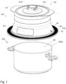
- the electric steam cooker 101 schematically illustrated in the figure 1 is an appliance for heating and/or steaming food, comprising a container 102 for containing the food to be heated and/or cooked, and a steam cooker accessory 104 provided to rest on the container 102.
- the steam cooker accessory 104 is configured to heat and/or steam food contained in the container 102.
- the steam cooker accessory 104 includes a support device 80 provided to rest on the container 102.
- the steam cooker accessory 104 includes an enclosure 100 having an outer side wall 112 and a bottom wall 114.
- the enclosure 100 includes a water reservoir 106 bounded by the outer side wall 112 and the bottom wall 114.
- the reservoir of water 106 communicates with the outside through an upper opening 100a of the enclosure 100.
- the steam cooker accessory 104 comprises a removable cover 103 which closes the enclosure 100 at its upper opening 100a.
- the cover 103 is movable between an open position of the enclosure 100 where the water reservoir 106 is accessible from the outside for filling with water and a closed position of the enclosure 100.
- the steam cooker accessory 104 comprises a steam generator 105 supplying steam to the enclosure 100.
- the support device 80 is provided to carry the steam generator 105.
- the steam generator 105 has a steam production chamber 120.
- the water reservoir 106 supplies water to steam generating chamber 120 by gravity.
- the water tank 106 communicates via a water supply inlet 121 with the steam production chamber 120.
- THE water tank 106 communicates with the steam production chamber 120 by two water supply inlets 121.
- the water tank 106 has a bottom 108 flowing towards the two water supply inlets 121.
- the bottom 108 is formed by the bottom wall 114 of the enclosure 100.
- the steam production chamber 120 comprises a heating device 150 to transform the water present in the steam production chamber 120 into steam.
- the heating device 150 comprises a heating pad 151.
- the heating device 150 can in particular comprise a heating element placed under a heat diffusion plate and/or in a heating plate. heat diffusion forming at least part of the bottom of the steam generating chamber 120.
- the steam production chamber 120 is connected to a steam distribution outlet 115 formed in a lower part 110 of the steam generator 105.
- the steam production chamber 120 communicates with a steam evacuation outlet 122 arranged higher than the water supply inlet 121.
- the steam discharge outlet 122 communicates via a conduit 125 with the steam distribution outlet 115.
- the conduit 125 is vertical.
- the conduit 125 can be descending without necessarily being vertical.
- conduit 125 has no baffles. In other words, conduit 125 descends continuously, without necessarily being straight.
- the steam generator 105 has a bottom wall 113 in which the steam distribution outlet 115 is formed.
- the steam production chamber 120 is arranged in the steam generator 105 at a distance from the bottom wall 113.
- the steam cooker accessory 104 comprises a technical compartment 200 arranged below the enclosure 100 and located between the bottom wall 114 of the enclosure 100 and the bottom wall 113. As seen in figures 1 to 3 , THE technical compartment 200 has an outer annular wall 210 extending from a relatively narrow cylindrical neck portion to a relatively wide lower end.
- the steam cooker accessory 104 comprises a control and display device 300 arranged in the technical compartment 200.
- the control and display device 300 comprises an electronic control unit (not shown in the figures) presenting a control screen and display 320 which is visible on an outer face 220 of the outer annular wall 210. More specifically, the control and display device 300 is arranged inside the technical compartment 200 in a hermetic and sealed manner, which makes it possible both to guarantee the tightness of the electronic components inside the control and display device 300 and to prevent water condensation on the control and display screen 320.
- the lower wall 113 is assembled with the outer annular wall 210 and the bottom wall 114, for example by screwing, by welding, by clipping or by overmoulding.
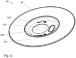
- the support device 80 comprises a support wall 801 disposed below the lower wall 113 and carrying the steam generator 105.
- the support wall 801 comprises a lower face 81 provided to rest on the container 102.
- the face 81 has a support zone 81a configured to come to rest on an upper edge 102a of the container 102.
- the bearing zone 81a is planar and annular.
- the support wall 801 is produced by a metal wall coated with silicone at least on the support zone 81a of the lower face 81. In the embodiment example illustrated in the figures 1 to 6 , the support wall 801 is entirely coated with silicone.
- the support wall 801 thus comprises a metal stiffening structure. As clearly visible on the figures 2 and 3 , the metal stiffening structure extends under the steam generator 105.
- the support wall 801 is circular in shape.
- the support wall 801 can be shaped, for example, rectangular, square, hexagonal, oval, etc. to better adapt to containers of different shapes.
- the support wall 801 has an upper face 82 opposite the lower face 81.
- the upper face 82 has an annular zone 82a surrounding the steam generator 105.
- the annular zone 82a is flat.
- the annular zone 82a is provided with a plurality of protrusions 82b projecting from the upper face 82, allowing the user to firmly grasp the support wall 801.
- the support wall 801 comprises a steam distribution orifice 805 through which the steam distribution outlet 115 passes.
- the steam distribution outlet 115 is formed in the lower wall 113.
- the lower wall 113 is connected to the outlet of evacuation of steam 122 through conduit 125 extending on either side of bottom wall 114 of enclosure 100.
- the steam distribution outlet 115 comes from conduit 125 passing through the lower wall 113 and the support wall 801.
- the steam distribution orifice 805 has an oblong shape.
- the support wall 801 is removably mounted relative to the steam generator 105.
- the support device 80 comprises a fixing nut 802 carrying the support wall 801 and movable between a locked position in which the wall of support 801 is fixed to the bottom wall 113 of the steam generator 105 and an unlocked position in which the support wall 801 can be removed from the bottom wall 113.
- the fixing nut 802 is configured to pass through a central opening 806 of the support wall 801 and come to cooperate with the lower wall 113 to perform the locking and unlocking of the support wall 801.
- the fixing nut 802 is held on the bottom wall 113 by a bayonet connection.
- the support device 80 comprises a washer 803 placed between the fixing nut 802 and the bearing wall 801.
- the metal stiffening structure extends around the central opening 806 and the steam distribution orifice 805.
- the support wall 801 can be fixed to the lower wall 113 by a magnet system which is sized to be functional in a high temperature environment.
- the support device 80 comprises at least one steam exhaust orifice 90 configured to put the cooking enclosure 20 and the outside of the steam cooker accessory 104 in communication. More particularly, the steam exhaust orifice 90 is formed by the fixing nut 802 passing through the central opening 806.
- the support wall 801 has a central cavity 804 in which the central opening 806 and the steam distribution orifice 805 are formed, and in which the fixing nut 802 is housed when the support wall 801 is locked to the bottom wall 113.
- the steam cooker accessory 104 has at least one vent 118 formed between the support wall 801 and the steam generator 105 and provided to place the steam exhaust orifice 90 in communication with the exterior of the accessory steam cooker 104.
- the steam exhaust port 90 is connected to the vent 118 by an exhaust circuit 807, better visible on the figure 6 .
- the exhaust circuit 807 is delimited by the lower wall 113 and two side walls 807a, 807b, the two side walls 807a, 807b being arranged in parallel and spaced apart from each other on the upper face 82 of the wall. support 801.
- the support device 80 provides two exhaust circuits 807 respectively connecting two vents 118 to the steam exhaust orifice 90.
- the two exhaust circuits 807 are arranged perpendicular to one another.
- the support device 80 may include several steam exhaust ports 90.
- the 101 Electric Steamer shown in the figure 1 and the steamer attachment 104 shown in the figures 1 to 6 function and use as follows.
- the user places the steam cooker accessory 104 on the container 102 after having placed the food in the container 102.
- the support device 80 carrying the steam generator 105 rests on the upper edge 102a of the container 102 to form the enclosure for cooking 20.
- the user removes the cover 103 and fills the water tank 106 through the upper opening 100a of the enclosure 100.
- the water flows through the two water supply inlets 121 into the chamber steam generator 120.
- the user fills the water tank 106 to a level sufficiently below the steam exhaust outlet 122, to prevent water from reaching the steam exhaust outlet 122 and flows through conduit 125.
- the user then turns on the heating device 150 by pressing the control and display screen 320.
- the temperature of the water present in the steam production chamber 120 rises until steam is produced.
- the steam produced in the steam generating chamber 120 escapes through the steam evacuation outlet 122 to reach the steam distribution outlet 115 by descending through the conduit 125.
- the steam leaving the steam distribution outlet 115 spreads in the cooking enclosure 20 of the container 102 to heat and/or cook the food.
- the steam escapes first through the steam escape orifice 90 made in the fixing nut 802, then through the two exhaust circuits 807 and finally through the two vents 118 before reaching the outside of the steamer accessory 104.
- the steam cooker accessory 104 thus produced has the advantage of having a support wall 801 which is both solid thanks to a metal stiffening structure and resistant to high temperatures thanks to a silicone coating.
- the silicone coating also makes it possible to remedy any faults in contact between the upper edge 102a of the container 102 and the face. bottom 81 of the support wall 801.
- such a construction provides sealing between the lower face 81 of the support wall 801 and the upper edge 102a of the container 102.
- such a construction makes it possible to guarantee a good adhesion between the support wall 801 and the container 102, which drastically reduces the risk of the steamer accessory slipping on the container.
- the support wall 801 comprises a metal stiffening structure coated with silicone.
- the metal stiffening structure is composed of a first steel wire frame 801a and a second steel wire frame 801b.
- the first and second steel wire reinforcements 801a, 801b are concentric and each have a frame of substantially square shape.
- the first steel wire frame 801a is arranged inside the second steel wire frame 801b, with an angular offset of 45 degrees.
- the second steel wire frame 801b is arranged so that the two exhaust circuits 807 each extend along a diagonal of the second steel wire frame 801b.
- Such a configuration has the advantage of having a construction that is both light and rigid.
- the metal stiffening structure extends around the central opening 806 and the steam distribution orifice 805.
- the metal stiffening structure extends under the steam generator 105.
- the metal stiffening structure comprises a plurality of metal reinforcements.
- Each metal reinforcement can have any type of shape and size.
- the metal stiffening structure may include at least one metal frame configured to support the steam generator 105 when the support device 80 rests on the container 102.
Claims (14)
- Dampfkocherzubehör (104) zum Erhitzen und/oder Dampfen von Lebensmitteln, die in einem Behälter (102) enthalten sind, wobei das Dampfkocherzubehör (104) einen Dampfgenerator (105) umfasst, der eine Dampfproduktionskammer (120) umfasst, die mit einem Dampfverteilungsausgang (115) verbunden ist, der in einem unteren Teil (110) des Dampfgenerators (105) eingerichtet ist, wobei das Dampfkocherzubehör (104) eine Stützvorrichtung (80) umfasst, die den Dampfgenerator (105) trägt und dazu vorgesehen ist, auf dem Behälter (102) aufzuliegen, wobei die Stützvorrichtung (80) eine Auflagewand (801) umfasst, die den Dampfgenerator (105) trägt, wobei die Auflagewand (801) eine untere Seite (81) umfasst, die einen Auflagebereich (81a) aufweist, der dazu vorgesehen ist, auf dem Behälter (102) aufzuliegen, wobei mindestens der Auflagebereich (81a) der unteren Seite (81) aus Silikon hergestellt ist, dadurch gekennzeichnet, dass die Auflagewand (801) in Bezug auf den Dampfgenerator (105) auf abnehmbare Weise angebracht ist, dadurch, dass die Auflagewand (801) eine metallische Versteifungsstruktur umfasst, und dadurch, dass die metallische Versteifungsstruktur sich unter dem Dampfgenerator (105) erstreckt.
- Dampfkocherzubehör (104) nach Anspruch 1, dadurch gekennzeichnet, dass die metallische Versteifungsstruktur eine metallische Wand ist, die mindestens auf dem Auflagebereich (81a) der unteren Seite (81) mit Silikon beschichtet ist.
- Dampfkocherzubehör (104) nach Anspruch1, dadurch gekennzeichnet, dass die metallische Versteifungsstruktur mindestens ein Gestell aus Metalldraht umfasst.
- Dampfkocherzubehör (104) nach einem der Ansprüche 1 bis 3, dadurch gekennzeichnet, dass die metallische Versteifungsstruktur vollständig mit Silikon beschichtet ist.
- Dampfkocherzubehör (104) nach einem der Ansprüche 1 bis 4, dadurch gekennzeichnet, dass die Stützvorrichtung (80) eine Befestigungsmutter (802) umfasst, die die Auflagewand (801) trägt und beweglich ist zwischen einer verriegelten Position, in der die Auflagewand (801) am Dampfgenerator (105) befestigt ist, und einer entriegelten Position, in der die Auflagewand (801) vom Dampfkocherzubehör (104) demontiert werden kann.
- Dampfkocherzubehör (104) nach Anspruch 5, dadurch gekennzeichnet, dass die Stützfvorrichtung (80) eine Unterlegscheibe (803) umfasst, die zwischen der Befestigungsmutter (802) und der Auflagewand (801) angeordnet ist.
- Dampfkocherzubehör (104) nach einem der Ansprüche 5 bis 6, dadurch gekennzeichnet, dass die Befestigungsmutter (802) über eine Bajonettverbindung mit dem Dampfgenerator (105) verbunden ist.
- Dampfkocherzubehör (104) nach einem der Ansprüche 1 bis 7, dadurch gekennzeichnet, dass die Stützvorrichtung (80) mindestens eine Dampfaustrittsöffnung (90) umfasst, die dazu ausgelegt ist, eine Kochkammer (20) und die Außenseite des Dampfkocherzubehörs (104) in Verbindung zu setzen, wobei die Kochkammer (20) durch die Auflagewand (801) und den Behälter (102) begrenzt wird.
- Dampfkocherzubehör (104) nach den Ansprüchen 5 und 8, dadurch gekennzeichnet, dass die Dampfaustrittsöffnung (90) die Befestigungsmutter (802) durchquert.
- Dampfkocherzubehör (104) nach einem der Ansprüche 5 bis 9, dadurch gekennzeichnet, dass die Auflagewand (801) auf der unteren Seite (81) einen mittleren Hohlraum (804) aufweist, in dem die Befestigungsmutter (802) aufgenommen ist.
- Dampfkocherzubehör (104) nach einem der Ansprüche 1 bis 10, dadurch gekennzeichnet, dass der Dampfgenerator (105) eine untere Wand (113) umfasst, in der der Dampfaustrittsausgang (115) gebildet ist, und dadurch, dass die Auflagewand (801) unterhalb der unteren Wand (113) eingerichtet ist und eine Dampfverteilungsöffnung (805) umfasst, die vom Dampfverteilungsausgang (115) durchquert wird.
- Dampfkocherzubehör (104) nach einem der Ansprüche 1 bis 11, dadurch gekennzeichnet, dass die Auflagewand (801) eine kreisförmige Form besitzt.
- Dampfkocherzubehör (104) nach einem der Ansprüche 1 bis 11, dadurch gekennzeichnet, dass die Auflagewand (801) eine rechteckige Form besitzt.
- Elektrischer Dampfkocher (101), umfassend einen Behälter (102) zum Enthalten der zu erhitzenden und/oder zu kochenden Lebensmittel und ein Dampfkocherzubehör (104), das dazu vorgesehen ist, auf dem Behälter (102) aufzuliegen und die im Behälter (102) enthaltenen Lebensmittel zu erhitzen und/oder zu dampfen, dadurch gekennzeichnet, dass das Dampfkocherzubehör (104) mit einem der Ansprüche 1 bis 13 konform ist.
Applications Claiming Priority (3)
| Application Number | Priority Date | Filing Date | Title |
|---|---|---|---|
| FR1872525A FR3089398B1 (fr) | 2018-12-07 | 2018-12-07 | Accessoire cuiseur vapeur avec dispositif de support revetu en silicone |
| FR1902580A FR3089400B1 (fr) | 2018-12-07 | 2019-03-13 | Accessoire cuiseur vapeur avec dispositif de support revetu en silicone |
| PCT/EP2019/083889 WO2020115245A1 (fr) | 2018-12-07 | 2019-12-05 | Accessoire cuiseur vapeur avec dispositif de support revetu en silicone |
Publications (3)
| Publication Number | Publication Date |
|---|---|
| EP3890568A1 EP3890568A1 (de) | 2021-10-13 |
| EP3890568C0 EP3890568C0 (de) | 2023-08-23 |
| EP3890568B1 true EP3890568B1 (de) | 2023-08-23 |
Family
ID=66530173
Family Applications (1)
| Application Number | Title | Priority Date | Filing Date |
|---|---|---|---|
| EP19813548.5A Active EP3890568B1 (de) | 2018-12-07 | 2019-12-05 | Dämpferzubehör mit einer silikonbeschichteten stützvorrichtung |
Country Status (3)
| Country | Link |
|---|---|
| EP (1) | EP3890568B1 (de) |
| CN (1) | CN111281127B (de) |
| FR (2) | FR3089398B1 (de) |
Family Cites Families (17)
| Publication number | Priority date | Publication date | Assignee | Title |
|---|---|---|---|---|
| FR2161447A5 (de) * | 1971-11-25 | 1973-07-06 | Tournus Manuf Metallurg | |
| US4053295A (en) * | 1975-09-08 | 1977-10-11 | Keinosuke Miyauchi | Method of making a cooking utensil lid |
| GB2302263A (en) * | 1995-06-21 | 1997-01-15 | Kwei Tang Chang | Cover for cooking apparatus |
| FR2786083B1 (fr) * | 1998-11-19 | 2001-01-05 | Seb Sa | Cuiseur a vapeur a remplissage lateral d'eau |
| CN1140220C (zh) * | 2001-08-15 | 2004-03-03 | 广州市越秀日达有限公司 | 一种锅盖 |
| CN2558302Y (zh) * | 2002-06-27 | 2003-07-02 | 广州市越秀日达有限公司 | 一种发声锅盖 |
| CN201088481Y (zh) * | 2007-10-31 | 2008-07-23 | 苏州冠纶电子科技有限公司 | 耐高温透明硅胶锅盖 |
| CN101292840B (zh) * | 2008-06-17 | 2010-06-02 | 熊进 | 一种硅胶玻璃盖的制造方法 |
| CN101869437A (zh) * | 2009-04-22 | 2010-10-27 | 胡程韶 | 一种硅胶圈组合盖及其制作方法 |
| CN202086306U (zh) * | 2011-05-23 | 2011-12-28 | 戴结 | 一种多功能双层玻璃锅盖 |
| FR3014662B1 (fr) * | 2013-12-13 | 2016-02-05 | Seb Sa | Accessoire de production de vapeur pour chauffer et/ou cuire a la vapeur des aliments contenus dans un recipient |
| FR3014664B1 (fr) * | 2013-12-13 | 2016-02-05 | Seb Sa | Appareil electrique de chauffage et/ou de cuisson d'aliments a la vapeur |
| FR3051647B1 (fr) * | 2016-05-31 | 2018-06-01 | Seb S.A. | Accessoire cuiseur vapeur pour chauffer et/ou cuire a la vapeur des aliments contenus dans un recipient |
| FR3060288B1 (fr) * | 2016-12-20 | 2019-05-31 | Seb S.A. | Cuiseur vapeur comportant un recipient et un accessoire pour chauffer et/ou cuire a la vapeur des aliments contenus dans le recipient |
| FR3060287B1 (fr) * | 2016-12-20 | 2019-07-26 | Seb S.A. | Accessoire cuiseur vapeur perfectionne pour chauffer et/ou cuire a la vapeur des aliments contenus dans un recipient |
| FR3060286B1 (fr) | 2016-12-20 | 2019-07-26 | Seb S.A. | Accessoire cuiseur vapeur modulaire pour chauffer et/ou cuire a la vapeur des aliments contenus dans un recipient |
| CN207544927U (zh) * | 2017-04-21 | 2018-06-29 | 佛山市顺德区美的电热电器制造有限公司 | 烹饪厨具盖体、烹饪厨具盖体组件和烹饪厨具 |
-
2018
- 2018-12-07 FR FR1872525A patent/FR3089398B1/fr active Active
-
2019
- 2019-03-13 FR FR1902580A patent/FR3089400B1/fr active Active
- 2019-12-05 CN CN201911232815.1A patent/CN111281127B/zh active Active
- 2019-12-05 EP EP19813548.5A patent/EP3890568B1/de active Active
Also Published As
| Publication number | Publication date |
|---|---|
| CN111281127A (zh) | 2020-06-16 |
| EP3890568A1 (de) | 2021-10-13 |
| FR3089398B1 (fr) | 2021-04-02 |
| EP3890568C0 (de) | 2023-08-23 |
| FR3089398A1 (fr) | 2020-06-12 |
| FR3089400A1 (fr) | 2020-06-12 |
| FR3089400B1 (fr) | 2022-01-07 |
| CN111281127B (zh) | 2023-05-23 |
Similar Documents
| Publication | Publication Date | Title |
|---|---|---|
| EP3558071B1 (de) | Modulares dampfgarerzubehör zum dampferhitzen und/oder -garen von lebensmitteln in einem behälter | |
| EP3558069B1 (de) | Zubehör für dampferwärmen und/oder dampfgaren von speisen und dämpfer mit einem behälter und einem zubehör für dampferwärmen und/oder dampfgaren von speisen in dem behälter | |
| EP3463002B1 (de) | Dämpferzubehör zum dampferhitzen und/oder -dämpfen von lebensmitteln in einem behälter | |
| EP3310216B1 (de) | Dampfgarerzubehör zum dampferhitzen und/oder dampfgaren von lebensmitteln in einem behälter | |
| WO2019149573A1 (fr) | Appareil de cuisson electrique muni d'un panier a vapeur | |
| EP2805650A1 (de) | Kochtopf, der ein dichtes Gehäuse umfasst | |
| FR3072553A1 (fr) | Autocuiseur a fenetre d'extrusion | |
| WO2020115245A1 (fr) | Accessoire cuiseur vapeur avec dispositif de support revetu en silicone | |
| EP3890568B1 (de) | Dämpferzubehör mit einer silikonbeschichteten stützvorrichtung | |
| EP1154714B1 (de) | Wasserkocher mit heizplatte aus metall | |
| EP3890569B1 (de) | Dampfkocherzubehör mit stützvorrichtung mit rippen | |
| EP3890565B1 (de) | Dampfkocher-zubehör mit abnehmbarem stecker | |
| EP3450617B1 (de) | Bügelvorrichtung umfassend eine basis verbunden mittels eines kabels mit einem bügeleisen | |
| EP3450619B1 (de) | Bügeleisen, das ein gehäuse, einen heizkörper und eine zwischen dem heizkörper und dem gehäuse eingebaute funktionelle platine umfasst | |
| EP3890564B1 (de) | Dampfkocherzubehör mit doppelter turbokrone | |
| EP1504706B1 (de) | Elektrisches Kochgerät mit einem Stromversorgungssockel | |
| EP3890566A1 (de) | Dampfkocherzubehör mit versetztem dampfrohr | |
| FR2614400A1 (fr) | Appareil autonome de cuisson par rayonnement | |
| FR2858534A1 (fr) | Recipient de cuisson pour socle chauffant ou socle d'alimentation electrique | |
| FR3089402A1 (fr) | Accessoire cuiseur vapeur avec couvercle verrouillable | |
| FR2858533A1 (fr) | Appareil electrique de cuisson comportant un socle d'alimentation electrique |
Legal Events
| Date | Code | Title | Description |
|---|---|---|---|
| STAA | Information on the status of an ep patent application or granted ep patent |
Free format text: STATUS: UNKNOWN |
|
| STAA | Information on the status of an ep patent application or granted ep patent |
Free format text: STATUS: THE INTERNATIONAL PUBLICATION HAS BEEN MADE |
|
| STAA | Information on the status of an ep patent application or granted ep patent |
Free format text: STATUS: THE INTERNATIONAL PUBLICATION HAS BEEN MADE |
|
| PUAI | Public reference made under article 153(3) epc to a published international application that has entered the european phase |
Free format text: ORIGINAL CODE: 0009012 |
|
| STAA | Information on the status of an ep patent application or granted ep patent |
Free format text: STATUS: REQUEST FOR EXAMINATION WAS MADE |
|
| 17P | Request for examination filed |
Effective date: 20210610 |
|
| AK | Designated contracting states |
Kind code of ref document: A1 Designated state(s): AL AT BE BG CH CY CZ DE DK EE ES FI FR GB GR HR HU IE IS IT LI LT LU LV MC MK MT NL NO PL PT RO RS SE SI SK SM TR |
|
| DAV | Request for validation of the european patent (deleted) | ||
| DAX | Request for extension of the european patent (deleted) | ||
| GRAP | Despatch of communication of intention to grant a patent |
Free format text: ORIGINAL CODE: EPIDOSNIGR1 |
|
| STAA | Information on the status of an ep patent application or granted ep patent |
Free format text: STATUS: GRANT OF PATENT IS INTENDED |
|
| INTG | Intention to grant announced |
Effective date: 20230328 |
|
| GRAS | Grant fee paid |
Free format text: ORIGINAL CODE: EPIDOSNIGR3 |
|
| GRAA | (expected) grant |
Free format text: ORIGINAL CODE: 0009210 |
|
| STAA | Information on the status of an ep patent application or granted ep patent |
Free format text: STATUS: THE PATENT HAS BEEN GRANTED |
|
| AK | Designated contracting states |
Kind code of ref document: B1 Designated state(s): AL AT BE BG CH CY CZ DE DK EE ES FI FR GB GR HR HU IE IS IT LI LT LU LV MC MK MT NL NO PL PT RO RS SE SI SK SM TR |
|
| REG | Reference to a national code |
Ref country code: GB Ref legal event code: FG4D Free format text: NOT ENGLISH |
|
| REG | Reference to a national code |
Ref country code: CH Ref legal event code: EP |
|
| REG | Reference to a national code |
Ref country code: IE Ref legal event code: FG4D Free format text: LANGUAGE OF EP DOCUMENT: FRENCH |
|
| REG | Reference to a national code |
Ref country code: DE Ref legal event code: R096 Ref document number: 602019035761 Country of ref document: DE |
|
| U01 | Request for unitary effect filed |
Effective date: 20230920 |
|
| U07 | Unitary effect registered |
Designated state(s): AT BE BG DE DK EE FI FR IT LT LU LV MT NL PT SE SI Effective date: 20230928 |
|
| U20 | Renewal fee paid [unitary effect] |
Year of fee payment: 5 Effective date: 20231123 |
|
| PG25 | Lapsed in a contracting state [announced via postgrant information from national office to epo] |
Ref country code: GR Free format text: LAPSE BECAUSE OF FAILURE TO SUBMIT A TRANSLATION OF THE DESCRIPTION OR TO PAY THE FEE WITHIN THE PRESCRIBED TIME-LIMIT Effective date: 20231124 |
|
| PGFP | Annual fee paid to national office [announced via postgrant information from national office to epo] |
Ref country code: GB Payment date: 20231221 Year of fee payment: 5 |
|
| PG25 | Lapsed in a contracting state [announced via postgrant information from national office to epo] |
Ref country code: IS Free format text: LAPSE BECAUSE OF FAILURE TO SUBMIT A TRANSLATION OF THE DESCRIPTION OR TO PAY THE FEE WITHIN THE PRESCRIBED TIME-LIMIT Effective date: 20231223 |
|
| PG25 | Lapsed in a contracting state [announced via postgrant information from national office to epo] |
Ref country code: RS Free format text: LAPSE BECAUSE OF FAILURE TO SUBMIT A TRANSLATION OF THE DESCRIPTION OR TO PAY THE FEE WITHIN THE PRESCRIBED TIME-LIMIT Effective date: 20230823 Ref country code: NO Free format text: LAPSE BECAUSE OF FAILURE TO SUBMIT A TRANSLATION OF THE DESCRIPTION OR TO PAY THE FEE WITHIN THE PRESCRIBED TIME-LIMIT Effective date: 20231123 Ref country code: IS Free format text: LAPSE BECAUSE OF FAILURE TO SUBMIT A TRANSLATION OF THE DESCRIPTION OR TO PAY THE FEE WITHIN THE PRESCRIBED TIME-LIMIT Effective date: 20231223 Ref country code: HR Free format text: LAPSE BECAUSE OF FAILURE TO SUBMIT A TRANSLATION OF THE DESCRIPTION OR TO PAY THE FEE WITHIN THE PRESCRIBED TIME-LIMIT Effective date: 20230823 Ref country code: GR Free format text: LAPSE BECAUSE OF FAILURE TO SUBMIT A TRANSLATION OF THE DESCRIPTION OR TO PAY THE FEE WITHIN THE PRESCRIBED TIME-LIMIT Effective date: 20231124 |
|
| PG25 | Lapsed in a contracting state [announced via postgrant information from national office to epo] |
Ref country code: PL Free format text: LAPSE BECAUSE OF FAILURE TO SUBMIT A TRANSLATION OF THE DESCRIPTION OR TO PAY THE FEE WITHIN THE PRESCRIBED TIME-LIMIT Effective date: 20230823 |
|
| PG25 | Lapsed in a contracting state [announced via postgrant information from national office to epo] |
Ref country code: ES Free format text: LAPSE BECAUSE OF FAILURE TO SUBMIT A TRANSLATION OF THE DESCRIPTION OR TO PAY THE FEE WITHIN THE PRESCRIBED TIME-LIMIT Effective date: 20230823 |
|
| PG25 | Lapsed in a contracting state [announced via postgrant information from national office to epo] |
Ref country code: SM Free format text: LAPSE BECAUSE OF FAILURE TO SUBMIT A TRANSLATION OF THE DESCRIPTION OR TO PAY THE FEE WITHIN THE PRESCRIBED TIME-LIMIT Effective date: 20230823 Ref country code: RO Free format text: LAPSE BECAUSE OF FAILURE TO SUBMIT A TRANSLATION OF THE DESCRIPTION OR TO PAY THE FEE WITHIN THE PRESCRIBED TIME-LIMIT Effective date: 20230823 Ref country code: ES Free format text: LAPSE BECAUSE OF FAILURE TO SUBMIT A TRANSLATION OF THE DESCRIPTION OR TO PAY THE FEE WITHIN THE PRESCRIBED TIME-LIMIT Effective date: 20230823 Ref country code: CZ Free format text: LAPSE BECAUSE OF FAILURE TO SUBMIT A TRANSLATION OF THE DESCRIPTION OR TO PAY THE FEE WITHIN THE PRESCRIBED TIME-LIMIT Effective date: 20230823 Ref country code: SK Free format text: LAPSE BECAUSE OF FAILURE TO SUBMIT A TRANSLATION OF THE DESCRIPTION OR TO PAY THE FEE WITHIN THE PRESCRIBED TIME-LIMIT Effective date: 20230823 |