EP3890568B1 - Steamer accessory with silicone-coated support device - Google Patents
Steamer accessory with silicone-coated support device Download PDFInfo
- Publication number
- EP3890568B1 EP3890568B1 EP19813548.5A EP19813548A EP3890568B1 EP 3890568 B1 EP3890568 B1 EP 3890568B1 EP 19813548 A EP19813548 A EP 19813548A EP 3890568 B1 EP3890568 B1 EP 3890568B1
- Authority
- EP
- European Patent Office
- Prior art keywords
- steam
- steamer accessory
- container
- wall
- accessory
- Prior art date
- Legal status (The legal status is an assumption and is not a legal conclusion. Google has not performed a legal analysis and makes no representation as to the accuracy of the status listed.)
- Active
Links
- 229920001296 polysiloxane Polymers 0.000 title claims description 10
- 239000002184 metal Substances 0.000 claims description 29
- 238000010438 heat treatment Methods 0.000 claims description 24
- 238000009826 distribution Methods 0.000 claims description 22
- 238000010025 steaming Methods 0.000 claims description 16
- 238000010411 cooking Methods 0.000 claims description 12
- 238000004891 communication Methods 0.000 claims description 4
- XLYOFNOQVPJJNP-UHFFFAOYSA-N water Substances O XLYOFNOQVPJJNP-UHFFFAOYSA-N 0.000 description 21
- 238000010276 construction Methods 0.000 description 15
- 238000004519 manufacturing process Methods 0.000 description 11
- 229910000831 Steel Inorganic materials 0.000 description 7
- 239000010959 steel Substances 0.000 description 7
- 230000002787 reinforcement Effects 0.000 description 4
- 239000004447 silicone coating Substances 0.000 description 4
- 238000009792 diffusion process Methods 0.000 description 2
- 238000007789 sealing Methods 0.000 description 2
- 239000007787 solid Substances 0.000 description 2
- 238000004140 cleaning Methods 0.000 description 1
- 238000009833 condensation Methods 0.000 description 1
- 230000005494 condensation Effects 0.000 description 1
- 230000008878 coupling Effects 0.000 description 1
- 238000010168 coupling process Methods 0.000 description 1
- 238000005859 coupling reaction Methods 0.000 description 1
- 230000007547 defect Effects 0.000 description 1
- 230000005484 gravity Effects 0.000 description 1
- 238000000034 method Methods 0.000 description 1
- 238000012986 modification Methods 0.000 description 1
- 230000004048 modification Effects 0.000 description 1
- 238000003825 pressing Methods 0.000 description 1
- 238000007665 sagging Methods 0.000 description 1
- 229920006395 saturated elastomer Polymers 0.000 description 1
- 238000006467 substitution reaction Methods 0.000 description 1
- 238000003466 welding Methods 0.000 description 1
Images


Classifications
-
- A—HUMAN NECESSITIES
- A47—FURNITURE; DOMESTIC ARTICLES OR APPLIANCES; COFFEE MILLS; SPICE MILLS; SUCTION CLEANERS IN GENERAL
- A47J—KITCHEN EQUIPMENT; COFFEE MILLS; SPICE MILLS; APPARATUS FOR MAKING BEVERAGES
- A47J27/00—Cooking-vessels
- A47J27/04—Cooking-vessels for cooking food in steam; Devices for extracting fruit juice by means of steam ; Vacuum cooking vessels
-
- A—HUMAN NECESSITIES
- A47—FURNITURE; DOMESTIC ARTICLES OR APPLIANCES; COFFEE MILLS; SPICE MILLS; SUCTION CLEANERS IN GENERAL
- A47J—KITCHEN EQUIPMENT; COFFEE MILLS; SPICE MILLS; APPARATUS FOR MAKING BEVERAGES
- A47J36/00—Parts, details or accessories of cooking-vessels
- A47J36/34—Supports for cooking-vessels
-
- A—HUMAN NECESSITIES
- A47—FURNITURE; DOMESTIC ARTICLES OR APPLIANCES; COFFEE MILLS; SPICE MILLS; SUCTION CLEANERS IN GENERAL
- A47J—KITCHEN EQUIPMENT; COFFEE MILLS; SPICE MILLS; APPARATUS FOR MAKING BEVERAGES
- A47J27/00—Cooking-vessels
- A47J27/04—Cooking-vessels for cooking food in steam; Devices for extracting fruit juice by means of steam ; Vacuum cooking vessels
- A47J2027/043—Cooking-vessels for cooking food in steam; Devices for extracting fruit juice by means of steam ; Vacuum cooking vessels for cooking food in steam
Definitions
- the present invention relates to the technical field of appliances and devices for producing steam for heating and/or steaming food.
- the present invention relates more particularly to steam cooker accessories for heating and/or steaming food contained in a container.
- the present invention also relates to appliances for heating and/or steaming food, comprising a container associated with a steam generating device forming such a steam cooker accessory.
- the steam cooker accessory comprises a steam generator comprising a steam production chamber connected to a steam distribution outlet provided in a lower part of the steam generator.
- the steam cooker accessory comprises a support device carrying the steam generator and provided to rest on the container.
- the support device comprises a support wall carrying the steam generator.
- the support wall has an underside.
- such a steam cooker accessory has the disadvantage of having a support wall having an underside which is directly exposed to a high temperature environment.
- the support wall of the support device can reach a high temperature during use, which leads to dangerous situations for the user.
- the user risks being burned by inadvertently touching the very hot support wall.
- a very hot support wall can also cause damage to an unprotected work surface.
- some recipes require a cooking step, for example baking, before steaming. In this case, the container resulting from this cooking step could have a very high temperature, which could damage the support wall of the support device which comes to rest on the container.
- such a steam cooker accessory has the disadvantage of causing an involuntary steam leak between the support wall and an upper edge of the container, when the underside of the support wall has a poor surface condition or when the flatness of the upper edge of the container is poor.
- the underside of the support wall is exposed to a humid environment linked to the presence of steam.
- the support wall could slide on the upper edge of the container when the container is placed on an inclined work surface or when the upper edge of the container is slightly inclined.
- An apparatus according to the preamble of claim 1 is known from document FR2161447 .
- An object of the present invention is to provide a steamer accessory used with a container for heating and/or steaming food, which can be used safely.
- Another object of the present invention is to provide a steam cooker accessory used with a container for heating and/or steaming food, which makes it possible to better control the escape of steam.
- Another object of the present invention is to provide a steam cooker accessory used with a container for heating and/or steaming food, which has a simple and economical construction.
- Another object of the present invention is to provide a steam cooker accessory used with a container for heating and/or steaming food, which has a robust and durable construction.
- Another object of the present invention is to provide an electric steamer for heating and/or steaming food comprising a container and a steamer accessory which can be used in complete safety.
- Another object of the present invention is to provide an electric steam cooker for heating and/or steaming food comprising a container and a steam cooker accessory which makes it possible to better control the escape of steam.
- Another object of the present invention is to provide an electric steam cooker for heating and/or steaming food comprising a container and a steam cooker accessory which has a simple and economical construction.
- Another object of the present invention is to provide an electric steam cooker for heating and/or steaming food comprising a container and a steam cooker accessory which has a robust and durable construction.
- a steam cooker accessory for heating and/or steam cooking food contained in a container
- the steam cooker accessory comprising a steam generator comprising a steam production chamber connected to a steam distribution outlet formed in a lower part of the steam generator
- the steam cooker accessory comprising a support device carrying the steam generator and designed to rest on the container, the support device comprising a support wall carrying the steam generator, the support wall comprising a lower face having a support zone intended to rest on the container, at least the support zone of the lower face being made of silicone, due to the fact that the support wall is removably mounted relative to the steam generator, that the support wall comprises a metal stiffening structure, and that the metal stiffening structure extends under the steam generator.
- the support wall can be dismantled without call for a tool.
- This arrangement has the advantage of easily dismantling the support wall for cleaning. Such a characteristic also makes it possible to change the support wall so as to be able to better adapt to different types of containers.
- This arrangement makes it possible in particular to avoid sagging of the support device which would be due to exposure to high temperatures encountered, for example, during the dry heating of a cooking vessel carrying the steam cooker accessory.
- the steam cooker accessory thus produced has the advantage of having a support wall which is both solid thanks to a metal stiffening structure and resistant to high temperatures thanks to a silicone coating.
- the silicone coating also makes it possible to remedy any defects in contact between the upper edge of the container and the lower face of the support wall.
- such a construction provides sealing between the lower face of the support wall and the upper edge of the container.
- such a construction makes it possible to guarantee good adhesion between the support wall and the container, which drastically reduces the risk of the steam cooker accessory slipping on the container.
- the metal stiffening structure is a metal wall coated with silicone at least on the bearing zone of the lower face.
- This arrangement has a construction that is easy to implement.
- the metal stiffening structure comprises at least one metal wire reinforcement. This arrangement makes it possible to have a construction that is both light and rigid.
- the metal stiffening structure is entirely coated with silicone.
- This arrangement has a construction that is simple and economical to implement.
- the support device comprises a fixing nut carrying the support wall and movable between a locked position in which the support wall is fixed on the steam generator and an unlocked position in which the support wall can be removed from the steamer accessory.
- the support device comprises a washer disposed between the fixing nut and the bearing wall. This arrangement makes it possible both to ensure a good seal between the fixing nut and the bearing wall, and to reinforce the assembly of the fixing nut on the steam generator.
- the fixing nut is connected to the steam generator by a bayonet connection.
- This arrangement has the advantage of having a quick and easy attachment of the support wall to the lower part of the steam generator.
- the bayonet type coupling is both safe and efficient.
- the support device comprises at least one steam exhaust orifice configured to place a cooking enclosure in communication with the exterior of the steam cooker accessory, the cooking enclosure being delimited by the support wall and the recipient.
- This arrangement makes it possible to better control the escape of steam from the container closed by the steam cooker accessory.
- the steam escape orifice passes through the fixing nut.
- This arrangement has a simple construction to implement.
- the support wall has a central cavity on the underside in which the fixing nut is housed.
- This arrangement presents a compact and economical construction.
- the steam generator comprises a lower wall in which the steam distribution outlet is formed, and the support wall is arranged below the lower wall and comprises a steam distribution orifice through which the steam distribution outlet passes. steam.
- the bearing wall is circular in shape. This arrangement allows the support wall to better adapt to containers whose upper edge is round.
- the support wall is rectangular in shape. This arrangement allows the support wall to better adapt to containers whose upper edge is rectangular.
- an electric steam cooker comprising a container for containing the food to be heated and/or cooked, and a steam cooker accessory provided to rest on the container and to heat and/or steam the food contained in the container according to at least one of the aforementioned characteristics.
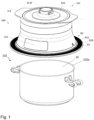
- the electric steam cooker 101 schematically illustrated in the figure 1 is an appliance for heating and/or steaming food, comprising a container 102 for containing the food to be heated and/or cooked, and a steam cooker accessory 104 provided to rest on the container 102.
- the steam cooker accessory 104 is configured to heat and/or steam food contained in the container 102.
- the steam cooker accessory 104 includes a support device 80 provided to rest on the container 102.
- the steam cooker accessory 104 includes an enclosure 100 having an outer side wall 112 and a bottom wall 114.
- the enclosure 100 includes a water reservoir 106 bounded by the outer side wall 112 and the bottom wall 114.
- the reservoir of water 106 communicates with the outside through an upper opening 100a of the enclosure 100.
- the steam cooker accessory 104 comprises a removable cover 103 which closes the enclosure 100 at its upper opening 100a.
- the cover 103 is movable between an open position of the enclosure 100 where the water reservoir 106 is accessible from the outside for filling with water and a closed position of the enclosure 100.
- the steam cooker accessory 104 comprises a steam generator 105 supplying steam to the enclosure 100.
- the support device 80 is provided to carry the steam generator 105.
- the steam generator 105 has a steam production chamber 120.
- the water reservoir 106 supplies water to steam generating chamber 120 by gravity.
- the water tank 106 communicates via a water supply inlet 121 with the steam production chamber 120.
- THE water tank 106 communicates with the steam production chamber 120 by two water supply inlets 121.
- the water tank 106 has a bottom 108 flowing towards the two water supply inlets 121.
- the bottom 108 is formed by the bottom wall 114 of the enclosure 100.
- the steam production chamber 120 comprises a heating device 150 to transform the water present in the steam production chamber 120 into steam.
- the heating device 150 comprises a heating pad 151.
- the heating device 150 can in particular comprise a heating element placed under a heat diffusion plate and/or in a heating plate. heat diffusion forming at least part of the bottom of the steam generating chamber 120.
- the steam production chamber 120 is connected to a steam distribution outlet 115 formed in a lower part 110 of the steam generator 105.
- the steam production chamber 120 communicates with a steam evacuation outlet 122 arranged higher than the water supply inlet 121.
- the steam discharge outlet 122 communicates via a conduit 125 with the steam distribution outlet 115.
- the conduit 125 is vertical.
- the conduit 125 can be descending without necessarily being vertical.
- conduit 125 has no baffles. In other words, conduit 125 descends continuously, without necessarily being straight.
- the steam generator 105 has a bottom wall 113 in which the steam distribution outlet 115 is formed.
- the steam production chamber 120 is arranged in the steam generator 105 at a distance from the bottom wall 113.
- the steam cooker accessory 104 comprises a technical compartment 200 arranged below the enclosure 100 and located between the bottom wall 114 of the enclosure 100 and the bottom wall 113. As seen in figures 1 to 3 , THE technical compartment 200 has an outer annular wall 210 extending from a relatively narrow cylindrical neck portion to a relatively wide lower end.
- the steam cooker accessory 104 comprises a control and display device 300 arranged in the technical compartment 200.
- the control and display device 300 comprises an electronic control unit (not shown in the figures) presenting a control screen and display 320 which is visible on an outer face 220 of the outer annular wall 210. More specifically, the control and display device 300 is arranged inside the technical compartment 200 in a hermetic and sealed manner, which makes it possible both to guarantee the tightness of the electronic components inside the control and display device 300 and to prevent water condensation on the control and display screen 320.
- the lower wall 113 is assembled with the outer annular wall 210 and the bottom wall 114, for example by screwing, by welding, by clipping or by overmoulding.
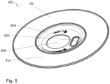
- the support device 80 comprises a support wall 801 disposed below the lower wall 113 and carrying the steam generator 105.
- the support wall 801 comprises a lower face 81 provided to rest on the container 102.
- the face 81 has a support zone 81a configured to come to rest on an upper edge 102a of the container 102.
- the bearing zone 81a is planar and annular.
- the support wall 801 is produced by a metal wall coated with silicone at least on the support zone 81a of the lower face 81. In the embodiment example illustrated in the figures 1 to 6 , the support wall 801 is entirely coated with silicone.
- the support wall 801 thus comprises a metal stiffening structure. As clearly visible on the figures 2 and 3 , the metal stiffening structure extends under the steam generator 105.
- the support wall 801 is circular in shape.
- the support wall 801 can be shaped, for example, rectangular, square, hexagonal, oval, etc. to better adapt to containers of different shapes.
- the support wall 801 has an upper face 82 opposite the lower face 81.
- the upper face 82 has an annular zone 82a surrounding the steam generator 105.
- the annular zone 82a is flat.
- the annular zone 82a is provided with a plurality of protrusions 82b projecting from the upper face 82, allowing the user to firmly grasp the support wall 801.
- the support wall 801 comprises a steam distribution orifice 805 through which the steam distribution outlet 115 passes.
- the steam distribution outlet 115 is formed in the lower wall 113.
- the lower wall 113 is connected to the outlet of evacuation of steam 122 through conduit 125 extending on either side of bottom wall 114 of enclosure 100.
- the steam distribution outlet 115 comes from conduit 125 passing through the lower wall 113 and the support wall 801.
- the steam distribution orifice 805 has an oblong shape.
- the support wall 801 is removably mounted relative to the steam generator 105.
- the support device 80 comprises a fixing nut 802 carrying the support wall 801 and movable between a locked position in which the wall of support 801 is fixed to the bottom wall 113 of the steam generator 105 and an unlocked position in which the support wall 801 can be removed from the bottom wall 113.
- the fixing nut 802 is configured to pass through a central opening 806 of the support wall 801 and come to cooperate with the lower wall 113 to perform the locking and unlocking of the support wall 801.
- the fixing nut 802 is held on the bottom wall 113 by a bayonet connection.
- the support device 80 comprises a washer 803 placed between the fixing nut 802 and the bearing wall 801.
- the metal stiffening structure extends around the central opening 806 and the steam distribution orifice 805.
- the support wall 801 can be fixed to the lower wall 113 by a magnet system which is sized to be functional in a high temperature environment.
- the support device 80 comprises at least one steam exhaust orifice 90 configured to put the cooking enclosure 20 and the outside of the steam cooker accessory 104 in communication. More particularly, the steam exhaust orifice 90 is formed by the fixing nut 802 passing through the central opening 806.
- the support wall 801 has a central cavity 804 in which the central opening 806 and the steam distribution orifice 805 are formed, and in which the fixing nut 802 is housed when the support wall 801 is locked to the bottom wall 113.
- the steam cooker accessory 104 has at least one vent 118 formed between the support wall 801 and the steam generator 105 and provided to place the steam exhaust orifice 90 in communication with the exterior of the accessory steam cooker 104.
- the steam exhaust port 90 is connected to the vent 118 by an exhaust circuit 807, better visible on the figure 6 .
- the exhaust circuit 807 is delimited by the lower wall 113 and two side walls 807a, 807b, the two side walls 807a, 807b being arranged in parallel and spaced apart from each other on the upper face 82 of the wall. support 801.
- the support device 80 provides two exhaust circuits 807 respectively connecting two vents 118 to the steam exhaust orifice 90.
- the two exhaust circuits 807 are arranged perpendicular to one another.
- the support device 80 may include several steam exhaust ports 90.
- the 101 Electric Steamer shown in the figure 1 and the steamer attachment 104 shown in the figures 1 to 6 function and use as follows.
- the user places the steam cooker accessory 104 on the container 102 after having placed the food in the container 102.
- the support device 80 carrying the steam generator 105 rests on the upper edge 102a of the container 102 to form the enclosure for cooking 20.
- the user removes the cover 103 and fills the water tank 106 through the upper opening 100a of the enclosure 100.
- the water flows through the two water supply inlets 121 into the chamber steam generator 120.
- the user fills the water tank 106 to a level sufficiently below the steam exhaust outlet 122, to prevent water from reaching the steam exhaust outlet 122 and flows through conduit 125.
- the user then turns on the heating device 150 by pressing the control and display screen 320.
- the temperature of the water present in the steam production chamber 120 rises until steam is produced.
- the steam produced in the steam generating chamber 120 escapes through the steam evacuation outlet 122 to reach the steam distribution outlet 115 by descending through the conduit 125.
- the steam leaving the steam distribution outlet 115 spreads in the cooking enclosure 20 of the container 102 to heat and/or cook the food.
- the steam escapes first through the steam escape orifice 90 made in the fixing nut 802, then through the two exhaust circuits 807 and finally through the two vents 118 before reaching the outside of the steamer accessory 104.
- the steam cooker accessory 104 thus produced has the advantage of having a support wall 801 which is both solid thanks to a metal stiffening structure and resistant to high temperatures thanks to a silicone coating.
- the silicone coating also makes it possible to remedy any faults in contact between the upper edge 102a of the container 102 and the face. bottom 81 of the support wall 801.
- such a construction provides sealing between the lower face 81 of the support wall 801 and the upper edge 102a of the container 102.
- such a construction makes it possible to guarantee a good adhesion between the support wall 801 and the container 102, which drastically reduces the risk of the steamer accessory slipping on the container.
- the support wall 801 comprises a metal stiffening structure coated with silicone.
- the metal stiffening structure is composed of a first steel wire frame 801a and a second steel wire frame 801b.
- the first and second steel wire reinforcements 801a, 801b are concentric and each have a frame of substantially square shape.
- the first steel wire frame 801a is arranged inside the second steel wire frame 801b, with an angular offset of 45 degrees.
- the second steel wire frame 801b is arranged so that the two exhaust circuits 807 each extend along a diagonal of the second steel wire frame 801b.
- Such a configuration has the advantage of having a construction that is both light and rigid.
- the metal stiffening structure extends around the central opening 806 and the steam distribution orifice 805.
- the metal stiffening structure extends under the steam generator 105.
- the metal stiffening structure comprises a plurality of metal reinforcements.
- Each metal reinforcement can have any type of shape and size.
- the metal stiffening structure may include at least one metal frame configured to support the steam generator 105 when the support device 80 rests on the container 102.
Description
La présente invention concerne le domaine technique des appareils et dispositifs de production de vapeur pour chauffer et/ou cuire des aliments à la vapeur.The present invention relates to the technical field of appliances and devices for producing steam for heating and/or steaming food.
La présente invention concerne plus particulièrement les accessoires cuiseur vapeur pour chauffer et/ou cuire à la vapeur des aliments contenus dans un récipient.The present invention relates more particularly to steam cooker accessories for heating and/or steaming food contained in a container.
La présente invention concerne également les appareils pour chauffer et/ou cuire à la vapeur des aliments, comportant un récipient associé à un dispositif de production de vapeur formant un tel accessoire cuiseur vapeur.The present invention also relates to appliances for heating and/or steaming food, comprising a container associated with a steam generating device forming such a steam cooker accessory.
Il est connu, du document
Cependant, un tel accessoire cuiseur vapeur présente l'inconvénient d'avoir une paroi d'appui ayant une face inférieure qui est directement exposée à un environnement à température élevée. La paroi d'appui du dispositif de support peut atteindre une température importante au cours de l'utilisation, ce qui entraine des situations dangereuses pour l'utilisateur. L'utilisateur risque de se brûler en touchant la paroi d'appui très chaude par inadvertance. Après l'utilisation, une paroi d'appui très chaude risque également de causer des dégâts sur un plan de travail non protégé. Par ailleurs, certaines recettes nécessitent une étape de cuisson, par exemple une cuisson au four, avant la cuisson à la vapeur. En l'occurrence, le récipient issu de cette étape de cuisson pourrait présenter une température très élevée, pouvant détériorer la paroi d'appui du dispositif de support qui vient reposer sur le récipient.However, such a steam cooker accessory has the disadvantage of having a support wall having an underside which is directly exposed to a high temperature environment. The support wall of the support device can reach a high temperature during use, which leads to dangerous situations for the user. The user risks being burned by inadvertently touching the very hot support wall. After use, a very hot support wall can also cause damage to an unprotected work surface. Also, some recipes require a cooking step, for example baking, before steaming. In this case, the container resulting from this cooking step could have a very high temperature, which could damage the support wall of the support device which comes to rest on the container.
En outre, un tel accessoire cuiseur vapeur présente l'inconvénient d'entrainer une fuite de vapeur involontaire entre la paroi d'appui et un bord supérieur du récipient, lorsque la face inférieure de la paroi d'appui présente un mauvais état de surface ou lorsque la planéité du bord supérieur du récipient est mauvaise.In addition, such a steam cooker accessory has the disadvantage of causing an involuntary steam leak between the support wall and an upper edge of the container, when the underside of the support wall has a poor surface condition or when the flatness of the upper edge of the container is poor.
De plus, la face inférieure de la paroi d'appui est exposée à un environnement humide lié à la présence de vapeur. La paroi d'appui pourrait glisser sur le bord supérieur du récipient lorsque le récipient est placé sur un plan de travail incliné ou lorsque le bord supérieur du récipient est légèrement incliné.In addition, the underside of the support wall is exposed to a humid environment linked to the presence of steam. The support wall could slide on the upper edge of the container when the container is placed on an inclined work surface or when the upper edge of the container is slightly inclined.
Un appareil selon le préambule de la revendication 1 est connu du document
Un objet de la présente invention est de proposer un accessoire cuiseur vapeur utilisé avec un récipient pour chauffer et/ou cuire des aliments à la vapeur, qui peut être utilisé en toute sécurité.An object of the present invention is to provide a steamer accessory used with a container for heating and/or steaming food, which can be used safely.
Un autre objet de la présente invention est de proposer un accessoire cuiseur vapeur utilisé avec un récipient pour chauffer et/ou cuire des aliments à la vapeur, qui permet de mieux contrôler l'échappement de vapeur.Another object of the present invention is to provide a steam cooker accessory used with a container for heating and/or steaming food, which makes it possible to better control the escape of steam.
Un autre objet de la présente invention est de proposer un accessoire cuiseur vapeur utilisé avec un récipient pour chauffer et/ou cuire des aliments à la vapeur, qui présente une construction simple et économique.Another object of the present invention is to provide a steam cooker accessory used with a container for heating and/or steaming food, which has a simple and economical construction.
Un autre objet de la présente invention est de proposer un accessoire cuiseur vapeur utilisé avec un récipient pour chauffer et/ou cuire des aliments à la vapeur, qui présente une construction robuste et pérenne.Another object of the present invention is to provide a steam cooker accessory used with a container for heating and/or steaming food, which has a robust and durable construction.
Un autre objet de la présente invention est de proposer un cuiseur vapeur électrique pour chauffer et/ou cuire des aliments à la vapeur comportant un récipient et un accessoire cuiseur vapeur qui peut être utilisé en toute sécurité.Another object of the present invention is to provide an electric steamer for heating and/or steaming food comprising a container and a steamer accessory which can be used in complete safety.
Un autre objet de la présente invention est de proposer un cuiseur vapeur électrique pour chauffer et/ou cuire des aliments à la vapeur comportant un récipient et un accessoire cuiseur vapeur qui permet de mieux contrôler l'échappement de vapeur.Another object of the present invention is to provide an electric steam cooker for heating and/or steaming food comprising a container and a steam cooker accessory which makes it possible to better control the escape of steam.
Un autre objet de la présente invention est de proposer un cuiseur vapeur électrique pour chauffer et/ou cuire des aliments à la vapeur comportant un récipient et un accessoire cuiseur vapeur qui présente une construction simple et économique.Another object of the present invention is to provide an electric steam cooker for heating and/or steaming food comprising a container and a steam cooker accessory which has a simple and economical construction.
Un autre objet de la présente invention est de proposer un cuiseur vapeur électrique pour chauffer et/ou cuire des aliments à la vapeur comportant un récipient et un accessoire cuiseur vapeur qui présente une construction robuste et pérenne.Another object of the present invention is to provide an electric steam cooker for heating and/or steaming food comprising a container and a steam cooker accessory which has a robust and durable construction.
Ces objets sont atteints avec un accessoire cuiseur vapeur pour chauffer et/ou cuire à la vapeur des aliments contenus dans un récipient, l'accessoire cuiseur vapeur comprenant un générateur de vapeur comportant une chambre de production de vapeur reliée à une sortie de distribution de vapeur ménagée dans une partie inférieure du générateur de vapeur, l'accessoire cuiseur vapeur comportant un dispositif de support portant le générateur de vapeur et prévu pour reposer sur le récipient, le dispositif de support comportant une paroi d'appui portant le générateur de vapeur, la paroi d'appui comportant une face inférieure présentant une zone d'appui prévue pour reposer sur le récipient, au moins la zone d'appui de la face inférieure étant réalisée en silicone, du fait que la paroi d'appui est montée de façon amovible par rapport au générateur de vapeur, que la paroi d'appui comporte une structure de rigidification métallique, et que la structure de rigidification métallique s'étend sous le générateur de vapeur.These objects are achieved with a steam cooker accessory for heating and/or steam cooking food contained in a container, the steam cooker accessory comprising a steam generator comprising a steam production chamber connected to a steam distribution outlet formed in a lower part of the steam generator, the steam cooker accessory comprising a support device carrying the steam generator and designed to rest on the container, the support device comprising a support wall carrying the steam generator, the support wall comprising a lower face having a support zone intended to rest on the container, at least the support zone of the lower face being made of silicone, due to the fact that the support wall is removably mounted relative to the steam generator, that the support wall comprises a metal stiffening structure, and that the metal stiffening structure extends under the steam generator.
Par amovible, on comprend que la paroi d'appui peut être démontée sans faire appel à un outil. Cette disposition présente l'avantage de démonter facilement la paroi d'appui pour le nettoyage. Une telle caractéristique permet également de changer la paroi d'appui de manière à pouvoir mieux s'adapter à différents types de récipients.By removable, it is understood that the support wall can be dismantled without call for a tool. This arrangement has the advantage of easily dismantling the support wall for cleaning. Such a characteristic also makes it possible to change the support wall so as to be able to better adapt to different types of containers.
Cette disposition permet notamment d'éviter un affaissement du dispositif de support qui serait dû à une exposition à des températures élevées rencontrées par exemple lors de la chauffe à sec d'un récipient de cuisson portant l'accessoire cuiseur vapeur.This arrangement makes it possible in particular to avoid sagging of the support device which would be due to exposure to high temperatures encountered, for example, during the dry heating of a cooking vessel carrying the steam cooker accessory.
L'accessoire cuiseur vapeur ainsi réalisé présente l'avantage d'avoir une paroi d'appui qui est à la fois solide grâce à une structure de rigidification métallique et résistante aux températures élevées grâce à un revêtement en silicone. Le revêtement en silicone permet également de remédier aux éventuels défauts de contact entre le bord supérieur du récipient et la face inférieure de la paroi d'appui. Ainsi, une telle construction assure l'étanchéité entre la face inférieure de la paroi d'appui et le bord supérieur du récipient. De surcroît, une telle construction permet de garantir une bonne adhérence entre la paroi d'appui et le récipient, ce qui diminue drastiquement le risque de glissement de l'accessoire cuiseur vapeur sur le récipient.The steam cooker accessory thus produced has the advantage of having a support wall which is both solid thanks to a metal stiffening structure and resistant to high temperatures thanks to a silicone coating. The silicone coating also makes it possible to remedy any defects in contact between the upper edge of the container and the lower face of the support wall. Thus, such a construction provides sealing between the lower face of the support wall and the upper edge of the container. Moreover, such a construction makes it possible to guarantee good adhesion between the support wall and the container, which drastically reduces the risk of the steam cooker accessory slipping on the container.
Avantageusement, la structure de rigidification métallique est une paroi métallique revêtue de silicone au moins sur la zone d'appui de la face inférieure. Cette disposition présente une construction facile à mettre en oeuvre.Advantageously, the metal stiffening structure is a metal wall coated with silicone at least on the bearing zone of the lower face. This arrangement has a construction that is easy to implement.
Avantageusement, la structure de rigidification métallique comporte au moins une armature en fil métallique. Cette disposition permet d'avoir une construction à la fois légère et rigide.Advantageously, the metal stiffening structure comprises at least one metal wire reinforcement. This arrangement makes it possible to have a construction that is both light and rigid.
Avantageusement, la structure de rigidification métallique est entièrement revêtue de silicone. Cette disposition présente une construction simple et économique à mettre en oeuvre.Advantageously, the metal stiffening structure is entirely coated with silicone. This arrangement has a construction that is simple and economical to implement.
Avantageusement, le dispositif de support comprend un écrou de fixation portant la paroi d'appui et mobile entre une position verrouillée dans laquelle la paroi d'appui est fixée sur le générateur de vapeur et une position déverrouillée dans laquelle la paroi d'appui peut être démontée de l'accessoire cuiseur vapeur. Cette disposition présente une construction économique et simple à mettre en oeuvre.Advantageously, the support device comprises a fixing nut carrying the support wall and movable between a locked position in which the support wall is fixed on the steam generator and an unlocked position in which the support wall can be removed from the steamer accessory. This provision has an economical construction and simple to implement.
Avantageusement, le dispositif de support comporte une rondelle disposée entre l'écrou de fixation et la paroi d'appui. Cette disposition permet à la fois d'assurer une bonne étanchéité entre l'écrou de fixation et la paroi d'appui, et de renforcer l'assemblage de l'écrou de fixation sur le générateur de vapeur.Advantageously, the support device comprises a washer disposed between the fixing nut and the bearing wall. This arrangement makes it possible both to ensure a good seal between the fixing nut and the bearing wall, and to reinforce the assembly of the fixing nut on the steam generator.
Avantageusement, l'écrou de fixation est connecté au générateur de vapeur par une liaison à baïonnette. Cette disposition présente l'avantage d'avoir une attache rapide et facile de la paroi d'appui sur la partie inférieure du générateur de vapeur. L'accouplement de type baïonnette est à la fois sûr et efficace.Advantageously, the fixing nut is connected to the steam generator by a bayonet connection. This arrangement has the advantage of having a quick and easy attachment of the support wall to the lower part of the steam generator. The bayonet type coupling is both safe and efficient.
Avantageusement, le dispositif de support comporte au moins un orifice d'échappement de vapeur configuré pour mettre en communication une enceinte de cuisson et l'extérieur de l'accessoire cuiseur vapeur, l'enceinte de cuisson étant délimitée par la paroi d'appui et le récipient. Cette disposition permet de mieux contrôler l'échappement de vapeur hors du récipient fermé par l'accessoire cuiseur vapeur.Advantageously, the support device comprises at least one steam exhaust orifice configured to place a cooking enclosure in communication with the exterior of the steam cooker accessory, the cooking enclosure being delimited by the support wall and the recipient. This arrangement makes it possible to better control the escape of steam from the container closed by the steam cooker accessory.
Avantageusement, l'orifice d'échappement de vapeur traverse l'écrou de fixation. Cette disposition présente une construction simple à mettre en oeuvre.Advantageously, the steam escape orifice passes through the fixing nut. This arrangement has a simple construction to implement.
Avantageusement, la paroi d'appui présente une cavité centrale sur la face inférieure dans laquelle est logé l'écrou de fixation. Cette disposition présente une construction compacte et économique.Advantageously, the support wall has a central cavity on the underside in which the fixing nut is housed. This arrangement presents a compact and economical construction.
Avantageusement, le générateur de vapeur comporte une paroi inférieure dans laquelle est formée la sortie de distribution de vapeur, et la paroi d'appui est agencée en dessous de la paroi inférieure et comporte un orifice de distribution de vapeur traversé par la sortie de distribution de vapeur.Advantageously, the steam generator comprises a lower wall in which the steam distribution outlet is formed, and the support wall is arranged below the lower wall and comprises a steam distribution orifice through which the steam distribution outlet passes. steam.
Avantageusement, la paroi d'appui est de forme circulaire. Cette disposition permet à la paroi d'appui de mieux s'adapter à des récipients dont le bord supérieur est rond.Advantageously, the bearing wall is circular in shape. This arrangement allows the support wall to better adapt to containers whose upper edge is round.
Avantageusement, la paroi d'appui est de forme rectangulaire. Cette disposition permet à la paroi d'appui de mieux s'adapter à des récipients dont le bord supérieur est rectangulaire.Advantageously, the support wall is rectangular in shape. This arrangement allows the support wall to better adapt to containers whose upper edge is rectangular.
Ces objets sont également atteints avec un cuiseur vapeur électrique, comportant un récipient pour contenir les aliments à chauffer et/ou à cuire, et un accessoire cuiseur vapeur prévu pour reposer sur le récipient et pour chauffer et/ou cuire à la vapeur les aliments contenus dans le récipient selon l'une au moins des caractéristiques précitées.These objects are also achieved with an electric steam cooker, comprising a container for containing the food to be heated and/or cooked, and a steam cooker accessory provided to rest on the container and to heat and/or steam the food contained in the container according to at least one of the aforementioned characteristics.
On comprendra mieux les buts, aspects et avantages de la présente invention, d'après la description donnée ci-après des modes particuliers de réalisation de l'invention présenté à titre d'exemple non limitatif, en se référant aux dessins annexés dans lesquels :
- La
figure 1 illustre une vue en perspective éclatée d'un cuiseur vapeur électrique comportant un accessoire cuiseur vapeur et un récipient selon un premier mode particulier de réalisation de l'invention ; - La
figure 2 illustre une vue en coupe de l'accessoire cuiseur vapeur illustré sur lafigure 1 , selon une ligne de coupe II-II ; - La
figure 3 illustre une vue en coupe de l'accessoire cuiseur vapeur illustré sur lafigure 1 , selon une ligne de coupe III-III passant par un évent ; - La
figure 4 illustre une vue de dessous de l'accessoire cuiseur vapeur illustré sur lafigure 1 ; - La
figure 5 illustre une vue en perspective d'une paroi d'appui de l'accessoire cuiseur vapeur illustré sur lafigure 1 ; - La
figure 6 illustre une autre vue en perspective de la paroi d'appui illustrée sur lafigure 5 ; - La
figure 7 illustre une vue en perspective de la paroi d'appui selon un deuxième mode particulier de réalisation de l'invention ; - La
figure 8 illustre une vue de dessus de la paroi d'appui illustrée sur lafigure 7 en perspective éclatée ;
- There
figure 1 illustrates an exploded perspective view of an electric steam cooker comprising a steam cooker accessory and a container according to a first particular embodiment of the invention; - There
figure 2 illustrates a sectional view of the steamer attachment shown in thefigure 1 , along a line of section II-II; - There
picture 3 illustrates a sectional view of the steamer attachment shown in thefigure 1 , along a section line III-III passing through a vent; - There
figure 4 illustrates a bottom view of the steamer attachment shown in thefigure 1 ; - There
figure 5 illustrates a perspective view of a support wall of the steamer accessory illustrated in thefigure 1 ; - There
figure 6 illustrates another perspective view of the backing wall shown in thefigure 5 ; - There
figure 7 illustrates a perspective view of the support wall according to a second particular embodiment of the invention; - There
figure 8 illustrates a top view of the bearing wall shown in thefigure 7 in exploded perspective;
Seuls les éléments nécessaires à la compréhension de l'invention ont été représentés. Pour faciliter la lecture des dessins, les mêmes éléments portent les mêmes références d'une figure à l'autre.Only the elements necessary for understanding the invention have been represented. To facilitate reading of the drawings, the same elements bear the same references from one figure to another.
Le cuiseur vapeur électrique 101 illustré de manière schématique sur la
Plus particulièrement dans l'exemple de réalisation illustré sur les
L'accessoire cuiseur vapeur 104 comprend une enceinte 100 présentant une paroi latérale extérieure 112 et une paroi de fond 114. L'enceinte 100 comporte un réservoir d'eau 106 délimité par la paroi latérale extérieure 112 et la paroi de fond 114. Le réservoir d'eau 106 communique avec l'extérieur par une ouverture supérieure 100a de l'enceinte 100. Tel que représenté sur la
L'accessoire cuiseur vapeur 104 comporte un générateur de vapeur 105 alimentant en vapeur l'enceinte 100. Le dispositif de support 80 est prévu pour porter le générateur de vapeur 105. Le générateur de vapeur 105 présente une chambre de production de vapeur 120. Le réservoir d'eau 106 alimente en eau la chambre de production de vapeur 120 par gravité. A cet effet le réservoir d'eau 106 communique par une entrée d'alimentation d'eau 121 avec la chambre de production de vapeur 120. Dans l'exemple de réalisation illustré sur la
De préférence, le réservoir d'eau 106 présente un fond 108 déversant vers les deux entrées d'alimentation d'eau 121. Le fond 108 est formé par la paroi de fond 114 de l'enceinte 100.Preferably, the
La chambre de production de vapeur 120 comporte un dispositif de chauffe 150 pour transformer en vapeur l'eau présente dans la chambre de production de vapeur 120. Dans l'exemple de réalisation illustré sur les
La chambre de production de vapeur 120 est reliée à une sortie de distribution de vapeur 115 ménagée dans une partie inférieure 110 du générateur de vapeur 105. A cet effet, la chambre de production de vapeur 120 communique avec une sortie d'évacuation de vapeur 122 disposée plus haut que l'entrée d'alimentation d'eau 121. La sortie d'évacuation de vapeur 122 communique par un conduit 125 avec la sortie de distribution de vapeur 115.The
Avantageusement, le conduit 125 est vertical. A titre de variante le conduit 125 peut être descendant sans nécessairement être vertical. De préférence le conduit 125 est dépourvu de chicanes. En d'autres termes, le conduit 125 est descendant de manière continue, sans nécessairement être rectiligne.Advantageously, the
Le générateur de vapeur 105 présente une paroi inférieure 113 dans laquelle est formée la sortie de distribution de vapeur 115. La chambre de production de vapeur 120 est agencée dans le générateur de vapeur 105 à distance de la paroi inférieure 113.The
L'accessoire cuiseur vapeur 104 comprend un compartiment technique 200 agencé en dessous de l'enceinte 100 et situé entre la paroi de fond 114 de l'enceinte 100 et la paroi inférieure 113. Tel que visible aux
De préférence, la paroi inférieure 113 est assemblée avec la paroi annulaire extérieure 210 et la paroi de fond 114, par exemple par vissage, par soudage, par clipsage ou par surmoulage.Preferably, the
Tel que visible aux
Avantageusement, la paroi d'appui 801 est de forme circulaire. A titre de variante, la paroi d'appui 801 peut être de forme, par exemple, rectangulaire, carrée, hexagonale, ovale, etc. pour mieux s'adapter à des récipients de formes différentes.Advantageously, the
La paroi d'appui 801 comporte une face supérieure 82 à l'opposé de la face inférieure 81. La face supérieure 82 présente une zone annulaire 82a entourant le générateur de vapeur 105. La zone annulaire 82a est plane. De préférence, la zone annulaire 82a est pourvue d'une pluralité de protubérances 82b faisant saillie depuis la face supérieure 82, permettant à l'utilisateur de saisir fermement la paroi d'appui 801.The
Conformément aux
Plus particulièrement, la paroi d'appui 801 est montée amovible par rapport au générateur de vapeur 105. Le dispositif de support 80 comprend un écrou de fixation 802 portant la paroi d'appui 801 et mobile entre une position verrouillée dans laquelle la paroi d'appui 801 est fixée sur la paroi inférieure 113 du générateur de vapeur 105 et une position déverrouillée dans laquelle la paroi d'appui 801 peut être démontée de la paroi inférieure 113.More particularly, the
L'écrou de fixation 802 est configuré pour traverser une ouverture centrale 806 de la paroi d'appui 801 et venir coopérer avec la paroi inférieure 113 pour réaliser le verrouillage et le déverrouillage de la paroi d'appui 801. Dans l'exemple de réalisation illustré sur les
Tel que bien visible sur les
Selon un autre mode particulier de réalisation de l'invention, la paroi d'appui 801 peut être fixée sur la paroi inférieure 113 par un système à aimant qui est dimensionné pour être fonctionnel dans un milieu à haute température.According to another particular embodiment of the invention, the
Lorsque l'accessoire cuiseur vapeur 104 est disposé sur le récipient 102, une enceinte de cuisson 20 est délimitée par la paroi d'appui 801 et le récipient 102. Le dispositif de support 80 comporte au moins un orifice d'échappement de vapeur 90 configuré pour mettre en communication l'enceinte de cuisson 20 et l'extérieur de l'accessoire cuiseur vapeur 104. Plus particulièrement, l'orifice d'échappement de vapeur 90 est formé par l'écrou de fixation 802 traversant l'ouverture centrale 806. En se référant aux
Tel que représenté à la
Le cuiseur vapeur électrique 101 illustré sur la
L'utilisateur dispose l'accessoire cuiseur vapeur 104 sur le récipient 102 après avoir disposé les aliments dans le récipient 102. Le dispositif de support 80 portant le générateur de vapeur 105 repose sur le bord supérieur 102a du récipient 102 pour former l'enceinte de cuisson 20. L'utilisateur enlève le couvercle 103 et remplit le réservoir d'eau 106 par l'ouverture supérieure 100a de l'enceinte 100. L'eau s'écoule par les deux entrées d'alimentation d'eau 121 dans la chambre de production de vapeur 120. De préférence, l'utilisateur remplit le réservoir d'eau 106 jusqu'à un niveau suffisamment inférieur à la sortie d'évacuation de vapeur 122, pour éviter que l'eau atteigne la sortie d'évacuation de vapeur 122 et s'écoule par le conduit 125. L'utilisateur met alors en marche le dispositif de chauffe 150 en appuyant sur l'écran de commande et d'affichage 320. La température de l'eau présente dans la chambre de production de vapeur 120 s'élève jusqu'à ce que de la vapeur soit produite. La vapeur produite dans la chambre de production de vapeur 120 s'échappe par la sortie d'évacuation de vapeur 122 pour atteindre la sortie de distribution de vapeur 115 en descendant par le conduit 125. La vapeur sortant de la sortie de distribution de vapeur 115 se répand dans l'enceinte de cuisson 20 du récipient 102 pour chauffer et/ou cuire les aliments.The user places the
Lorsque les aliments présents dans le récipient 102 sont saturés en vapeur, la vapeur s'échappe d'abord par l'orifice d'échappement de vapeur 90 ménagé dans l'écrou de fixation 802, puis par les deux circuits d'échappement 807 et enfin par les deux évents 118 avant d'atteindre l'extérieur de l'accessoire cuiseur vapeur 104.When the food present in the
L'accessoire cuiseur vapeur 104 ainsi réalisé présente l'avantage d'avoir une paroi d'appui 801 qui est à la fois solide grâce à une structure de rigidification métallique et résistante aux températures élevées grâce à un revêtement en silicone. Le revêtement en silicone permet également de remédier aux éventuels défauts de contact entre le bord supérieur 102a du récipient 102 et la face inférieure 81 de la paroi d'appui 801. Ainsi, une telle construction assure l'étanchéité entre la face inférieure 81 de la paroi d'appui 801 et le bord supérieur 102a du récipient 102. De surcroît, une telle construction permet de garantir une bonne adhérence entre la paroi d'appui 801 et le récipient 102, ce qui diminue drastiquement le risque de glissement de l'accessoire cuiseur vapeur sur le récipient.The
Selon une variante de réalisation de l'invention illustrée aux
A titre de variante, la structure de rigidification métallique comporte une pluralité d'armatures métalliques. Chaque armature métallique peut présenter tout type de forme et de taille.As a variant, the metal stiffening structure comprises a plurality of metal reinforcements. Each metal reinforcement can have any type of shape and size.
A titre de variante, la structure de rigidification métallique peut comporter au moins une armature métallique configurée pour porter le générateur de vapeur 105 lorsque le dispositif de support 80 repose sur le récipient 102.Alternatively, the metal stiffening structure may include at least one metal frame configured to support the
Bien entendu, l'invention n'est nullement limitée aux modes de réalisations précédemment décrits et illustrés qui n'ont été donnés qu'à titre d'exemples. Des modifications restent possibles, notamment du point de vue de la constitution des divers éléments ou par substitution d'équivalents techniques, sans sortir pour autant du domaine de protection de l'invention tel que défini par les revendications.Of course, the invention is in no way limited to the embodiments previously described and illustrated which have been given by way of examples only. Modifications remain possible, in particular from the point of view of the constitution of the various elements or by substitution of technical equivalents, without leaving for as much of the field of protection of the invention as defined by the claims.
Claims (14)
- Steamer accessory (104) for heating and/or steaming food contained in a container (102), the steamer accessory (104) comprising a steam generator (105) comprising a steam-generating chamber (120) connected to a steam-distribution outlet (115) provided in a lower part (110) of the steam generator (105), the steamer accessory (104) comprising a support device (80) carrying the steam generator (105) and intended to rest on the container (102), the support device (80) comprising a bearing wall (801) carrying the steam generator (105), the bearing wall (801) comprising a lower face (81) having a bearing zone (81a) intended to rest on the container (102), at least the bearing zone (81a) of the lower face (81) being made from silicone, characterised in that the bearing wall (801) is removably mounted with respect to the steam generator (105), in that the bearing wall (801) comprises a metal stiffening structure, and in that the metal stiffening structure extends under the steam generator (105).
- Steamer accessory (104) according to claim 1, characterised in that the metal stiffening structure is a silicone-coated metal wall at least on the bearing zone (81a) of the lower face (81).
- Steamer accessory (104) according to claim 1, characterised in that the metal stiffening structure comprises at least one metal wire frame.
- Steamer accessory (104) according to one of claims 1 to 3, characterised in that the metal stiffening structure is fully silicone-coated.
- Steamer accessory (104) according to one of claims 1 to 4, characterised in that the support device (80) comprises a fixing nut (802) carrying the bearing wall (801) and movable between a locked position wherein the bearing wall (801) is fixed to the steam generator (105) and an unlocked position wherein the bearing wall (801) can be dismounted from the steamer accessory (104).
- Steamer accessory (104) according to claim 5, characterised in that the support device (80) comprises a washer (803) disposed between the fixing nut (802) and the bearing wall (801).
- Steamer accessory (104) according to one of claims 5 to 6, characterised in that the fixing nut (802) is connected to the steam generator (105) by a bayonet connection.
- Steamer accessory (104) according to one of claims 1 to 7, characterised in that the support device (80) comprises at least one steam emission orifice (90) configured to put a cooking chamber (20) and the outside of the steamer accessory (104) in communication, the cooking chamber (20) being delimited by the bearing wall (801) and the container (102).
- Steamer accessory (104) according to claims 5 and 8, characterised in that the steam emission orifice (90) passes through the fixing nut (802).
- Steamer accessory (104) according to one of claims 5 to 9, characterised in that the bearing wall (801) has a central cavity (804) on the lower face (81), wherein the fixing nut (802) is housed.
- Steamer accessory (104) according to one of claims 1 to 10, characterised in that the steam generator (105) comprises a lower wall (113), wherein the steam distribution outlet (115) is formed, and in that the bearing wall (801) is arranged below the lower wall (113) and comprises a steam distribution orifice (805) passed through by the steam distribution outlet (115).
- Steamer accessory (104) according to one of claims 1 to 11, characterised in that the bearing wall (801) is circular-shaped.
- Steamer accessory (104) according to one of claims 1 to 11, characterised in that the bearing wall (801) is rectangular-shaped.
- Electrical steamer (101) comprising a container (102) for containing food to be heated and/or cooked and a steamer accessory (104) intended to rest on the container (102) and for heating and/or steaming food contained in the container (102), characterised in that the steamer accessory (104) is in accordance with one of claims 1 to 13.
Applications Claiming Priority (3)
| Application Number | Priority Date | Filing Date | Title |
|---|---|---|---|
| FR1872525A FR3089398B1 (en) | 2018-12-07 | 2018-12-07 | STEAM COOKER ACCESSORY WITH SILICONE COATED SUPPORT DEVICE |
| FR1902580A FR3089400B1 (en) | 2018-12-07 | 2019-03-13 | STEAMER ATTACHMENT WITH SILICONE COATED SUPPORT DEVICE |
| PCT/EP2019/083889 WO2020115245A1 (en) | 2018-12-07 | 2019-12-05 | Steamer accessory with silicone-coated support device |
Publications (3)
| Publication Number | Publication Date |
|---|---|
| EP3890568A1 EP3890568A1 (en) | 2021-10-13 |
| EP3890568B1 true EP3890568B1 (en) | 2023-08-23 |
| EP3890568C0 EP3890568C0 (en) | 2023-08-23 |
Family
ID=66530173
Family Applications (1)
| Application Number | Title | Priority Date | Filing Date |
|---|---|---|---|
| EP19813548.5A Active EP3890568B1 (en) | 2018-12-07 | 2019-12-05 | Steamer accessory with silicone-coated support device |
Country Status (3)
| Country | Link |
|---|---|
| EP (1) | EP3890568B1 (en) |
| CN (1) | CN111281127B (en) |
| FR (2) | FR3089398B1 (en) |
Family Cites Families (17)
| Publication number | Priority date | Publication date | Assignee | Title |
|---|---|---|---|---|
| FR2161447A5 (en) * | 1971-11-25 | 1973-07-06 | Tournus Manuf Metallurg | |
| US4053295A (en) * | 1975-09-08 | 1977-10-11 | Keinosuke Miyauchi | Method of making a cooking utensil lid |
| GB2302263A (en) * | 1995-06-21 | 1997-01-15 | Kwei Tang Chang | Cover for cooking apparatus |
| FR2786083B1 (en) * | 1998-11-19 | 2001-01-05 | Seb Sa | STEAM COOKER WITH SIDE FILLING WITH WATER |
| CN1140220C (en) * | 2001-08-15 | 2004-03-03 | 广州市越秀日达有限公司 | Pot cover |
| CN2558302Y (en) * | 2002-06-27 | 2003-07-02 | 广州市越秀日达有限公司 | Sounded pot lid |
| CN201088481Y (en) * | 2007-10-31 | 2008-07-23 | 苏州冠纶电子科技有限公司 | High temperature resistance and translucent pot-lit made by silica gel |
| CN101292840B (en) * | 2008-06-17 | 2010-06-02 | 熊进 | Silica gel glass cover manufacturing method |
| CN101869437A (en) * | 2009-04-22 | 2010-10-27 | 胡程韶 | Silicon gel ring combination cover and manufacturing method thereof |
| CN202086306U (en) * | 2011-05-23 | 2011-12-28 | 戴结 | Multifunctional double-glazed pot lid |
| FR3014664B1 (en) * | 2013-12-13 | 2016-02-05 | Seb Sa | ELECTRICAL HEATING AND / OR COOKING APPARATUS FOR STEAM FOOD |
| FR3014662B1 (en) * | 2013-12-13 | 2016-02-05 | Seb Sa | STEAM PRODUCTION ACCESSORY FOR HEATING AND / OR STEAM COOKING FOODS CONTAINED IN A CONTAINER |
| FR3051647B1 (en) * | 2016-05-31 | 2018-06-01 | Seb S.A. | VAPOR COOKING ACCESSORIES FOR HEATING AND / OR STEAMING FOODS CONTAINED IN A CONTAINER |
| FR3060286B1 (en) * | 2016-12-20 | 2019-07-26 | Seb S.A. | MODULAR STEAM COOKING ACCESSORY FOR HEATING AND / OR STEAMING FOOD IN A CONTAINER |
| FR3060287B1 (en) * | 2016-12-20 | 2019-07-26 | Seb S.A. | IMPROVED STEAM COOKER ACCESSORIES FOR HEATING AND / OR STEAMING FOODS CONTAINED IN A CONTAINER |
| FR3060288B1 (en) * | 2016-12-20 | 2019-05-31 | Seb S.A. | STEAM COOKER COMPRISING A CONTAINER AND AN ACCESSORY FOR HEATING AND / OR STEAMING THE FOODS CONTAINED IN THE CONTAINER |
| CN207544927U (en) * | 2017-04-21 | 2018-06-29 | 佛山市顺德区美的电热电器制造有限公司 | Cooking utensils cover, cooking utensils cover assembly and cooking utensils |
-
2018
- 2018-12-07 FR FR1872525A patent/FR3089398B1/en active Active
-
2019
- 2019-03-13 FR FR1902580A patent/FR3089400B1/en active Active
- 2019-12-05 EP EP19813548.5A patent/EP3890568B1/en active Active
- 2019-12-05 CN CN201911232815.1A patent/CN111281127B/en active Active
Also Published As
| Publication number | Publication date |
|---|---|
| FR3089398B1 (en) | 2021-04-02 |
| CN111281127A (en) | 2020-06-16 |
| CN111281127B (en) | 2023-05-23 |
| FR3089400A1 (en) | 2020-06-12 |
| FR3089400B1 (en) | 2022-01-07 |
| EP3890568C0 (en) | 2023-08-23 |
| EP3890568A1 (en) | 2021-10-13 |
| FR3089398A1 (en) | 2020-06-12 |
Similar Documents
| Publication | Publication Date | Title |
|---|---|---|
| EP3558071B1 (en) | Modular steamer accessory for steam-heating and/or -cooking food contained in a container | |
| EP3558069B1 (en) | Accessory for steam-heating and/or -cooking food and steamer comprising a container and an accessory for steam-heating and/or -cooking food contained in the container | |
| EP3463002B1 (en) | Steamer accessory for steam-heating and/or steaming food in a container | |
| EP3310216B1 (en) | Steam cooker accessory for steam heating and/or steam cooking of foodstuffs contained in a container | |
| WO2019149573A1 (en) | Electrical cooking appliance provided with a steamer basket | |
| EP2805650A1 (en) | Boiler comprising a sealed housing | |
| FR3072553A1 (en) | EXTRUSION WINDOW SELF-COOKER | |
| WO2020115245A1 (en) | Steamer accessory with silicone-coated support device | |
| EP3890568B1 (en) | Steamer accessory with silicone-coated support device | |
| EP1154714B1 (en) | Electric kettle with metal heating plate | |
| EP3890569B1 (en) | Steam cooker accessory with support device provided with ribs | |
| EP3890565B1 (en) | Steam cooker accessory with removable plug | |
| EP3450617B1 (en) | Ironing device comprising a base connected by a cord to an iron | |
| EP3450619B1 (en) | Iron comprising a housing, a heating body and a functional plate inserted between the heating body and the housing | |
| EP3890564B1 (en) | Steam cooker accessory with double turbo crown | |
| EP3450618B1 (en) | Iron comprising an electrical resistance and a fuse to cut off the electric power supply of the electrical resistance | |
| EP3890569A1 (en) | Steam cooker accessory with support device provided with ribs | |
| EP1504706B1 (en) | Electrical cooking appliance with an electrical power supply base | |
| EP3890566A1 (en) | Steam cooker accessory with offset steam pipe | |
| FR2614400A1 (en) | Autonomous radiant heat cooker - uses gas canister in base to supply vertically mounted central burner enclosed by screen-producing radiant heat | |
| FR2858534A1 (en) | Electric cooking apparatus e.g. rice cooker, has bowl arranged in case that is removably mounted on electrical supply base, and heating unit electrically connected to base when case is placed on base | |
| WO2020115244A1 (en) | Steam cooker accessory with lockable cover |
Legal Events
| Date | Code | Title | Description |
|---|---|---|---|
| STAA | Information on the status of an ep patent application or granted ep patent |
Free format text: STATUS: UNKNOWN |
|
| STAA | Information on the status of an ep patent application or granted ep patent |
Free format text: STATUS: THE INTERNATIONAL PUBLICATION HAS BEEN MADE |
|
| STAA | Information on the status of an ep patent application or granted ep patent |
Free format text: STATUS: THE INTERNATIONAL PUBLICATION HAS BEEN MADE |
|
| PUAI | Public reference made under article 153(3) epc to a published international application that has entered the european phase |
Free format text: ORIGINAL CODE: 0009012 |
|
| STAA | Information on the status of an ep patent application or granted ep patent |
Free format text: STATUS: REQUEST FOR EXAMINATION WAS MADE |
|
| 17P | Request for examination filed |
Effective date: 20210610 |
|
| AK | Designated contracting states |
Kind code of ref document: A1 Designated state(s): AL AT BE BG CH CY CZ DE DK EE ES FI FR GB GR HR HU IE IS IT LI LT LU LV MC MK MT NL NO PL PT RO RS SE SI SK SM TR |
|
| DAV | Request for validation of the european patent (deleted) | ||
| DAX | Request for extension of the european patent (deleted) | ||
| GRAP | Despatch of communication of intention to grant a patent |
Free format text: ORIGINAL CODE: EPIDOSNIGR1 |
|
| STAA | Information on the status of an ep patent application or granted ep patent |
Free format text: STATUS: GRANT OF PATENT IS INTENDED |
|
| INTG | Intention to grant announced |
Effective date: 20230328 |
|
| GRAS | Grant fee paid |
Free format text: ORIGINAL CODE: EPIDOSNIGR3 |
|
| GRAA | (expected) grant |
Free format text: ORIGINAL CODE: 0009210 |
|
| STAA | Information on the status of an ep patent application or granted ep patent |
Free format text: STATUS: THE PATENT HAS BEEN GRANTED |
|
| AK | Designated contracting states |
Kind code of ref document: B1 Designated state(s): AL AT BE BG CH CY CZ DE DK EE ES FI FR GB GR HR HU IE IS IT LI LT LU LV MC MK MT NL NO PL PT RO RS SE SI SK SM TR |
|
| REG | Reference to a national code |
Ref country code: GB Ref legal event code: FG4D Free format text: NOT ENGLISH |
|
| REG | Reference to a national code |
Ref country code: CH Ref legal event code: EP |
|
| REG | Reference to a national code |
Ref country code: IE Ref legal event code: FG4D Free format text: LANGUAGE OF EP DOCUMENT: FRENCH |
|
| REG | Reference to a national code |
Ref country code: DE Ref legal event code: R096 Ref document number: 602019035761 Country of ref document: DE |
|
| U01 | Request for unitary effect filed |
Effective date: 20230920 |
|
| U07 | Unitary effect registered |
Designated state(s): AT BE BG DE DK EE FI FR IT LT LU LV MT NL PT SE SI Effective date: 20230928 |
|
| U20 | Renewal fee paid [unitary effect] |
Year of fee payment: 5 Effective date: 20231123 |
|
| PG25 | Lapsed in a contracting state [announced via postgrant information from national office to epo] |
Ref country code: GR Free format text: LAPSE BECAUSE OF FAILURE TO SUBMIT A TRANSLATION OF THE DESCRIPTION OR TO PAY THE FEE WITHIN THE PRESCRIBED TIME-LIMIT Effective date: 20231124 |
|
| PGFP | Annual fee paid to national office [announced via postgrant information from national office to epo] |
Ref country code: GB Payment date: 20231221 Year of fee payment: 5 |
|
| PG25 | Lapsed in a contracting state [announced via postgrant information from national office to epo] |
Ref country code: IS Free format text: LAPSE BECAUSE OF FAILURE TO SUBMIT A TRANSLATION OF THE DESCRIPTION OR TO PAY THE FEE WITHIN THE PRESCRIBED TIME-LIMIT Effective date: 20231223 |
|
| PG25 | Lapsed in a contracting state [announced via postgrant information from national office to epo] |
Ref country code: RS Free format text: LAPSE BECAUSE OF FAILURE TO SUBMIT A TRANSLATION OF THE DESCRIPTION OR TO PAY THE FEE WITHIN THE PRESCRIBED TIME-LIMIT Effective date: 20230823 Ref country code: NO Free format text: LAPSE BECAUSE OF FAILURE TO SUBMIT A TRANSLATION OF THE DESCRIPTION OR TO PAY THE FEE WITHIN THE PRESCRIBED TIME-LIMIT Effective date: 20231123 Ref country code: IS Free format text: LAPSE BECAUSE OF FAILURE TO SUBMIT A TRANSLATION OF THE DESCRIPTION OR TO PAY THE FEE WITHIN THE PRESCRIBED TIME-LIMIT Effective date: 20231223 Ref country code: HR Free format text: LAPSE BECAUSE OF FAILURE TO SUBMIT A TRANSLATION OF THE DESCRIPTION OR TO PAY THE FEE WITHIN THE PRESCRIBED TIME-LIMIT Effective date: 20230823 Ref country code: GR Free format text: LAPSE BECAUSE OF FAILURE TO SUBMIT A TRANSLATION OF THE DESCRIPTION OR TO PAY THE FEE WITHIN THE PRESCRIBED TIME-LIMIT Effective date: 20231124 |
|
| PG25 | Lapsed in a contracting state [announced via postgrant information from national office to epo] |
Ref country code: PL Free format text: LAPSE BECAUSE OF FAILURE TO SUBMIT A TRANSLATION OF THE DESCRIPTION OR TO PAY THE FEE WITHIN THE PRESCRIBED TIME-LIMIT Effective date: 20230823 |