EP3889838A1 - Rfid tag - Google Patents
Rfid tag Download PDFInfo
- Publication number
- EP3889838A1 EP3889838A1 EP19889371.1A EP19889371A EP3889838A1 EP 3889838 A1 EP3889838 A1 EP 3889838A1 EP 19889371 A EP19889371 A EP 19889371A EP 3889838 A1 EP3889838 A1 EP 3889838A1
- Authority
- EP
- European Patent Office
- Prior art keywords
- conductor
- rfid tag
- antenna
- surface conductor
- short
- Prior art date
- Legal status (The legal status is an assumption and is not a legal conclusion. Google has not performed a legal analysis and makes no representation as to the accuracy of the status listed.)
- Pending
Links
- 239000004020 conductor Substances 0.000 claims abstract description 407
- 239000011347 resin Substances 0.000 claims description 12
- 229920005989 resin Polymers 0.000 claims description 12
- 230000005404 monopole Effects 0.000 claims description 3
- 239000000758 substrate Substances 0.000 abstract description 26
- 230000000052 comparative effect Effects 0.000 description 22
- 230000008878 coupling Effects 0.000 description 14
- 238000010168 coupling process Methods 0.000 description 14
- 238000005859 coupling reaction Methods 0.000 description 14
- 238000004088 simulation Methods 0.000 description 13
- 239000000919 ceramic Substances 0.000 description 8
- 238000010304 firing Methods 0.000 description 7
- 229910052751 metal Inorganic materials 0.000 description 7
- 239000002184 metal Substances 0.000 description 7
- 230000005684 electric field Effects 0.000 description 6
- 238000000034 method Methods 0.000 description 5
- 239000000853 adhesive Substances 0.000 description 4
- 230000001070 adhesive effect Effects 0.000 description 4
- 230000000694 effects Effects 0.000 description 4
- 239000010410 layer Substances 0.000 description 4
- 230000005855 radiation Effects 0.000 description 4
- 238000012935 Averaging Methods 0.000 description 2
- RYGMFSIKBFXOCR-UHFFFAOYSA-N Copper Chemical compound [Cu] RYGMFSIKBFXOCR-UHFFFAOYSA-N 0.000 description 2
- PXHVJJICTQNCMI-UHFFFAOYSA-N Nickel Chemical compound [Ni] PXHVJJICTQNCMI-UHFFFAOYSA-N 0.000 description 2
- KDLHZDBZIXYQEI-UHFFFAOYSA-N Palladium Chemical compound [Pd] KDLHZDBZIXYQEI-UHFFFAOYSA-N 0.000 description 2
- 239000011230 binding agent Substances 0.000 description 2
- 230000007423 decrease Effects 0.000 description 2
- 238000013461 design Methods 0.000 description 2
- 238000001514 detection method Methods 0.000 description 2
- 239000000463 material Substances 0.000 description 2
- 239000003960 organic solvent Substances 0.000 description 2
- 238000007639 printing Methods 0.000 description 2
- 238000007650 screen-printing Methods 0.000 description 2
- 230000001133 acceleration Effects 0.000 description 1
- 238000009825 accumulation Methods 0.000 description 1
- 230000005540 biological transmission Effects 0.000 description 1
- 238000004364 calculation method Methods 0.000 description 1
- 229910017052 cobalt Inorganic materials 0.000 description 1
- 239000010941 cobalt Substances 0.000 description 1
- GUTLYIVDDKVIGB-UHFFFAOYSA-N cobalt atom Chemical compound [Co] GUTLYIVDDKVIGB-UHFFFAOYSA-N 0.000 description 1
- PMHQVHHXPFUNSP-UHFFFAOYSA-M copper(1+);methylsulfanylmethane;bromide Chemical compound Br[Cu].CSC PMHQVHHXPFUNSP-UHFFFAOYSA-M 0.000 description 1
- 238000005260 corrosion Methods 0.000 description 1
- 230000007797 corrosion Effects 0.000 description 1
- KZHJGOXRZJKJNY-UHFFFAOYSA-N dioxosilane;oxo(oxoalumanyloxy)alumane Chemical compound O=[Si]=O.O=[Si]=O.O=[Al]O[Al]=O.O=[Al]O[Al]=O.O=[Al]O[Al]=O KZHJGOXRZJKJNY-UHFFFAOYSA-N 0.000 description 1
- 239000002241 glass-ceramic Substances 0.000 description 1
- PCHJSUWPFVWCPO-UHFFFAOYSA-N gold Chemical compound [Au] PCHJSUWPFVWCPO-UHFFFAOYSA-N 0.000 description 1
- 229910052737 gold Inorganic materials 0.000 description 1
- 239000010931 gold Substances 0.000 description 1
- 239000011229 interlayer Substances 0.000 description 1
- 238000012986 modification Methods 0.000 description 1
- 230000004048 modification Effects 0.000 description 1
- 229910052863 mullite Inorganic materials 0.000 description 1
- 229910052759 nickel Inorganic materials 0.000 description 1
- 230000003647 oxidation Effects 0.000 description 1
- 238000007254 oxidation reaction Methods 0.000 description 1
- TWNQGVIAIRXVLR-UHFFFAOYSA-N oxo(oxoalumanyloxy)alumane Chemical compound O=[Al]O[Al]=O TWNQGVIAIRXVLR-UHFFFAOYSA-N 0.000 description 1
- 229910052763 palladium Inorganic materials 0.000 description 1
- 238000007747 plating Methods 0.000 description 1
- 238000004904 shortening Methods 0.000 description 1
Images


Classifications
-
- G—PHYSICS
- G06—COMPUTING; CALCULATING OR COUNTING
- G06K—GRAPHICAL DATA READING; PRESENTATION OF DATA; RECORD CARRIERS; HANDLING RECORD CARRIERS
- G06K19/00—Record carriers for use with machines and with at least a part designed to carry digital markings
- G06K19/06—Record carriers for use with machines and with at least a part designed to carry digital markings characterised by the kind of the digital marking, e.g. shape, nature, code
- G06K19/067—Record carriers with conductive marks, printed circuits or semiconductor circuit elements, e.g. credit or identity cards also with resonating or responding marks without active components
- G06K19/07—Record carriers with conductive marks, printed circuits or semiconductor circuit elements, e.g. credit or identity cards also with resonating or responding marks without active components with integrated circuit chips
- G06K19/077—Constructional details, e.g. mounting of circuits in the carrier
- G06K19/07749—Constructional details, e.g. mounting of circuits in the carrier the record carrier being capable of non-contact communication, e.g. constructional details of the antenna of a non-contact smart card
- G06K19/0775—Constructional details, e.g. mounting of circuits in the carrier the record carrier being capable of non-contact communication, e.g. constructional details of the antenna of a non-contact smart card arrangements for connecting the integrated circuit to the antenna
- G06K19/07754—Constructional details, e.g. mounting of circuits in the carrier the record carrier being capable of non-contact communication, e.g. constructional details of the antenna of a non-contact smart card arrangements for connecting the integrated circuit to the antenna the connection being galvanic
-
- G—PHYSICS
- G06—COMPUTING; CALCULATING OR COUNTING
- G06K—GRAPHICAL DATA READING; PRESENTATION OF DATA; RECORD CARRIERS; HANDLING RECORD CARRIERS
- G06K19/00—Record carriers for use with machines and with at least a part designed to carry digital markings
- G06K19/06—Record carriers for use with machines and with at least a part designed to carry digital markings characterised by the kind of the digital marking, e.g. shape, nature, code
- G06K19/067—Record carriers with conductive marks, printed circuits or semiconductor circuit elements, e.g. credit or identity cards also with resonating or responding marks without active components
- G06K19/07—Record carriers with conductive marks, printed circuits or semiconductor circuit elements, e.g. credit or identity cards also with resonating or responding marks without active components with integrated circuit chips
- G06K19/077—Constructional details, e.g. mounting of circuits in the carrier
- G06K19/07749—Constructional details, e.g. mounting of circuits in the carrier the record carrier being capable of non-contact communication, e.g. constructional details of the antenna of a non-contact smart card
- G06K19/07773—Antenna details
-
- G—PHYSICS
- G06—COMPUTING; CALCULATING OR COUNTING
- G06K—GRAPHICAL DATA READING; PRESENTATION OF DATA; RECORD CARRIERS; HANDLING RECORD CARRIERS
- G06K19/00—Record carriers for use with machines and with at least a part designed to carry digital markings
- G06K19/06—Record carriers for use with machines and with at least a part designed to carry digital markings characterised by the kind of the digital marking, e.g. shape, nature, code
- G06K19/067—Record carriers with conductive marks, printed circuits or semiconductor circuit elements, e.g. credit or identity cards also with resonating or responding marks without active components
- G06K19/07—Record carriers with conductive marks, printed circuits or semiconductor circuit elements, e.g. credit or identity cards also with resonating or responding marks without active components with integrated circuit chips
- G06K19/0723—Record carriers with conductive marks, printed circuits or semiconductor circuit elements, e.g. credit or identity cards also with resonating or responding marks without active components with integrated circuit chips the record carrier comprising an arrangement for non-contact communication, e.g. wireless communication circuits on transponder cards, non-contact smart cards or RFIDs
-
- G—PHYSICS
- G06—COMPUTING; CALCULATING OR COUNTING
- G06K—GRAPHICAL DATA READING; PRESENTATION OF DATA; RECORD CARRIERS; HANDLING RECORD CARRIERS
- G06K19/00—Record carriers for use with machines and with at least a part designed to carry digital markings
- G06K19/06—Record carriers for use with machines and with at least a part designed to carry digital markings characterised by the kind of the digital marking, e.g. shape, nature, code
- G06K19/067—Record carriers with conductive marks, printed circuits or semiconductor circuit elements, e.g. credit or identity cards also with resonating or responding marks without active components
- G06K19/07—Record carriers with conductive marks, printed circuits or semiconductor circuit elements, e.g. credit or identity cards also with resonating or responding marks without active components with integrated circuit chips
- G06K19/077—Constructional details, e.g. mounting of circuits in the carrier
- G06K19/07749—Constructional details, e.g. mounting of circuits in the carrier the record carrier being capable of non-contact communication, e.g. constructional details of the antenna of a non-contact smart card
- G06K19/0775—Constructional details, e.g. mounting of circuits in the carrier the record carrier being capable of non-contact communication, e.g. constructional details of the antenna of a non-contact smart card arrangements for connecting the integrated circuit to the antenna
-
- G—PHYSICS
- G06—COMPUTING; CALCULATING OR COUNTING
- G06K—GRAPHICAL DATA READING; PRESENTATION OF DATA; RECORD CARRIERS; HANDLING RECORD CARRIERS
- G06K19/00—Record carriers for use with machines and with at least a part designed to carry digital markings
- G06K19/06—Record carriers for use with machines and with at least a part designed to carry digital markings characterised by the kind of the digital marking, e.g. shape, nature, code
- G06K19/067—Record carriers with conductive marks, printed circuits or semiconductor circuit elements, e.g. credit or identity cards also with resonating or responding marks without active components
- G06K19/07—Record carriers with conductive marks, printed circuits or semiconductor circuit elements, e.g. credit or identity cards also with resonating or responding marks without active components with integrated circuit chips
- G06K19/077—Constructional details, e.g. mounting of circuits in the carrier
- G06K19/07749—Constructional details, e.g. mounting of circuits in the carrier the record carrier being capable of non-contact communication, e.g. constructional details of the antenna of a non-contact smart card
- G06K19/07773—Antenna details
- G06K19/07786—Antenna details the antenna being of the HF type, such as a dipole
-
- H—ELECTRICITY
- H01—ELECTRIC ELEMENTS
- H01Q—ANTENNAS, i.e. RADIO AERIALS
- H01Q1/00—Details of, or arrangements associated with, antennas
- H01Q1/12—Supports; Mounting means
- H01Q1/22—Supports; Mounting means by structural association with other equipment or articles
- H01Q1/2208—Supports; Mounting means by structural association with other equipment or articles associated with components used in interrogation type services, i.e. in systems for information exchange between an interrogator/reader and a tag/transponder, e.g. in Radio Frequency Identification [RFID] systems
- H01Q1/2225—Supports; Mounting means by structural association with other equipment or articles associated with components used in interrogation type services, i.e. in systems for information exchange between an interrogator/reader and a tag/transponder, e.g. in Radio Frequency Identification [RFID] systems used in active tags, i.e. provided with its own power source or in passive tags, i.e. deriving power from RF signal
-
- H—ELECTRICITY
- H01—ELECTRIC ELEMENTS
- H01Q—ANTENNAS, i.e. RADIO AERIALS
- H01Q1/00—Details of, or arrangements associated with, antennas
- H01Q1/36—Structural form of radiating elements, e.g. cone, spiral, umbrella; Particular materials used therewith
-
- H—ELECTRICITY
- H01—ELECTRIC ELEMENTS
- H01Q—ANTENNAS, i.e. RADIO AERIALS
- H01Q1/00—Details of, or arrangements associated with, antennas
- H01Q1/40—Radiating elements coated with or embedded in protective material
-
- H—ELECTRICITY
- H01—ELECTRIC ELEMENTS
- H01Q—ANTENNAS, i.e. RADIO AERIALS
- H01Q9/00—Electrically-short antennas having dimensions not more than twice the operating wavelength and consisting of conductive active radiating elements
- H01Q9/04—Resonant antennas
- H01Q9/0407—Substantially flat resonant element parallel to ground plane, e.g. patch antenna
- H01Q9/0421—Substantially flat resonant element parallel to ground plane, e.g. patch antenna with a shorting wall or a shorting pin at one end of the element
-
- H—ELECTRICITY
- H01—ELECTRIC ELEMENTS
- H01Q—ANTENNAS, i.e. RADIO AERIALS
- H01Q9/00—Electrically-short antennas having dimensions not more than twice the operating wavelength and consisting of conductive active radiating elements
- H01Q9/04—Resonant antennas
- H01Q9/06—Details
- H01Q9/065—Microstrip dipole antennas
-
- H—ELECTRICITY
- H01—ELECTRIC ELEMENTS
- H01Q—ANTENNAS, i.e. RADIO AERIALS
- H01Q9/00—Electrically-short antennas having dimensions not more than twice the operating wavelength and consisting of conductive active radiating elements
- H01Q9/04—Resonant antennas
- H01Q9/30—Resonant antennas with feed to end of elongated active element, e.g. unipole
-
- H—ELECTRICITY
- H05—ELECTRIC TECHNIQUES NOT OTHERWISE PROVIDED FOR
- H05K—PRINTED CIRCUITS; CASINGS OR CONSTRUCTIONAL DETAILS OF ELECTRIC APPARATUS; MANUFACTURE OF ASSEMBLAGES OF ELECTRICAL COMPONENTS
- H05K1/00—Printed circuits
- H05K1/18—Printed circuits structurally associated with non-printed electric components
- H05K1/182—Printed circuits structurally associated with non-printed electric components associated with components mounted in the printed circuit board, e.g. insert mounted components [IMC]
-
- H—ELECTRICITY
- H05—ELECTRIC TECHNIQUES NOT OTHERWISE PROVIDED FOR
- H05K—PRINTED CIRCUITS; CASINGS OR CONSTRUCTIONAL DETAILS OF ELECTRIC APPARATUS; MANUFACTURE OF ASSEMBLAGES OF ELECTRICAL COMPONENTS
- H05K2201/00—Indexing scheme relating to printed circuits covered by H05K1/00
- H05K2201/10—Details of components or other objects attached to or integrated in a printed circuit board
- H05K2201/10007—Types of components
- H05K2201/10098—Components for radio transmission, e.g. radio frequency identification [RFID] tag, printed or non-printed antennas
Definitions
- the present disclosure relates to an RFID (Radio Frequency Identifier) tag.
- an RFID tag configured by mounting an RFID tag IC (Integrated Circuit) on a seat antenna.
- an RFID tag in which an RFID tag IC is mounted on an antenna (radiation plate) via a power supply circuit board having a power supply circuit.
- An RFID tag according to the present disclosure includes:
- An RFID tag of another aspect according to the present disclosure includes:
- FIG. 1A is a perspective view showing a first example of an RFID tag of embodiments according to the present disclosure.
- FIG. 1B is a perspective view showing a second example of the RFID tag of the embodiments according to the present disclosure.
- an RFID tag 1 of the embodiments includes a seat antenna 10 and an RFID tag device 20.
- the sheet antenna 10 includes a sheet 11 and a film-shaped antenna conductor 12 located on the sheet 11.
- the antenna conductor 12 is film-shaped and long along one side.
- the antenna conductor 12 may be meandering.
- the length of the antenna conductor 12 in a long side direction may be adjusted to a half wavelength of a radio signal(s), or to a length different therefrom.
- the RFID tag device 20 is configured by mounting an RFID tag IC 50 ( FIG. 2 to FIG. 7 ) on a board, and performs wireless communications with a reader/writer by receiving electric power from the reader/writer via radio waves. Although not particularly limited, the RFID tag device 20 performs wireless communications by using radio waves of UHF (Ultra High Frequency) band.
- UHF Ultra High Frequency
- the RFID tag device 20 there are various applicable forms that are different from one another in shape of an insulating substrate, in patterns and positions of conductors on and in the insulating substrate, for example. Representative four types of these will be described. In the following description, directions may be expressed by using the orthogonal coordinate system xyz fixedly defined for RFID tag devices 20A to 20D. Each of the RFID tag devices 20A to 20D excluding the RFID tag IC 50 corresponds to an example of the board according to the present invention.
- FIG. 2 is a vertical sectional view showing a first example of a representative RFID tag device.
- FIG. 3 is an exploded perspective view of the RFID tag device shown in FIG. 2 .
- a short-circuit conductor 41, a capacitance connection conductor 42 and connection conductors 43, 44 are represented by chain lines.
- An RFID tag device 20A of the first example includes: an insulating substrate 21 having a first surface and a second surface on the opposite side and extending in the x and y directions; a first surface conductor 31 disposed on the first surface of the insulating substrate 21; a second surface conductor 32 disposed on the second surface of the insulating substrate 21; and a capacitance sheet conductor 33 located inside the insulating substrate 21.
- the capacitance sheet conductor 33 is a sheet conductor extending in the x and y directions as with the first surface conductor 31 and the second surface conductor 32.
- the first surface conductor 31 has a through hole 31a. In the through hole 31a, two electrode pads 34, 35 that are connected to terminals of the RFID tag IC 50 are disposed.
- the RFID tag IC 50 is mounted, and its two terminals are connected to the electrode pads 34, 35 via bonding wires or the like.
- a molded resin 60 is disposed, and the first surface conductor 31 and the RFID tag IC 50 are embedded in the molded resin 60.
- the RFID tag device 20A further includes the short-circuit conductor 41, the capacitance connection conductor 42 and the connection conductors 43, 44 located inside the insulating substrate 21 and each extending in the z direction.
- the short-circuit conductor 41 is connected to the first surface conductor 31 and the second surface conductor 32 to short-circuit these.
- the capacitance connection conductor 42 is connected to the first surface conductor 31 and the capacitance sheet conductor 33 to electrically connect these.
- the connection conductor 43 electrically connects the electrode pad 34 and the capacitance sheet conductor 33.
- the connection conductor 44 electrically connects the electrode pad 35 and the second surface conductor 32.
- the connection conductor 44 passes through a through hole 33a of the capacitance sheet conductor 33, and does not contact the capacitance sheet conductor 33.
- the insulating substrate 21 is, for example, a dielectric, such as an aluminum oxide sintered body, an aluminum nitride sintered body, a mullite sintered body or a glass-ceramic sintered body, and can be formed, for example, by stacking ceramic green sheets, which are sheet-shaped layers, on top of one another and firing these.
- a dielectric such as an aluminum oxide sintered body, an aluminum nitride sintered body, a mullite sintered body or a glass-ceramic sintered body
- the first surface conductor 31, the second surface conductor 32 and the electrode pads 34, 35 can be formed by printing metal paste at their positions on ceramic green sheets (the instating substrate 21 before firing) by using a method, such as screen printing, and thereafter firing the metal paste together with the ceramic green sheets.
- the capacitance sheet conductor 33 can be formed by printing the metal paste at its position on a ceramic green sheet therefor at a stage where the ceramic green sheets, which are the insulating substrate 21 before firing, are separate layers by using a method, such as screen printing, and thereafter stacking the layers of the ceramic green sheets on top of one another and firing all together.
- the metal paste for example, a material in which copper powder is mixed with an organic solvent and an organic binder can be used.
- the surfaces of the conductors, such as the first surface conductor 31, the second surface conductor 32 and the electrode pads 34, 35, exposed on the insulating substrate 21 may be coated with a plating layer(s) of nickel, cobalt, palladium, gold or the like in order to suppress oxidation corrosion and enhance coupling/joining characteristics of wire bonding.
- the short-circuit conductor 41, the capacitance connection conductor 42 and the connection conductors 43, 44 can be formed by making through holes or interlayer holes at their positions on the ceramic green sheets, which are the insulating substrate 21 before firing, filing these with metal paste, and firing the metal paste together with the ceramic green sheets.
- the metal paste for example, a material in which copper powder is mixed with an organic solvent and an organic binder can be used.
- the first surface conductor 31, the second surface conductor 32 and the short-circuit conductor 41 constitute a plate-like inverted-F antenna.
- the RFID tag IC 50 can transmit and receive radio signals via the plate-like inverted-F antenna.
- the capacitance sheet conductor 33 faces the second surface conductor 32 to constitute a capacitance. This capacitance makes it possible to downsize the RFID tag device 20A while maintaining characteristics of the plate-like inverted-F antenna.
- FIG. 4 is a vertical sectional view showing a second example of a representative RFID tag device.
- An RFID tag device 20B of the second example is configured by excluding the capacitance sheet conductor 33 from the configuration of the first example. Since the capacitance sheet conductor 33 is not provided, one of the terminals of the RFID tag IC 50 is connected to the first surface conductor 31 via a bonding wire or the like. The electrode pad 35 to which the other of the terminals of the RFID tag IC 50 is connected is electrically connected to the second surface conductor 32 via the connection conductor 44.
- the insulating substrate 21 and the conductors can be manufactured by the same methods as those described in the first example.
- the first surface conductor 31, the second surface conductor 32 and the short-circuit conductor 41 constitute the plate-like inverted-F antenna.
- the RFID tag IC 50 can transmit and receive radio signals via the plate-like inverted-F antenna.
- FIG. 5 is a vertical sectional view showing a third example of a representative RFID tag device.
- FIG. 6 is an exploded perspective view of the RFID tag device shown in FIG. 5 .
- short-circuit conductors 41a to 41c, the capacitance connection conductor 42 and connection conductors 43C, 44C are represented by chain lines.
- An RFID tag device 20C of the third example includes: an insulating substrate 21C having a cavity structure (recess 21d); a first surface conductor 31C disposed on the first surface of the insulating substrate 21C; the second surface conductor 32 disposed on the second surface of the insulating substrate 21C; and the capacitance sheet conductor 33 located inside the insulating substrate 21C.
- the first surface conductor 31C, the capacitance sheet conductor 33 and the second surface conductor 32 each extend in the x and y directions.
- the first surface conductor 31C is located in an area excluding the opening of the recess 21d.
- two electrode pads 34C, 35C that are connected to the terminals of the RFID tag IC 50 are disposed.
- the electrode pads 34C, 35C may be partly embedded in the insulating substrate 21C.
- the RFID tag IC 50 is housed in the recess 21d, and its two terminals are connected to the electrode pads 34C, 35C via bonding wires or the like.
- the recess 21d may be filled with resin mold.
- the RFID tag device 20C further includes the short-circuit conductors 41a, 41b, 41c, the capacitance connection conductor 42 and the connection conductors 43C, 44C located inside the insulating substrate 21 and each extending in the z direction.
- the short-circuit conductors 41a, 41b, 41c are connected to the first surface conductor 31C and the second surface conductor 32 to short-circuit these.
- the capacitance connection conductor 42 is connected to the first surface conductor 31 and the capacitance sheet conductor 33 to electrically connect these.
- the connection conductor 43C electrically connects the electrode pad 34 and the second surface conductor 32.
- the connection conductor 44C electrically connects the electrode pad 35C and the capacitance sheet conductor 33.
- the connection conductor 43C passes through the through hole 33a of the capacitance sheet conductor 33, and does not contact the capacitance sheet conductor 33.
- the insulating substrate 21C and the conductors can be manufactured by the same methods as those described in the first example.
- the first surface conductor 31C, the second surface conductor 32 and the short-circuit conductors 41a, 41b, 41c constitute the plate-like inverted-F antenna.
- the RFID tag IC 50 connected thereto can transmit and receive radio signals via the plate-like inverted-F antenna.
- the capacitance sheet conductor 33 faces the second surface conductor 32 to constitute the capacitance. This capacitance makes it possible to downsize the RFID tag device 20C while maintaining characteristics of the plate-like inverted-F antenna.
- FIG. 7 is a vertical sectional view showing a fourth example of a representative RFID tag device.
- An RFID tag device 20D of the fourth example is configured by excluding the capacitance sheet conductor 33 from the configuration of the third example. Since the capacitance sheet conductor 33 is not provided, one of the terminals of the RFID tag IC 50 is electrically connected to the first surface conductor 31C via the electrode pad 35C and a connection conductor 45C.
- the insulating substrate 21 and the conductors can be manufactured by the same methods as those described in the first example.
- the first surface conductor 31C, the second surface conductor 32 and the short-circuit conductor(s) 41 constitute the plate-like inverted-F antenna.
- the RFID tag IC 50 connected thereto can transmit and receive radio signals via the plate-like inverted-F antenna.
- the RFID tag device 20 is not limited to the above examples, and has design freedom in some aspects, examples of which include: the position(s) of the short-circuit conductor(s) 41 or 41a to 41c in the x and y directions and the number thereof; the position(s) of the capacitance connection conductor(s) 42 in the x and y directions and the number thereof; the arrangement order of the electrode pads 34/34C and 35/35C in the x direction; the position of the capacitance sheet conductor 33 in the z direction; and the connection destination of the capacitance connection conductor 42, either the first surface conductor 31/31C or the second surface conductor 32.
- connection destination of the capacitance connection conductor 42 being the first surface conductor 31/31C means that the combination of the capacitance sheet conductor 33 and the second surface conductor 32 constitutes the capacitance.
- the connection destination of the capacitance connection conductor 42 being the second surface conductor 32 means that the combination of the capacitance sheet conductor 33 and the first surface conductor 31/31C constitutes the capacitance.
- RFID tags 1E to 1M of first to ninth embodiments configured by combining, with the sheet antenna 10, their respective RFID tag devices 20E to 20M in each of which one or more of the above-described aspects having design freedom are specified will be described.
- FIG. 8 is a bottom view of an RFID tag device included in an RFID tag according to a first embodiment.
- a first direction X1 of an RFID tag device 20E is aligned with a long side direction X0 ( FIG. 1A, FIG. 1B ) of the antenna conductor 12 of the seat antenna 10.
- the RFID tag device 20E is fixed on the sheet antenna 10 such that the first surface conductor 31 or the second surface conductor 32 faces the antenna conductor 12.
- the RFID tag device 20E may be fixed on the sheet antenna 10 such that the first surface conductor 31 or the second surface conductor 32 is electrically connected to the antenna conductor 12, or is non-electrically connected thereto via (with) an adhesive or the like.
- the RFID tag device 20E can be fixed on the sheet antenna 10 in a simple manner, and also their electrical connection is unneeded, so that the reliability of coupling between the RFID tag device 20E and the antenna conductor 12 increases.
- the first direction X1 of the RFID tag device 20E is, as shown in FIG. 8 , a direction from a connection part(s) in the second surface conductor 32 with the short-circuit conductor (s) 41a, 41b, 41c to the center P0 of the second surface conductor 32.
- the first direction X1 means a direction obtained by averaging directions from the connection parts with the respective short-circuit conductors 41a to 41c to the center P0.
- the first direction X1 thus defined corresponds to a radiation direction of radio signals when the RFID tag device 20E alone is viewed.
- the long side direction X0 of the antenna conductor 12 means the long side direction of an area of a portion and its periphery facing the RFID tag device 20E.
- a direction A1 of a first element is aligned with a direction A2 of a second element not only means that the directions A1, A2 perfectly coincide with one another, but also means that a direction A2 component in the direction A1 is larger than an orthogonal component to the direction A2 in the direction A1.
- the first direction X1 of the RFID tag device 20E is aligned with the long side direction X0 of the antenna conductor 12 not only means that these directions perfectly coincide with one another, but also means that a long side direction X0 component in the first direction X1 is larger than a component in a direction perpendicular to the long side direction X0 in the first direction X1.
- the first direction X1 may be as follows; the first direction X1 ⁇ 30° includes the long side direction X0.
- the first direction X1 may be as follows; the first direction X1 ⁇ 15° includes the long side direction X0.
- COMPARISON TABLE 1 indicates that, according to the first embodiment, a relationship between the first direction X1 of the RFID tag device 20E and the long side direction X0 of the antenna conductor 12 enhances the degree of coupling between the plate-like inverted-F antenna of the RFID tag device 20E and the antenna conductor 12 and extends a communicable distance.
- FIG. 9 is a bottom view of an RFID tag device included in an RFID tag according to a second embodiment.
- a second direction X2 of an RFID tag device 20F is aligned with the long side direction X0 ( FIG. 1A, FIG. 1B ) of the antenna conductor 12 of the seat antenna 10.
- the RFID tag device 20F is fixed on the sheet antenna 10 such that the first surface conductor 31 or the second surface conductor 32 faces the antenna conductor 12.
- the RFID tag device 20F may be fixed on the sheet antenna 10 such that the first surface conductor 31 or the second surface conductor 32 is electrically connected to the antenna conductor 12, or is non-electrically connected thereto via (with) an adhesive or the like.
- the RFID tag device 20F can be fixed on the sheet antenna 10 in a simple manner, and also their electrical connection is unneeded, so that the reliability of coupling between the RFID tag device 20F and the antenna conductor 12 increases.
- the second direction X2 is a direction from the connection parts in the second surface conductor 32 with the short-circuit conductor(s) 41a, 41b, 41c to a connection part in the second surface conductor 32 with the capacitance connection conductor 42.
- the second direction X2 is a direction obtained by averaging all directions from the connection parts with the respective short-circuit conductors 41a to 41c to the connection part(s) with the capacitance connection conductor(s) 42.
- the second direction X2 thus defined corresponds to the radiation direction of radio signals when the RFID tag device 20 alone is viewed.
- the radiation direction of radio signals of the RFID tag device 20F aligned with the long side direction of the antenna conductor 12 enhances the degree of coupling between the plate-like inverted-F antenna of the RFID tag device 20F and the antenna conductor 12 and can extend the communicable distance.
- FIG. 10A is a vertical sectional view showing an RFID tag according to a third embodiment.
- FIG. 10B is a vertical sectional view showing a comparative example against the RFID tag according to the third embodiment.
- the capacitance sheet conductor 33 and the second surface conductor 32 constitute the capacitance, and accordingly the first electrode pad 34 is connected to the capacitance sheet conductor 33 via the connection conductor 43.
- An RFID tag 1G of the third embodiment has the same structure as that of the second embodiment, and also has a structure in which the electrode pads 34, 35 of an RFID tag device 20G are arranged as shown in FIG. 10A in relation to the short-circuit conductor(s) 41 and the capacitance connection conductor 42.
- One of the electrode pads, 35 is connected to the second surface conductor 32 via the connection conductor 44, thereby being distinguished from the other of the electrode pads, 34.
- they may be called the first electrode pad 34 and the second electrode pad 35.
- This arrangement of the electrode pads 34, 35 indicates that the distance between the first electrode pad 34 and the short-circuit conductor(s) 41 is shorter than the distance between the second electrode pad 35 and the short-circuit conductor(s) 41.
- the arrangement also indicates that the distance between the first electrode pad 34 and the capacitance connection conductor 42 is longer than the distance between the second electrode pad 35 and the capacitance connection conductor 42.
- Difference in the arrangement of the electrode pads 34, 35 generated difference in the antenna gain. This was caused by the phenomenon described hereinafter. That is, during transmission and reception of radio signals, potential difference between the first electrode pad 34 and the second electrode pad 35 connected to the RFID tag IC 50 becomes large. Hence, in the structure shown in FIG. 10A , a strong electric field is generated between the second surface conductor 32 and the capacitance sheet conductor 33, and strong radio waves radiate from the gap between these two. Radio waves radiate more, of the gap between the second surface conductor 32 and the capacitance sheet conductor 33, from an end R1 near the outer periphery of the RFID tag device 20G.
- the sections M1, M2 each indicate a section from a connection position on the capacitance sheet conductor 33 with the connection conductor 43 to a connection position on the capacitance sheet conductor 33 with the capacitance connection conductor 42.
- current mainly flows, of the capacitance (the second surface conductor 32 and the capacitance sheet conductor 33), in the section M1/M2, which is from the connection position with the connection conductor 43 (feed line) to the connection position with the capacitance connection conductor 42.
- the RFID tag device 20G having the long section M1 stabilizes the potential difference between the second surface conductor 32 and the capacitance sheet conductor 33 of the capacitance and can radiate radio waves having a higher field intensity.
- the degree of coupling between the RFID tag device 20G and the antenna conductor 12 is further enhanced, and the wireless communications distance can be further extended.
- FIG. 11A is a vertical sectional view showing an RFID tag according to a forth embodiment.
- FIG. 11B is a vertical sectional view showing a comparative example against the RFID tag according to the fourth embodiment.
- An RFID tag 1H of the fourth embodiment has the same structure as that of the second embodiment, and also has a structure in which the electrode pads 34, 35 of an RFID tag device 20H are arranged in the same order as that in the third embodiment in relation to the short-circuit conductor(s) 41 and the capacitance connection conductor 42.
- the RFID tag device 20H of the fourth embodiment is different from that of the third embodiment in that the capacitance connection conductor 42 is interposed between the capacitance sheet conductor 33 and the second surface conductor 32, and combination of the first surface conductor 31 and the capacitance sheet conductor 33 constitutes the capacitance.
- a strong electric field is generated between the first surface conductor 31 and the capacitance sheet conductor 33, and strong radio waves radiate, of the gap between these two, from an end R2 near the outer periphery of the RFID tag device 20G.
- the arrangement of the electrode pads 34, 35 shown in FIG. 11A stabilizes the potential of the second surface conductor 32 and the capacitance sheet conductor 33 in an area near the end R2, from which radio waves radiate, and can enhance the intensity of radio waves that radiate from the end R2.
- the degree of coupling between the RFID tag device 20H and the antenna conductor 12 is further enhanced, and the wireless communications distance can be further extended.
- FIG. 12A is a vertical sectional view showing an RFID tag according to a fifth embodiment.
- FIG. 12B is a vertical sectional view showing a comparative example against the RFID tag according to the fifth embodiment.
- An RFID tag 1I of the fifth embodiment has the same structure as that of the second embodiment, and also has a structure in which the second surface conductor 32 side of the insulating substrate 21 faces the sheet antenna 10, and the capacitance connection conductor 42 connects the first surface conductor 31 and the capacitance sheet conductor 33. That is, combination of the second surface conductor 32 and the capacitance sheet conductor 33 constitute the capacitance.
- the electrode pads 34, 35 are arranged in the same manner as that in the third embodiment. In the fifth embodiment, however, the arrangement of the electrode pads 34, 35 may be reversed.
- radio waves radiate with a high field intensity from a gap between two surface conductors constituting a capacitance to the outside.
- the configuration shown in FIG. 12A in which the second surface conductor 32 constitutes a part of the capacitance, radiates radio waves having a high field intensity from the vicinity of the antenna conductor 12.
- the RFID tag 1I of the fifth embodiment as compared with the comparative example shown in FIG. 12B , a high degree of coupling between the RFID tag device 201 and the seat antenna 10 is obtained, and the wireless available distance can be further extended.
- the RFID tag device 201 and the antenna conductor 12 are firmly coupled. Hence, even when a difference is generated in the distance between the second surface conductor 32 and the antenna conductor 12 by, for example, the thickness of an adhesive, the shift of the resonant peak frequency of the antenna after the coupling can be suppressed. For this reason too, according to the RFID tag 1I of the fifth embodiment, the wireless available distance can be further extended.
- FIG. 13A is a vertical sectional view showing an RFID tag according to a sixth embodiment.
- FIG. 13B is a vertical sectional view showing a comparative example against the RFID tag according to the sixth embodiment.
- An RFID tag 1J of the sixth embodiment has the same structure as that of the first embodiment or the second embodiment, and also has a structure in which an RFID tag device 20J has a cavity structure, and the recess 21d is disposed opposite the seat antenna 10.
- the arrangement order of electrode pads 34C, 35C is not limited to that shown in FIG. 13A , and may be reversed.
- the shift amount of the resonant peak frequency was calculated about the sixth embodiment ( FIG. 13A ) and the configuration ( FIG. 13B ) in which the recess 21d was disposed on the sheet antenna 10 side.
- the surface conductor on the recess 21d side is referred to as a second surface conductor 32C
- the surface conductor on the opposite side to the recess 21d is referred to as the first surface conductor 31.
- the distance between the capacitance sheet conductor 33 and a reference plane as a ground potential in the plate-like inverted-F antenna is, at a portion where the recess 21d is not present, the distance between the capacitance sheet conductor 33 and the second surface conductor 32C, but at a portion where the recess 21d is present, the distance between the capacitance sheet conductor 33 and the antenna conductor 12.
- the distance between the capacitance sheet conductor 33 and the reference plane changes, and this appears as the shift of the resonant peak frequency of the antenna.
- the distance between the capacitance sheet conductor 33 and the reference plane as the ground potential in the plate-like inverted-F antenna is the distance between the capacitance sheet conductor 33 and the second surface conductor 32, and does not differ between the portion where the recess 21d is present and the portion where the recess 21d is not present.
- the shift of the resonant peak frequency of the antenna is suppressed.
- the shift of the resonant peak frequency leads to decrease in the intensity of radio signals in wireless communications where the frequency is constant, and hence is a factor in shortening the communicable distance.
- the RFID tag 1J of the sixth embodiment since the shift of the resonant peak frequency is small, the intensity of radio signals is stabilized, and reduction of the communicable distance can be suppressed.
- the capacitance sheet conductor 33 is provided, but even when the capacitance sheet conductor 33 is not provided, the distance between the first surface conductor 31 and the reference plane is unchanged between the portion where the recess 21d is present and the portion where the recess 21d is not present.
- the intensity of radio signals is stabilized, and reduction of the communicable distance can be suppressed. That is, the same effects as the above are obtained.
- FIG. 14A is a vertical sectional view showing an RFID tag according to a seventh embodiment.
- FIG. 14B is a vertical sectional view showing a comparative example against the RFID tag according to the seventh embodiment.
- An RFID tag 1K of the seventh embodiment has the same structure as that of the first embodiment or the second embodiment, and also has a structure in which an RFID tag device 20K has the molded resin 60 on one side, and the molded resin 60 is disposed opposite the sheet antenna 10.
- the arrangement order of the electrode pads 34, 35 is not limited to that shown in FIG. 14A , and may be reversed.
- radio waves radiate with a high field intensity from a gap between surface conductors (the first surface conductor 31, the second surface conductor 32, the capacitance sheet conductor 33) to the outside.
- the distance between an end R3 of the RFID tag device 20K from which radio waves radiate and the antenna conductor 12 of the sheet antenna 10 is long, and the degree of coupling between these decreases.
- the end R3 of the RFID tag device 20K from which radio waves radiate is near the antenna conductor 12 of the seat antenna 10, and the degree of coupling between these increases.
- the RFID tag 1K of the seventh embodiment a high degree of coupling between the RFID tag device 20K and the seat antenna 10 is obtained, and the wireless available distance can be further extended.
- FIG. 15 is a plan view showing an RFID tag according to an eighth embodiment.
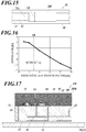
- FIG. 16 is a graph showing a relationship between the wiring width of an antenna conductor and the antenna gain.
- An RFID tag 1L of the eighth embodiment has the same structure as that of the first embodiment or the second embodiment, and also has a structure in which the wiring width LA of a mounting portion where an RFID tag device 20L is mounted of the antenna conductor 12 in the short side direction is smaller than the width LB of the second surface conductor 32 in the same direction.
- a simulation in which the wiring width LA of the mounting portion of the antenna conductor 12 was changed was carried out to calculate the antenna gain in the z direction.
- the obtained simulation result is shown in FIG. 16 .
- This simulation result shows that as the wiring width LA is smaller than the width LB of the second surface conductor 32, the antenna gain is higher.
- This change in the antenna gain was caused by the following; when the wiring width LA is smaller, radio waves that travel from the RFID tag device 20L to the opposite surface of the antenna conductor 12 via the both edges of the antenna conductor 12 in the short side direction increase.
- the wiring width LA of the antenna conductor 12 smaller than the width LB of the second surface conductor 32 enhances the degree of coupling between the RFID tag device 20L and the antenna conductor 12 and can further extend the wireless available distance.
- FIG. 17 is a vertical sectional view showing an RFID tag according to a ninth embodiment.
- An RFID tag 1M of the ninth embodiment has any one of the structures of the first to eighth embodiments, and also has a structure in which a sensor 55 that detects a predetermined physical quantity is mounted in an RFID tag device 20M.
- a sensor 55 there are various applicable sensors, examples of which include a temperature sensor, an acceleration sensor and a pressure sensor.
- the sensor 55 may be connected to the RFID tag IC 50 so as to output detection values thereto, and the detection values by the sensor 55 may be stored, of the RFID tag IC 50, in a memory from which data is readable by an external reader/writer.
- an effect of reading a predetermined physical quantity of the surrounding environment with an external reader/writer can be obtained.
- the present invention is not limited to the above embodiments.
- a structure in which any two or more of combinable features among the features of the first to ninth embodiments are combined may be employed.
- a type of RFID tag device having one side filled with the molded resin 60 is used, but as the RFID tag devices 20E to 201, 20L and 20M of the first to fifth, eighth and ninth embodiments, a type of RFID tag device having a cavity structure may be used.
- the RFID tags 1 and 1E to 1M are configured to operate by receiving electric power from a reader/writer, but may have a built-in cell/battery and perform wireless communications by electric power of the cell/battery. Further, the details described in the embodiments can be appropriately modified within a range not departing from the scope of the invention.
- FIG. 18A shows an RFID tag according to a tenth embodiment.
- FIG. 18B is an enlarged view of an area C1 shown in FIG. 18A .
- FIG. 18A shows, as a representative configuration example, an example in which the RFID tag device 20G shown in FIG. 10A is employed.
- any one of the RFID tag devices 20A to 20K and 20M shown in FIG. 2 to FIG. 10A , FIG. 11A , FIG. 12A , FIG. 13A , FIG. 14A and FIG. 17 , or a configuration accompanied with any one of the modifications described in the above embodiments may be employed.
- the position P10 of a node of a resonant radio wave voltage Vr on the antenna conductor 12 is located opposite the short-circuit conductor(s) 41 across the center O1 of the second surface conductor 32.
- the direction Z is a direction in which the antenna conductor 12 and the second surface conductor 32 face one another.
- the position P10 of the node corresponds to the center point of the antenna conductor 12 in the long side direction when the antenna conductor 12 is a dipole antenna.
- the antenna conductor is not limited to having a long straight shape, and may be shaped into a long meandering path.
- the center point of the antenna conductor corresponds to the position of the center in the distance along the meandering path.
- an antenna conductor 12M may be a monopole antenna.
- the position P10 of the node corresponds to a grounding point.
- the position P10 of the node of the antenna conductor 12 may be located in an area W1 with an end t1 of the second surface conductor 32 as the center ( FIG. 18B ).
- the end t1 is an end of the second surface conductor 32 opposite the short-circuit conductor(s) 41, and the length of the area W1 corresponds to one-fourth of the length L1 of the second surface conductor 32 in the long side direction.
- the position P10 of the node of the antenna conductor 12 may be located in an area W2 from the end t1 of the second surface conductor 32 opposite the short-circuit conductor(s) 41 to an end t2 of the capacitance sheet conductor 33 opposite the short-circuit conductor(s) 41 ( FIG. 18B ).
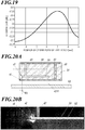
- FIG. 19 is a graph showing a relationship between the position of the RFID tag device and the antenna gain. This graph shows the antenna gain obtained by a simulation in which the position of the RFID tag device 20G was shifted. As shown in FIG. 19 , when the center point of the RFID tag device 20G is shifted to one side across the position P10 of the node of the antenna conductor 12, high antenna gain is obtained. In the simulation, the calculation was carried out about the RFID tag device 20G having 5 mm as a dimension in the long side direction, and 2 mm or around at which the local maximum point of the antenna gain appears indicates that the end of the RFID tag device 20G opposite the short-circuit conductor(s) 41 is arranged at or around the position P10 of the node.
- FIG. 20A , FIG. 21A and FIG. 22A show three reference examples of RFID tag devices.
- FIG. 20B , FIG. 21B and FIG. 22B show the field intensity at the end opposite the short-circuit conductor(s) in the respective RFID tag devices of the three reference examples.
- FIG. 20A , FIG. 21A and FIG. 22A each show a positional relationship between predetermined conductors of the RFID tag device, wherein the RFID tag IC 50 and the connection conductors 43, 44 are omitted.
- FIG. 20B , FIG. 21B and FIG. 22B show simulation results of the field intensity in an area C1 shown in FIG. 20A , FIG. 21A and FIG. 22A , respectively, wherein lighter portions represent higher field intensities.
- the RFID tag devices of three forms shown in FIG. 20A , FIG. 21B and FIG. 22B are different from one another in distance (the length of the area W2) between the end t1 of the second surface conductor 32 (the end t1 opposite the short-circuit conductor(s) 41) and the end t2 of the capacitance sheet conductor 33 (the end t2 opposite to the short-circuit conductor (s) 41).
- the end t1 of the second surface conductor 32 the end t1 opposite the short-circuit conductor(s) 41
- the end t2 of the capacitance sheet conductor 33 the end t2 opposite to the short-circuit conductor (s) 41).
- FIG. 20B , FIG. 21B and FIG. 22B in the configuration having the capacitance sheet conductor 33, a strong electric field is generated between the capacitance sheet conductor 33 and the second surface conductor 32.
- the strong electric field is output from the opening between the end t1 of the second surface conductor 32 and the end t2 of the capacitance sheet conductor 33.
- FIG. 20B , FIG. 21B and FIG. 22B on the antenna conductor 12 side too, in the area W2 between the end t1 of the second surface conductor 32 and the end t2 of the capacitance sheet conductor 33, the strong electric field is output.
- the position P10 of the node of the antenna conductor 12 adjusted to the opposite side to the short-circuit conductor(s) 41 can achieve high antenna gain. Further, the position P10 of the node of the antenna conductors 12 adjusted to the area W1 or the area W2 shown in FIG. 18B can achieve higher antenna gain. As shown in FIG. 23 , even when a monopole antenna is employed, an RFID tag device arranged in the same manner as the above with respect to the position P10 of the node of the antenna conductor 12M can achieve high antenna gain.
- the RFID tag device has the capacitance sheet conductor, but even when it does not have the capacitance sheet conductor, a strong electric field is output from the gap between the first surface conductor and the second surface conductor on the opposite side to the short-circuit conductor(s) 41.
- the configuration in which the position of the node of the antenna conductor is adjusted to the opposite side to the short-circuit conductor(s) or the configuration in which the position of the node of the antenna conductor is adjusted to the area W1 can achieve high antenna gain.
- the details described in the embodiment can be appropriately modified within a range not departing from the scope of the invention.
- the present disclosure is applicable to an RFID tag.
Abstract
Description
- The present disclosure relates to an RFID (Radio Frequency Identifier) tag.
- There has been an RFID tag configured by mounting an RFID tag IC (Integrated Circuit) on a seat antenna. In
WO 2009/142114 A1 , there is disclosed an RFID tag in which an RFID tag IC is mounted on an antenna (radiation plate) via a power supply circuit board having a power supply circuit. - An RFID tag according to the present disclosure includes:
- an RFID tag device including an RFID tag IC and a board where the RFID tag IC is mounted; and
- a seat antenna to which the RFID tag device is fixed, the seat antenna including an antenna conductor,
- wherein the board includes:
- a first surface conductor;
- a second surface conductor disposed between the first surface conductor and the antenna conductor; and
- a short-circuit conductor short-circuiting the first surface conductor and the second surface conductor, and
- wherein a direction from a connection part in the second surface conductor with the short-circuit conductor to a center of the second surface conductor is aligned with a long side direction of the antenna conductor.
- An RFID tag of another aspect according to the present disclosure includes:
- an RFID tag device including an RFID tag IC and a board where the RFID tag IC is mounted; and
- an antenna conductor,
- wherein the board includes:
- a first surface conductor disposed opposite the antenna conductor;
- a second surface conductor that faces the antenna conductor; and
- a short-circuit conductor that short-circuits the first surface conductor and the second surface conductor, and
- wherein when the RFID tag is viewed in a direction in which the second surface conductor and the antenna conductor face one another, a position of a node of a resonant radio wave voltage on the antenna conductor is located opposite the short-circuit conductor across a center of the second surface conductor.
- According to the present disclosure, an effect of extending a communicable distance by simple and highly reliable antenna connection can be obtained.
-
-
FIG. 1A is a perspective view showing a first example of an RFID tag of embodiments according to the present disclosure. -
FIG. 1B is a perspective view showing a second example of the RFID tag of the embodiments according to the present disclosure. -
FIG. 2 is a vertical sectional view showing a first example of a representative RFID tag device. -
FIG. 3 is an exploded perspective view of the RFID tag device shown inFIG. 2 . -
FIG. 4 is a vertical sectional view showing a second example of a representative RFID tag device. -
FIG. 5 is a vertical sectional view showing a third example of a representative RFID tag device. -
FIG. 6 is an exploded perspective view of the RFID tag device shown inFIG. 5 . -
FIG. 7 is a vertical sectional view showing a fourth example of a representative RFID tag device. -
FIG. 8 is a bottom view of an RFID tag device included in an RFID tag according to a first embodiment. -
FIG. 9 is a bottom view of an RFID tag device included in an RFID tag according to a second embodiment. -
FIG. 10A is a vertical sectional view showing an RFID tag according to a third embodiment. -
FIG. 10B is a vertical sectional view showing a comparative example against the RFID tag according to the third embodiment. -
FIG. 11A is a vertical sectional view showing an RFID tag according to a fourth embodiment. -
FIG. 11B is a vertical sectional view showing a comparative example against the RFID tag according to the fourth embodiment. -
FIG. 12A is a vertical sectional view showing an RFID tag according to a fifth embodiment. -
FIG. 12B is a vertical sectional view showing a comparative example against the RFID tag according to the fifth embodiment. -
FIG. 13A is a vertical sectional view showing an RFID tag according to a sixth embodiment. -
FIG. 13B is a vertical sectional view showing a comparative example against the RFID tag according to the sixth embodiment. -
FIG. 14A is a vertical sectional view showing an RFID tag according to a seventh embodiment. -
FIG. 14B is a vertical sectional view showing a comparative example against the RFID tag according to the seventh embodiment. -
FIG. 15 is a plan view showing an RFID tag according to an eighth embodiment. -
FIG. 16 is a graph showing a relationship between the wiring width of an antenna conductor and antenna gain. -
FIG. 17 is a vertical sectional view showing an RFID tag according to a ninth embodiment. -
FIG. 18A shows an RFID tag according to a tenth embodiment. -
FIG. 18B is an enlarged view of an area C1 shown inFIG 18A . -
FIG. 19 is a graph showing a relationship between the position of the RFID tag device and the antenna gain. -
FIG. 20A shows a first reference example of an RFID tag device. -
FIG. 20B shows field intensity at an end opposite a short-circuit conductor in the RFID tag device of the first reference example. -
FIG. 21A shows a second reference example of an RFID tag device. -
FIG. 21B shows the field intensity at the end opposite the short-circuit conductor in the RFID tag device of the second reference example. -
FIG. 22A shows a third reference example of an RFID tag device. -
FIG. 22B shows the field intensity at the end opposite the short-circuit conductor in the RFID tag device of the third reference example. -
FIG. 23 shows an RFID tag according to an eleventh embodiment. - Hereinafter, embodiments according to the present disclosure will be described in detail with reference to the drawings.
-
FIG. 1A is a perspective view showing a first example of an RFID tag of embodiments according to the present disclosure.FIG. 1B is a perspective view showing a second example of the RFID tag of the embodiments according to the present disclosure. - As shown in
FIG. 1A , an RFID tag 1 of the embodiments includes aseat antenna 10 and anRFID tag device 20. Thesheet antenna 10 includes asheet 11 and a film-shapedantenna conductor 12 located on thesheet 11. Theantenna conductor 12 is film-shaped and long along one side. As shown inFIG. 1B , theantenna conductor 12 may be meandering. The length of theantenna conductor 12 in a long side direction may be adjusted to a half wavelength of a radio signal(s), or to a length different therefrom. - The
RFID tag device 20 is configured by mounting an RFID tag IC 50 (FIG. 2 to FIG. 7 ) on a board, and performs wireless communications with a reader/writer by receiving electric power from the reader/writer via radio waves. Although not particularly limited, theRFID tag device 20 performs wireless communications by using radio waves of UHF (Ultra High Frequency) band. - As the
RFID tag device 20, there are various applicable forms that are different from one another in shape of an insulating substrate, in patterns and positions of conductors on and in the insulating substrate, for example. Representative four types of these will be described. In the following description, directions may be expressed by using the orthogonal coordinate system xyz fixedly defined forRFID tag devices 20A to 20D. Each of theRFID tag devices 20A to 20D excluding theRFID tag IC 50 corresponds to an example of the board according to the present invention. -
FIG. 2 is a vertical sectional view showing a first example of a representative RFID tag device.FIG. 3 is an exploded perspective view of the RFID tag device shown inFIG. 2 . InFIG. 3 , a short-circuit conductor 41, acapacitance connection conductor 42 andconnection conductors - An
RFID tag device 20A of the first example includes: an insulatingsubstrate 21 having a first surface and a second surface on the opposite side and extending in the x and y directions; afirst surface conductor 31 disposed on the first surface of the insulatingsubstrate 21; asecond surface conductor 32 disposed on the second surface of the insulatingsubstrate 21; and acapacitance sheet conductor 33 located inside the insulatingsubstrate 21. Thecapacitance sheet conductor 33 is a sheet conductor extending in the x and y directions as with thefirst surface conductor 31 and thesecond surface conductor 32. Thefirst surface conductor 31 has a throughhole 31a. In the throughhole 31a, twoelectrode pads RFID tag IC 50 are disposed. On the first surface of the insulatingsubstrate 21, theRFID tag IC 50 is mounted, and its two terminals are connected to theelectrode pads substrate 21, a moldedresin 60 is disposed, and thefirst surface conductor 31 and theRFID tag IC 50 are embedded in the moldedresin 60. - The
RFID tag device 20A further includes the short-circuit conductor 41, thecapacitance connection conductor 42 and theconnection conductors substrate 21 and each extending in the z direction. The short-circuit conductor 41 is connected to thefirst surface conductor 31 and thesecond surface conductor 32 to short-circuit these. Thecapacitance connection conductor 42 is connected to thefirst surface conductor 31 and thecapacitance sheet conductor 33 to electrically connect these. Theconnection conductor 43 electrically connects theelectrode pad 34 and thecapacitance sheet conductor 33. Theconnection conductor 44 electrically connects theelectrode pad 35 and thesecond surface conductor 32. Theconnection conductor 44 passes through a throughhole 33a of thecapacitance sheet conductor 33, and does not contact thecapacitance sheet conductor 33. - The insulating
substrate 21 is, for example, a dielectric, such as an aluminum oxide sintered body, an aluminum nitride sintered body, a mullite sintered body or a glass-ceramic sintered body, and can be formed, for example, by stacking ceramic green sheets, which are sheet-shaped layers, on top of one another and firing these. - The
first surface conductor 31, thesecond surface conductor 32 and theelectrode pads substrate 21 before firing) by using a method, such as screen printing, and thereafter firing the metal paste together with the ceramic green sheets. Thecapacitance sheet conductor 33 can be formed by printing the metal paste at its position on a ceramic green sheet therefor at a stage where the ceramic green sheets, which are the insulatingsubstrate 21 before firing, are separate layers by using a method, such as screen printing, and thereafter stacking the layers of the ceramic green sheets on top of one another and firing all together. As the metal paste, for example, a material in which copper powder is mixed with an organic solvent and an organic binder can be used. The surfaces of the conductors, such as thefirst surface conductor 31, thesecond surface conductor 32 and theelectrode pads substrate 21 may be coated with a plating layer(s) of nickel, cobalt, palladium, gold or the like in order to suppress oxidation corrosion and enhance coupling/joining characteristics of wire bonding. - The short-
circuit conductor 41, thecapacitance connection conductor 42 and theconnection conductors substrate 21 before firing, filing these with metal paste, and firing the metal paste together with the ceramic green sheets. As the metal paste, for example, a material in which copper powder is mixed with an organic solvent and an organic binder can be used. - According to this configuration, the
first surface conductor 31, thesecond surface conductor 32 and the short-circuit conductor 41 constitute a plate-like inverted-F antenna. TheRFID tag IC 50 can transmit and receive radio signals via the plate-like inverted-F antenna. Thecapacitance sheet conductor 33 faces thesecond surface conductor 32 to constitute a capacitance. This capacitance makes it possible to downsize theRFID tag device 20A while maintaining characteristics of the plate-like inverted-F antenna. -
FIG. 4 is a vertical sectional view showing a second example of a representative RFID tag device. - An
RFID tag device 20B of the second example is configured by excluding thecapacitance sheet conductor 33 from the configuration of the first example. Since thecapacitance sheet conductor 33 is not provided, one of the terminals of theRFID tag IC 50 is connected to thefirst surface conductor 31 via a bonding wire or the like. Theelectrode pad 35 to which the other of the terminals of theRFID tag IC 50 is connected is electrically connected to thesecond surface conductor 32 via theconnection conductor 44. The insulatingsubstrate 21 and the conductors can be manufactured by the same methods as those described in the first example. - According to this configuration, the
first surface conductor 31, thesecond surface conductor 32 and the short-circuit conductor 41 constitute the plate-like inverted-F antenna. TheRFID tag IC 50 can transmit and receive radio signals via the plate-like inverted-F antenna. -
FIG. 5 is a vertical sectional view showing a third example of a representative RFID tag device.FIG. 6 is an exploded perspective view of the RFID tag device shown inFIG. 5 . InFIG. 6 , short-circuit conductors 41a to 41c, thecapacitance connection conductor 42 andconnection conductors - An
RFID tag device 20C of the third example includes: an insulatingsubstrate 21C having a cavity structure (recess 21d); afirst surface conductor 31C disposed on the first surface of the insulatingsubstrate 21C; thesecond surface conductor 32 disposed on the second surface of the insulatingsubstrate 21C; and thecapacitance sheet conductor 33 located inside the insulatingsubstrate 21C. Thefirst surface conductor 31C, thecapacitance sheet conductor 33 and thesecond surface conductor 32 each extend in the x and y directions. Thefirst surface conductor 31C is located in an area excluding the opening of therecess 21d. On the inner bottom surface of therecess 21d, twoelectrode pads RFID tag IC 50 are disposed. Theelectrode pads substrate 21C. TheRFID tag IC 50 is housed in therecess 21d, and its two terminals are connected to theelectrode pads recess 21d may be filled with resin mold. - The
RFID tag device 20C further includes the short-circuit conductors capacitance connection conductor 42 and theconnection conductors substrate 21 and each extending in the z direction. The short-circuit conductors first surface conductor 31C and thesecond surface conductor 32 to short-circuit these. Thecapacitance connection conductor 42 is connected to thefirst surface conductor 31 and thecapacitance sheet conductor 33 to electrically connect these. Theconnection conductor 43C electrically connects theelectrode pad 34 and thesecond surface conductor 32. Theconnection conductor 44C electrically connects theelectrode pad 35C and thecapacitance sheet conductor 33. Theconnection conductor 43C passes through the throughhole 33a of thecapacitance sheet conductor 33, and does not contact thecapacitance sheet conductor 33. - The insulating
substrate 21C and the conductors can be manufactured by the same methods as those described in the first example. - According to this configuration, the
first surface conductor 31C, thesecond surface conductor 32 and the short-circuit conductors RFID tag IC 50 connected thereto can transmit and receive radio signals via the plate-like inverted-F antenna. Thecapacitance sheet conductor 33 faces thesecond surface conductor 32 to constitute the capacitance. This capacitance makes it possible to downsize theRFID tag device 20C while maintaining characteristics of the plate-like inverted-F antenna. -
FIG. 7 is a vertical sectional view showing a fourth example of a representative RFID tag device. - An
RFID tag device 20D of the fourth example is configured by excluding thecapacitance sheet conductor 33 from the configuration of the third example. Since thecapacitance sheet conductor 33 is not provided, one of the terminals of theRFID tag IC 50 is electrically connected to thefirst surface conductor 31C via theelectrode pad 35C and aconnection conductor 45C. The insulatingsubstrate 21 and the conductors can be manufactured by the same methods as those described in the first example. - According to this configuration, the
first surface conductor 31C, thesecond surface conductor 32 and the short-circuit conductor(s) 41 constitute the plate-like inverted-F antenna. TheRFID tag IC 50 connected thereto can transmit and receive radio signals via the plate-like inverted-F antenna. - In the above, four representative examples of the
RFID tag device 20 are described. However, theRFID tag device 20 is not limited to the above examples, and has design freedom in some aspects, examples of which include: the position(s) of the short-circuit conductor(s) 41 or 41a to 41c in the x and y directions and the number thereof; the position(s) of the capacitance connection conductor(s) 42 in the x and y directions and the number thereof; the arrangement order of theelectrode pads 34/34C and 35/35C in the x direction; the position of thecapacitance sheet conductor 33 in the z direction; and the connection destination of thecapacitance connection conductor 42, either thefirst surface conductor 31/31C or thesecond surface conductor 32. The connection destination of thecapacitance connection conductor 42 being thefirst surface conductor 31/31C means that the combination of thecapacitance sheet conductor 33 and thesecond surface conductor 32 constitutes the capacitance. The connection destination of thecapacitance connection conductor 42 being thesecond surface conductor 32 means that the combination of thecapacitance sheet conductor 33 and thefirst surface conductor 31/31C constitutes the capacitance. - Next, RFID tags 1E to 1M of first to ninth embodiments configured by combining, with the
sheet antenna 10, their respectiveRFID tag devices 20E to 20M in each of which one or more of the above-described aspects having design freedom are specified will be described. -
FIG. 8 is a bottom view of an RFID tag device included in an RFID tag according to a first embodiment. - In an
RFID tag 1E of the first embodiment, a first direction X1 of anRFID tag device 20E is aligned with a long side direction X0 (FIG. 1A, FIG. 1B ) of theantenna conductor 12 of theseat antenna 10. TheRFID tag device 20E is fixed on thesheet antenna 10 such that thefirst surface conductor 31 or thesecond surface conductor 32 faces theantenna conductor 12. TheRFID tag device 20E may be fixed on thesheet antenna 10 such that thefirst surface conductor 31 or thesecond surface conductor 32 is electrically connected to theantenna conductor 12, or is non-electrically connected thereto via (with) an adhesive or the like. Thus, theRFID tag device 20E can be fixed on thesheet antenna 10 in a simple manner, and also their electrical connection is unneeded, so that the reliability of coupling between theRFID tag device 20E and theantenna conductor 12 increases. - The first direction X1 of the
RFID tag device 20E is, as shown inFIG. 8 , a direction from a connection part(s) in thesecond surface conductor 32 with the short-circuit conductor (s) 41a, 41b, 41c to the center P0 of thesecond surface conductor 32. When a plurality of connection parts with the short-circuit conductors 41a to 41c is provided, the first direction X1 means a direction obtained by averaging directions from the connection parts with the respective short-circuit conductors 41a to 41c to the center P0. The first direction X1 thus defined corresponds to a radiation direction of radio signals when theRFID tag device 20E alone is viewed. The long side direction X0 of theantenna conductor 12 means the long side direction of an area of a portion and its periphery facing theRFID tag device 20E. - In this description/specification, that a direction A1 of a first element is aligned with a direction A2 of a second element not only means that the directions A1, A2 perfectly coincide with one another, but also means that a direction A2 component in the direction A1 is larger than an orthogonal component to the direction A2 in the direction A1. Hence, that the first direction X1 of the
RFID tag device 20E is aligned with the long side direction X0 of theantenna conductor 12 not only means that these directions perfectly coincide with one another, but also means that a long side direction X0 component in the first direction X1 is larger than a component in a direction perpendicular to the long side direction X0 in the first direction X1. The first direction X1 may be as follows; the first direction X1 ± 30° includes the long side direction X0. The first direction X1 may be as follows; the first direction X1 ± 15° includes the long side direction X0. - A simulation was carried out to calculate antenna gain in the z direction about the first embodiment in which the first direction X1 coincided with the long side direction X0, a form in which the first direction X1 was perpendicular to the long side direction X0, and the
RFID tag device 20E alone. The obtained result is shown in COMPARISON TABLE 1.[TABLE 1] [COMPARISON TABLE 1] RFID TAG WITH SHEET ANTENNA STRUCTURE DEVICE ALONE X1 COINCIDES WITH X0 X1 IS PERPENDICULAR TO X0 ANTENNA GAIN -35 dBi -11.1 dBi -30.5 dBi - The result shown in COMPARISON TABLE 1 indicates that, according to the first embodiment, a relationship between the first direction X1 of the
RFID tag device 20E and the long side direction X0 of theantenna conductor 12 enhances the degree of coupling between the plate-like inverted-F antenna of theRFID tag device 20E and theantenna conductor 12 and extends a communicable distance. -
FIG. 9 is a bottom view of an RFID tag device included in an RFID tag according to a second embodiment. - In an RFID tag 1F of the second embodiment, as shown in
FIG. 9 , a second direction X2 of anRFID tag device 20F is aligned with the long side direction X0 (FIG. 1A, FIG. 1B ) of theantenna conductor 12 of theseat antenna 10. TheRFID tag device 20F is fixed on thesheet antenna 10 such that thefirst surface conductor 31 or thesecond surface conductor 32 faces theantenna conductor 12. TheRFID tag device 20F may be fixed on thesheet antenna 10 such that thefirst surface conductor 31 or thesecond surface conductor 32 is electrically connected to theantenna conductor 12, or is non-electrically connected thereto via (with) an adhesive or the like. Thus, theRFID tag device 20F can be fixed on thesheet antenna 10 in a simple manner, and also their electrical connection is unneeded, so that the reliability of coupling between theRFID tag device 20F and theantenna conductor 12 increases. - The second direction X2 is a direction from the connection parts in the
second surface conductor 32 with the short-circuit conductor(s) 41a, 41b, 41c to a connection part in thesecond surface conductor 32 with thecapacitance connection conductor 42. When a plurality of connection parts with the short-circuit conductors 41a to 41c is provided, or when a plurality of connection parts withcapacitance connection conductors 42 is provided, the second direction X2 is a direction obtained by averaging all directions from the connection parts with the respective short-circuit conductors 41a to 41c to the connection part(s) with the capacitance connection conductor(s) 42. The second direction X2 thus defined corresponds to the radiation direction of radio signals when theRFID tag device 20 alone is viewed. - According to this configuration too, the radiation direction of radio signals of the
RFID tag device 20F aligned with the long side direction of theantenna conductor 12 enhances the degree of coupling between the plate-like inverted-F antenna of theRFID tag device 20F and theantenna conductor 12 and can extend the communicable distance. -
FIG. 10A is a vertical sectional view showing an RFID tag according to a third embodiment.FIG. 10B is a vertical sectional view showing a comparative example against the RFID tag according to the third embodiment. In the example shown inFIG. 10A , thecapacitance sheet conductor 33 and thesecond surface conductor 32 constitute the capacitance, and accordingly thefirst electrode pad 34 is connected to thecapacitance sheet conductor 33 via theconnection conductor 43. - An
RFID tag 1G of the third embodiment has the same structure as that of the second embodiment, and also has a structure in which theelectrode pads RFID tag device 20G are arranged as shown inFIG. 10A in relation to the short-circuit conductor(s) 41 and thecapacitance connection conductor 42. One of the electrode pads, 35, is connected to thesecond surface conductor 32 via theconnection conductor 44, thereby being distinguished from the other of the electrode pads, 34. Hereinafter, in order to distinguish these two from one another, they may be called thefirst electrode pad 34 and thesecond electrode pad 35. - This arrangement of the
electrode pads first electrode pad 34 and the short-circuit conductor(s) 41 is shorter than the distance between thesecond electrode pad 35 and the short-circuit conductor(s) 41. The arrangement also indicates that the distance between thefirst electrode pad 34 and thecapacitance connection conductor 42 is longer than the distance between thesecond electrode pad 35 and thecapacitance connection conductor 42. - A simulation was carried out to calculate the antenna gain in the z direction about the third embodiment (
FIG. 10A ) and the comparative example (FIG. 10B ) in which the arrangement (positions) of theelectrode pads [TABLE 2] [COMPARISON TABLE 2] STRUCTURE ARRANGEMENT OF FIRST ELECTRODE PAD AND SECOND ELECTRODE PAD ARRANGEMENT SHOWN IN FIG. 10A ARRANGEMENT SHOWN IN FIG. 10B ANTENNA GAIN -7.3 dBi -11.1 dBi - Difference in the arrangement of the
electrode pads first electrode pad 34 and thesecond electrode pad 35 connected to theRFID tag IC 50 becomes large. Hence, in the structure shown inFIG. 10A , a strong electric field is generated between thesecond surface conductor 32 and thecapacitance sheet conductor 33, and strong radio waves radiate from the gap between these two. Radio waves radiate more, of the gap between thesecond surface conductor 32 and thecapacitance sheet conductor 33, from an end R1 near the outer periphery of theRFID tag device 20G. When attention is paid to thesecond surface conductor 32, on thesecond surface conductor 32, potential is stable near theconnection conductor 44, one end of which is connected to thesecond electrode pad 35. In the drawings, charges having a high degree of stability are represented by solid lines, and charges having a low degree of stability are represented by broken lines. As compared with the comparative example, in which thesecond electrode pad 35 is far from the end R1, the third embodiment, in which thesecond electrode pad 35 is close to the end R1, stabilizes potential of thesecond surface conductor 32 near the end R1. Thus, as compared with the comparative example, the third embodiment enhances the intensity of radio waves that radiate from the end R1 and enhances the degree of coupling with theantenna conductor 12. - When the
RFID tag device 20G shown inFIG. 10A is compared with the comparative example shown inFIG. 10B , since the arrangement of theelectrode pads capacitance sheet conductor 33 with theconnection conductor 43 to a connection position on thecapacitance sheet conductor 33 with thecapacitance connection conductor 42. During operation of the antenna, current mainly flows, of the capacitance (thesecond surface conductor 32 and the capacitance sheet conductor 33), in the section M1/M2, which is from the connection position with the connection conductor 43 (feed line) to the connection position with thecapacitance connection conductor 42. Positive charges and negative charges shown inFIG. 10A and FIG. 10B reverse their polarities in a period depending on the phase of radio signals that are transmitted or received. Hence, of the capacitance (thesecond surface conductor 32 and the capacitance sheet conductor 33), charges accumulate in the section M1/M2. As the section M1/M2 is longer, more charges accumulate. Accumulation of more charges stabilizes potential difference between thesecond surface conductor 32 and thecapacitance sheet conductor 33 of the capacitance. Hence, as compared with the comparative example shown inFIG. 10B having the short section M2, theRFID tag device 20G having the long section M1 stabilizes the potential difference between thesecond surface conductor 32 and thecapacitance sheet conductor 33 of the capacitance and can radiate radio waves having a higher field intensity. - Thus, according to the
RFID tag 1G of the third embodiment, the degree of coupling between theRFID tag device 20G and theantenna conductor 12 is further enhanced, and the wireless communications distance can be further extended. -
FIG. 11A is a vertical sectional view showing an RFID tag according to a forth embodiment.FIG. 11B is a vertical sectional view showing a comparative example against the RFID tag according to the fourth embodiment. - An
RFID tag 1H of the fourth embodiment has the same structure as that of the second embodiment, and also has a structure in which theelectrode pads RFID tag device 20H are arranged in the same order as that in the third embodiment in relation to the short-circuit conductor(s) 41 and thecapacitance connection conductor 42. - The
RFID tag device 20H of the fourth embodiment is different from that of the third embodiment in that thecapacitance connection conductor 42 is interposed between thecapacitance sheet conductor 33 and thesecond surface conductor 32, and combination of thefirst surface conductor 31 and thecapacitance sheet conductor 33 constitutes the capacitance. In this structure, a strong electric field is generated between thefirst surface conductor 31 and thecapacitance sheet conductor 33, and strong radio waves radiate, of the gap between these two, from an end R2 near the outer periphery of theRFID tag device 20G. - According to this configuration too, the arrangement of the
electrode pads FIG. 11A stabilizes the potential of thesecond surface conductor 32 and thecapacitance sheet conductor 33 in an area near the end R2, from which radio waves radiate, and can enhance the intensity of radio waves that radiate from the end R2. Thus, according to theRFID tag 1H of the fourth embodiment, as with the third embodiment, the degree of coupling between theRFID tag device 20H and theantenna conductor 12 is further enhanced, and the wireless communications distance can be further extended. -
FIG. 12A is a vertical sectional view showing an RFID tag according to a fifth embodiment.FIG. 12B is a vertical sectional view showing a comparative example against the RFID tag according to the fifth embodiment. - An RFID tag 1I of the fifth embodiment has the same structure as that of the second embodiment, and also has a structure in which the
second surface conductor 32 side of the insulatingsubstrate 21 faces thesheet antenna 10, and thecapacitance connection conductor 42 connects thefirst surface conductor 31 and thecapacitance sheet conductor 33. That is, combination of thesecond surface conductor 32 and thecapacitance sheet conductor 33 constitute the capacitance. - In the specific example shown in
FIG. 12A , theelectrode pads electrode pads - A simulation was carried out to calculate the antenna gain in the z direction about the fifth embodiment (
FIG. 12A ) and the comparative example (FIG. 12B ) in which thecapacitance connection conductor 42 was connected to thesecond surface conductor 32. The obtained result is shown in COMPARISON TABLE 3. In the structure shown inFIG. 12B , combination of thefirst surface conductor 31 and thecapacitance sheet conductor 33 constitute the capacitance.[TABLE 3] [COMPARISON TABLE 3] STRUCTURE SURFACE/SHEET CONDUCTORS CONSTITUTING CAPACITANCE CAPACITANCE SHEET CONDUCTOR AND SECOND SURFACE CONDUCTOR ( FIG. 12A )FIRST SURFACE CONDUCTOR AND CAPACITANCE SHEET CONDUCTOR ( FIG. 12B )ANTENNA GAIN -7.3 dBi -8.3 dBi - As described above, radio waves radiate with a high field intensity from a gap between two surface conductors constituting a capacitance to the outside. Hence, as compared with the comparative example shown in
FIG. 12B , the configuration shown inFIG. 12A , in which thesecond surface conductor 32 constitutes a part of the capacitance, radiates radio waves having a high field intensity from the vicinity of theantenna conductor 12. Thus, according to the RFID tag 1I of the fifth embodiment, as compared with the comparative example shown inFIG. 12B , a high degree of coupling between theRFID tag device 201 and theseat antenna 10 is obtained, and the wireless available distance can be further extended. - Further, according to the RFID tag 1I of the fifth embodiment, the
RFID tag device 201 and theantenna conductor 12 are firmly coupled. Hence, even when a difference is generated in the distance between thesecond surface conductor 32 and theantenna conductor 12 by, for example, the thickness of an adhesive, the shift of the resonant peak frequency of the antenna after the coupling can be suppressed. For this reason too, according to the RFID tag 1I of the fifth embodiment, the wireless available distance can be further extended. -
FIG. 13A is a vertical sectional view showing an RFID tag according to a sixth embodiment.FIG. 13B is a vertical sectional view showing a comparative example against the RFID tag according to the sixth embodiment. - An
RFID tag 1J of the sixth embodiment has the same structure as that of the first embodiment or the second embodiment, and also has a structure in which anRFID tag device 20J has a cavity structure, and therecess 21d is disposed opposite theseat antenna 10. In the sixth embodiment, the arrangement order ofelectrode pads FIG. 13A , and may be reversed. - A simulation was carried out to calculate how much the resonant peak frequency of the antenna was shifted when the
RFID tag device 20J was fixed with a gap between theRFID tag device 20J and thesheet antenna 10 changed. The obtained result is shown in COMPARISON TABLE 4. In the simulation, the shift amount of the resonant peak frequency was calculated about the sixth embodiment (FIG. 13A ) and the configuration (FIG. 13B ) in which therecess 21d was disposed on thesheet antenna 10 side. In the comparative example (FIG. 13B ), the surface conductor on therecess 21d side is referred to as asecond surface conductor 32C, and the surface conductor on the opposite side to therecess 21d is referred to as thefirst surface conductor 31. A case where the gap between theRFID tag device 20J and thesheet antenna 10 was 0.3 mm and a case where the gap was 0.05 mm were compared with one another.[TABLE 4] [COMPARISON TABLE 4] STRUCTURE RECESS DISPOSED ON OPPOSITE SIDE TO SHEET ANTENNA RECESS DISPOSED ON SHEET ANTENNA SIDE SHIFT AMOUNT OF RESONANT PEAK FREQUENCY 1 MHz 3 MHz - Difference in the shift amount of the resonant peak frequency was generated for the reasons described hereinafter. In the comparative example, the distance between the
capacitance sheet conductor 33 and a reference plane as a ground potential in the plate-like inverted-F antenna is, at a portion where therecess 21d is not present, the distance between thecapacitance sheet conductor 33 and thesecond surface conductor 32C, but at a portion where therecess 21d is present, the distance between thecapacitance sheet conductor 33 and theantenna conductor 12. Hence, when a difference is present in the gap between theRFID tag device 20J and thesheet antenna 10 due to the thickness of an adhesive or the like, at the portion where therecess 21d is present, the distance between thecapacitance sheet conductor 33 and the reference plane changes, and this appears as the shift of the resonant peak frequency of the antenna. On the other hand, in the sixth embodiment, the distance between thecapacitance sheet conductor 33 and the reference plane as the ground potential in the plate-like inverted-F antenna is the distance between thecapacitance sheet conductor 33 and thesecond surface conductor 32, and does not differ between the portion where therecess 21d is present and the portion where therecess 21d is not present. Hence, even when a difference is present in the gap between theRFID tag device 20J and thesheet antenna 10, the shift of the resonant peak frequency of the antenna is suppressed. The shift of the resonant peak frequency leads to decrease in the intensity of radio signals in wireless communications where the frequency is constant, and hence is a factor in shortening the communicable distance. Thus, according to theRFID tag 1J of the sixth embodiment, since the shift of the resonant peak frequency is small, the intensity of radio signals is stabilized, and reduction of the communicable distance can be suppressed. - In the sixth embodiment, the
capacitance sheet conductor 33 is provided, but even when thecapacitance sheet conductor 33 is not provided, the distance between thefirst surface conductor 31 and the reference plane is unchanged between the portion where therecess 21d is present and the portion where therecess 21d is not present. Hence, as compared with the comparative example, in which therecess 21d is disposed on thesheet antenna 10 side, the intensity of radio signals is stabilized, and reduction of the communicable distance can be suppressed. That is, the same effects as the above are obtained. -
FIG. 14A is a vertical sectional view showing an RFID tag according to a seventh embodiment.FIG. 14B is a vertical sectional view showing a comparative example against the RFID tag according to the seventh embodiment. - An RFID tag 1K of the seventh embodiment has the same structure as that of the first embodiment or the second embodiment, and also has a structure in which an
RFID tag device 20K has the moldedresin 60 on one side, and the moldedresin 60 is disposed opposite thesheet antenna 10. In the seventh embodiment, the arrangement order of theelectrode pads FIG. 14A , and may be reversed. - A simulation was carried out to calculate the antenna gain in the z-direction about the seventh embodiment (
FIG 14A ) and the configuration (FIG 14B ) in which the moldedresin 60 was disposed on thesheet antenna 10 side. The obtained result is shown in COMPARISON TABLE 5.[TABLE 5] [COMPARISON TABLE 5] STRUCTURE MOLDED RESIN DISPOSED ON OPPOSITE SIDE TO SHEET ANTENNA MOLDED RESIN DISPOSED ON SHEET ANTENNA SIDE ANTENNA GAIN -7.3 dBi -10.3 dBi - As described above, radio waves radiate with a high field intensity from a gap between surface conductors (the
first surface conductor 31, thesecond surface conductor 32, the capacitance sheet conductor 33) to the outside. In the comparative example shown inFIG. 14B , due to the interposition of the moldedresin 60, the distance between an end R3 of theRFID tag device 20K from which radio waves radiate and theantenna conductor 12 of thesheet antenna 10 is long, and the degree of coupling between these decreases. On the other hand, in the seventh embodiment shown inFIG. 14A , the end R3 of theRFID tag device 20K from which radio waves radiate is near theantenna conductor 12 of theseat antenna 10, and the degree of coupling between these increases. Thus, according to the RFID tag 1K of the seventh embodiment, a high degree of coupling between theRFID tag device 20K and theseat antenna 10 is obtained, and the wireless available distance can be further extended. -
FIG. 15 is a plan view showing an RFID tag according to an eighth embodiment.FIG. 16 is a graph showing a relationship between the wiring width of an antenna conductor and the antenna gain. - An RFID tag 1L of the eighth embodiment has the same structure as that of the first embodiment or the second embodiment, and also has a structure in which the wiring width LA of a mounting portion where an
RFID tag device 20L is mounted of theantenna conductor 12 in the short side direction is smaller than the width LB of thesecond surface conductor 32 in the same direction. - A simulation in which the wiring width LA of the mounting portion of the
antenna conductor 12 was changed was carried out to calculate the antenna gain in the z direction. The obtained simulation result is shown inFIG. 16 . This simulation result shows that as the wiring width LA is smaller than the width LB of thesecond surface conductor 32, the antenna gain is higher. This change in the antenna gain was caused by the following; when the wiring width LA is smaller, radio waves that travel from theRFID tag device 20L to the opposite surface of theantenna conductor 12 via the both edges of theantenna conductor 12 in the short side direction increase. - As described above, according to the RFID tag 1L of the eighth embodiment, the wiring width LA of the
antenna conductor 12 smaller than the width LB of thesecond surface conductor 32 enhances the degree of coupling between theRFID tag device 20L and theantenna conductor 12 and can further extend the wireless available distance. -
FIG. 17 is a vertical sectional view showing an RFID tag according to a ninth embodiment. - An
RFID tag 1M of the ninth embodiment has any one of the structures of the first to eighth embodiments, and also has a structure in which asensor 55 that detects a predetermined physical quantity is mounted in anRFID tag device 20M. As thesensor 55, there are various applicable sensors, examples of which include a temperature sensor, an acceleration sensor and a pressure sensor. Thesensor 55 may be connected to theRFID tag IC 50 so as to output detection values thereto, and the detection values by thesensor 55 may be stored, of theRFID tag IC 50, in a memory from which data is readable by an external reader/writer. - According to the
RFID tag 1M of the ninth embodiment, an effect of reading a predetermined physical quantity of the surrounding environment with an external reader/writer can be obtained. - In the above, several embodiments are described. However, the present invention is not limited to the above embodiments. For example, a structure in which any two or more of combinable features among the features of the first to ninth embodiments are combined may be employed. Further, in the first to fifth, eighth and ninth embodiments, as the
RFID tag devices 20E to 201, 20L and 20M, a type of RFID tag device having one side filled with the moldedresin 60 is used, but as theRFID tag devices 20E to 201, 20L and 20M of the first to fifth, eighth and ninth embodiments, a type of RFID tag device having a cavity structure may be used. Further, in the above embodiments, the RFID tags 1 and 1E to 1M are configured to operate by receiving electric power from a reader/writer, but may have a built-in cell/battery and perform wireless communications by electric power of the cell/battery. Further, the details described in the embodiments can be appropriately modified within a range not departing from the scope of the invention. -
FIG. 18A shows an RFID tag according to a tenth embodiment.FIG. 18B is an enlarged view of an area C1 shown inFIG. 18A . - In an RFID tag 1N according to the tenth embodiment, the position of the
RFID tag device 20G with respect to theantenna conductor 12 is specified.FIG. 18A shows, as a representative configuration example, an example in which theRFID tag device 20G shown inFIG. 10A is employed. However, as the RFID tag device, any one of theRFID tag devices 20A to 20K and 20M shown inFIG. 2 to FIG. 10A ,FIG. 11A ,FIG. 12A ,FIG. 13A ,FIG. 14A andFIG. 17 , or a configuration accompanied with any one of the modifications described in the above embodiments may be employed. - When the RFID tag 1N of the tenth embodiment is viewed in a direction Z, the position P10 of a node of a resonant radio wave voltage Vr on the
antenna conductor 12 is located opposite the short-circuit conductor(s) 41 across the center O1 of thesecond surface conductor 32. - The direction Z is a direction in which the
antenna conductor 12 and thesecond surface conductor 32 face one another. The position P10 of the node corresponds to the center point of theantenna conductor 12 in the long side direction when theantenna conductor 12 is a dipole antenna. The antenna conductor is not limited to having a long straight shape, and may be shaped into a long meandering path. In this case, the center point of the antenna conductor corresponds to the position of the center in the distance along the meandering path. As shown inFIG. 23 , anantenna conductor 12M may be a monopole antenna. In this case, the position P10 of the node corresponds to a grounding point. - Further, when the RFID tag 1N of the tenth embodiment is viewed in the direction Z, the position P10 of the node of the
antenna conductor 12 may be located in an area W1 with an end t1 of thesecond surface conductor 32 as the center (FIG. 18B ). The end t1 is an end of thesecond surface conductor 32 opposite the short-circuit conductor(s) 41, and the length of the area W1 corresponds to one-fourth of the length L1 of thesecond surface conductor 32 in the long side direction. - Further, when the RFID tag 1N of the tenth embodiment is viewed in the direction Z, the position P10 of the node of the
antenna conductor 12 may be located in an area W2 from the end t1 of thesecond surface conductor 32 opposite the short-circuit conductor(s) 41 to an end t2 of thecapacitance sheet conductor 33 opposite the short-circuit conductor(s) 41 (FIG. 18B ). -
FIG. 19 is a graph showing a relationship between the position of the RFID tag device and the antenna gain. This graph shows the antenna gain obtained by a simulation in which the position of theRFID tag device 20G was shifted. As shown inFIG. 19 , when the center point of theRFID tag device 20G is shifted to one side across the position P10 of the node of theantenna conductor 12, high antenna gain is obtained. In the simulation, the calculation was carried out about theRFID tag device 20G having 5 mm as a dimension in the long side direction, and 2 mm or around at which the local maximum point of the antenna gain appears indicates that the end of theRFID tag device 20G opposite the short-circuit conductor(s) 41 is arranged at or around the position P10 of the node. -
FIG. 20A ,FIG. 21A andFIG. 22A show three reference examples of RFID tag devices.FIG. 20B ,FIG. 21B andFIG. 22B show the field intensity at the end opposite the short-circuit conductor(s) in the respective RFID tag devices of the three reference examples.FIG. 20A ,FIG. 21A andFIG. 22A each show a positional relationship between predetermined conductors of the RFID tag device, wherein theRFID tag IC 50 and theconnection conductors FIG. 20B ,FIG. 21B andFIG. 22B show simulation results of the field intensity in an area C1 shown inFIG. 20A ,FIG. 21A andFIG. 22A , respectively, wherein lighter portions represent higher field intensities. - The RFID tag devices of three forms shown in
FIG. 20A ,FIG. 21B andFIG. 22B are different from one another in distance (the length of the area W2) between the end t1 of the second surface conductor 32 (the end t1 opposite the short-circuit conductor(s) 41) and the end t2 of the capacitance sheet conductor 33 (the end t2 opposite to the short-circuit conductor (s) 41). As shown inFIG. 20B ,FIG. 21B andFIG. 22B , in the configuration having thecapacitance sheet conductor 33, a strong electric field is generated between thecapacitance sheet conductor 33 and thesecond surface conductor 32. The strong electric field is output from the opening between the end t1 of thesecond surface conductor 32 and the end t2 of thecapacitance sheet conductor 33. As shown inFIG. 20B ,FIG. 21B andFIG. 22B , on theantenna conductor 12 side too, in the area W2 between the end t1 of thesecond surface conductor 32 and the end t2 of thecapacitance sheet conductor 33, the strong electric field is output. - As described above, according to the RFID tag 1N of the tenth embodiment, as indicated by the simulation results shown in
FIG. 19, FIG. 20B ,FIG. 21B andFIG. 22B , the position P10 of the node of theantenna conductor 12 adjusted to the opposite side to the short-circuit conductor(s) 41 can achieve high antenna gain. Further, the position P10 of the node of theantenna conductors 12 adjusted to the area W1 or the area W2 shown inFIG. 18B can achieve higher antenna gain. As shown inFIG. 23 , even when a monopole antenna is employed, an RFID tag device arranged in the same manner as the above with respect to the position P10 of the node of theantenna conductor 12M can achieve high antenna gain. - In the above, the tenth embodiment of the present disclosure is described. However, the present invention is not limited to the above embodiment. For example, in the tenth embodiment, the RFID tag device has the capacitance sheet conductor, but even when it does not have the capacitance sheet conductor, a strong electric field is output from the gap between the first surface conductor and the second surface conductor on the opposite side to the short-circuit conductor(s) 41. Hence, employment of the configuration in which the position of the node of the antenna conductor is adjusted to the opposite side to the short-circuit conductor(s) or the configuration in which the position of the node of the antenna conductor is adjusted to the area W1 can achieve high antenna gain. Further, the details described in the embodiment can be appropriately modified within a range not departing from the scope of the invention.
- The present disclosure is applicable to an RFID tag.
Claims (12)
- An RFID tag comprising:an RFID tag device including an RFID tag IC and a board where the RFID tag IC is mounted; anda seat antenna to which the RFID tag device is fixed, the seat antenna including an antenna conductor,wherein the board includes:a first surface conductor;a second surface conductor disposed between the first surface conductor and the antenna conductor; anda short-circuit conductor short-circuiting the first surface conductor and the second surface conductor, andwherein a direction from a connection part in the second surface conductor with the short-circuit conductor to a center of the second surface conductor is aligned with a long side direction of the antenna conductor.
- The RFID tag according to claim 1,wherein the board further includes:a capacitance sheet conductor disposed between the first surface conductor and the second surface conductor; anda capacitance connection conductor electrically connecting the capacitance sheet conductor to the first surface conductor or the second surface conductor, andwherein a direction from the short-circuit conductor to the capacitance connection conductor is aligned with the long side direction of the antenna conductor.
- The RFID tag according to claim 2,wherein the board includes: a first electrode to which a first terminal of the RFID tag IC is connected and that is electrically connected to the first surface conductor or the capacitance sheet conductor; and a second electrode to which a second terminal of the RFID tag IC is connected and that is electrically connected to the second surface conductor, andwherein a distance between the first electrode and the short-circuit conductor is shorter than a distance between the second electrode and the short-circuit conductor, and a distance between the first electrode and the capacitance connection conductor is longer than a distance between the second electrode and the capacitance connection conductor.
- The RFID tag according to claim 2 or 3,wherein the capacitance connection conductor is connected to the first surface conductor and the capacitance sheet conductor, andwherein combination of the second surface conductor and the capacitance sheet conductor constitutes a capacitance.
- The RFID tag according to any one of claims 1 to 4,wherein the board has a recess where the RFID tag IC is housed, andwherein an opening of the recess faces an opposite side to the antenna conductor.
- The RFID tag according to any one of claims 1 to 4,wherein the board includes a molded resin in which the RFID tag IC is embedded, andwherein the molded resin is disposed opposite the antenna conductor.
- The RFID tag according to any one of claims 1 to 6, wherein a width dimension of at least a portion of the antenna conductor in a short side direction is smaller than a width dimension of the second surface conductor in the short side direction, the portion facing the board.
- The RFID tag according to any one of claims 1 to 7, further comprising a sensor that is mounted in the board and detects a predetermined physical quantity.
- An RFID tag comprising:an RFID tag device including an RFID tag IC and a board where the RFID tag IC is mounted; andan antenna conductor,wherein the board includes:a first surface conductor disposed opposite the antenna conductor;a second surface conductor that faces the antenna conductor; anda short-circuit conductor that short-circuits the first surface conductor and the second surface conductor, andwherein when the RFID tag is viewed in a direction in which the second surface conductor and the antenna conductor face one another, a position of a node of a resonant radio wave voltage on the antenna conductor is located opposite the short-circuit conductor across a center of the second surface conductor.
- The RFID tag according to claim 9, wherein the position of the node of the resonant radio wave voltage is a center of the antenna conductor when the antenna conductor is a dipole antenna, and is a grounding point when the antenna conductor is a monopole antenna.
- The RFID tag according to claim 9 or 10, wherein when the RFID tag is viewed in the direction in which the second surface conductor and the antenna conductor face one another, the position of the node of the resonance radio wave voltage on the antenna conductor is located in an area with an end of the second surface conductor opposite the short-circuit conductor as a center, the area having a length that is one-fourth of a length of the second surface conductor in a long side direction.
- The RFID tag according to claim 9 or 10, wherein the board includes a capacitance sheet conductor between the first surface conductor and the second surface conductor, and
wherein when the RFID tag is viewed in the direction in which the second surface conductor and the antenna conductor face one another, the position of the node of the resonant radio wave voltage on the antenna conductor is located in an area from an end of the second surface conductor opposite the short-circuit conductor to an end of the capacitance sheet conductor opposite the short-circuit conductor.
Applications Claiming Priority (3)
| Application Number | Priority Date | Filing Date | Title |
|---|---|---|---|
| JP2018222953 | 2018-11-29 | ||
| JP2019033429 | 2019-02-27 | ||
| PCT/JP2019/045757 WO2020110930A1 (en) | 2018-11-29 | 2019-11-22 | Rfid tag |
Publications (2)
| Publication Number | Publication Date |
|---|---|
| EP3889838A1 true EP3889838A1 (en) | 2021-10-06 |
| EP3889838A4 EP3889838A4 (en) | 2022-12-21 |
Family
ID=70854335
Family Applications (1)
| Application Number | Title | Priority Date | Filing Date |
|---|---|---|---|
| EP19889371.1A Pending EP3889838A4 (en) | 2018-11-29 | 2019-11-22 | Rfid tag |
Country Status (5)
| Country | Link |
|---|---|
| US (1) | US20220121898A1 (en) |
| EP (1) | EP3889838A4 (en) |
| JP (1) | JP7142716B2 (en) |
| CN (1) | CN113015980A (en) |
| WO (1) | WO2020110930A1 (en) |
Families Citing this family (2)
| Publication number | Priority date | Publication date | Assignee | Title |
|---|---|---|---|---|
| US20210330190A1 (en) * | 2020-04-22 | 2021-10-28 | Biotags, LLC | Temperature sensor patch and system |
| JP7383312B2 (en) | 2022-03-07 | 2023-11-20 | 日本ミクロン株式会社 | wireless sensor |
Family Cites Families (9)
| Publication number | Priority date | Publication date | Assignee | Title |
|---|---|---|---|---|
| EP2144328B1 (en) * | 2007-03-30 | 2017-11-01 | Nitta Corporation | Wireless communication improving sheet body, wireless ic tag and wireless communication system using the wireless communication improving sheet body and the wireless ic tag |
| CN103729676B (en) | 2008-05-21 | 2017-04-12 | 株式会社村田制作所 | Wireless ic device |
| TWI511378B (en) * | 2012-04-03 | 2015-12-01 | Ind Tech Res Inst | Multi-band multi-antenna system and communiction device thereof |
| JP6050961B2 (en) * | 2012-06-18 | 2016-12-21 | トッパン・フォームズ株式会社 | Non-contact data transmitter / receiver |
| TWI607601B (en) * | 2015-02-10 | 2017-12-01 | Phoenix Solution Co Ltd | RF tag antenna and its manufacturing method and RF tag |
| CN107864688B (en) * | 2016-07-22 | 2019-12-31 | 京瓷株式会社 | Substrate for RFID tag, and RFID system |
| WO2018074553A1 (en) * | 2016-10-21 | 2018-04-26 | 京セラ株式会社 | Substrate for tags, rfid tag and rfid system |
| DE112018000095T5 (en) * | 2017-02-21 | 2019-05-09 | Murata Manufacturing Co., Ltd. | RFID-LABEL |
| JP7062772B2 (en) * | 2018-08-22 | 2022-05-06 | 京セラ株式会社 | RFID tag boards, RFID tags and RFID systems |
-
2019
- 2019-11-22 US US17/295,073 patent/US20220121898A1/en active Pending
- 2019-11-22 WO PCT/JP2019/045757 patent/WO2020110930A1/en unknown
- 2019-11-22 JP JP2020557661A patent/JP7142716B2/en active Active
- 2019-11-22 CN CN201980075335.0A patent/CN113015980A/en active Pending
- 2019-11-22 EP EP19889371.1A patent/EP3889838A4/en active Pending
Also Published As
| Publication number | Publication date |
|---|---|
| US20220121898A1 (en) | 2022-04-21 |
| CN113015980A (en) | 2021-06-22 |
| JP7142716B2 (en) | 2022-09-27 |
| WO2020110930A1 (en) | 2020-06-04 |
| JPWO2020110930A1 (en) | 2021-09-30 |
| EP3889838A4 (en) | 2022-12-21 |
Similar Documents
| Publication | Publication Date | Title |
|---|---|---|
| US8528829B2 (en) | Wireless communication device and metal article | |
| JP3148168U (en) | Wireless IC device | |
| JP6360264B2 (en) | RFID tag substrate, RFID tag and RFID system | |
| US20090140947A1 (en) | Antenna Device and Radio-Communication System Using the Same | |
| CN102812593A (en) | Dielectric chip antennas | |
| CN108235792B (en) | Substrate for tag, RFID tag, and RFID system | |
| JP4149357B2 (en) | Compound antenna | |
| US8864039B2 (en) | Transponder tagged object and method for manufacturing a transponder tagged object | |
| US10700433B2 (en) | Wireless communication device and article including the same | |
| JP2012253699A (en) | Wireless communication device, its manufacturing method, and metal article with wireless communication device | |
| EP3889838A1 (en) | Rfid tag | |
| JP5093230B2 (en) | Antenna and wireless communication device | |
| KR101165910B1 (en) | Dual patch antenna module | |
| CN102195142A (en) | Planar antenna system | |
| US11783155B2 (en) | RFID tag board, RFID tag, and RFID system | |
| US9524602B2 (en) | Compact antenna structure with a coupling device | |
| US11275983B2 (en) | RFID tags board, RFID tag and RFID system | |
| JP6807809B2 (en) | RFID tag boards, RFID tags and RFID systems | |
| JP6789172B2 (en) | RFID tag boards, RFID tags and RFID systems | |
| CN114303158A (en) | RFID tag | |
| WO2013120384A1 (en) | Electronic tag |
Legal Events
| Date | Code | Title | Description |
|---|---|---|---|
| STAA | Information on the status of an ep patent application or granted ep patent |
Free format text: STATUS: THE INTERNATIONAL PUBLICATION HAS BEEN MADE |
|
| PUAI | Public reference made under article 153(3) epc to a published international application that has entered the european phase |
Free format text: ORIGINAL CODE: 0009012 |
|
| STAA | Information on the status of an ep patent application or granted ep patent |
Free format text: STATUS: REQUEST FOR EXAMINATION WAS MADE |
|
| 17P | Request for examination filed |
Effective date: 20210518 |
|
| AK | Designated contracting states |
Kind code of ref document: A1 Designated state(s): AL AT BE BG CH CY CZ DE DK EE ES FI FR GB GR HR HU IE IS IT LI LT LU LV MC MK MT NL NO PL PT RO RS SE SI SK SM TR |
|
| DAV | Request for validation of the european patent (deleted) | ||
| DAX | Request for extension of the european patent (deleted) | ||
| RIC1 | Information provided on ipc code assigned before grant |
Ipc: H01Q 1/38 20060101ALI20220714BHEP Ipc: H01Q 9/16 20060101ALI20220714BHEP Ipc: H01Q 9/04 20060101ALI20220714BHEP Ipc: H01Q 13/08 20060101ALI20220714BHEP Ipc: G06K 19/07 20060101ALI20220714BHEP Ipc: G06K 19/077 20060101AFI20220714BHEP |
|
| A4 | Supplementary search report drawn up and despatched |
Effective date: 20221122 |
|
| RIC1 | Information provided on ipc code assigned before grant |
Ipc: H01Q 1/38 20060101ALI20221116BHEP Ipc: H01Q 9/16 20060101ALI20221116BHEP Ipc: H01Q 9/04 20060101ALI20221116BHEP Ipc: H01Q 13/08 20060101ALI20221116BHEP Ipc: G06K 19/07 20060101ALI20221116BHEP Ipc: G06K 19/077 20060101AFI20221116BHEP |
|
| P01 | Opt-out of the competence of the unified patent court (upc) registered |
Effective date: 20230505 |
|
| STAA | Information on the status of an ep patent application or granted ep patent |
Free format text: STATUS: EXAMINATION IS IN PROGRESS |