EP3888112B1 - Elektrischer schliesser - Google Patents
Elektrischer schliesser Download PDFInfo
- Publication number
- EP3888112B1 EP3888112B1 EP19828753.4A EP19828753A EP3888112B1 EP 3888112 B1 EP3888112 B1 EP 3888112B1 EP 19828753 A EP19828753 A EP 19828753A EP 3888112 B1 EP3888112 B1 EP 3888112B1
- Authority
- EP
- European Patent Office
- Prior art keywords
- connecting element
- contact elements
- electrically conductive
- conductive material
- contact
- Prior art date
- Legal status (The legal status is an assumption and is not a legal conclusion. Google has not performed a legal analysis and makes no representation as to the accuracy of the status listed.)
- Active
Links
Images


Classifications
-
- H—ELECTRICITY
- H01—ELECTRIC ELEMENTS
- H01H—ELECTRIC SWITCHES; RELAYS; SELECTORS; EMERGENCY PROTECTIVE DEVICES
- H01H1/00—Contacts
- H01H1/12—Contacts characterised by the manner in which co-operating contacts engage
-
- H—ELECTRICITY
- H01—ELECTRIC ELEMENTS
- H01H—ELECTRIC SWITCHES; RELAYS; SELECTORS; EMERGENCY PROTECTIVE DEVICES
- H01H79/00—Protective switches in which excess current causes the closing of contacts, e.g. for short-circuiting the apparatus to be protected
-
- H—ELECTRICITY
- H01—ELECTRIC ELEMENTS
- H01H—ELECTRIC SWITCHES; RELAYS; SELECTORS; EMERGENCY PROTECTIVE DEVICES
- H01H1/00—Contacts
- H01H1/02—Contacts characterised by the material thereof
-
- H—ELECTRICITY
- H01—ELECTRIC ELEMENTS
- H01H—ELECTRIC SWITCHES; RELAYS; SELECTORS; EMERGENCY PROTECTIVE DEVICES
- H01H1/00—Contacts
- H01H1/02—Contacts characterised by the material thereof
- H01H1/04—Co-operating contacts of different material
-
- H—ELECTRICITY
- H01—ELECTRIC ELEMENTS
- H01H—ELECTRIC SWITCHES; RELAYS; SELECTORS; EMERGENCY PROTECTIVE DEVICES
- H01H1/00—Contacts
- H01H1/06—Contacts characterised by the shape or structure of the contact-making surface, e.g. grooved
-
- H—ELECTRICITY
- H01—ELECTRIC ELEMENTS
- H01H—ELECTRIC SWITCHES; RELAYS; SELECTORS; EMERGENCY PROTECTIVE DEVICES
- H01H3/00—Mechanisms for operating contacts
- H01H3/22—Power arrangements internal to the switch for operating the driving mechanism
- H01H3/24—Power arrangements internal to the switch for operating the driving mechanism using pneumatic or hydraulic actuator
-
- H—ELECTRICITY
- H01—ELECTRIC ELEMENTS
- H01H—ELECTRIC SWITCHES; RELAYS; SELECTORS; EMERGENCY PROTECTIVE DEVICES
- H01H37/00—Thermally-actuated switches
- H01H37/74—Switches in which only the opening movement or only the closing movement of a contact is effected by heating or cooling
- H01H37/76—Contact member actuated by melting of fusible material, actuated due to burning of combustible material or due to explosion of explosive material
-
- H—ELECTRICITY
- H01—ELECTRIC ELEMENTS
- H01H—ELECTRIC SWITCHES; RELAYS; SELECTORS; EMERGENCY PROTECTIVE DEVICES
- H01H39/00—Switching devices actuated by an explosion produced within the device and initiated by an electric current
-
- H—ELECTRICITY
- H01—ELECTRIC ELEMENTS
- H01H—ELECTRIC SWITCHES; RELAYS; SELECTORS; EMERGENCY PROTECTIVE DEVICES
- H01H1/00—Contacts
- H01H1/12—Contacts characterised by the manner in which co-operating contacts engage
- H01H1/14—Contacts characterised by the manner in which co-operating contacts engage by abutting
- H01H1/20—Bridging contacts
-
- H—ELECTRICITY
- H01—ELECTRIC ELEMENTS
- H01H—ELECTRIC SWITCHES; RELAYS; SELECTORS; EMERGENCY PROTECTIVE DEVICES
- H01H1/00—Contacts
- H01H1/50—Means for increasing contact pressure, preventing vibration of contacts, holding contacts together after engagement, or biasing contacts to the open position
- H01H2001/508—Means for increasing contact pressure, preventing vibration of contacts, holding contacts together after engagement, or biasing contacts to the open position with mechanical means to prevent return/reverse movement of movable contact once opening or closing cycle has started
-
- H—ELECTRICITY
- H01—ELECTRIC ELEMENTS
- H01H—ELECTRIC SWITCHES; RELAYS; SELECTORS; EMERGENCY PROTECTIVE DEVICES
- H01H3/00—Mechanisms for operating contacts
- H01H3/22—Power arrangements internal to the switch for operating the driving mechanism
- H01H3/28—Power arrangements internal to the switch for operating the driving mechanism using electromagnet
-
- H—ELECTRICITY
- H01—ELECTRIC ELEMENTS
- H01H—ELECTRIC SWITCHES; RELAYS; SELECTORS; EMERGENCY PROTECTIVE DEVICES
- H01H36/00—Switches actuated by change of magnetic field or of electric field, e.g. by change of relative position of magnet and switch, by shielding
-
- H—ELECTRICITY
- H01—ELECTRIC ELEMENTS
- H01H—ELECTRIC SWITCHES; RELAYS; SELECTORS; EMERGENCY PROTECTIVE DEVICES
- H01H39/00—Switching devices actuated by an explosion produced within the device and initiated by an electric current
- H01H39/004—Closing switches
Definitions
- the subject relates to an electrical closer, in particular for a motor vehicle line, in particular a motor vehicle power line, for example a battery line, for example a battery-motor, battery-starter, battery-generator or starter-generator line.
- a motor vehicle power line for example a battery line, for example a battery-motor, battery-starter, battery-generator or starter-generator line.
- a possible safety concept provides for a short-circuit of the live parts with the help of an electrical closer.
- the on-board electrical system behind the short-circuit is de-energized due to the short-circuit caused by the NO contact.
- a short circuit has the advantage that switching under load is not necessary, which always involves the risk of an arc and thus of current flowing further.
- a closer can be designed in such a way that switching back is impossible, so that permanent protection is guaranteed.
- the publication DE 197 46 566 A1 relates to an arc flash protection device.
- the publication CH 389 729 refers to liquid short circuiters for high and extra high voltages.
- the publication WO 2007/014816 A1 relates to a further developed short-circuiting device for use in low and medium voltage systems for the protection of property and people.
- the object on which the object was based was to provide an electrical closer for safety-relevant systems which closes securely and in which downshifting is made more difficult.
- the electrical closer To connect the electrical closer to a circuit, for example to a motor vehicle line or a motor vehicle power line, it has at least a first and a second electrical connection.
- the respective electrical connection can in each case be formed as a connection lug, connection bolt, screw connection, crimp connection, as a round cable or as a flat cable.
- the electrical closer can be housed in a separate housing and the connections can be routed out of the housing.
- the electrical closer has a first contact element, which is electrically connected to the first connection, and a second contact element, which is electrically connected to the second connection.
- the electrical contact elements are isolated from one another and spatially separated.
- the contact elements are preferably arranged inside the housing of the electrical closer.
- a connecting element is provided for contacting the two contact elements with one another.
- the connecting element is formed from an electrically conductive material and can be brought into contact with the two contact elements at the same time, as a result of which a short circuit is formed across the contact elements and thus a closed position of the closer is realized.
- a relative movement in particular a translatory movement, is brought about at least one of the contact elements with respect to the connecting element.
- the connecting element In the open position, the connecting element is spatially separated from at least one of the contact elements and there is no electrical connection between the two contact elements and between at least one of the contact elements and the connecting element.
- none of the contact elements is connected to the connecting element.
- one of the contact elements is connected to the connecting element and the second contact element is electrically insulated therefrom.
- a relative movement between the contact elements and the connecting element is such that the second contact element moves relative to the connecting element.
- the connecting element it is also possible for the connecting element to move relative to at least one of the contact elements.
- connecting element and one or both contact elements are moved towards one another relative to one another, there is mechanical and electrical contact between the contact elements and the connecting element, and the connecting element forms a short circuit between the two contact elements.
- An electrically conductive material which encloses the connecting element, offers good protection against resetting while at the same time being light in weight.
- a material is a porous material. This can be in the form of a powder or a porous foam.
- the material is preferably metallic.
- the material is electrically conductive.
- At least parts of the connecting element and/or the contact elements are formed from an electrically conductive material. At least one of the contact elements can penetrate into the material of the connecting element, as a result of which a short circuit is formed in the closed position.
- the connecting element can also be embedded in the electrically conductive material of the contact elements penetrate, creating a short circuit in the closed position.
- the terms penetrate and immerse can be understood synonymously.
- a porous material is described below at various points.
- the relative movement between at least one of the contact elements and the connecting element dips at least one, preferably both, contact elements into the electrically conductive material of the connecting element, or that the connecting element dips into the electrically conductive material of at least one of the contact elements.
- Dipping can be understood to mean mechanical penetration, in particular in the form of piercing or driving in. Penetration into the electrically conductive material can be favored by a corresponding design of the contact elements or of the connecting element.
- a connection occurs between a penetrating element and a penetrated element.
- a penetrating element may be at least one of the contact elements and the penetrated element is in this case the connection element.
- a penetrating element may be the connection element and the penetrated element is in this case at least one of the contact elements.
- the element that is penetrated can be formed at least in parts from the electrically conductive material.
- the penetrating element be formed with an undercut and/or hook-shaped and/or with a barb which is widened counter to the direction of penetration.
- the penetrating element may be one of the contact elements penetrating the connection element or the connection element penetrating at least one of the contact elements.
- one or both contact elements can be surrounded by the electrically conductive material of the connecting element or the connecting element by the electrically conductive material of at least one of the contact elements.
- an end region of the respectively penetrating element is preferably completely surrounded by the electrically conductive material.
- Both contact elements preferably penetrate into the electrically conductive material of the connecting element. However, if there is already an electrical connection between one of the contact elements and the connecting element in the open position, it is also possible for only one of the contact elements to penetrate the electrically conductive material.
- the connecting element which has penetrated the electrically conductive material is surrounded all around by the respective electrically conductive material of at least one of the contact elements. It is proposed in particular that a respective end area of the connecting element is completely surrounded by the respective electrically conductive material.
- Enclosed circumferentially can be understood to mean that along a circumference the penetrating element is completely surrounded by the electrically conductive material and touches it circumferentially.
- An end region can be an end face and a peripheral surface of the penetrating element pointing away from the end face.
- the penetration depth can be between a few mm and a few cm. The greater the depth of penetration into the electrically conductive material, the greater the contact surface and thus the electrical conductivity or conductance between the connecting element and the contact element.
- the electrically conductive material is a porous metal, in particular an open-pore or closed-pore metal foam, in particular made of an aluminum material or a copper material. If foam or metal foam is mentioned below, this can always also be understood as the porous metal, in which case the foam is to be understood merely as an exemplary embodiment of the porous metal.
- the porous metal has an average pore diameter of between 0.2 mm and 0.4 mm. The smaller the pore diameter, the denser the porous metal and the greater the contact area between the porous material and the penetrating element therein and the element being penetrated.
- the contact element penetrates into the connecting element or vice versa.
- the penetrating element has a spike-shaped geometry, for example cone-shaped. It is proposed that the tips of the contact elements are directed in the direction of the connecting element or that the tips of the ends of the connecting element are directed in the direction of the respective contact element.
- the respective tips are preferably in the form of thorns.
- the penetrating element can be formed in the form of a blade.
- the contact elements be formed in one piece with the terminals.
- the terminals that are driven into the electrically conductive material.
- the connecting element is formed as a conductor bridge and that the connecting element dips into the electrically conductive material of the contact elements as a result of the relative movement. It should be noted here that it can also be sufficient if only one end of a connecting element dips into a contact element and the other end of the connecting element is already connected to the other contact element. This applies to all of the explanations here.
- the electrically conductive material be completely enclosed by a housing.
- an insulating material is arranged on the surface of the electrically conductive material in which at least one of the contact elements or the connecting element is immersed. This isolation prevents unwanted contact, for example due to vibration. Sufficient force is required to penetrate the insulation or the housing. This force is applied by accelerating with the help of the drive. When immersed, accelerated by the drive, the connecting element or the contact elements break through the housing wall.
- the housing is preferably formed from an insulating material, so that unintentional contacts are avoided.
- the electrically conductive material completely encloses the connecting element and/or the contact elements after immersion, thus forming a non-positive connection between the connecting element or the contact elements and the electrically conductive material.
- the drive is electrical, electromechanical, magnetic, pyrotechnic or the like.
- An electromechanical drive can in particular be a spring drive, which can be triggered electrically.
- a magnetic drive can in particular be a relay drive.
- a pyrotechnic drive can use a be realized pyrotechnic squib, which can be triggered by an electrical ignition pulse.
- a porous metal can be produced in different ways, in particular foaming of a blowing agent being used to produce the porous metal. Sintering of a metal powder can also lead to the porous material.
- the blowing agent is introduced into a metal powder and the metal-blowing agent mixture is treated, in particular heated, as a result of which the blowing agent outgasses and foams and thus forms the porosity. It is also possible that a metal-salt mixture is formed in a casting process and the salt is then washed out and the remaining metal matrix forms the porous metal.
- Fig. 1a shows a closer 2 with a first terminal 4a and a second terminal 4b.
- the connections 4a, b can be formed as flat parts or round parts.
- the connections 4a, b can in particular be formed as connection lugs, connection bolts, crimp connections, soldered connections, welded connections or the like.
- connections 4a, b can be bimetallic or formed from a metal.
- the connections 4a, b can be formed from a copper material or an aluminum material.
- Contact elements 6a, 6b can be provided in one piece with the terminals 4a, b or also only in electrical contact with them.
- the contact elements 6a, b can be formed from the same metal or from a different metal than the terminals 4a, b.
- the contact elements 6a, 6b can be metallically coated.
- the contact elements 6a, b can be formed from a copper material or an aluminum material.
- the contact elements 6a, b can be mandrel-shaped at the end and point in the direction of a connecting element 8.
- a connecting element 8 can have a housing 8a and a metal foam 8b arranged in the housing 8a.
- the metal foam 8b is described below as representative of a porous metal, so the following description can also be applied to any other porous metal.
- the housing 8a is formed from an insulating material, in particular plastic, and preferably completely encases the metal foam 8b.
- a drive 10 in the form of a squib can be provided on the side of the connecting element 8 facing away from the contact elements 6a, b.
- An electrical pulse can trigger the drive 10 via ignition wires 12, whereupon gas pressure accelerates the connecting element in the direction of the contact elements 6a, b.
- the connecting element 8 is movably arranged in a channel 14 and can be moved in the channel 14 in particular in the direction of movement 16 .
- the movement of the connecting element 8 in the channel 14 in the direction of movement 16 is triggered by the drive 10.
- an ignition pulse is transmitted via the ignition wire 12 and the drive 10 fires.
- the resulting gas pressure causes the connecting element 8 to move in the direction of movement 16.
- the momentum of the connecting element 8 is sufficiently large for the contact elements 6a, b to pierce the housing 8a and penetrate the metal foam 8b.
- a mechanical and electrical connection is created between the front ends of the contact elements 6a, b and the metal foam 8b.
- a short circuit between the contact elements 6a, b is formed via the metal foam 8b and the closer 2 is in a closed position.
- the connecting element 8 remains in this closed position. Since the tips of the contact elements 6a, b are mechanically completely surrounded by the metal foam 8b, the connecting element 8 holds firmly to the contact elements 6a, b and reset is prevented. Barbs or undercuts (not shown) can also be arranged on the tips of the contact elements 6a, b, which prevent the connecting element 8 from being able to move in the opposite direction 16 .
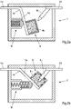
- Figure 2a shows a further exemplary embodiment in which a contact element 6a is mounted pivotably about an axis 6c around the connecting element 4b.
- the contact element 6a is connected to the connecting element 8, in particular the metal foam 8b.
- the connecting element 8 together with the metal foam 8b is in particular arranged captively on the contact element 6a, for example by materially joining the metal foam 8b to a surface of the contact element 6a.
- the drive 10' is formed by a spring which can be triggered electromagnetically, for example.
- the drive 10' When triggered, the drive 10' is triggered via an ignition pulse and the contact element 6a together with the connecting element 8 is accelerated in the direction of the contact element 6b. Through this relative movement, the contact element 6b penetrates, as in figure 2 B shown, in the metal foam 8b and a short circuit between the contact element 6a and the contact element 6b is formed.
- the contact elements 6a, 6b can also be accelerated in a direction of movement 16 in the direction of the connecting element 8, as shown in FIG 3a, b shown.
- the contact elements 6a, b are connected to the connection elements 4a, b in such a way that the contact elements 6a, b are movable in the direction of movement 16.
- a bolt 18 can be provided between the drive 10 and the contact elements 6a, b, which ensures uniform acceleration of the contact elements 6a, b.
- FIG. 3a shows an open position of the closer 2.
- the drive 10 is triggered and the contact elements 6a, b are accelerated in the direction of movement 16 in the direction of the connecting element 8 via the bolt 18.
- the movement impulse is so great that the contact elements 6a, b penetrate the insulating layer 8c and penetrate into the metal foam 8b.
- Figure 3b shows the closed position in which a short circuit is formed between the contact elements 6a, b via the metal foam 8b.
Landscapes
- Chemical & Material Sciences (AREA)
- Engineering & Computer Science (AREA)
- Combustion & Propulsion (AREA)
- Physics & Mathematics (AREA)
- Electromagnetism (AREA)
- Air Bags (AREA)
- Coupling Device And Connection With Printed Circuit (AREA)
- Details Of Connecting Devices For Male And Female Coupling (AREA)
- Fuses (AREA)
Description
- Der Gegenstand betrifft einen elektrischen Schließer, insbesondere für eine Kraftfahrzeugleitung, insbesondere eine Kraftfahrzeugenergieleitung, beispielsweise eine Batterieleitung, beispielsweise eine Batterie-Motor-, Batterie-Starter-, Batterie-Generator- oder Starter-Generator-Leitung.
- In automotiven Anwendungen, jedoch auch in anderen Anwendungen, werden die Sicherheitsanforderungen stets strenger. Gerade bei hohen Strömen ist aus Sicherheitsgründen eine sichere Abschaltung im Fehlerfall notwendig. Nutzer, Insassen und Helfer müssen vor Stromschlägen sicher geschützt werden.
- In Hochvoltanwendungen mit Spannungen von teils über 1000V bei gleichzeitig hohen Strömen, wie sie beispielsweise in automotiven Antriebssträngen auftreten, ist ein zuverlässiges Schalten notwendig, um im Fehler- oder Crashfall einen sicheren Personenschutz zu gewährleisten. Ein mögliches Sicherheitskonzept sieht einen Kurzschluss der spannungsführenden Teile mit Hilfe eines elektrischen Schließers vor. Durch den herbeigeführten Kurzschluss über den Schließer wird das Bordnetz hinter dem Kurzschluss spannungslos geschaltet. Gleichzeitig hat ein Kurzschluss den Vorteil, dass kein Schalten unter Last notwendig ist, bei dem stets die Gefahr eines Lichtbogens und somit eines weiter fließenden Stroms besteht. Außerdem kann ein Schließer so gestaltet werden, dass ein Rückschalten unmöglich wird, so dass eine dauerhafte Sicherung gewährleistet ist.
- Die Veröffentlichung
DE 197 46 566 A1 betrifft eine Störlichtbogen-Schutzvorrichtung. - Die Veröffentlichung
CH 389 729 - Die Veröffentlichung
WO 2007/014816 A1 betrifft eine weiterentwickelte Kurzschließeinrichtung für den Einsatz in Nieder- und Mittelspannungsanlagen zum Sach- und Personenschutz. - Ausgehend von diesem Stand der Technik lag dem Gegenstand die Aufgabe zugrunde, einen elektrischen Schließer für sicherheitsrelevante Systeme zur Verfügung zu stellen, welcher sicher schließt und bei dem eine Rückschaltung erschwert ist.
- Diese Aufgabe wird durch einen elektrischen Schließer nach Anspruch 1 gelöst.
- Zum Anschluss des elektrischen Schließers an eine Schaltung, beispielsweise an eine Kraftfahrzeugleitung oder eine Kraftfahrzeugenergieleitung, verfügt dieser über zumindest einen ersten und einen zweiten elektrischen Anschluss. Der jeweilige elektrische Anschluss kann jeweils als Anschlussfahne, Anschlussbolzen, Schraubanschluss, Crimpanschluss, als Rundleitung oder als Flachleitung gebildet sein. Der elektrische Schließer kann in einem eigenständigen Gehäuse umhaust sein und die Anschlüsse können aus dem Gehäuse heraus geführt sein.
- Darüber hinaus verfügt der elektrische Schließer über ein erstes Kontaktelement, welches mit dem ersten Anschluss elektrisch verbunden ist, und ein zweites Kontaktelement, welches mit dem zweiten Anschluss elektrisch verbunden ist. Die elektrischen Kontaktelemente sind in der Offenposition voneinander isoliert und räumlich getrennt. Die Kontaktelemente sind bevorzugt innerhalb des Gehäuses des elektrischen Schließers angeordnet.
- Zur Kontaktierung der beiden Kontaktelemente miteinander ist ein Verbindungselement vorgesehen. Das Verbindungselement ist aus einem elektrisch leitenden Material gebildet und kann gleichzeitig in Kontakt mit den beiden Kontaktelementen gebracht werden, wodurch ein Kurzschluss über die Kontaktelemente gebildet wird und somit eine Geschlossenposition des Schließers realisiert ist.
- Um das Verbindungselement in Kontakt mit den Kontaktelementen zu bringen, wird eine Relativbewegung, insbesondere eine translatorische Bewegung, zumindest eines der Kontaktelemente zu dem Verbindungselement bewirkt. In der Offenposition ist das Verbindungselement räumlich von zumindest einem der Kontaktelemente getrennt und es besteht keinerlei elektrische Verbindung sowohl zwischen den beiden Kontaktelementen untereinander als auch zwischen zumindest einem der Kontaktelemente und dem Verbindungselement. In der Offenposition ist bevorzugt keines der Kontaktelement mit dem Verbindungselement verbunden. Es ist aber auch möglich, dass in der Offenposition eines der Kontaktelemente mit dem Verbindungselement verbunden ist und das zweite Kontaktelement hiervon elektrisch isoliert ist. In diesem Fall ist eine Relativbewegung zwischen den Kontaktelementen und dem Verbindungselement derart, dass sich das zweite Kontaktelement relativ zu dem Verbindungselement bewegt. Auch ist es jedoch möglich, dass sich das Verbindungselement relativ zu zumindest einem der Kontaktelemente bewegt.
- Werden Verbindungselement und eines oder beider Kontaktelemente relativ zueinander aufeinander zu bewegt, erfolgt ein mechanischer und elektrischer Kontakt zwischen den Kontaktelementen und dem Verbindungselement und das Verbindungselement bildet einen Kurzschluss zwischen den beiden Kontaktelementen.
- Einen guten Schutz vor einer Rücksetzung bei gleichzeitig geringem Gewicht bietet ein elektrisch leitendes Material, welches das Verbindungselement umschließt. Ein solches Material ist gemäß der Erfindung ein poröses Material. Dies kann in Form eines Pulvers oder eines porösen Schaums sein. Das Material ist bevorzugt metallisch. Das Material ist elektrisch leitend.
- Es wird vorgeschlagen, dass das Verbindungselement und/oder die Kontaktelemente zumindest in Teilen aus einem elektrisch leitenden Material gebildet sind. Zumindest eines der Kontaktelemente kann in das Material des Verbindungselements eindringen, wodurch ein Kurzschluss in der Geschlossenposition gebildet wird. Auch kann das Verbindungselement in das elektrisch leitende Material der Kontaktelemente eindringen, wodurch ein Kurzschluss in der Geschlossenposition gebildet wird. Nachfolgend können die Begriffe eindringen und eintauchen synonym verstanden werden. Nachfolgend wir an verschiedenen Stellen ein poröses Material beschrieben.
- Gemäß einem Ausführungsbeispiel wird vorgeschlagen, dass durch die Relativbewegung zwischen zumindest einem der Kontaktelemente und dem Verbindungselement zumindest eines, bevorzugt beide Kontaktelemente in das elektrisch leitende Material des Verbindungselements eintauchen oder das Verbindungselement in das elektrisch leitende Material zumindest eines der Kontaktelemente eintaucht. Unter einem Eintauchen kann ein mechanisches Eindringen, insbesondere in der Art eines Einstechens oder Eintreibens verstanden werden. Durch eine entsprechende Ausgestaltung der Kontaktelemente oder des Verbindungselements kann ein Eindringen in das elektrisch leitende Material begünstigt werden.
- Eine Verbindung erfolgt zwischen einem eindringenden Element und einem Element, in das eingedrungen wird. Ein eindringendes Element kann zumindest eines der Kontaktelemente sein und das Element, in das eingedrungen wird, ist in diesem Fall das Verbindungselement. Ein eindringendes Element kann das Verbindungselement sein und das Element, in das eingedrungen wird, ist in diesem Fall zumindest eines der Kontaktelemente. Das Element, in das eingedrungen wird kann zumindest in Teilen aus dem elektrisch leitenden Material gebildet sein.
- Um ein Lösen des eingedrungenen Elements zu verhindern, wird vorgeschlagen, dass das eindringende Element mit einem Hinterschnitt und/oder hakenförmig und/oder mit einem Widerhaken gebildet ist, der entgegen der Eindringrichtung aufgeweitet ist. Das eindringende Element kann eines der Kontaktelemente sein, welches in das Verbindungselement eindringt oder das Verbindungselement, welches in zumindest eines der Kontaktelemente eindringt.
- In einer Endposition, das heißt, wenn die Relativbewegung zwischen dem zumindest einen Kontaktelement und dem Verbindungselement beendet ist, kann eines oder beide Kontaktelemente von dem elektrisch leitenden Material der Verbindungselements oder das Verbindungselement von dem elektrisch leitenden Material zumindest eines der Kontaktelemente umlaufend umschlossen sein. Dabei ist insbesondere ein Endbereich des jeweils eindringenden Elements von dem elektrisch leitenden Material bevorzugt vollständig umschlossen. Es besteht eine mechanische und elektrische Verbindung zwischen dem eingedrungenen Element und dem elektrisch leitenden Material. Bevorzugt dringen beide Kontaktelemente in das elektrisch leitende Material des Verbindungselements ein. Besteht jedoch in der Offenposition bereits eine elektrische Verbindung zwischen einem der Kontaktelemente und dem Verbindungselement, kann auch nur eines der Kontaktelemente in das elektrisch leitende Material eindringen.
- Im umgekehrten Fall, in dem zumindest eines, vorzugsweise beide Kontaktelemente, aus einem elektrisch leitendem Material gebildet sind oder dieses aufweisen, wird vorgeschlagen, dass das in das elektrisch leitende Material eingedrungene Verbindungselement von dem jeweiligen elektrisch leitende Material zumindest eines der Kontaktelemente umlaufend umschlossen ist. Dabei wird insbesondere vorgeschlagen, dass ein jeweiliger Endbereich des Verbindungselements von dem jeweiligen elektrisch leitenden Material vollständig umschlossen ist.
- Umlaufend umschlossen kann so verstanden werden, dass entlang eines Umfangs das eindringende Element vollständig von dem elektrisch leitendev Material umgeben ist und dieses umlaufend berührt. Ein Endbereich kann eine Stirnfläche und eine von der Stirnfläche wegweisende Mantelfläche des eindringenden Elements sein. Die Eindringtiefe kann zwischen wenigen mm bis einigen cm betragen. Je größer die Eindringtiefe in das elektrisch leitende Material ist, desto größer ist die Kontaktfläche und somit die elektrische Leitfähigkeit bzw. der Leitwert zwischen dem Verbindungselement und dem Kontaktelement.
- Gemäß einem Ausführungsbeispiel wird vorgeschlagen, dass das elektrisch leitende Material ein poröses Metall, insbesondere ein offenporiger oder geschlossenporiger Metallschaum ist, insbesondere aus einem Aluminiumwerkstoff oder einem Kupferwerkstoff. Wenn nachfolgend von Schaum oder Metallschaum die Rede ist, so kann dies stets auch als das poröse Metall verstanden werden, wobei in diesem Fall der Schaum lediglich als ein Ausführungsbeispiel des porösen Metalls zu verstehen ist.
- Gemäß einem Ausführungsbeispiel hat das poröse Metall einen mittleren Porendurchmesser zwischen 0,2mm und 0,4mm. Je geringer der Porendurchmesser, desto dichter ist das poröse Metall und desto größer ist die Kontaktfläche zwischen dem porösen Material und dem darin eindringenden Element und dem Element in das eingedrungen wird.
- Wie bereits erläutert dringt das Kontaktelement in das Verbindungselement ein oder umgekehrt. Um das Eindringen zu erleichtern, hat das eindringende Element eine dornförmige Geometrie, beispielsweise kegelförmig. Es wird vorgeschlagen, dass die Spitzen der Kontaktelemente in Richtung des Verbindungselements gerichtet sind oder die Spitzen der Enden des Verbindungselements in Richtung des jeweiligen Kontaktelements gerichtet sind. Die jeweiligen Spitzen sind bevorzugt dornförmig gebildet. Auch kann das eindringende Element in der Form einer Schneide gebildet sein.
- Durch eine Beschleunigung mit Hilfe des Antriebs werden die Spitzen in das poröse Metall getrieben, wodurch ein elektrischer und mechanischer Kontakt entsteht. Durch die Porosität des Metalls ist ein Eindringen möglich, wobei gleichzeitig eine große Haltekraft realisiert wird.
- Gemäß einem Ausführungsbeispiel wird vorgeschlagen, dass die Kontaktelemente einstückig mit den Anschlüssen gebildet sind. Somit sind es unmittelbar die Anschlüsse, die in das elektrisch leitende Material getrieben werden.
- Gemäß einem Ausführungsbeispiel wird vorgeschlagen, dass das Verbindungselement als Leiterbrücke gebildet ist und dass durch die Relativbewegung das Verbindungselement in das elektrisch leitende Material der Kontaktelemente eintaucht. Hierbei ist zu beachten, dass es auch ausreichend sein kann, wenn nur ein Ende eines Verbindungselements in ein Kontaktelement eintaucht und das andere Ende des Verbindungselements bereits mit dem anderen Kontaktelement in Verbindung steht. Dies gilt für die gesamten hiesigen Ausführungen.
- Gemäß einem Ausführungsbeispiel wird vorgeschlagen, dass das elektrisch leitende Material vollständig von einem Gehäuse eingehaust ist. Es ist jedoch auch bevorzugt, dass ein isolierendes Material auf der Oberfläche des elektrisch leitende Material angeordnet ist, in das zumindest eines der Kontaktelemente oder das Verbindungselement eintaucht. Durch diese Isolation wird eine ungewollte Kontaktierung, beispielsweise durch Vibration, verhindert. Es ist eine ausreichend große Kraft notwendig, um die Isolation bzw. das Gehäuse zu durchdringen. Diese Kraft wird durch die Beschleunigung mit Hilfe des Antriebs aufgebracht. Beim Eintauchen, beschleunigt durch den Antrieb, durchbricht das Verbindungselement oder die Kontaktelemente die Gehäusewand.
- Das Gehäuse ist dabei bevorzugt aus einem Isolationsmaterial gebildet, so dass unbeabsichtigte Kontaktierungen vermieden werden.
- Gemäß einem Ausführungsbeispiel wird vorgeschlagen, dass das elektrisch leitende Material das Verbindungselement und/oder die Kontaktelemente nach dem Eintauchen vollständig umschließt und somit eine kraftschlüssige Verbindung zwischen Verbindungselement oder den Kontaktelementen und dem elektrisch leitenden Material gebildet ist.
- Der Antrieb ist elektrisch, elektromechanisch, magnetisch, pyrotechnisch oder dergleichen. Ein elektromechanischer Antrieb kann insbesondere ein Federantrieb sein, welcher elektrisch ausgelöst werden kann. Ein magnetischer Antrieb kann insbesondere ein Relaisantrieb sein. Ein pyrotechnischer Antrieb kann mit Hilfe einer pyrotechnischen Zündpille realisiert sein, welche durch einen elektrischen Zündimpuls ausgelöst werden kann.
- Ein poröses Metall kann unterschiedlich hergestellt werden, wobei insbesondere ein Aufschäumen eines Treibmittels zur Herstellung des porösen Metalls genutzt wird. Auch ein Sintern eines Metallpulvers kann zu dem porösen Material führen. Das Treibmittel wird in ein Metallpulver eingebracht und das Metall-Treibmittel-Gemisch wird behandelt, insbesondere erhitzt, wodurch das Treibmittel ausgast und Aufschäumt und somit die Porosität bildet. Auch ist es möglich, dass in einem Gießprozess ein Metall-Salz-Gemisch gebildet wird und anschließend das Salz ausgewaschen wird und die verbleibende Metallmatrix das poröse Metall bildet.
- Nachfolgend wird der Gegenstand anhand einer Ausführungsbeispiele zeigenden Zeichnung näher erläutert. In der Zeichnung zeigen:
- Fig. 1a
- ein Schließer in einer Offenposition gemäß einem ersten Ausführungsbeispiel;
- Fig. 1b
- den Schließer gemäß
Fig. 1a in einer Geschlossenposition; - Fig. 2a
- einen Schließer gemäß einem Ausführungsbeispiel in einer Offenposition;
- Fig. 2b
- den Schließer gemäß
Fig. 2a in einer Geschlossenposition; - Fig. 3a
- einen Schließer gemäß einem Ausführungsbeispiel in einer Offenposition;
- Fig. 3b
- den Schließer gemäß
Fig. 3a in einer Geschlossenposition. -
Fig. 1a zeigt einen Schließer 2 mit einem ersten Anschluss 4a und einem zweiten Anschluss 4b. Die Anschlüsse 4a, b können als Flachteile oder Rundteile gebildet sein. Die Anschlüsse 4a, b können insbesondere als Anschlussfahnen, Anschlussbolzen, Crimpanschlüsse, Lötanschlüsse, Schweißanschlüsse oder dergleichen gebildet sein. - Die Anschlüsse 4a, b können bimetallisch oder aus einem Metall gebildet sein. Insbesondere können die Anschlüsse 4a, b aus einem Kupferwerkstoff oder einem Aluminiumwerkstoff gebildet sein.
- Einstückig mit dem den Anschlüssen 4a, b oder auch elektrisch damit lediglich kontaktiert können Kontaktelemente 6a, 6b vorgesehen sein. Die Kontaktelemente 6a, b können aus dem gleichen Metall oder einem von den Anschlüssen 4a, b unterschiedlichen Metall gebildet sein. Die Kontaktelemente 6a, 6b können metallisch beschichtet sein. Insbesondere können die Kontaktelemente 6a, b aus einem Kupferwerkstoff oder einem Aluminiumwerkstoff gebildet sein.
- Die Kontaktelemente 6a, b können stirnseitig dornförmig geformt sein und in Richtung eines Verbindungselements 8 weisen.
- Ein Verbindungselement 8 kann ein Gehäuse 8a und einen in dem Gehäuse 8a angeordneten Metallschaum 8b aufweisen. Der Metallschaum 8b wird nachfolgend stellvertretend für ein poröses Metall beschrieben, die nachfolgende Beschreibung ist somit auch auf jegliches anderes poröses Metall anwendbar.
- Das Gehäuse 8a ist aus einem Isolationsmaterial, insbesondere Kunststoff gebildet und ummantelt den Metallschaum 8b bevorzugt vollständig. Auf der den Kontaktelementen 6a, b abgewandten Seite des Verbindungselements 8 kann ein Antrieb 10 in Form einer Zündpille vorgesehen sein. Über Zünddrähte 12 kann ein elektrischer Impuls den Antrieb 10 auslösen, woraufhin ein Gasdruck das Verbindungselement in Richtung der Kontaktelemente 6a, b beschleunigt.
- In dem in
Fig. 1a dargestellten Ausführungsbeispiel ist das Verbindungselement 8 in einem Kanal 14 beweglich angeordnet und kann insbesondere in Bewegungsrichtung 16 in dem Kanal 14 bewegt werden. Die Bewegung des Verbindungselements 8 in dem Kanal 14 in Bewegungsrichtung 16 wird ausgelöst durch den Antrieb 10. - Im Auslösefall wird ein Zündimpuls über den Zünddraht 12 übertragen und der Antrieb 10 zündet. Durch den entstehenden Gasdruck bewegt sich das Verbindungselement 8 in Bewegungsrichtung 16. Der Impuls des Verbindungselements 8 ist ausreichend groß, so dass die Kontaktelemente 6a, b das Gehäuse 8a durchstoßen und in den Metallschaum 8b eindringen. Es entsteht eine mechanische und elektrische Verbindung zwischen den stirnseitigen Enden der Kontaktelemente 6a, b und dem Metallschaum 8b. Über den Metallschaum 8b ist ein Kurzschluss zwischen den Kontaktelementen 6a, b gebildet und der Schließer 2 in einer Geschlossenposition.
- In dieser Geschlossenposition verharrt das Verbindungselement 8. Da die Spitzen der Kontaktelemente 6a, b mechanisch vollständig von dem Metallschaum 8b umschlossen sind, hält das Verbindungselement 8 fest an den Kontaktelementen 6a, b und ein Rückstellen ist verhindert. Auch können an den Spitzen der Kontaktelemente 6a, b Widerhaken oder Hinterschnitte angeordnet sein (nicht gezeigt) die verhindern, dass sich das Verbindungselement 8 entgegen der Richtung 16 bewegen kann.
-
Fig. 2a zeigt ein weiteres Ausführungsbeispiel, bei dem ein Kontaktelement 6a schwenkbar um eine Achse 6c um das Anschlusselement 4b gelagert ist. Das Kontaktelement 6a ist mit dem Verbindungselement 8, insbesondere dem Metallschaum 8b verbunden. Das Verbindungselement 8 samt Metallschaum 8b ist insbesondere unverlierbar an dem Kontaktelement 6a angeordnet, beispielsweise durch ein stoffschlüssiges Fügen des Metallschaums 8b mit einer Oberfläche des Kontaktelements 6a. - Der Antrieb 10' ist durch eine Feder gebildet, welche beispielsweise elektromagnetisch auslösbar ist.
- Im Auslösefall wird über einen Zündimpuls der Antrieb 10' ausgelöst und das Kontaktelement 6a samt Verbindungselement 8 in Richtung des Kontaktelements 6b beschleunigt. Durch diese Relativbewegung dringt das Kontaktelement 6b, wie in
Fig. 2b gezeigt, in den Metallschaum 8b ein und ein Kurzschluss zwischen dem Kontaktelement 6a und dem Kontaktelement 6b ist gebildet. - Gemäß einem weiteren Ausführungsbeispiel können auch die Kontaktelemente 6a, 6b in einer Bewegungsrichtung 16 in Richtung des Verbindungselements 8 beschleunigt werden, wie in
Fig. 3a, b gezeigt. Die Kontaktelemente 6a, b sind mit den Anschlusselementen 4a, b so verbunden, dass die Kontaktelemente 6a, b beweglich in Bewegungsrichtung 16 sind. Zwischen dem Antrieb 10 und den Kontaktelementen 6a, b kann ein Bolzen 18 vorgesehen sein, welcher für eine gleichmäßige Beschleunigung der Kontaktelemente 6a, b sorgt. - Zwischen den stirnseitigen Enden der Kontaktelemente 6a, b und dem Verbindungselement 8 kann eine Isolationsschicht 8c vorgesehen sein.
Fig. 3a zeigt eine Offenposition des Schließers 2. In einem Auslösefall wird der Antrieb 10 ausgelöst und über den Bolzen 18 werden die Kontaktelemente 6a, b in Bewegungsrichtung 16 in Richtung des Verbindungselements 8 beschleunigt. Der Bewegungsimpuls ist derart groß, dass die Kontaktelemente 6a, b die Isolationsschicht 8c durchdringen und in den Metallschaum 8b eindringen.Fig. 3b zeigt die Geschlossenposition, in der ein Kurzschluss zwischen den Kontaktelementen 6a, b über den Metallschaum 8b gebildet ist. -
- 2
- Schließer
- 4a, b
- Anschlusselemente
- 6a, b
- Kontaktelemente
- 6c
- Achse
- 8
- Verbindungselement
- 8a
- Gehäuse
- 8b
- Metallschaum
- 8c
- Isolationsschicht
- 10, 10'
- Antrieb
- 12
- Zünddraht
- 14
- Kanal
- 16
- Bewegungsrichtung
- 18
- Bolzen
Claims (13)
- Elektrischer Schließer (2), insbesondere für eine Kraftfahrzeugleitung, insbesondere eine Kraftfahrzeugenergieleitung umfassend:- einen ersten elektrischen Anschluss (4a) und einen zweiten elektrischen Anschluss (4b),- ein erstes Kontaktelement (6a), welches mit dem ersten Anschluss (4a) elektrisch verbunden ist,- ein zweites Kontaktelement (6b), welches mit dem zweiten Anschluss (4b) elektrisch verbunden ist,- ein Verbindungselement (8), mit dem eine elektrische Verbindung zwischen den beiden Kontaktelementen herstellbar ist, und- einen Antrieb (10), der eine Relativbewegung zwischen zumindest einem der Kontaktelemente (6a, b) und dem Verbindungselement (8) bewirkt,
dadurch gekennzeichnet,- dass das Verbindungselement (8) oder die Kontaktelemente (6a, b) zumindest in Teilen aus einem elektrisch leitenden, porösen Material gebildet sind, wobei- das zumindest eine in das elektrisch leitende poröse Material eingetauchte Kontaktelement (6a, b) von dem elektrisch leitende porösen Material des Verbindungselements (8) umlaufend umschlossen ist oder- das in das elektrisch leitende porösen Material zumindest eines der Kontaktelemente (6a, b) eingetauchte Verbindungselement (8) von dem jeweiligen elektrisch leitende porösen Material zumindest eines der Kontaktelemente (6a, b) umlaufend umschlossen ist. - Elektrischer Schließer nach Anspruch 1,
dadurch gekennzeichnet,- dass durch die Relativbewegung zumindest eines der Kontaktelemente (6a, b) in das elektrisch leitende Material des Verbindungselements (8) eintaucht oder das Verbindungselement (8) in das poröse Metall zumindest eines der Kontaktelemente (6a, b) eintaucht. - Elektrischer Schließer nach Anspruch 1 oder 2,
dadurch gekennzeichnet,- dass ein Endbereich des zumindest einen Kontaktelements (6a, b) von dem elektrisch leitende Material vollständig umschlossen ist, oder dass ein jeweiliger Endbereich des Verbindungselements (8) von dem jeweiligen elektrisch leitenden Material vollständig umschlossen ist. - Elektrischer Schließer nach einem der vorangehenden Ansprüche,
dadurch gekennzeichnet,- dass das elektrisch leitende Material ein poröses Metall, insbesondere ein offenporiger oder geschlossenporiger Metallschaum ist, insbesondere aus einem Aluminiumwerkstoff oder einem Kupferwerkstoff. - Elektrischer Schließer nach Anspruch 4,
dadurch gekennzeichnet,- dass das poröse Metall einen mittleren Porendurchmesser zwischen 0,2 und 4 mm aufweist. - Elektrischer Schließer nach einem der vorangehenden Ansprüche,
dadurch gekennzeichnet,- dass zumindest eines der Kontaktelemente (6a, b) dornförmig gebildet ist und dessen Spitze in Richtung des Verbindungselements (8) gerichtet ist oder dass die Enden des Verbindungselements (8) dornförmig gebildet sind und deren Spitzen in Richtung des jeweiligen Kontaktelements (6a, b) gerichtet sind. - Elektrischer Schließer nach einem der vorangehenden Ansprüche,
dadurch gekennzeichnet,- dass zumindest eines der Kontaktelemente (6a, b) einstückig mit zumindest einem der Anschlüsse (4a, b) gebildet ist. - Elektrischer Schließer nach einem der vorangehenden Ansprüche,
dadurch gekennzeichnet,- dass das Verbindungselement (8) als Leiterbrücke gebildet ist und dass durch die Relativbewegung das Verbindungselement (8) in das elektrisch leitende Material zumindest eines der Kontaktelemente (6a, b) eintaucht. - Elektrischer Schließer nach einem der vorangehenden Ansprüche,
dadurch gekennzeichnet,- dass das elektrisch leitende Material vollständig von einem Gehäuse eingehaust ist und dass das Verbindungselement (8) und/oder die Kontaktelemente (6a, b) beim Eintauchen in das elektrisch leitende Material die Gehäusewand durchbricht. - Elektrischer Schließer nach einem der vorangehenden Ansprüche,
dadurch gekennzeichnet,- dass das Gehäuse aus einem Isolationsmaterial gebildet ist. - Elektrischer Schließer nach einem der vorangehenden Ansprüche,
dadurch gekennzeichnet,- dass das elektrisch leitende Material das Verbindungselement (8) und/oder die Kontaktelemente (6a, b) nach dem Eintauchen vollständig umschließt und somit eine kraftschlüssige Verbindung zwischen Verbindungselement (8) oder den Kontaktelementen (6a, b) und dem elektrisch leitende Material gebildet ist. - Elektrischer Schließer nach einem der vorangehenden Ansprüche,
dadurch gekennzeichnet,- dass der Antrieb (10) elektrisch, elektromechanisch, magnetisch, pneumatisch und/oder pyrotechnisch ist. - Elektrischer Schließer nach Anspruch 4,
dadurch gekennzeichnet,- dass das poröse Metall durch Aufschäumen eines Treibmittels in einem Metall-Treibmittel-Gemisch oder durch Auswaschen eines Salzes in einem gegossenen Metall-Salz-Gemisch gebildet ist.
Applications Claiming Priority (2)
| Application Number | Priority Date | Filing Date | Title |
|---|---|---|---|
| DE102019101307.0A DE102019101307B3 (de) | 2019-01-18 | 2019-01-18 | Elektrischer Schließer |
| PCT/EP2019/086581 WO2020148072A1 (de) | 2019-01-18 | 2019-12-20 | Elektrischer schliesser |
Publications (2)
| Publication Number | Publication Date |
|---|---|
| EP3888112A1 EP3888112A1 (de) | 2021-10-06 |
| EP3888112B1 true EP3888112B1 (de) | 2022-08-31 |
Family
ID=69056056
Family Applications (1)
| Application Number | Title | Priority Date | Filing Date |
|---|---|---|---|
| EP19828753.4A Active EP3888112B1 (de) | 2019-01-18 | 2019-12-20 | Elektrischer schliesser |
Country Status (7)
| Country | Link |
|---|---|
| US (1) | US20220044883A1 (de) |
| EP (1) | EP3888112B1 (de) |
| CN (1) | CN113366598A (de) |
| DE (1) | DE102019101307B3 (de) |
| ES (1) | ES2927364T3 (de) |
| MX (1) | MX2021008630A (de) |
| WO (1) | WO2020148072A1 (de) |
Families Citing this family (5)
| Publication number | Priority date | Publication date | Assignee | Title |
|---|---|---|---|---|
| DE102021120055A1 (de) * | 2021-08-02 | 2021-09-30 | Peter Lell | Elektrisches verbindungsschaltglied mit eindringkörper |
| WO2023199953A1 (ja) * | 2022-04-15 | 2023-10-19 | 株式会社ExH | 接続装置 |
| AT525886B1 (de) | 2022-07-05 | 2023-09-15 | Miba Sinter Austria Gmbh | Sicherheitsschalter |
| DE112023004759A5 (de) | 2022-11-15 | 2025-09-25 | Miba Emobility Gmbh | Elektrische Notfall-Schaltvorrichtung |
| DE102022214260A1 (de) * | 2022-12-21 | 2024-06-27 | Joyson Safety Systems Germany Gmbh | Elektrischer Schließer und Energieerzeugungsvorrichtung mit so einem Schließer |
Family Cites Families (13)
| Publication number | Priority date | Publication date | Assignee | Title |
|---|---|---|---|---|
| CH280309A (de) | 1950-05-02 | 1952-01-15 | Sigg Hans | Elektrischer Schwachstromkontakt mit flüssigem Kontaktmetall. |
| CH389729A (de) * | 1962-01-12 | 1965-03-31 | Richtr Josef | Flüssigkeits-Kurzschliesser für Hoch- und Höchstspannungen |
| DE1238993B (de) * | 1965-12-23 | 1967-04-20 | Calor Emag Elektrizitaets Ag | Kurzschlussstromschutz fuer Hochspannungsanlagen |
| US4150266A (en) | 1977-01-27 | 1979-04-17 | Networks Electronic Corp. | Miniature pyrotechnic squib switch, single pole, normally open |
| DE19746566A1 (de) * | 1997-10-22 | 1999-04-29 | Kloeckner Moeller Gmbh | Kurzschließer, insbesondere für eine Störlichtbogen-Schutzvorrichtung zur Verwendung in Anlagen zur Verteilung elektrischer Energie |
| US6212065B1 (en) * | 1999-04-01 | 2001-04-03 | Vishay Sprague, Inc. | Capacitor pellet and lead assembly |
| FR2847391A1 (fr) * | 2002-11-20 | 2004-05-21 | A M C | Dispositif de contact pour ameliorer la duree de vie des connexions electriques |
| DE102005048003B4 (de) * | 2005-08-04 | 2008-04-30 | Dehn + Söhne Gmbh + Co. Kg | Kurzschließeinrichtung für den Einsatz in Nieder- und Mittelspannungsanlagen zum Sach- und Personenschutz |
| EP2216849B1 (de) * | 2009-02-10 | 2011-10-05 | Autoliv Development AB | Sicherheitsanordnung für ein Kraftfahrzeug |
| CN202217960U (zh) * | 2011-01-12 | 2012-05-09 | Abb技术有限公司 | 高压开关设备 |
| JP6441456B2 (ja) * | 2014-08-06 | 2018-12-19 | シーメンス アクチエンゲゼルシヤフトSiemens Aktiengesellschaft | 発泡金属材を有する電気ヒューズ装置 |
| DE102017106117B3 (de) * | 2017-03-22 | 2018-07-12 | Auto-Kabel Management Gmbh | Elektrischer Schließer sowie KFZ mit einem elektrischen Schließer |
| DE102018100076B3 (de) * | 2018-01-03 | 2019-06-13 | Dehn + Söhne Gmbh + Co. Kg | Kurzschließeinrichtung für den Einsatz in Nieder- und Mittelspannungsanlagen zum Sach- und Personenschutz |
-
2019
- 2019-01-18 DE DE102019101307.0A patent/DE102019101307B3/de active Active
- 2019-12-20 WO PCT/EP2019/086581 patent/WO2020148072A1/de not_active Ceased
- 2019-12-20 CN CN201980089316.3A patent/CN113366598A/zh active Pending
- 2019-12-20 EP EP19828753.4A patent/EP3888112B1/de active Active
- 2019-12-20 ES ES19828753T patent/ES2927364T3/es active Active
- 2019-12-20 US US17/422,388 patent/US20220044883A1/en not_active Abandoned
- 2019-12-20 MX MX2021008630A patent/MX2021008630A/es unknown
Also Published As
| Publication number | Publication date |
|---|---|
| ES2927364T3 (es) | 2022-11-04 |
| DE102019101307B3 (de) | 2020-06-18 |
| US20220044883A1 (en) | 2022-02-10 |
| EP3888112A1 (de) | 2021-10-06 |
| MX2021008630A (es) | 2021-08-19 |
| WO2020148072A1 (de) | 2020-07-23 |
| CN113366598A (zh) | 2021-09-07 |
Similar Documents
| Publication | Publication Date | Title |
|---|---|---|
| EP3888112B1 (de) | Elektrischer schliesser | |
| EP3545541B1 (de) | Trennvorrichtung mit lichtbogenunterbrechung | |
| EP3061153B1 (de) | Elektrische anschlusskonsole und verwendung davon | |
| EP1469564B1 (de) | Pyromechanisches Batteriepol-Trennelement | |
| EP0688699B1 (de) | Vorrichtung zum Unterbrechen des Stromflusses in dem Masse- oder Pluskabel einer Kraftfahrzeugbatterie | |
| DE102012013491B3 (de) | Elektrische Trennvorrichtung mit Sensorüberwachung | |
| WO2013064249A1 (de) | Hochstrom-steckverbinder für kraftfahrzeuganwendungen | |
| EP1710871B1 (de) | Stromunterbrecher für elektrische Versorgungsleitungen von Kraftfahrzeugen | |
| WO2016095907A1 (de) | Steckverbinder | |
| DE3445326A1 (de) | Elektrische steckverbindungs-einrichtung fuer einen zigarren- oder zigarettenanzuender | |
| DE102014109604A1 (de) | Kontaktierung eines Litzenleiters | |
| WO2021064160A1 (de) | Schnelltrennschalter | |
| EP4143864B1 (de) | Elektrische sicherungsvorrichtung, verfahren zur herstellung einer sicherungsvorrichtung und ein verfahren zum betrieb einer elektrischen sicherungsvorrichtung | |
| DE1916895A1 (de) | Verbindungsklemmen zur Schweissverbindung mit elektrischen Leitungsdraehten | |
| DE102016102281A1 (de) | System zur Herstellung einer elektrischen Verbindung, elektrische Verbindung und Verfahren zu deren Herstellung | |
| DE102009033168B4 (de) | Kontaktvorrichtung zur Herstellung einer lösbaren elektrischen Verbindung zwischen zwei Komponenten | |
| DE102004012304A1 (de) | Stromunterbrecher für Batterieleitungen | |
| DE102008013831B4 (de) | Trennvorrichtung zum Trennen von zumindest zwei elektrischen Stromkreisen sowie Kraftfahrzeug mit dieser | |
| EP3485502B1 (de) | Trennvorrichtung für eine energieleitung und verfahren zur trennung einer energieleitung | |
| DE102009025425B4 (de) | Elektrische Trennvorrichtung sowie Fahrzeug damit | |
| DE102011121958B4 (de) | Elektrischer Schließer sowie Verwendung eines Schließers in einem Kraftfahrzeug | |
| EP3549150B1 (de) | Vorrichtung zum trennen eines bordnetzes von einer energiequelle | |
| DE102018110225B4 (de) | Leitungsanordnung für ein Bordnetz eines Kraftfahrzeugs | |
| EP3379651B1 (de) | Kabelschuh | |
| EP2759024A1 (de) | Steckelement |
Legal Events
| Date | Code | Title | Description |
|---|---|---|---|
| STAA | Information on the status of an ep patent application or granted ep patent |
Free format text: STATUS: UNKNOWN |
|
| STAA | Information on the status of an ep patent application or granted ep patent |
Free format text: STATUS: THE INTERNATIONAL PUBLICATION HAS BEEN MADE |
|
| PUAI | Public reference made under article 153(3) epc to a published international application that has entered the european phase |
Free format text: ORIGINAL CODE: 0009012 |
|
| STAA | Information on the status of an ep patent application or granted ep patent |
Free format text: STATUS: REQUEST FOR EXAMINATION WAS MADE |
|
| 17P | Request for examination filed |
Effective date: 20210630 |
|
| AK | Designated contracting states |
Kind code of ref document: A1 Designated state(s): AL AT BE BG CH CY CZ DE DK EE ES FI FR GB GR HR HU IE IS IT LI LT LU LV MC MK MT NL NO PL PT RO RS SE SI SK SM TR |
|
| GRAP | Despatch of communication of intention to grant a patent |
Free format text: ORIGINAL CODE: EPIDOSNIGR1 |
|
| STAA | Information on the status of an ep patent application or granted ep patent |
Free format text: STATUS: GRANT OF PATENT IS INTENDED |
|
| RIC1 | Information provided on ipc code assigned before grant |
Ipc: H01H 1/50 20060101ALN20220128BHEP Ipc: H01H 1/20 20060101ALN20220128BHEP Ipc: H01H 39/00 20060101ALI20220128BHEP Ipc: H01H 79/00 20060101AFI20220128BHEP |
|
| DAV | Request for validation of the european patent (deleted) | ||
| DAX | Request for extension of the european patent (deleted) | ||
| INTG | Intention to grant announced |
Effective date: 20220218 |
|
| RIC1 | Information provided on ipc code assigned before grant |
Ipc: H01H 1/50 20060101ALN20220207BHEP Ipc: H01H 1/20 20060101ALN20220207BHEP Ipc: H01H 39/00 20060101ALI20220207BHEP Ipc: H01H 79/00 20060101AFI20220207BHEP |
|
| GRAJ | Information related to disapproval of communication of intention to grant by the applicant or resumption of examination proceedings by the epo deleted |
Free format text: ORIGINAL CODE: EPIDOSDIGR1 |
|
| STAA | Information on the status of an ep patent application or granted ep patent |
Free format text: STATUS: REQUEST FOR EXAMINATION WAS MADE |
|
| GRAS | Grant fee paid |
Free format text: ORIGINAL CODE: EPIDOSNIGR3 |
|
| STAA | Information on the status of an ep patent application or granted ep patent |
Free format text: STATUS: GRANT OF PATENT IS INTENDED |
|
| GRAP | Despatch of communication of intention to grant a patent |
Free format text: ORIGINAL CODE: EPIDOSNIGR1 |
|
| INTC | Intention to grant announced (deleted) | ||
| GRAA | (expected) grant |
Free format text: ORIGINAL CODE: 0009210 |
|
| STAA | Information on the status of an ep patent application or granted ep patent |
Free format text: STATUS: THE PATENT HAS BEEN GRANTED |
|
| RIC1 | Information provided on ipc code assigned before grant |
Ipc: H01H 1/50 20060101ALN20220628BHEP Ipc: H01H 1/20 20060101ALN20220628BHEP Ipc: H01H 39/00 20060101ALI20220628BHEP Ipc: H01H 79/00 20060101AFI20220628BHEP |
|
| INTG | Intention to grant announced |
Effective date: 20220719 |
|
| AK | Designated contracting states |
Kind code of ref document: B1 Designated state(s): AL AT BE BG CH CY CZ DE DK EE ES FI FR GB GR HR HU IE IS IT LI LT LU LV MC MK MT NL NO PL PT RO RS SE SI SK SM TR |
|
| REG | Reference to a national code |
Ref country code: CH Ref legal event code: EP Ref country code: GB Ref legal event code: FG4D Free format text: NOT ENGLISH |
|
| REG | Reference to a national code |
Ref country code: AT Ref legal event code: REF Ref document number: 1515915 Country of ref document: AT Kind code of ref document: T Effective date: 20220915 Ref country code: DE Ref legal event code: R096 Ref document number: 502019005524 Country of ref document: DE |
|
| REG | Reference to a national code |
Ref country code: IE Ref legal event code: FG4D Free format text: LANGUAGE OF EP DOCUMENT: GERMAN |
|
| REG | Reference to a national code |
Ref country code: ES Ref legal event code: FG2A Ref document number: 2927364 Country of ref document: ES Kind code of ref document: T3 Effective date: 20221104 |
|
| REG | Reference to a national code |
Ref country code: LT Ref legal event code: MG9D |
|
| REG | Reference to a national code |
Ref country code: NL Ref legal event code: MP Effective date: 20220831 |
|
| PG25 | Lapsed in a contracting state [announced via postgrant information from national office to epo] |
Ref country code: SE Free format text: LAPSE BECAUSE OF FAILURE TO SUBMIT A TRANSLATION OF THE DESCRIPTION OR TO PAY THE FEE WITHIN THE PRESCRIBED TIME-LIMIT Effective date: 20220831 Ref country code: RS Free format text: LAPSE BECAUSE OF FAILURE TO SUBMIT A TRANSLATION OF THE DESCRIPTION OR TO PAY THE FEE WITHIN THE PRESCRIBED TIME-LIMIT Effective date: 20220831 Ref country code: NO Free format text: LAPSE BECAUSE OF FAILURE TO SUBMIT A TRANSLATION OF THE DESCRIPTION OR TO PAY THE FEE WITHIN THE PRESCRIBED TIME-LIMIT Effective date: 20221130 Ref country code: LV Free format text: LAPSE BECAUSE OF FAILURE TO SUBMIT A TRANSLATION OF THE DESCRIPTION OR TO PAY THE FEE WITHIN THE PRESCRIBED TIME-LIMIT Effective date: 20220831 Ref country code: LT Free format text: LAPSE BECAUSE OF FAILURE TO SUBMIT A TRANSLATION OF THE DESCRIPTION OR TO PAY THE FEE WITHIN THE PRESCRIBED TIME-LIMIT Effective date: 20220831 Ref country code: FI Free format text: LAPSE BECAUSE OF FAILURE TO SUBMIT A TRANSLATION OF THE DESCRIPTION OR TO PAY THE FEE WITHIN THE PRESCRIBED TIME-LIMIT Effective date: 20220831 |
|
| PG25 | Lapsed in a contracting state [announced via postgrant information from national office to epo] |
Ref country code: PL Free format text: LAPSE BECAUSE OF FAILURE TO SUBMIT A TRANSLATION OF THE DESCRIPTION OR TO PAY THE FEE WITHIN THE PRESCRIBED TIME-LIMIT Effective date: 20220831 Ref country code: IS Free format text: LAPSE BECAUSE OF FAILURE TO SUBMIT A TRANSLATION OF THE DESCRIPTION OR TO PAY THE FEE WITHIN THE PRESCRIBED TIME-LIMIT Effective date: 20221231 Ref country code: HR Free format text: LAPSE BECAUSE OF FAILURE TO SUBMIT A TRANSLATION OF THE DESCRIPTION OR TO PAY THE FEE WITHIN THE PRESCRIBED TIME-LIMIT Effective date: 20220831 Ref country code: GR Free format text: LAPSE BECAUSE OF FAILURE TO SUBMIT A TRANSLATION OF THE DESCRIPTION OR TO PAY THE FEE WITHIN THE PRESCRIBED TIME-LIMIT Effective date: 20221201 |
|
| PG25 | Lapsed in a contracting state [announced via postgrant information from national office to epo] |
Ref country code: SM Free format text: LAPSE BECAUSE OF FAILURE TO SUBMIT A TRANSLATION OF THE DESCRIPTION OR TO PAY THE FEE WITHIN THE PRESCRIBED TIME-LIMIT Effective date: 20220831 Ref country code: RO Free format text: LAPSE BECAUSE OF FAILURE TO SUBMIT A TRANSLATION OF THE DESCRIPTION OR TO PAY THE FEE WITHIN THE PRESCRIBED TIME-LIMIT Effective date: 20220831 Ref country code: PT Free format text: LAPSE BECAUSE OF FAILURE TO SUBMIT A TRANSLATION OF THE DESCRIPTION OR TO PAY THE FEE WITHIN THE PRESCRIBED TIME-LIMIT Effective date: 20230102 Ref country code: DK Free format text: LAPSE BECAUSE OF FAILURE TO SUBMIT A TRANSLATION OF THE DESCRIPTION OR TO PAY THE FEE WITHIN THE PRESCRIBED TIME-LIMIT Effective date: 20220831 |
|
| PG25 | Lapsed in a contracting state [announced via postgrant information from national office to epo] |
Ref country code: SK Free format text: LAPSE BECAUSE OF FAILURE TO SUBMIT A TRANSLATION OF THE DESCRIPTION OR TO PAY THE FEE WITHIN THE PRESCRIBED TIME-LIMIT Effective date: 20220831 Ref country code: EE Free format text: LAPSE BECAUSE OF FAILURE TO SUBMIT A TRANSLATION OF THE DESCRIPTION OR TO PAY THE FEE WITHIN THE PRESCRIBED TIME-LIMIT Effective date: 20220831 |
|
| REG | Reference to a national code |
Ref country code: DE Ref legal event code: R097 Ref document number: 502019005524 Country of ref document: DE |
|
| P01 | Opt-out of the competence of the unified patent court (upc) registered |
Effective date: 20230513 |
|
| PG25 | Lapsed in a contracting state [announced via postgrant information from national office to epo] |
Ref country code: NL Free format text: LAPSE BECAUSE OF FAILURE TO SUBMIT A TRANSLATION OF THE DESCRIPTION OR TO PAY THE FEE WITHIN THE PRESCRIBED TIME-LIMIT Effective date: 20220831 Ref country code: AL Free format text: LAPSE BECAUSE OF FAILURE TO SUBMIT A TRANSLATION OF THE DESCRIPTION OR TO PAY THE FEE WITHIN THE PRESCRIBED TIME-LIMIT Effective date: 20220831 |
|
| PLBE | No opposition filed within time limit |
Free format text: ORIGINAL CODE: 0009261 |
|
| STAA | Information on the status of an ep patent application or granted ep patent |
Free format text: STATUS: NO OPPOSITION FILED WITHIN TIME LIMIT |
|
| REG | Reference to a national code |
Ref country code: CH Ref legal event code: PL |
|
| 26N | No opposition filed |
Effective date: 20230601 |
|
| REG | Reference to a national code |
Ref country code: BE Ref legal event code: MM Effective date: 20221231 |
|
| PG25 | Lapsed in a contracting state [announced via postgrant information from national office to epo] |
Ref country code: SI Free format text: LAPSE BECAUSE OF FAILURE TO SUBMIT A TRANSLATION OF THE DESCRIPTION OR TO PAY THE FEE WITHIN THE PRESCRIBED TIME-LIMIT Effective date: 20220831 Ref country code: LU Free format text: LAPSE BECAUSE OF NON-PAYMENT OF DUE FEES Effective date: 20221220 |
|
| PG25 | Lapsed in a contracting state [announced via postgrant information from national office to epo] |
Ref country code: LI Free format text: LAPSE BECAUSE OF NON-PAYMENT OF DUE FEES Effective date: 20221231 Ref country code: IE Free format text: LAPSE BECAUSE OF NON-PAYMENT OF DUE FEES Effective date: 20221220 Ref country code: CH Free format text: LAPSE BECAUSE OF NON-PAYMENT OF DUE FEES Effective date: 20221231 |
|
| PG25 | Lapsed in a contracting state [announced via postgrant information from national office to epo] |
Ref country code: BE Free format text: LAPSE BECAUSE OF NON-PAYMENT OF DUE FEES Effective date: 20221231 |
|
| PG25 | Lapsed in a contracting state [announced via postgrant information from national office to epo] |
Ref country code: CY Free format text: LAPSE BECAUSE OF FAILURE TO SUBMIT A TRANSLATION OF THE DESCRIPTION OR TO PAY THE FEE WITHIN THE PRESCRIBED TIME-LIMIT Effective date: 20220831 |
|
| PG25 | Lapsed in a contracting state [announced via postgrant information from national office to epo] |
Ref country code: MK Free format text: LAPSE BECAUSE OF FAILURE TO SUBMIT A TRANSLATION OF THE DESCRIPTION OR TO PAY THE FEE WITHIN THE PRESCRIBED TIME-LIMIT Effective date: 20220831 Ref country code: HU Free format text: LAPSE BECAUSE OF FAILURE TO SUBMIT A TRANSLATION OF THE DESCRIPTION OR TO PAY THE FEE WITHIN THE PRESCRIBED TIME-LIMIT; INVALID AB INITIO Effective date: 20191220 |
|
| PG25 | Lapsed in a contracting state [announced via postgrant information from national office to epo] |
Ref country code: MC Free format text: LAPSE BECAUSE OF FAILURE TO SUBMIT A TRANSLATION OF THE DESCRIPTION OR TO PAY THE FEE WITHIN THE PRESCRIBED TIME-LIMIT Effective date: 20220831 |
|
| PG25 | Lapsed in a contracting state [announced via postgrant information from national office to epo] |
Ref country code: MC Free format text: LAPSE BECAUSE OF FAILURE TO SUBMIT A TRANSLATION OF THE DESCRIPTION OR TO PAY THE FEE WITHIN THE PRESCRIBED TIME-LIMIT Effective date: 20220831 |
|
| PG25 | Lapsed in a contracting state [announced via postgrant information from national office to epo] |
Ref country code: BG Free format text: LAPSE BECAUSE OF FAILURE TO SUBMIT A TRANSLATION OF THE DESCRIPTION OR TO PAY THE FEE WITHIN THE PRESCRIBED TIME-LIMIT Effective date: 20220831 |
|
| PG25 | Lapsed in a contracting state [announced via postgrant information from national office to epo] |
Ref country code: MT Free format text: LAPSE BECAUSE OF FAILURE TO SUBMIT A TRANSLATION OF THE DESCRIPTION OR TO PAY THE FEE WITHIN THE PRESCRIBED TIME-LIMIT Effective date: 20220831 |
|
| REG | Reference to a national code |
Ref country code: DE Ref legal event code: R082 Ref document number: 502019005524 Country of ref document: DE Representative=s name: COHAUSZ & FLORACK PATENT- UND RECHTSANWAELTE P, DE |
|
| REG | Reference to a national code |
Ref country code: DE Ref legal event code: R082 Ref document number: 502019005524 Country of ref document: DE Representative=s name: COHAUSZ & FLORACK PATENT- UND RECHTSANWAELTE P, DE |
|
| PG25 | Lapsed in a contracting state [announced via postgrant information from national office to epo] |
Ref country code: TR Free format text: LAPSE BECAUSE OF FAILURE TO SUBMIT A TRANSLATION OF THE DESCRIPTION OR TO PAY THE FEE WITHIN THE PRESCRIBED TIME-LIMIT Effective date: 20220831 |
|
| PGFP | Annual fee paid to national office [announced via postgrant information from national office to epo] |
Ref country code: GB Payment date: 20251218 Year of fee payment: 7 |
|
| PGFP | Annual fee paid to national office [announced via postgrant information from national office to epo] |
Ref country code: AT Payment date: 20251215 Year of fee payment: 7 |
|
| PGFP | Annual fee paid to national office [announced via postgrant information from national office to epo] |
Ref country code: FR Payment date: 20251218 Year of fee payment: 7 |
|
| PGFP | Annual fee paid to national office [announced via postgrant information from national office to epo] |
Ref country code: CZ Payment date: 20251209 Year of fee payment: 7 |
|
| REG | Reference to a national code |
Ref country code: DE Ref legal event code: R081 Ref document number: 502019005524 Country of ref document: DE Owner name: ONE MOBILITY AUTOKABEL GMBH, DE Free format text: FORMER OWNER: AUTO-KABEL MANAGEMENT GMBH, 79688 HAUSEN, DE |
|
| PGFP | Annual fee paid to national office [announced via postgrant information from national office to epo] |
Ref country code: ES Payment date: 20260119 Year of fee payment: 7 |
|
| PGFP | Annual fee paid to national office [announced via postgrant information from national office to epo] |
Ref country code: DE Payment date: 20251222 Year of fee payment: 7 |
|
| PGFP | Annual fee paid to national office [announced via postgrant information from national office to epo] |
Ref country code: IT Payment date: 20251231 Year of fee payment: 7 |