EP3887294B1 - Verteilungsvorrichtung - Google Patents
Verteilungsvorrichtung Download PDFInfo
- Publication number
- EP3887294B1 EP3887294B1 EP19808987.2A EP19808987A EP3887294B1 EP 3887294 B1 EP3887294 B1 EP 3887294B1 EP 19808987 A EP19808987 A EP 19808987A EP 3887294 B1 EP3887294 B1 EP 3887294B1
- Authority
- EP
- European Patent Office
- Prior art keywords
- machine
- conveyor member
- protruding element
- conveyance
- downstream
- Prior art date
- Legal status (The legal status is an assumption and is not a legal conclusion. Google has not performed a legal analysis and makes no representation as to the accuracy of the status listed.)
- Active
Links
Images


Classifications
-
- B—PERFORMING OPERATIONS; TRANSPORTING
- B65—CONVEYING; PACKING; STORING; HANDLING THIN OR FILAMENTARY MATERIAL
- B65G—TRANSPORT OR STORAGE DEVICES, e.g. CONVEYORS FOR LOADING OR TIPPING, SHOP CONVEYOR SYSTEMS OR PNEUMATIC TUBE CONVEYORS
- B65G47/00—Article or material-handling devices associated with conveyors; Methods employing such devices
- B65G47/02—Devices for feeding articles or materials to conveyors
- B65G47/16—Devices for feeding articles or materials to conveyors for feeding materials in bulk
-
- B—PERFORMING OPERATIONS; TRANSPORTING
- B65—CONVEYING; PACKING; STORING; HANDLING THIN OR FILAMENTARY MATERIAL
- B65G—TRANSPORT OR STORAGE DEVICES, e.g. CONVEYORS FOR LOADING OR TIPPING, SHOP CONVEYOR SYSTEMS OR PNEUMATIC TUBE CONVEYORS
- B65G37/00—Combinations of mechanical conveyors of the same kind, or of different kinds, of interest apart from their application in particular machines or use in particular manufacturing processes
-
- B—PERFORMING OPERATIONS; TRANSPORTING
- B65—CONVEYING; PACKING; STORING; HANDLING THIN OR FILAMENTARY MATERIAL
- B65G—TRANSPORT OR STORAGE DEVICES, e.g. CONVEYORS FOR LOADING OR TIPPING, SHOP CONVEYOR SYSTEMS OR PNEUMATIC TUBE CONVEYORS
- B65G47/00—Article or material-handling devices associated with conveyors; Methods employing such devices
- B65G47/52—Devices for transferring articles or materials between conveyors i.e. discharging or feeding devices
- B65G47/68—Devices for transferring articles or materials between conveyors i.e. discharging or feeding devices adapted to receive articles arriving in one layer from one conveyor lane and to transfer them in individual layers to more than one conveyor lane or to one broader conveyor lane, or vice versa, e.g. combining the flows of articles conveyed by more than one conveyor
- B65G47/71—Devices for transferring articles or materials between conveyors i.e. discharging or feeding devices adapted to receive articles arriving in one layer from one conveyor lane and to transfer them in individual layers to more than one conveyor lane or to one broader conveyor lane, or vice versa, e.g. combining the flows of articles conveyed by more than one conveyor the articles being discharged or distributed to several distinct separate conveyors or to a broader conveyor lane
-
- B—PERFORMING OPERATIONS; TRANSPORTING
- B65—CONVEYING; PACKING; STORING; HANDLING THIN OR FILAMENTARY MATERIAL
- B65G—TRANSPORT OR STORAGE DEVICES, e.g. CONVEYORS FOR LOADING OR TIPPING, SHOP CONVEYOR SYSTEMS OR PNEUMATIC TUBE CONVEYORS
- B65G47/00—Article or material-handling devices associated with conveyors; Methods employing such devices
- B65G47/74—Feeding, transfer, or discharging devices of particular kinds or types
- B65G47/82—Rotary or reciprocating members for direct action on articles or materials, e.g. pushers, rakes, shovels
-
- B—PERFORMING OPERATIONS; TRANSPORTING
- B65—CONVEYING; PACKING; STORING; HANDLING THIN OR FILAMENTARY MATERIAL
- B65G—TRANSPORT OR STORAGE DEVICES, e.g. CONVEYORS FOR LOADING OR TIPPING, SHOP CONVEYOR SYSTEMS OR PNEUMATIC TUBE CONVEYORS
- B65G69/00—Auxiliary measures taken, or devices used, in connection with loading or unloading
- B65G69/04—Spreading out the materials conveyed over the whole surface to be loaded; Trimming heaps of loose materials
- B65G69/0425—Spreading out the materials conveyed over the whole surface to be loaded; Trimming heaps of loose materials with vibrating or shaking means
-
- B—PERFORMING OPERATIONS; TRANSPORTING
- B65—CONVEYING; PACKING; STORING; HANDLING THIN OR FILAMENTARY MATERIAL
- B65G—TRANSPORT OR STORAGE DEVICES, e.g. CONVEYORS FOR LOADING OR TIPPING, SHOP CONVEYOR SYSTEMS OR PNEUMATIC TUBE CONVEYORS
- B65G2201/00—Indexing codes relating to handling devices, e.g. conveyors, characterised by the type of product or load being conveyed or handled
- B65G2201/04—Bulk
-
- B—PERFORMING OPERATIONS; TRANSPORTING
- B65—CONVEYING; PACKING; STORING; HANDLING THIN OR FILAMENTARY MATERIAL
- B65G—TRANSPORT OR STORAGE DEVICES, e.g. CONVEYORS FOR LOADING OR TIPPING, SHOP CONVEYOR SYSTEMS OR PNEUMATIC TUBE CONVEYORS
- B65G47/00—Article or material-handling devices associated with conveyors; Methods employing such devices
- B65G47/52—Devices for transferring articles or materials between conveyors i.e. discharging or feeding devices
- B65G47/68—Devices for transferring articles or materials between conveyors i.e. discharging or feeding devices adapted to receive articles arriving in one layer from one conveyor lane and to transfer them in individual layers to more than one conveyor lane or to one broader conveyor lane, or vice versa, e.g. combining the flows of articles conveyed by more than one conveyor
- B65G47/71—Devices for transferring articles or materials between conveyors i.e. discharging or feeding devices adapted to receive articles arriving in one layer from one conveyor lane and to transfer them in individual layers to more than one conveyor lane or to one broader conveyor lane, or vice versa, e.g. combining the flows of articles conveyed by more than one conveyor the articles being discharged or distributed to several distinct separate conveyors or to a broader conveyor lane
- B65G47/715—Devices for transferring articles or materials between conveyors i.e. discharging or feeding devices adapted to receive articles arriving in one layer from one conveyor lane and to transfer them in individual layers to more than one conveyor lane or to one broader conveyor lane, or vice versa, e.g. combining the flows of articles conveyed by more than one conveyor the articles being discharged or distributed to several distinct separate conveyors or to a broader conveyor lane to a broader conveyor lane
Definitions
- the material is usually a mixture of components including any of glass, wood, compost, scrap and residual sludge as well as commercial and domestic waste but may also be a more homogeneous mass.
- Examples of further processing of, for example, waste material include sorting, classifying and/or shredding to reduce size.
- Machines involved in such further processing include screens, air separators, eddy current separators, optical sorters, robotic sorters, shredders and dryers. These types of equipment are most efficient when presented with a uniform layer of material, especially a monolayer of material, at the maximum width possible.
- EP 2486986 Another known device intended for presenting a uniform layer of material is described in EP 2486986 .
- This distribution device uses two rotary plates.
- One problem with this rotary plate device is that the plates limit the size and type of material that may be used.
- Another disadvantage with this device is that material can easily get wrapped around the plates.
- US 3,773,165 disclosing the preamble of claim 1 discloses a macaroni distributor shaker in which short cut macaroni, noodles or other alimentary paste particles in partially dried form are received within a hopper of partial cone shape at the top of the shaker and thereafter advanced along the length of an elongated chute extending from one side of the hopper to a lower open end of the chute for distribution over a moving drying screen therebelow.
- the present invention relates to a machine for handling waste material, the machine comprising an upper conveyor member with a conveying portion of a first width, a downstream lower conveyor member with a receiving portion of equal or greater width and an apparatus for distributing material from the upper conveyor member to the downstream lower conveyor member by way of a reciprocating attachment.
- the present invention is a machine for handling waste material, the machine comprising an upper conveyor member with a conveying portion of a first width, a downstream lower conveyor member with a receiving portion of equal or greater width and an apparatus for distributing material from the upper conveyor member to the downstream lower conveyor member, wherein the apparatus comprises oscillating means, a drive mechanism connected to the oscillating means and a protruding element attached to the oscillating means for oscillatory movement thereof, wherein the protruding element is a reciprocating attachment adapted to oscillate in a direction transverse to the direction in which it extends, wherein the apparatus is mountable between the conveying portion of the upper conveyor member and the receiving portion of the downstream conveyor member such that the protruding element extends either substantially in the direction of conveyance of the downstream conveyor member or both in the direction of conveyance of the upper conveyor member and opposite to the direction of conveyance of the downstream conveyor member and wherein, in use, the oscillating protruding element oscillates in a direction transverse to the direction of conveyance of the
- the protruding element is a reciprocating attachment adapted to oscillate in a direction transverse to the direction in which it extends.
- the distribution apparatus described herein is placed between two or more conveyor members.
- material is conveyed from the conveying portion of at least a first upper conveyor member to the receiving portion of a downstream lower conveyor member, at least a portion of the material comes in contact with the reciprocating attachment of the apparatus such that this material is agitated by the reciprocating attachment and spread to the edges of the downstream conveyor member receiving portion.
- the remaining material i.e. material conveyed from the conveying portion to the receiving portion but which passes by the reciproacting attachment, falls directly from the conveying portion to the receiving portion.
- the protruding element is adapted to receive material from the conveying portion of at least a first upper conveyor member at any angle.
- the protruding element may extend in the direction of conveyance of the upper conveyor member thus receiving material at an angle of 0°.
- the protruding element may extend at an angle to the direction of conveyance of the upper conveyor member, such as for example at 90° thereto or opposite to the direction of conveyance of the upper conveyor member thus receiving material at an angle of 180°.
- the protruding element extends in the direction of conveyance of the downstream conveyor member and is adapted to oscillate in a direction transverse to said direction of conveyance.
- the protruding element preferably extends in the direction of conveyance of the upper conveyor member or in the opposite direction to the direction of conveyance of the upper conveyor member and is adapted to oscillate in a direction transverse to said direction of conveyance.
- a chute is preferably placed between the upper conveyor member and the distribution apparatus such that material is conveyed to the chute prior to contact with the protruding element thus allowing the protruding element to receive material at the preferred angle of 0°.
- the protruding element may be of any suitable size or shape which achieves the required distribution.
- the protruding element comprises one or more extending portions, preferably three extending portions.
- the extending portions may be parallel to one another, i.e. at an angle of 0° to one another, or separated from one another by an angle ⁇ , wherein ⁇ is in the range of from about 1 ° to about 20° e.g. 10°.
- Each extending portion independently may be solid or hollow. In a preferred embodiment, each extending portion is hollow to reduce material cost and weight.
- Each extending portion independently is preferably in the range of from about 50 cm to about 150 cm long, e.g. about 70 cm long.
- the protruding element further comprises an end plate.
- the extending portion may be attached to the end plate such that it is orthogonal to the end plate.
- the extending portion is attached to the end plate such that it points downwards, particularly preferably at an angle ⁇ from the orthogonal position, wherein ⁇ is in the range of from about 2° to about 25° from the orthogonal position, e.g. 5°.
- the protruding element may be made of metal such as steel, e.g. stainless steel, or aluminium, preferably mild steel, i.e. steel which typically contains 0.05% to 0.25% carbon.
- steel e.g. stainless steel
- aluminium preferably mild steel, i.e. steel which typically contains 0.05% to 0.25% carbon.
- mild steel i.e. steel which typically contains 0.05% to 0.25% carbon.
- suitable materials may be used to manufacture the protruding element, such as for example wood, plastic or a composite material.
- the distribution apparatus defined herein is preferably attached to any one of the upper conveyor member, the downstream conveyor member or a frame adjacent either conveyor member, particularly preferably to a frame surrounding the downstream conveyor member but which does not move relative the downstream conveyor member such that the apparatus is in contact with the material stream being conveyed by the upper conveyor member to the downstream conveyor member.
- the apparatus is preferably attached to a track such that it may be manually or mechanically moved out of the material stream.
- these options are not to be considered limiting and any other suitable position for the distribution apparatus is contemplated within the scope of the invention.
- the apparatus is for attachment to the downstream conveyor member such that the protruding element extends entirely or in part over the receiving portion of the downstream conveyor member.
- the apparatus is for attachment to the underside of the upper conveyor member, for example for attachment to a chute mounted to the underside of the upper conveyor member.
- the protruding element is adapted to oscillate at a speed in the range of from 50 oscillations per minute to 250 oscillations per minute, preferably 180 oscillations per minute.
- oscillation per minute is meant complete stroke from centre to left, through centre to right and back to centre per minute.
- the protruding element preferably oscillates at single speed. However, oscillation at varied speed, e.g. more slowly in the centre, is also contemplated within the scope of the invention.
- the drive mechanism preferably comprises a motor, for example an electric motor, hydraulic motor, or pneumatic motor, particularly preferably an electric motor.
- the oscillating means preferably comprises a reciprocating arm.
- the protruding element is attached to the reciprocating arm.
- the oscillating means preferably further comprises a rotating flywheel.
- the drive mechanism is preferably connected to the oscillating means by a belt, particularly preferably a belt and pulley system.
- the drive mechanism is preferably provided with speed control to control the speed of oscillation of the protruding element.
- the drive mechanism is preferably provided with eccentric adjustment to control the length of movement and/or the angle of movement of the protruding element.
- the upper conveyor member comprises a conveyor belt, a vibratory feeder or an auger feeder.
- the upper conveyor member comprises a vibratory feeder and the downstream conveyor member comprises a conveyor belt.
- the machine further comprises an angled bracket with an aperture through which the protruding element extends.
- the angled bracket preferably has a top section for attachment to the upper conveyor member, a base section for attachment to a downstream conveyor member and a mid-section containing the aperture.
- the top and base section are preferably parallel to each other with the mid-section connecting the two such that the angle between the top section and the mid-section is in the range of from about 100° to about 160°, e.g. 135°.
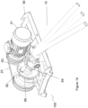
- FIGS. 1a , 1b and 2 show a preferred distribution apparatus, generally referred to herein by reference numeral 100.
- distribution apparatus 100 comprises oscillating means 60, motor 21 connected to oscillating means 60 and protruding element 10 attached to oscillating means 60 for oscillatory movement thereof.
- Distribution apparatus 100 is shown mounted on frame 90 for attachment between an upper conveyor member and downstream conveyor member. Frame 90 is shown in Figure 8 .
- Oscillating means 60 comprises rotating flywheel 61 provided with offset bearing 62 for creating a cam effect when rotated.
- Rotating flywheel 61 is rotated by electric motor 21 through pulleys 22 and belt 23.
- Bar 63 is attached to rotating flywheel 61 at offset bearing 62 and connects follower fork 64 to rotating flywheel 61.
- As rotating flywheel 61 rotates, bar 63 moves in a circular motion about the centre of flywheel 61.
- the horizontal movement component of this circular motion is transferred to protruding element 10 via follower fork 64 and base plate 67 to which protruding element 10 is bolted, while the vertical movement is removed by bearings 65 at the end of follower fork 64.
- offset bearing 62 and the centre of flywheel 61 may be adjusted by means of rotating bearing 62 in eccentric collar 68 of flywheel 61, therefore adjusting the stroke.
- preferred protruding element 10 of distribution apparatus 100 comprises three elongate hollow poles 11 each connected at one end to end plate 12 such that the free ends of poles 11 splay out in a fan like fashion.
- Reinforcing brackets 13 extend from end plate 12 along at least a portion of the underside of each pole 11.
- Poles 11 are attached to end plate 12 such that they point downwards at an angle ⁇ from the orthogonal position and are separated from one another by an angle ⁇ .
- Poles 11, end plate 12 and reinforcing brackets 13 as shown in the Figures are each made of mild steel.
- each pole 11 is of 48.3 mm diameter with a 3.2 mm thick wall, i.e. 48.3 mm x 3.2 mm circular hollow section, and end plate 12 and reinforcing brackets 13 are each 6 mm thick.
- this is not considered to be limiting and any suitable size is contemplated to be within the scope of the invention.
- Distribution apparatus 100 is for distributing material from an upper conveyor member with a conveying portion of a first width to downstream conveyor member with a receiving portion of equal or greater width, wherein apparatus 100 is removably mountable, between the conveying portion and the receiving portion.
- Protruding element 10 is adapted to oscillate at a speed in the range of from 50 oscillations per minute to 250 oscillations per minute, preferably 180 oscillations per minute.
- FIGS 4 to 6 show a preferred waste handling machine according to the invention, generally referred to herein by reference numeral 500.
- Waste handling machine 500 has distribution apparatus 100 disposed between vibratory feeder 530 and speed-up conveyor 540.
- apparatus 100 is mounted adjacent receiving portion 541 of speed-up conveyor 540 such that end plate 12 and the portion of poles 11 reinforced by reinforcing brackets 13 are located under conveying portion 531 of vibratory feeder 530.
- Protruding element 10 of apparatus 100 extends substantially in the direction of conveyance of speed-up conveyor 540 and is adapted to oscillate in a direction transverse to the direction of conveyance of speed-up conveyor 540.
- Figures 7a and 7b show distribution apparatus 100 mounted to speed-up conveyor 540 of waste handling machine 500 via frame 90. Vibratory feeder 530 has been removed from this Figure for clarity.
- distribution apparatus 100 is shown to receive material from conveying portion 531 at any angle of 0°. This is a result of vibratory feeder 530 and speed-up conveyor 540 being in line such that protruding element 10 extends substantially in the direction of conveyance of vibratory feeder 530. However, this is not to be considered limiting and vibratory feeder 530 may instead be placed at an alternative angle to speed-up conveyor 540, e.g. at 90° thereto.
- Figure 8 shows a preferred mount 90 for attaching distribution apparatus 100 to speed-up conveyor 540.
- Figures 9a to 9c show an alternative preferred distribution apparatus, generally referred to herein by reference numeral 200, incorporated in material handling machine 600 according to the invention.
- apparatus 200 comprises protruding element 210 drivable in oscillation about a vertical axis by drive mechanism 20.
- Protruding element 210 comprises an elongate hollow pole 211 attached to follower fork 25 of drive mechanism 20.
- Distribution apparatus 200 is shown attached to machine 600 between upper conveyor 630 and lower conveyor 640 such that apparatus 200 distributes material from conveying portion 631 of upper conveyor 630 to receiving portion 641 of lower conveyor 640.
- elongate pole 211 of apparatus 200 extends through an aperture (not shown) of angled bracket 214.
- Angled bracket 214 has top section 215 for attachment to upper conveyor 630, shorter base section 216 for attachment to downstream conveyor 640 and mid-section 217 containing the aperture through which elongate pole 211 extends.
- Top section 215 and base section 216 are parallel to each other with mid-section 217 connecting the two such that the angle between top section 215 and mid-section 217 is about 135°.
- protruding element 210 extends in the direction of conveyance of upper conveyor 630 thus receiving material at an angle of 0°.
- protruding element 210 also extends in the direction of conveyance of lower conveyor 640 and is adapted to oscillate in a direction transverse to said direction of conveyance.
- angled bracket 214 is mounted underneath upper conveyor 630 such that protruding element 210 extends through mid-section 217 and is above receiving portion 641 of lower conveyor 640.
- FIGS 10a and 10b show distribution apparatus 200 incorporated in material handling machine 700 according to the invention.
- Distribution apparatus 200 is shown attached to machine 700 under chute 750 and between upper conveyor 730 and lower conveyor 740 such that apparatus 200 distributes material received from conveying portion 731 of upper conveyor 730 to receiving portion 741 of lower conveyor 740.
- apparatus 200 is shown mounted above receiving portion 741 of lower conveyor 740.
- the arrows on upper conveyor 730 and lower conveyor 740 in Figure 10a show the respective directions of conveyance.
- Protruding element 210 extends in the direction of conveyance of lower conveyor 740.
- the arrows adjacent protruding element 210 in Figure 10a show how protruding element 210 oscillates back and forth in a direction transverse to the direction of conveyance of lower conveyor 740.
- upper conveyor 730 is at an angle of 45° to lower conveyor 740
- chute 750 ensures that protruding element 210 receives material at an angle of 0°.
- Figures 11a to 11c show distribution apparatus 200 incorporated in material handling machine 800 according to the invention.
- Apparatus 200 is shown attached to machine 800 under chute 850 and between two upper conveyors 830 and lower conveyor 840 such that apparatus 200 distributes material from conveying portions 731 of each upper conveyor 730 to receiving portion 841 of lower conveyor 840.
- apparatus 200 is shown mounted above receiving portion 841 of lower conveyor 840.
- the arrows on upper conveyors 830 and lower conveyor 840 in Figures 11a and 11b show the respective directions of conveyance.
- Protruding element 210 extends in the direction of conveyance of lower conveyor 840.
- the arrows adjacent protruding element 210 in Figures 11a and 11b show how protruding element 210 oscillates back and forth in a direction transverse to the direction of conveyance of lower conveyor 840.
- upper conveyors 830 are at an angle of 45° and 135°, to lower conveyor 740, respectively, chute 850 ensures that protruding element 210 receives material at an angle of 0°.
- Figure 12 shows distribution apparatus 200 incorporated in material handling machine 900 according to the invention.
- Apparatus 200 is shown attached to machine 900 between upper conveyor 930 and lower conveyor 940 such that apparatus 200 distributes material from conveying portion 931 of upper conveyor 930 to receiving portion 941 of downstream conveyor 940.
- protruding element 210 extends in the direction of conveyance of upper conveyor 930 thus receiving material at an angle of 0° and is adapted to oscillate in a direction transverse to said direction of conveyance.
- protruding element 210 extends in the opposite direction to the direction of conveyance of lower 940.
- apparatus 200 is mounted under conveying portion 931 of upper conveyor 930 such that protruding element 210 is above receiving portion 941 of lower conveyor 940.
Landscapes
- Engineering & Computer Science (AREA)
- Mechanical Engineering (AREA)
- Jigging Conveyors (AREA)
Claims (15)
- Maschine (500, 600, 700, 800, 900) zur Handhabung von Abfallmaterial, wobei die Maschine ein oberes Förderglied (530, 630, 730, 830, 930) mit einem Förderabschnitt (531, 631, 731, 831, 931) einer ersten Breite, ein nachgeschaltetes unteres Förderglied (540, 640, 740, 840, 940) mit einem Aufnahmeabschnitt (541, 641, 741, 841, 941) gleicher oder größerer Breite und eine Vorrichtung (100, 200) zum Verteilen von Material vom oberen Förderglied zum nachgeschalteten unteren Förderglied umfasst, wobei die Vorrichtung (100, 200) umfasst:eine Schwingeinrichtung (60),einen Antriebsmechanismus (20), der mit der Schwingeinrichtung verbunden ist; undein hervorstehendes Element (10, 210), das an der Schwingeinrichtung zur Schwingbewegung davon angebracht ist,wobei das hervorstehende Element ein hin- und hergehender Aufsatz ist, der dazu angepasst ist, in eine Richtung quer zur Richtung zu schwingen, in die er sich erstreckt,dadurch gekennzeichnet, dass die Vorrichtung zwischen dem Förderabschnitt des oberen Förderglieds und dem Aufnahmeabschnitt des nachgeschalteten unteren Förderglieds derart montierbar ist, dass sich das hervorstehende Element entweder im Wesentlichen in der Förderrichtung des nachgeschalteten Förderglieds oder sowohl in der Förderrichtung des oberen Förderglieds (530, 630, 730, 830) als auch entgegengesetzt zur Förderrichtung des nachgeschalteten Förderglieds erstreckt; undwobei das schwingende hervorstehende Element im Gebrauch in eine Richtung quer zur Förderrichtung des nachgeschalteten Förderglieds (540, 640, 740, 840, 940) mit einer Geschwindigkeit von 50 Schwingungen pro Minute bis 250 Schwingungen pro Minute schwingt und Material schüttelt, das vom oberen Förderglied auf das nachgeschaltete untere Förderglied übertragen wird.
- Maschine (500, 600, 900) nach Anspruch 1, wobei sich das hervorstehende Element (10, 210) der Vorrichtung (100, 200) in der Förderrichtung des oberen Förderglieds (530, 630, 730, 830) erstreckt.
- Maschine (500) nach Anspruch 1 oder Anspruch 2, wobei das hervorstehende Element (10) der Vorrichtung (100) einen oder mehrere sich erstreckende Abschnitte (11) umfasst.
- Maschine (500) nach einem der Ansprüche 1 bis 3, wobei das hervorstehende Element (10) der Vorrichtung (100) drei sich erstreckende Abschnitte (11) umfasst.
- Maschine (500) nach einem der vorhergehenden Ansprüche, wobei das hervorstehende Element der Vorrichtung eine Vielzahl von sich erstreckenden Abschnitten (11) umfasst, die in einem Winkel α zueinander stehen.
- Maschine (500) nach Anspruch 5, wobei α im Bereich von 1° bis 20° liegt.
- Maschine (500) nach einem der Ansprüche 3 bis 6, wobei jeder sich erstreckende Abschnitt (11, 211) unabhängig einen Querschnitt aufweist, der aus einem kreisförmigen, L-förmigen, T-förmigen, U-förmigen, rechteckigen oder quadratischen Querschnitt ausgewählt ist.
- Maschine (500) nach Anspruch 7, wobei jeder sich erstreckende Abschnitt eine längliche Stange ist.
- Maschine (500) nach einem der Ansprüche 3 bis 8, wobei die Vorrichtung (100) ferner eine Endplatte (12) umfasst und jeder sich erstreckende Abschnitt (11) derart an der Endplatte angebracht ist, dass jeder sich erstreckende Abschnitt (11) nach unten zeigt.
- Maschine (500) nach Anspruch 9, wobei jeder sich erstreckende Abschnitt (11) derart an der Endplatte (12) angebracht ist, dass jeder sich erstreckende Abschnitt (11) in einem Winkel β von der orthogonalen Position nach unten zeigt, wobei β im Bereich von 2° bis 25° von der orthogonalen Position liegt.
- Maschine (500, 600, 700, 800, 900) nach einem der vorhergehenden Ansprüche, wobei das hervorstehende Element (10, 210) der Vorrichtung (100, 200) dazu angepasst ist, mit einer Geschwindigkeit von 180 Schwingungen pro Minute zu schwingen.
- Maschine (500, 600, 700, 800, 900) nach einem der vorhergehenden Ansprüche, wobei der Antriebsmechanismus (20) der Vorrichtung (100, 200) einen Elektromotor (21) umfasst.
- Maschine (500, 600, 700, 800, 900) nach einem der vorhergehenden Ansprüche, wobei die Schwingeinrichtung (60) der Vorrichtung ein rotierendes Schwungrad (61) und einen hin- und hergehenden Arm umfasst.
- Maschine (500, 600, 700, 800, 900) nach einem der vorhergehenden Ansprüche, wobei das obere Förderglied (530, 630, 730, 830, 930) einen Schneckenförderer, einen Vibrationsförderer oder ein Förderband umfasst.
- Maschine (500, 600, 700, 800, 900) nach einem der vorhergehenden Ansprüche, wobei das nachgeschaltete untere Förderglied (540, 640, 740, 840, 940) ein Förderband, einen Vibrationsförderer, eine Siebmaschine oder einen Schredder umfasst.
Applications Claiming Priority (2)
| Application Number | Priority Date | Filing Date | Title |
|---|---|---|---|
| GB1818403.6A GB2578896A (en) | 2018-11-12 | 2018-11-12 | Distribution apparatus |
| PCT/EP2019/080095 WO2020099168A1 (en) | 2018-11-12 | 2019-11-04 | Distribution apparatus |
Publications (2)
| Publication Number | Publication Date |
|---|---|
| EP3887294A1 EP3887294A1 (de) | 2021-10-06 |
| EP3887294B1 true EP3887294B1 (de) | 2024-09-11 |
Family
ID=64739435
Family Applications (1)
| Application Number | Title | Priority Date | Filing Date |
|---|---|---|---|
| EP19808987.2A Active EP3887294B1 (de) | 2018-11-12 | 2019-11-04 | Verteilungsvorrichtung |
Country Status (4)
| Country | Link |
|---|---|
| US (1) | US11795006B2 (de) |
| EP (1) | EP3887294B1 (de) |
| GB (1) | GB2578896A (de) |
| WO (1) | WO2020099168A1 (de) |
Families Citing this family (1)
| Publication number | Priority date | Publication date | Assignee | Title |
|---|---|---|---|---|
| CN119349287B (zh) * | 2024-12-27 | 2025-03-25 | 靖江太和港务有限公司 | 一种货物装卸平台 |
Family Cites Families (10)
| Publication number | Priority date | Publication date | Assignee | Title |
|---|---|---|---|---|
| US3773165A (en) * | 1971-08-17 | 1973-11-20 | Creamette Co | Macaroni distributor shaker |
| GB1401631A (en) | 1972-01-25 | 1975-07-16 | Gough & Co Ltd | Vibratory apparatus |
| US4846676A (en) * | 1987-03-31 | 1989-07-11 | General Kinematics Corporation | Oscillating discharge chute |
| JP3144163B2 (ja) * | 1992-07-20 | 2001-03-12 | 住友電気工業株式会社 | 粉体材料の定量供給装置及び粉体材料圧縮製品の製造方法 |
| DE102010016735A1 (de) | 2010-03-19 | 2011-09-22 | WESTERIA Fördertechnik GmbH | Windsichter mit Verteilertellern |
| CA2823591A1 (en) * | 2013-08-14 | 2015-02-14 | Beaver Machine Corporation | Product singulating system and apparatus |
| CN205034813U (zh) * | 2015-09-28 | 2016-02-17 | 重庆帝安农业发展有限公司 | 自动摊平机 |
| CN205114582U (zh) * | 2015-10-26 | 2016-03-30 | 厦门市联谊吉源环保工程有限公司 | 一种垃圾布料装置 |
| CN107673089A (zh) * | 2017-09-15 | 2018-02-09 | 霍山县叶王农机制造有限公司 | 一种用于加工成品茶叶的均摊装置 |
| CN108584385A (zh) * | 2018-05-21 | 2018-09-28 | 滁州荣邦智能装备有限公司 | 一种物流包装用旋转存储自动分流台 |
-
2018
- 2018-11-12 GB GB1818403.6A patent/GB2578896A/en not_active Withdrawn
-
2019
- 2019-11-04 WO PCT/EP2019/080095 patent/WO2020099168A1/en not_active Ceased
- 2019-11-04 US US17/293,037 patent/US11795006B2/en active Active
- 2019-11-04 EP EP19808987.2A patent/EP3887294B1/de active Active
Also Published As
| Publication number | Publication date |
|---|---|
| EP3887294A1 (de) | 2021-10-06 |
| GB201818403D0 (en) | 2018-12-26 |
| GB2578896A (en) | 2020-06-03 |
| US20220002094A1 (en) | 2022-01-06 |
| US11795006B2 (en) | 2023-10-24 |
| WO2020099168A1 (en) | 2020-05-22 |
Similar Documents
| Publication | Publication Date | Title |
|---|---|---|
| JPS61501687A (ja) | ふるい装置 | |
| EP0198685B1 (de) | Maschine zum Aufschlitzen und Entleeren von Säcken | |
| AU724466B2 (en) | Sorting waste materials | |
| EP0793544B1 (de) | Vorrichtung zum sieben von partikeln | |
| JPH0253330B2 (de) | ||
| EP3887294B1 (de) | Verteilungsvorrichtung | |
| JP2935826B2 (ja) | 揺動選別機 | |
| KR100863605B1 (ko) | 다단 각도변화를 갖는 순환골재 선별용 스크린을 이용하여건설폐기물 중간처리과정중 파분쇄된 건설폐기물로부터순환골재를 생산하는 장치 | |
| US5588534A (en) | Garbage separator system | |
| RU2051757C1 (ru) | Сепаратор | |
| JP2003300019A (ja) | 振動篩機とそれを備えた篩設備 | |
| JP2001058159A (ja) | 長さ選別装置 | |
| JP2017213491A (ja) | 揺動選別機 | |
| EP3615232B1 (de) | System comprising a treatment device | |
| GB2188567A (en) | Screening apparatus | |
| JP7212986B2 (ja) | 直進フィーダ用のトラフ及びこれを備えた組合せ秤 | |
| JP3831552B2 (ja) | 廃石膏ボ−ド破砕分別処理装置 | |
| JPH10277491A (ja) | ごみ選別装置 | |
| JP2006150313A (ja) | 生葉の篩分装置 | |
| KR20070008447A (ko) | 다수의 빔이 설치된 휘다 | |
| JPH08323289A (ja) | 振動選別装置 | |
| JP2021169064A (ja) | 篩分け装置 | |
| GB2329136A (en) | Sorting grate | |
| CN205183169U (zh) | 一种塑料除砂机 | |
| CN219503265U (zh) | 一种选矿设备 |
Legal Events
| Date | Code | Title | Description |
|---|---|---|---|
| STAA | Information on the status of an ep patent application or granted ep patent |
Free format text: STATUS: UNKNOWN |
|
| STAA | Information on the status of an ep patent application or granted ep patent |
Free format text: STATUS: THE INTERNATIONAL PUBLICATION HAS BEEN MADE |
|
| PUAI | Public reference made under article 153(3) epc to a published international application that has entered the european phase |
Free format text: ORIGINAL CODE: 0009012 |
|
| STAA | Information on the status of an ep patent application or granted ep patent |
Free format text: STATUS: REQUEST FOR EXAMINATION WAS MADE |
|
| 17P | Request for examination filed |
Effective date: 20210614 |
|
| AK | Designated contracting states |
Kind code of ref document: A1 Designated state(s): AL AT BE BG CH CY CZ DE DK EE ES FI FR GB GR HR HU IE IS IT LI LT LU LV MC MK MT NL NO PL PT RO RS SE SI SK SM TR |
|
| DAV | Request for validation of the european patent (deleted) | ||
| DAX | Request for extension of the european patent (deleted) | ||
| GRAP | Despatch of communication of intention to grant a patent |
Free format text: ORIGINAL CODE: EPIDOSNIGR1 |
|
| STAA | Information on the status of an ep patent application or granted ep patent |
Free format text: STATUS: GRANT OF PATENT IS INTENDED |
|
| INTG | Intention to grant announced |
Effective date: 20240430 |
|
| GRAS | Grant fee paid |
Free format text: ORIGINAL CODE: EPIDOSNIGR3 |
|
| GRAA | (expected) grant |
Free format text: ORIGINAL CODE: 0009210 |
|
| STAA | Information on the status of an ep patent application or granted ep patent |
Free format text: STATUS: THE PATENT HAS BEEN GRANTED |
|
| AK | Designated contracting states |
Kind code of ref document: B1 Designated state(s): AL AT BE BG CH CY CZ DE DK EE ES FI FR GB GR HR HU IE IS IT LI LT LU LV MC MK MT NL NO PL PT RO RS SE SI SK SM TR |
|
| REG | Reference to a national code |
Ref country code: GB Ref legal event code: FG4D |
|
| REG | Reference to a national code |
Ref country code: CH Ref legal event code: EP |
|
| REG | Reference to a national code |
Ref country code: DE Ref legal event code: R096 Ref document number: 602019058791 Country of ref document: DE |
|
| REG | Reference to a national code |
Ref country code: IE Ref legal event code: FG4D |
|
| REG | Reference to a national code |
Ref country code: LT Ref legal event code: MG9D |
|
| PG25 | Lapsed in a contracting state [announced via postgrant information from national office to epo] |
Ref country code: NO Free format text: LAPSE BECAUSE OF FAILURE TO SUBMIT A TRANSLATION OF THE DESCRIPTION OR TO PAY THE FEE WITHIN THE PRESCRIBED TIME-LIMIT Effective date: 20241211 |
|
| REG | Reference to a national code |
Ref country code: NL Ref legal event code: MP Effective date: 20240911 |
|
| PG25 | Lapsed in a contracting state [announced via postgrant information from national office to epo] |
Ref country code: GR Free format text: LAPSE BECAUSE OF FAILURE TO SUBMIT A TRANSLATION OF THE DESCRIPTION OR TO PAY THE FEE WITHIN THE PRESCRIBED TIME-LIMIT Effective date: 20241212 Ref country code: FI Free format text: LAPSE BECAUSE OF FAILURE TO SUBMIT A TRANSLATION OF THE DESCRIPTION OR TO PAY THE FEE WITHIN THE PRESCRIBED TIME-LIMIT Effective date: 20240911 |
|
| PG25 | Lapsed in a contracting state [announced via postgrant information from national office to epo] |
Ref country code: BG Free format text: LAPSE BECAUSE OF FAILURE TO SUBMIT A TRANSLATION OF THE DESCRIPTION OR TO PAY THE FEE WITHIN THE PRESCRIBED TIME-LIMIT Effective date: 20240911 |
|
| PG25 | Lapsed in a contracting state [announced via postgrant information from national office to epo] |
Ref country code: LV Free format text: LAPSE BECAUSE OF FAILURE TO SUBMIT A TRANSLATION OF THE DESCRIPTION OR TO PAY THE FEE WITHIN THE PRESCRIBED TIME-LIMIT Effective date: 20240911 |
|
| PG25 | Lapsed in a contracting state [announced via postgrant information from national office to epo] |
Ref country code: HR Free format text: LAPSE BECAUSE OF FAILURE TO SUBMIT A TRANSLATION OF THE DESCRIPTION OR TO PAY THE FEE WITHIN THE PRESCRIBED TIME-LIMIT Effective date: 20240911 |
|
| PG25 | Lapsed in a contracting state [announced via postgrant information from national office to epo] |
Ref country code: RS Free format text: LAPSE BECAUSE OF FAILURE TO SUBMIT A TRANSLATION OF THE DESCRIPTION OR TO PAY THE FEE WITHIN THE PRESCRIBED TIME-LIMIT Effective date: 20241211 Ref country code: ES Free format text: LAPSE BECAUSE OF FAILURE TO SUBMIT A TRANSLATION OF THE DESCRIPTION OR TO PAY THE FEE WITHIN THE PRESCRIBED TIME-LIMIT Effective date: 20240911 |
|
| PG25 | Lapsed in a contracting state [announced via postgrant information from national office to epo] |
Ref country code: RS Free format text: LAPSE BECAUSE OF FAILURE TO SUBMIT A TRANSLATION OF THE DESCRIPTION OR TO PAY THE FEE WITHIN THE PRESCRIBED TIME-LIMIT Effective date: 20241211 Ref country code: NO Free format text: LAPSE BECAUSE OF FAILURE TO SUBMIT A TRANSLATION OF THE DESCRIPTION OR TO PAY THE FEE WITHIN THE PRESCRIBED TIME-LIMIT Effective date: 20241211 Ref country code: LV Free format text: LAPSE BECAUSE OF FAILURE TO SUBMIT A TRANSLATION OF THE DESCRIPTION OR TO PAY THE FEE WITHIN THE PRESCRIBED TIME-LIMIT Effective date: 20240911 Ref country code: HR Free format text: LAPSE BECAUSE OF FAILURE TO SUBMIT A TRANSLATION OF THE DESCRIPTION OR TO PAY THE FEE WITHIN THE PRESCRIBED TIME-LIMIT Effective date: 20240911 Ref country code: GR Free format text: LAPSE BECAUSE OF FAILURE TO SUBMIT A TRANSLATION OF THE DESCRIPTION OR TO PAY THE FEE WITHIN THE PRESCRIBED TIME-LIMIT Effective date: 20241212 Ref country code: FI Free format text: LAPSE BECAUSE OF FAILURE TO SUBMIT A TRANSLATION OF THE DESCRIPTION OR TO PAY THE FEE WITHIN THE PRESCRIBED TIME-LIMIT Effective date: 20240911 Ref country code: ES Free format text: LAPSE BECAUSE OF FAILURE TO SUBMIT A TRANSLATION OF THE DESCRIPTION OR TO PAY THE FEE WITHIN THE PRESCRIBED TIME-LIMIT Effective date: 20240911 Ref country code: BG Free format text: LAPSE BECAUSE OF FAILURE TO SUBMIT A TRANSLATION OF THE DESCRIPTION OR TO PAY THE FEE WITHIN THE PRESCRIBED TIME-LIMIT Effective date: 20240911 |
|
| REG | Reference to a national code |
Ref country code: AT Ref legal event code: MK05 Ref document number: 1722530 Country of ref document: AT Kind code of ref document: T Effective date: 20240911 |
|
| PG25 | Lapsed in a contracting state [announced via postgrant information from national office to epo] |
Ref country code: NL Free format text: LAPSE BECAUSE OF FAILURE TO SUBMIT A TRANSLATION OF THE DESCRIPTION OR TO PAY THE FEE WITHIN THE PRESCRIBED TIME-LIMIT Effective date: 20240911 |
|
| PG25 | Lapsed in a contracting state [announced via postgrant information from national office to epo] |
Ref country code: IS Free format text: LAPSE BECAUSE OF FAILURE TO SUBMIT A TRANSLATION OF THE DESCRIPTION OR TO PAY THE FEE WITHIN THE PRESCRIBED TIME-LIMIT Effective date: 20250111 Ref country code: PT Free format text: LAPSE BECAUSE OF FAILURE TO SUBMIT A TRANSLATION OF THE DESCRIPTION OR TO PAY THE FEE WITHIN THE PRESCRIBED TIME-LIMIT Effective date: 20250113 |
|
| PG25 | Lapsed in a contracting state [announced via postgrant information from national office to epo] |
Ref country code: RO Free format text: LAPSE BECAUSE OF FAILURE TO SUBMIT A TRANSLATION OF THE DESCRIPTION OR TO PAY THE FEE WITHIN THE PRESCRIBED TIME-LIMIT Effective date: 20240911 Ref country code: SM Free format text: LAPSE BECAUSE OF FAILURE TO SUBMIT A TRANSLATION OF THE DESCRIPTION OR TO PAY THE FEE WITHIN THE PRESCRIBED TIME-LIMIT Effective date: 20240911 |
|
| PG25 | Lapsed in a contracting state [announced via postgrant information from national office to epo] |
Ref country code: AT Free format text: LAPSE BECAUSE OF FAILURE TO SUBMIT A TRANSLATION OF THE DESCRIPTION OR TO PAY THE FEE WITHIN THE PRESCRIBED TIME-LIMIT Effective date: 20240911 Ref country code: EE Free format text: LAPSE BECAUSE OF FAILURE TO SUBMIT A TRANSLATION OF THE DESCRIPTION OR TO PAY THE FEE WITHIN THE PRESCRIBED TIME-LIMIT Effective date: 20240911 |
|
| PG25 | Lapsed in a contracting state [announced via postgrant information from national office to epo] |
Ref country code: PL Free format text: LAPSE BECAUSE OF FAILURE TO SUBMIT A TRANSLATION OF THE DESCRIPTION OR TO PAY THE FEE WITHIN THE PRESCRIBED TIME-LIMIT Effective date: 20240911 Ref country code: CZ Free format text: LAPSE BECAUSE OF FAILURE TO SUBMIT A TRANSLATION OF THE DESCRIPTION OR TO PAY THE FEE WITHIN THE PRESCRIBED TIME-LIMIT Effective date: 20240911 |
|
| PG25 | Lapsed in a contracting state [announced via postgrant information from national office to epo] |
Ref country code: IT Free format text: LAPSE BECAUSE OF FAILURE TO SUBMIT A TRANSLATION OF THE DESCRIPTION OR TO PAY THE FEE WITHIN THE PRESCRIBED TIME-LIMIT Effective date: 20240911 Ref country code: SK Free format text: LAPSE BECAUSE OF FAILURE TO SUBMIT A TRANSLATION OF THE DESCRIPTION OR TO PAY THE FEE WITHIN THE PRESCRIBED TIME-LIMIT Effective date: 20240911 |
|
| REG | Reference to a national code |
Ref country code: DE Ref legal event code: R119 Ref document number: 602019058791 Country of ref document: DE |
|
| REG | Reference to a national code |
Ref country code: CH Ref legal event code: PL |
|
| PG25 | Lapsed in a contracting state [announced via postgrant information from national office to epo] |
Ref country code: MC Free format text: LAPSE BECAUSE OF FAILURE TO SUBMIT A TRANSLATION OF THE DESCRIPTION OR TO PAY THE FEE WITHIN THE PRESCRIBED TIME-LIMIT Effective date: 20240911 |
|
| PG25 | Lapsed in a contracting state [announced via postgrant information from national office to epo] |
Ref country code: DK Free format text: LAPSE BECAUSE OF FAILURE TO SUBMIT A TRANSLATION OF THE DESCRIPTION OR TO PAY THE FEE WITHIN THE PRESCRIBED TIME-LIMIT Effective date: 20240911 |
|
| PG25 | Lapsed in a contracting state [announced via postgrant information from national office to epo] |
Ref country code: LU Free format text: LAPSE BECAUSE OF NON-PAYMENT OF DUE FEES Effective date: 20241104 |
|
| REG | Reference to a national code |
Ref country code: CH Ref legal event code: PL |
|
| PLBE | No opposition filed within time limit |
Free format text: ORIGINAL CODE: 0009261 |
|
| STAA | Information on the status of an ep patent application or granted ep patent |
Free format text: STATUS: NO OPPOSITION FILED WITHIN TIME LIMIT |
|
| PG25 | Lapsed in a contracting state [announced via postgrant information from national office to epo] |
Ref country code: CH Free format text: LAPSE BECAUSE OF NON-PAYMENT OF DUE FEES Effective date: 20241130 |
|
| 26N | No opposition filed |
Effective date: 20250612 |
|
| GBPC | Gb: european patent ceased through non-payment of renewal fee |
Effective date: 20241211 |
|
| REG | Reference to a national code |
Ref country code: BE Ref legal event code: MM Effective date: 20241130 |
|
| PG25 | Lapsed in a contracting state [announced via postgrant information from national office to epo] |
Ref country code: SE Free format text: LAPSE BECAUSE OF FAILURE TO SUBMIT A TRANSLATION OF THE DESCRIPTION OR TO PAY THE FEE WITHIN THE PRESCRIBED TIME-LIMIT Effective date: 20240911 |
|
| PG25 | Lapsed in a contracting state [announced via postgrant information from national office to epo] |
Ref country code: DE Free format text: LAPSE BECAUSE OF NON-PAYMENT OF DUE FEES Effective date: 20250603 |
|
| PG25 | Lapsed in a contracting state [announced via postgrant information from national office to epo] |
Ref country code: BE Free format text: LAPSE BECAUSE OF NON-PAYMENT OF DUE FEES Effective date: 20241130 Ref country code: GB Free format text: LAPSE BECAUSE OF NON-PAYMENT OF DUE FEES Effective date: 20241211 |
|
| PG25 | Lapsed in a contracting state [announced via postgrant information from national office to epo] |
Ref country code: FR Free format text: LAPSE BECAUSE OF NON-PAYMENT OF DUE FEES Effective date: 20241111 |
|
| PG25 | Lapsed in a contracting state [announced via postgrant information from national office to epo] |
Ref country code: IE Free format text: LAPSE BECAUSE OF NON-PAYMENT OF DUE FEES Effective date: 20241104 |