EP3885859A1 - Increasing production yield of coated wire elements - Google Patents
Increasing production yield of coated wire elements Download PDFInfo
- Publication number
- EP3885859A1 EP3885859A1 EP20166510.6A EP20166510A EP3885859A1 EP 3885859 A1 EP3885859 A1 EP 3885859A1 EP 20166510 A EP20166510 A EP 20166510A EP 3885859 A1 EP3885859 A1 EP 3885859A1
- Authority
- EP
- European Patent Office
- Prior art keywords
- wire
- layer
- coated wire
- coated
- defects
- Prior art date
- Legal status (The legal status is an assumption and is not a legal conclusion. Google has not performed a legal analysis and makes no representation as to the accuracy of the status listed.)
- Pending
Links
Images



Classifications
-
- G—PHYSICS
- G05—CONTROLLING; REGULATING
- G05B—CONTROL OR REGULATING SYSTEMS IN GENERAL; FUNCTIONAL ELEMENTS OF SUCH SYSTEMS; MONITORING OR TESTING ARRANGEMENTS FOR SUCH SYSTEMS OR ELEMENTS
- G05B19/00—Program-control systems
- G05B19/02—Program-control systems electric
- G05B19/418—Total factory control, i.e. centrally controlling a plurality of machines, e.g. direct or distributed numerical control [DNC], flexible manufacturing systems [FMS], integrated manufacturing systems [IMS] or computer integrated manufacturing [CIM]
- G05B19/41875—Total factory control, i.e. centrally controlling a plurality of machines, e.g. direct or distributed numerical control [DNC], flexible manufacturing systems [FMS], integrated manufacturing systems [IMS] or computer integrated manufacturing [CIM] characterised by quality surveillance of production
-
- H—ELECTRICITY
- H01—ELECTRIC ELEMENTS
- H01B—CABLES; CONDUCTORS; INSULATORS; SELECTION OF MATERIALS FOR THEIR CONDUCTIVE, INSULATING OR DIELECTRIC PROPERTIES
- H01B13/00—Apparatus or processes specially adapted for manufacturing conductors or cables
- H01B13/06—Insulating conductors or cables
-
- B—PERFORMING OPERATIONS; TRANSPORTING
- B05—SPRAYING OR ATOMISING IN GENERAL; APPLYING FLUENT MATERIALS TO SURFACES, IN GENERAL
- B05D—PROCESSES FOR APPLYING FLUENT MATERIALS TO SURFACES, IN GENERAL
- B05D5/00—Processes for applying liquids or other fluent materials to surfaces to obtain special surface effects, finishes or structures
- B05D5/005—Repairing damaged coatings
-
- B—PERFORMING OPERATIONS; TRANSPORTING
- B05—SPRAYING OR ATOMISING IN GENERAL; APPLYING FLUENT MATERIALS TO SURFACES, IN GENERAL
- B05D—PROCESSES FOR APPLYING FLUENT MATERIALS TO SURFACES, IN GENERAL
- B05D7/00—Processes, other than flocking, specially adapted for applying liquids or other fluent materials to particular surfaces or for applying particular liquids or other fluent materials
- B05D7/20—Processes, other than flocking, specially adapted for applying liquids or other fluent materials to particular surfaces or for applying particular liquids or other fluent materials to wires
-
- H—ELECTRICITY
- H01—ELECTRIC ELEMENTS
- H01B—CABLES; CONDUCTORS; INSULATORS; SELECTION OF MATERIALS FOR THEIR CONDUCTIVE, INSULATING OR DIELECTRIC PROPERTIES
- H01B13/00—Apparatus or processes specially adapted for manufacturing conductors or cables
- H01B13/06—Insulating conductors or cables
- H01B13/16—Insulating conductors or cables by passing through or dipping in a liquid bath; by spraying
-
- H—ELECTRICITY
- H01—ELECTRIC ELEMENTS
- H01B—CABLES; CONDUCTORS; INSULATORS; SELECTION OF MATERIALS FOR THEIR CONDUCTIVE, INSULATING OR DIELECTRIC PROPERTIES
- H01B13/00—Apparatus or processes specially adapted for manufacturing conductors or cables
- H01B13/34—Apparatus or processes specially adapted for manufacturing conductors or cables for marking conductors or cables
-
- B—PERFORMING OPERATIONS; TRANSPORTING
- B05—SPRAYING OR ATOMISING IN GENERAL; APPLYING FLUENT MATERIALS TO SURFACES, IN GENERAL
- B05D—PROCESSES FOR APPLYING FLUENT MATERIALS TO SURFACES, IN GENERAL
- B05D2256/00—Wires or fibres
-
- Y—GENERAL TAGGING OF NEW TECHNOLOGICAL DEVELOPMENTS; GENERAL TAGGING OF CROSS-SECTIONAL TECHNOLOGIES SPANNING OVER SEVERAL SECTIONS OF THE IPC; TECHNICAL SUBJECTS COVERED BY FORMER USPC CROSS-REFERENCE ART COLLECTIONS [XRACs] AND DIGESTS
- Y02—TECHNOLOGIES OR APPLICATIONS FOR MITIGATION OR ADAPTATION AGAINST CLIMATE CHANGE
- Y02P—CLIMATE CHANGE MITIGATION TECHNOLOGIES IN THE PRODUCTION OR PROCESSING OF GOODS
- Y02P90/00—Enabling technologies with a potential contribution to greenhouse gas [GHG] emissions mitigation
- Y02P90/02—Total factory control, e.g. smart factories, flexible manufacturing systems [FMS] or integrated manufacturing systems [IMS]
Definitions
- Wire elements obtainable by coating a metal wire with at least one layer, are used in a number of electrical devices.
- electrical devices e.g ., electrical motors
- defects in the at least one layer are acceptable provided that the number of defects are kept below a specified number. These defects include, amongst others, scratches, pin-holes or bubbles.
- An object of the present invention is to at least partially overcome at least one of the disadvantages encountered in the state of the art.
- a metal wire comprising an inner metal core layer.
- the inner metal core layer comprises a metal or a metal alloy. It is particularly that the inner metal core layer comprises tantalum. It is also preferred that the metal wire further comprises an outer metal core layer. It is more preferred that the outer metal core layer surrounds the inner metal core layer. It is further preferred that the outer metal core layer comprises a metal or metal alloy. It is particularly preferred that the outer metal core layer comprises platinum. It is particularly preferred that the inner metal core layer, the outer metal core layer, or both, are electrically conducting.
- the metal wire is coated with a first layer to obtain a first coated wire.
- the first layer is an electrical insulator.
- the first coated wire is coated with a further layer to obtain a further coated wire.
- the further layer is electrically conducting.
- the another quality control process comprises the steps of testing at least one physical property of the metal wire.
- repeating units have the same length, this is not a requirement. It is also preferred that the length of the repeating unit is equal to the length of a wire element. Note that it is also not a requirement that all repeating units introduced in the further coated wire should have the same pattern. It is also preferred that the further wire comprises repeating units with at least two different repeating patterns.
- Repeating unit 204 has only the metal wire 201 and the further layer 203.
- a first defect was detected in the first layer 202 (see step 104 of Fig. 1 ) of a first coated wire.
- the first defect was marked (see step 105 of Fig. 1 ) by removing a longitudinal portion 209 of the first layer 202 from repeating unit 204. After removal of the first layer 202 in longitudinal portion 209, the first coated wire was coated with the further layer 203.
- Repeating units 204, 205, and 206 were then introduced to obtain the further coated wire 200.
- the variation in the diameter of the first coated wire, the further coated wire, and the wire elements are measured using an inspection means.
- the diameter is measured for every sub-section of a wire element.
- a metal wire with a diameter of 100 ⁇ m is provided.
- the metal wire comprises tantalum and platinum.
- the metal wire has an another length of 4000 m.
- the metal wire is coated with a first layer to obtain a first coated wire with a first length of 4000 m.
- the first layer consists of polyurethane, and has a first thickness of 25 ⁇ m.
- the first coated wire is subjected to a first quality control process in order to identify first defects.
- the first quality control process tests the dielectric strength of the first layer, as well as a first diameter of the first coated wire.
- the first quality control process also includes inspecting the first coated wire in order to identify bubbles or scratches in the first layer.
- the first layer is removed in a longitudinal portion using laser ablation. Every first defect is located in a longitudinal portion.
- the length of the longitudinal portions is 25 mm.
- the first layer and the further layer are removed in a repeating pattern, thereby introducing repeating units.
- the first layer and the further layer are removed using laser ablation. All repeating units have the same pattern, with the average length of a repeating unit being 25 mm.
- Every repeating unit consists of three subsections.
- the first subsection consists of the metal wire, the first layer, and the further layer.
- the second subsection consists of the metal wire and the first layer.
- the third subsection consists of the metal wire.
- the further coated wire is cut between every pair of neighbouring repeating units. A plurality of wire elements with an average length of 25 mm is thereby obtained.
- This example is a comparison of two methods for producing a plurality of wire elements.
- the first method is according to the present invention, as described in Example 1.
- the second method is according to the prior art, as described in the "Background" section.
- a difference between the present invention and the prior art is that the latter teaches that the first coated wire should be cut when first defects are identified. This is in contrast to the present invention, wherein the first coated wire is not cut.
- Table 1 is a comparison of the two methods. For the comparison, the following average quantities were measured:
Landscapes
- Engineering & Computer Science (AREA)
- Manufacturing & Machinery (AREA)
- Life Sciences & Earth Sciences (AREA)
- Wood Science & Technology (AREA)
- General Engineering & Computer Science (AREA)
- Quality & Reliability (AREA)
- Physics & Mathematics (AREA)
- General Physics & Mathematics (AREA)
- Automation & Control Theory (AREA)
- Investigating Materials By The Use Of Optical Means Adapted For Particular Applications (AREA)
Abstract
Description
- In general, the present invention relates to methods for coating wires. In particular, the present invention relates to a method for producing wire elements from coated wires. The present invention also relates in particular to a method for more reliably identifying and marking defects that occur during the production process of the wire elements. In particular, the present invention further relates to the wire elements that are produced by the method of the present invention.
- Wire elements, obtainable by coating a metal wire with at least one layer, are used in a number of electrical devices. For various electrical devices, e.g., electrical motors, defects in the at least one layer are acceptable provided that the number of defects are kept below a specified number. These defects include, amongst others, scratches, pin-holes or bubbles. However, for more specialised applications, e.g., using wire elements in medical devices or as electrochemical sensor elements, it is very important to use wire elements wherein the at least one layer is defect-free. This is to ensure that e.g., the medical devices provide very accurate measurements. It is therefore necessary to identify and mark any defects in the at least one layer that occur during the production of the wire elements.
- Wire elements used in medical applications often comprise three layers: an inner metal core layer, a first layer, and a further layer. The process of producing these three-layered, wire elements generally comprises the steps of coating a metal wire with a first layer to obtain a first coated wire. The first coated wire has a first length. In the next step, first defects in the first layer are identified. First defects are removed by cutting the first coated wire. This cutting results in at least two first coated wire segments, wherein every first coated wire segment has a segment length that is less than the first length. First coated wire segments that have at least one first defect are discarded. The remaining, first defect-free, first coated wire segments are then coated with a further layer to obtain further coated wire segments. The further coated wire segments are then used to produce the wire elements.
- The process described above is not very efficient. Firstly, the time needed to produce the wire elements increases with the number of first coated wire segments. Secondly, the cutting of the first coated wire to remove the first defects is often accompanied by a starting and stopping of production equipment, which can lead to a significant loss of production time. While the production time could possibly be partially reduced by adding additional production equipment, this has the negative effect of increasing production costs, as well as the complexity of the production process. Furthermore, removing the first defects by cutting the first coated wire leads to the loss of parts of the first coated wire that are defect free, thereby wasting potential wire elements.
- An object of the present invention is to at least partially overcome at least one of the disadvantages encountered in the state of the art.
- It is a further object of the invention to provide a method that decreases the time needed for producing a coated wire.
- It is a further object of the invention to provide a method that decreases the number of defects that occur during the production of a coated wire.
- It is a further object of the invention to provide a method that can reduce the dimensional variation, e.g., a diameter, of a coated wire.
- It is a further object of the invention to provide a method that reduces the energy required for coating a wire.
- It is a further object of the invention to provide a method that reduces the costs involved in producing a coated wire.
- It is a further object of the invention to provide a method that reduces the complexity of the production equipment needed for coating a wire.
- It is a further object of the invention to provide a method that reduces the time required for setting up the equipment used in coating a wire.
- It is a further object of the invention to provide a method that can be used to identify and mark defects during the coating of a wire.
- It is a further object of the invention to obtain defect-free coated wires.
- It is a further object of the invention to provide a method that decreases the time needed for producing wire elements.
- It is a further object of the invention to provide a method that decreases the number of defects that occur during the production of wire elements.
- It is a further object of the invention to provide a method that increases the production yield of defect-free wire elements.
- It is a further object of the invention to provide a method that can reduce the dimensional variation, e.g., a diameter, between the wire elements that are produced.
- It is a further object of the invention to provide a method that reduces the energy required for producing wire elements.
- It is a further object of the invention to provide a method that reduces the costs involved in producing wire elements.
- It is a further object of the invention to provide a method that reduces the complexity of the production equipment needed for producing wire elements.
- It is a further object of the invention to provide a method that reduces the time required for setting up the equipment used in producing wire elements.
- It is a further object of the invention to provide a method that can be used to identify and mark defects during the production of wire elements.
- It is a further object of the invention to obtain defect-free wire elements.
- It is a further object of the invention to use defect-free wire elements in medical devices in order to improve the reliability of the medical devices.
- It is a further object of the invention to obtain wire elements that have an increased life expectancy.
- A contribution to at least partially fulfilling at least one of the above-mentioned objects is made by the independent embodiments. The dependent embodiments provide preferred embodiments which contribute to at least partially fulfilling at least one of the objects.
- |1| A method for producing a plurality of wire elements, comprising the steps of
- a. providing a metal wire, wherein the metal wire comprises an inner metal core layer;
- b. coating the metal wire with a first layer to obtain a first coated wire, wherein the first layer has a first thickness;
- c. subjecting the first coated wire to a first quality control process;
- d. marking any first defects identified in the first quality control process, preferably by manipulating, more preferably by at least partially removing, the first layer;
- e. coating the first coated wire with a further layer to obtain a further coated wire, wherein the further layer has a further thickness;
- f. introducing two or more repeating units along the further coated wire by reducing the first thickness, the further thickness, or both;
- g. cutting the further coated wire between at least one pair, preferably all pairs, of neighbouring repeating units to obtain a plurality of wire elements;
wherein
prior to cutting the further coated wire in step g. to obtain the plurality of wire elements, a first length of the first coated wire is less than 10 %, preferably less than 5 %, and more preferably less than 1 %, longer than a further length of the further coated wire.
- |2| The method according to embodiment |1|, wherein, before the two or more repeating units are introduced, the following steps are performed:
- a. subjecting the further coated wire to a further quality control process;
- b. identifying further defects;
- c. marking the further defects, preferably by manipulating, more preferably by at least partially removing, either the further layer, the first layer, or both.
- |3| The method according to any of the preceding embodiments, wherein, after the two or more repeating units have been introduced, the following steps are performed:
- a. subjecting the repeating units to an additional quality control process;
- b. identifying additional defects;
- c. marking the repeating units that comprise at least one additional defect with a reject mark.
- |4| The method according to any of the preceding embodiments, wherein, prior to coating the metal wire with the first layer, the following steps are preformed:
- a. subjecting the metal wire to an another quality control process;
- b. identifying another defects;
- c. marking the another defects.
- |5| The method according to any of the preceding embodiments, wherein laser ablation is used for at least one or all of the following:
- a. marking the first defects, the further defects, or both;
- b. reducing the first thickness, the further thickness, or both;
- c. applying the reject mark.
- |6| The method according to any of the preceding embodiments, wherein the repeating units has a length in the range of 1 mm to 110 mm, preferably in the range of 2.5 mm to 80 mm, and more preferably in the range of 4 mm to 60 mm.
- |7| The method according to any of the preceding embodiments, wherein a repeating unit comprises, when moving along the length of the repeating unit, at least two sub-sections, more preferably at least five subsections, and further preferably at least seven subsections.
- |8| The method according to embodiment |7|, wherein at least one or all of the following varies between two neighbouring sub-sections:
- a. a diameter;
- b. the number of layers;
- c. the first thickness;
- d. the further thickness.
- |9| The method according to any of the preceding embodiments, wherein the first quality control process comprises at least one or all of the following:
- a. inspecting the first coated wire;
- b. testing at least one physical property of the first coated wire, preferably the dielectric strength;
- c. testing at least one dimensional property of the first coated wire, preferably the first length, a first diameter, or both.
- |10| The method according to any of the embodiments |2| to |9|, wherein the further quality control process comprises at least one or all of the following:
- a. inspecting the further coated wire;
- b. testing at least one dimensional property of the further coated wire, preferably the further length, a further diameter, or both.
- |11| The method according to any of the embodiments |3| to |10|, wherein the additional quality control process comprises at least one or all of the following:
- a. inspecting at least one, preferably all, repeating units;
- b. testing the number of subsections in at least one, preferably all, repeating units;
- c. testing at least one dimensional property of at least one, preferably all, repeating units. It is preferred that the at least one dimensional property comprises at least one or all of the following: at least one dimension parallel to the repeating unit, at least one dimension perpendicular to the repeating unit, or both.
- |12| The method according to any of the embodiments |4| to |11|, wherein the another quality control process comprises at least one or all of the following:
- a. inspecting the metal wire;
- b. testing at least one physical property of the metal wire, preferably electromagnetic properties, more preferably the electrical conductivity coefficient;
- c. testing at least one dimensional property of the metal wire, preferably an another length, an another diameter, or both.
- |13| The method according to any of the preceding embodiments, wherein the first length of the first coated wire is in the range of 1000 m to 6000 m, preferably in the range of 2000 m to 5000 m, and more preferably in the range of 2500 m to 4500 m.
- |14| The method according to any of the preceding embodiments, wherein the time required for performing steps b. through f. in embodiment |1| is in the range of 1 m/min to 900 m/min, preferably in the range of 5 m/min to 850 m/min, and more preferably in the range of 8.5 m/min to 600 m/min.
- |15| The method according to any of the preceding embodiments, wherein at least one or all of the following is true:
- a. at least 80 %, preferably at least 90 %, and more preferably at least 95 % of an another length of the metal wire is coated with the first layer;
- b. at least 80 %, preferably at least 90 %, and more preferably at least 95 % of the first length of the first coated wire is coated with the further layer.
- |16| The method according to any of the preceding embodiments, wherein the first layer, the further layer, or both, is applied by making use of at least one of the following:
- a. wire enamelling;
- b. extrusion.
- |17| The method according to any of the embodiments |5| to |16|, wherein the laser used for the laser ablation has at least one or all of the following properties:
- a. is a solid-state laser;
- b. peak wavelength in the range of 430 nm to 780 nm, preferably in the range of 470 nm to 640 nm, and more preferably in the range of 528 nm to 536 nm;
- c. spot size in the range of 5 µm to 50 µm, preferably in the range of 8 µm to 32 µm, and more preferably in the range of 10 µm to 20 µm;
- d. fluence in the range of 1.0 J/cm2 to 5.0 J/cm2, preferably in the range of 1.7 J/cm2 to 4.2 J/cm2, and more preferably in the range of 2.5 J/cm2 to 3.8 J/cm2.
- |18| The method according to embodiment |17|, wherein the laser is a pulsed laser with at least one or all of the following properties:
- a. a pulse duration in the range of 10 fs to 500 ns, preferably in the range of 500 fs to 310 ns, and more preferably in the range of 13 ns to 83 ns;
- b. an energy per pulse is in the range of 2 µJ to 15 µJ, preferably from 3 µJ to 12 µJ, most preferably from 4 µJ to 8 µJ;
- c. the laser is pulsed at a frequency in the range of 5 kHz to 600 kHz, preferably in the range of 60 kHz to 300 kHz, and more preferably in the range of 110 kHz to 190 kHz.
- |19| The method according to any of the preceding embodiments, wherein the first layer has at least one or all of the following properties:
- a. comprises an organic material, preferably a polymer, more preferably a material selected from the group consisting of polyurethane, polyimide, polytetrafluoroethylene, perfluoro alkoxy alkanes, ethylene tetrafluoroethylene, or a combination of two or more thereof;
- b. first thickness in the range of 10 µm to 40 µm, preferably in the range of 15 µm to 35 µm, and more preferably in the range of 20 µm to 30 µm;
- c. an electrical conductivity in the range of 10-21 S/m to 10-11 S/m, preferably in the range of 10-20 S/m to 10-12 S/m, and more preferably in the range of 5 x 10-20 S/m to 2 x 10-13 S/m.
- |20| The method according to any of the preceding embodiments, wherein the further layer has at least one or all of the following properties:
- a. comprises at least one metal, preferably silver, at least one a metal compound, preferably silver chloride, or a combination thereof;
- b. further thickness in the range of 4 µm to 30 µm, preferably in the range of 6 µm to 25 µm, and more preferably in the range of 8 µm to 22 µm;
- c. an electrical conductivity in the range of 10-8 S/m to 2 x 10⁻² S/m, preferably in 5 the range of 10-7 S/m to 10-3 S/m, and more preferably in the range of 5 x 10⁻⁷ S/m to 2 x 10⁻⁴ S/m;
- |21| The method according to any of the preceding embodiments, wherein the metal wire has at least one or all of the following properties:
- a. comprises a metal selected from the group consisting of iridium, gold, nickel, niobium, palladium, platinum, silver, titanium, tantalum, wolfram, or a combination of two or more thereof;
- b. an another diameter in the range of 40 µm to 260 µm, preferably in the range of 60 µm to 210 µm, and more preferably in the range of 80 µm to 170 µm;
- c. an electrical conductivity in the range of 104 S/m to 108 S/m, preferably in the range of 105 S/m to 5 x 10⁷ S/m, and more preferably in the range of 5 x 10⁵ S/m to 2 x 10⁷ S/m.
- |22| A further coated wire obtainable by a method according to any of the embodiments |1| to |21|, wherein the further coated wire comprises an inner metal core layer, a first layer, and a further layer.
- |23| The further coated wire according to embodiment |22|, wherein at least one or all of the following applies:
- a. the inner metal core layer comprises a metal selected from the group consisting of iridium, gold, nickel, niobium, palladium, platinum, silver, titanium, tantalum, wolfram, or a combination of two or more thereof;
- b. the first layer comprises an organic material, preferably a polymer, more preferably a material selected from the group consisting of polyurethane, polyimide, polytetrafluoroethylene, perfluoro alkoxy alkanes, ethylene tetrafluoroethylene, or a combination of two or more thereof;
- c. the further layer comprises at least one metal, preferably silver, at least one a metal compound, preferably silver chloride, or a combination thereof.
- |24| The further coated wire according to any of the embodiments |22| to |23|, wherein at least one or all of the following applies:
- a. the inner metal core layer has a thickness in the range of 40 µm to 260 µm, preferably in the range of 60 µm to 210 µm, and more preferably in the range of 80 µm to 170 µm;
- b. the first layer has a first thickness in the range of 10 µm to 40 µm, preferably in the range of 15 µm to 35 µm, and more preferably in the range of 20 µm to 30 µm;
- c. the further layer has a further thickness in the range of 4 µm to 30 µm, preferably in the range of 6 µm to 25 µm, and more preferably in the range of 8 µm to 22 µm.
- |25| The further coated wire according to any of the embodiments |22| to |24|, wherein the further coated wire comprises at least two repeating units.
- |26| The further coated wire according to embodiment |25|, wherein the at least two repeating units comprises, when moving along the length of the repeating unit, at least two, preferably at least five, and more preferably at least seven sub-sections, wherein a diameter of the repeating unit preferably varies between two neighbouring sub-sections.
- |27| A wire element obtainable by a method according to any of the embodiments |1| to |21|, wherein the wire elements preferably comprises an inner metal core layer, a first layer, and a further layer.
- |28| The wire element according to embodiment |27|, wherein the wire element comprises at least one or all of the following:
- a. the inner metal core layer comprises a metal selected from the group consisting of iridium, gold, nickel, niobium, palladium, platinum, silver, titanium, tantalum, wolfram, or a combination of two or more thereof;
- b. the first layer comprises an organic material, preferably a polymer, more preferably a material selected from the group consisting of polyurethane, polyimide, polytetrafluoroethylene, perfluoro alkoxy alkanes, ethylene tetrafluoroethylene, or a combination of two or more thereof;
- c. the further layer comprises at least one metal, preferably silver, or at least one a metal compound, preferably silver chloride, or a combination thereof.
- |29| The wire element according to any of the embodiment |27| to |28|, wherein at least one or all of the following applies:
- a. the inner metal core layer has a thickness in the range of 40 µm to 260 µm, preferably in the range of 60 µm to 210 µm, and more preferably in the range of 80 µm to 170 µm;
- b. the first layer has a first thickness in the range of 10 µm to 40 µm, preferably in the range of 15 µm to 35 µm, and more preferably in the range of 20 µm to 30 µm;
- c. the further layer has a further thickness in the range of 4 µm to 30 µm, preferably in the range of 6 µm to 25 µm, and more preferably in the range of 8 µm to 22 µm.
- |30| The wire element according to any of the embodiments |27| to |29|, wherein the wire element comprises, when moving along the length of the wire element, at least two, preferably at least five, and more preferably at least seven sub-sections, wherein a diameter of the wire element preferably varies between two neighbouring sub-sections.
- |31| A use of a wire element according to any of the embodiments |27| to |30| in an electrical device, preferably a medical device, more preferably a medical device used for measuring, and further preferably a medical device used for measuring blood glucose levels.
- |32| A use of a wire element according to any of the embodiments |27| to |30| as a sensor, preferably an electrochemical sensor, more preferably an electrochemical sensor for a medical device used for measuring, and further preferably an electrochemical sensor for a medical device used for measuring blood glucose levels.
- The present invention relates to a method for producing a plurality of wire elements. A "wire element" is defined as a longitudinal section that has been cut off from a wire. In this aspect it is preferred that the wire is a coated wire. A "coated wire" is defined as a metal wire that is coated with at least one layer.
- In the context of the present invention, examples of a "wire " include a metal wire, a first coated wire, and a further coated wire. Examples of a "coated wire " include a first coated wire and a further coated wire. Examples of a "layer" include a first layer, a further layer, and an additional layer. Examples of a "thickness" include a first thickness or a further thickness. Examples of "defects" include first defects, further defects, additional defects, and another defects. Examples of a "quality control process" include a first quality control process, a further quality control process, an additional quality control process, and an another quality control process. Examples of a "sub-section length" include a first sub-section length and a further sub-section length. Examples of a "diameter" include a first diameter, a further diameter, an even further diameter, a diameter of a repeating unit, and a diameter of a sub-section.
- In the present invention, if a cross-sectional cut is made of a wire or a repeating unit, then the cross-sectional cut will comprise at least one layer, e.g., the inner metal core layer, the first layer, the further layer. A "diameter" is defined as a total diameter of the cross-sectional cut, e.g. a total diameter of all the layers in the cross-sectional cut. A "thickness" of a layer is defined as a thickness of an individual layer. If the cross-sectional cut has only one layer, then the diameter will be equivalent to the thickness. If the cross-sectional cut has more than one layer, then the thickness of a layer will be less than the diameter.
- In a first aspect of the invention, a metal wire comprising an inner metal core layer is provided. In this aspect it is preferred that the inner metal core layer comprises a metal or a metal alloy. It is particularly that the inner metal core layer comprises tantalum. It is also preferred that the metal wire further comprises an outer metal core layer. It is more preferred that the outer metal core layer surrounds the inner metal core layer. It is further preferred that the outer metal core layer comprises a metal or metal alloy. It is particularly preferred that the outer metal core layer comprises platinum. It is particularly preferred that the inner metal core layer, the outer metal core layer, or both, are electrically conducting.
- In another aspect of the invention, the metal wire is coated with a first layer to obtain a first coated wire. In this aspect it is preferred that the first layer is an electrical insulator. In yet another aspect of the invention, the first coated wire is coated with a further layer to obtain a further coated wire. In this aspect, it is preferred that the further layer is electrically conducting.
- In an aspect of the invention, the first coated wire has a first length. It is preferred that the first length is a total length of the first coated wire, as measured between two endpoints of the first coated wire. In another aspect of the invention, the further coated wire has a further length. It is preferred that the further length is a total length of the further coated wire, as measured between two endpoints of the further coated wire. In another aspect of the invention, the metal wire has an another length. It is preferred that the another length is a total length of the metal wire, as measured between two endpoints of the metal wire.
- The coating of a metal wire or a coated wire is a well-known and established process in industry. The equipment for this process is commercially available from a number of companies e.g., Aumann AG (Germany) and Sicme Italie Impianti S.r.l (Italy). The coating can be obtained commercially from e.g., Axalta Coating Systems GmbH (Germany) and Elantas GmbH (Germany).
- In the context of the present invention, "first defects" are defects identified in the first coated wire. E.g., scratches, bubbles, or pin-holes in the first layer. E.g., a first diameter or the first length of the first coated wire falls outside of a first product specification range. "Further defects" are defects identified in the further coated wire. E.g., scratches, bubbles, or pin-holes in the further layer. E.g., a further diameter or the further length of the further coated wire falls outside of a further product specification range.
- In the context of the present invention, "additional defects" are defects identified in a repeating unit. E.g., a repeating unit wherein the first thickness of the first layer, the further thickness of the further layer, or both, has been insufficiently reduced. E.g., a repeating unit wherein a length of the repeating unit falls outside a product specification range. E.g., a repeating unit wherein a diameter of the repeating unit falls outside a product specification range. E.g., scratches, bubbles, or pin-holes in the first layer, the further layer, or both.
- In the context of the present invention, "another defects" are defects identified in the metal wire. E.g., scratches on the metal wire. E.g., an another diameter or an another length of the metal wire that falls outside of an another product specification range.
- In various embodiments of the present invention, a quality control process comprising the step of inspecting a wire is preferred. E.g., a further quality control process that comprises the step of inspecting the further coated wire. The "inspecting" of the wire should be understood to mean the identification of visible defects. E.g., visible defects include bubbles and scratches.
- The definition of "inspecting" applies, mutatis mutandis, to the repeating units. E.g., inspecting the repeating units for scratches in the metal wire, the first layer, the further layer, or all of the above. E.g., inspecting the repeating units for bubbles in the first layer, the further layer, or both.
- In a preferred embodiment, the additional quality control process comprises the steps of testing at least one dimensional property of at least one, preferably all, repeating units. In this aspect it is preferred to test the length of the repeating unit, the diameter of the repeating unit, or both, of at least one, preferably all, repeating units. It is also preferred to test the first thickness, the further thickness, or both, of at least one, preferably all, repeating units. If the repeating unit comprises sub-sections, it is further preferred to test a sub-section length, a diameter of the sub-section, or both, of at least one, preferably all, of the sub-sections. It is also preferred to test the first thickness, the further thickness, or both, of at least one, preferably all, of the sub-sections.
- In a further preferred embodiment, the another quality control process comprises the steps of testing at least one physical property of the metal wire. In this aspect it is preferred to test the at least one physical property by applying an electrical current to the metal wire. In this aspect it is further preferred to test the at least one physical property by measuring eddy currents in the metal wire.
- It is preferred to use at least one inspection means that is adapted and arranged for inspecting a wire, at least one repeating unit, or both. E.g., using an inspection means for inspecting the first coated wire for scratches. It is also preferred to use at least one inspection means that is adapted and arranged for testing at least one dimensional property of a wire, at least one repeating unit, or both. E.g., using an inspection means to test the another diameter of the metal wire.
- In this aspect, it is preferred that the at least one inspection means comprises a laser. In this aspect it is more preferred that the at least one inspection means comprises a camera. It is also preferred that the at least one inspection means comprises a computer. In this aspect it is particularly preferred that the computer comprises image recognition software. Such inspection means are well-known to a person skilled in the art, and are commercially available from, e.g., MAG Machines GmbH (Austria).
- In various aspects of the present invention, defects in a layer are marked by manipulating at least one layer. The term "manipulate " should be understood to mean that at least one measurable property of at least one layer of a coated wire is either increased or decreased. The at least one measurable property can be at least one physical property, at least one dimensional property, or both. Examples of physical properties include the dielectric strength or the roughness of the at least one layer. Examples of dimensional properties include a thickness of the at least one layer.
- In this aspect, it is preferred to manipulate a longitudinal portion of the coated wire. In this aspect, it is further preferred that a length of the longitudinal portion is less than or equal to a length of a wire element. In this aspect, it is even further preferred that the position of any defects identified at least partially coincides with the position of the longitudinal portion.
- In this aspect it is preferred to manipulate the at least one layer by reducing the thickness of the at least one layer. It is, however, more preferred to manipulate the at least one layer by removing the at least one layer.
- In this aspect it is also preferred that the at least one layer is manipulated around a circumference of the coated wire. In this aspect it is further preferred that the at least one layer is manipulated around a partial circumference of the coated wire. E.g., when a cross-section is made of the coated wire prior to manipulation, the shape of the at least one layer, to a first approximation, is in the shape of an "O". After manipulation around the partial circumference, the at least one layer is, to a first approximation, in the shape of a "C".
- The at least one layer can be manipulated by, e.g., using laser ablation to remove the at least one layer, using a blade to reduce the thickness of the at least one layer, using physical abrasion to increase a roughness of the at least one layer, or applying compressive force to a coated wire so that a cross-sectional shape of the at least one layer is deformed. In this aspect it is particularly preferred to use laser ablation to manipulate the at least one layer.
- In the aspect of marking defects, it is also preferred to mark another defects in the metal wire by selectively coating the metal wire with the first layer. It is also preferred to mark first defects in the first coated wire by selectively coating the first coated wire with the further layer. The term "selectively coating" should be understood to mean that a longitudinal section of a wire is not coated with a layer. E.g., if the metal wire has a scratch at a certain position, then a longitudinal portion of the metal wire is not coated with the first layer.
- It is particularly preferred that when a defect is marked, that the marking is detectable or measurable by the inspection means. It is also particularly preferred that marking a wire leads to the wire failing at least one quality control process. It is particularly preferred that the first coated wire is not cut when first defects are identified. It is most preferred that the first coated wire is not cut in order to remove first defects.
- In an aspect of the invention, two or more repeating units are introduced along the further coated wire by reducing the thickness of at least one layer. "Repeating units" are introduced as follows: at least two longitudinal sections of the further coated wire are defined. Next, the thickness of the at least one layer is reduced in the same pattern for the at least two longitudinal sections. A longitudinal section wherein at least one layer has been reduced according to a repeating pattern is defined as a "repeating unit". E.g., repeating units are introduced by defining five longitudinal sections in the further coated wire. Next, the further thickness in a first half of every longitudinal section is reduced.
- Note that while it is preferred that repeating units have the same length, this is not a requirement. It is also preferred that the length of the repeating unit is equal to the length of a wire element. Note that it is also not a requirement that all repeating units introduced in the further coated wire should have the same pattern. It is also preferred that the further wire comprises repeating units with at least two different repeating patterns.
- The thickness of the at least one layer is defined as being "reduced" if the thickness is reduced at any position along the further length or a further circumference of the further coated wire. In this aspect it is particularly preferred to reduce the thickness of the at least one layer by removing the at least one layer.
- It is preferred to reduce the thickness of the at least one layer by applying a compressive force to the further coated wire. It is, however, more preferred to use laser ablation to reduce the thickness of the at least one layer. It is further preferred to introduce the repeating units along at least 80 %, more preferably at least 90 %, and further preferably at least 95 % of the further length of the further coated wire.
- In one preferred embodiment of the invention, a repeating unit comprises at least two sub-sections. In this aspect it is preferred that the repeating unit comprises a first subsection, wherein a first sub-section length of the first sub-section is at least 70 %, more preferably at least 75 %, and further preferably at least 80 % of a total length of a repeating unit. In this aspect it is additionally preferred that the first sub-section length is less than 90 %, more preferably less than 93 %, and further preferably less than 95 % of the total length of the repeating unit. In this aspect it is particularly preferred that the first sub-section comprises the first layer, the further layer, or both.
- In this aspect it is also preferred that the repeating unit comprises a further sub-section. It is particularly preferred that the further sub-section does not comprise either the first layer or the further layer. It is preferred that a further sub-section length of the further sub-section is less than 10 %, more preferably less than 7 %, and further preferably less than 5 % of the total length of the repeating unit.
- In another preferred embodiment, repeating units that comprise at least one additional defect are marked with a reject mark. It is preferred that the reject mark is applied by not manipulating the first layer or the further layer of a repeating unit, e.g., the reject mark is a reject stamp. It is, however, more preferred that the reject mark is applied by manipulating either the first layer, the further layer, or both, of a repeating unit.
- In this aspect it is preferred that the reject mark is measurable or detectable by the at least one inspection means. It is further preferred that the presence of the reject mark on a repeating unit leads to the repeating unit failing at least one quality control process.
- Laser ablation is another well-known and established process in industry, and is described in e.g., Lehrbuch Mikrosystemtechnik: Anwendungen, Grundlagen, Materialien und Herstellung von Mikrosystemen, Dehne, Adler and Schwesinger (2008). In the context of the present invention, it is preferred that a single laser is used to perform the laser ablation. It is, however, more preferred that at least two lasers are used to perform the laser ablation. In this aspect, it is particularly preferred that the at least two lasers have different properties. It is particularly preferred that a first laser is used to manipulate or reduce the first layer. It is also particularly preferred that a further laser is used to manipulate or reduce the further layer.
- In one aspect of the invention, the further coated wire is cut between at least one pair of neighbouring repeating units to obtain at least two wire elements. It is preferred that every wire element comprises multiple repeating units. It is, however, more preferred that every wire element consists of a single repeating unit. If a wire element consists of a single repeating unit, it is particularly preferred that the length of the wire element is equal to the length of the repeating unit.
- The invention is now illustrated by non-limiting examples and exemplifying embodiments and figures.
- Note that figures are not drawn to scale.
-
-
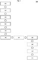
Fig. 1 : flow diagram showing the method steps for producing wire elements. -
Fig 2a, b : schematic illustration of a further coated wire with repeating units. -
Fig: 3a , b: schematic illustration showing repeating unit patterns. -
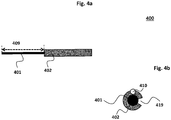
Fig. 4a . b: schematic illustration of a first coated wire. -
Fig. 5a , b: schematic illustration of marking effects in a first coated wire. -
Fig 6 : use of wire elements in a medical device. -
Fig. 1 shows the method steps for producing a plurality of wire elements according to the present invention. In step 101 a metal wire is provided. In anoptional step 102, the metal wire is subjected to an another quality control process. Instep 103, the metal wire is coated with a first layer to obtain a first coated wire, wherein the first layer has a first thickness. Instep 104, the first coated wire is subjected to a first quality control process. Any defects that are identified in the first coated wire are marked instep 105. - The first coated wire is then coated in
step 106 with a further layer to obtain a further coated wire. The further layer has a further thickness. In theoptional step 107, the further coated wire is subjected to a further quality control process. Instep 108, two or more repeating units are introduced along the further coated wire by reducing either the first thickness, the further thickness, or both. - In optional step 109, at least one repeating unit is subjected to an additional quality control process. In
optional step 110, repeating units with any additional defects identified are marked with a reject mark. The further coated wire is cut between at least one pair of neighbouring repeating units instep 111, thereby obtaining a plurality of wire elements. -
Fig. 2 shows a further coatedwire 200 that consists of ametal wire 201, afirst layer 202, and afurther layer 203.Fig. 2 further shows that thefirst layer 202 and thefurther layer 203 were removed in a repeating pattern, leading to the introduction of repeatingunits layers units unit 204. -
Repeating unit 204 has only themetal wire 201 and thefurther layer 203. During the production of the furthercoated wire 200, a first defect was detected in the first layer 202 (seestep 104 ofFig. 1 ) of a first coated wire. The first defect was marked (seestep 105 ofFig. 1 ) by removing alongitudinal portion 209 of thefirst layer 202 from repeatingunit 204. After removal of thefirst layer 202 inlongitudinal portion 209, the first coated wire was coated with thefurther layer 203. Repeatingunits wire 200. - Note that the process of removing the
first layer 202 and thefurther layer 203 in a repeating pattern was also applied to repeatingunit 204. However, the fact that thefirst layer 202 was removed leads to the repeating pattern not being visible inrepeating unit 204. -
Fig. 2 shows that the length of thelongitudinal portion 209 is equal to the length of repeatingunit 204. Although this is preferred, this is not a requirement. The length of thelongitudinal portion 209 can also be smaller or larger than the length of repeatingunit 204.Fig. 2 also shows that the position of thelongitudinal portion 209 coincides with the position of repeatingunit 204. Although this is preferred, this is also not a requirement. It is also possible that the position of a longitudinal portion only partially coincides with the position of a repeating unit. In this case, the longitudinal portion will partially extend over two, neighbouring repeating units. E.g., thelongitudinal portion 209 could have partially extended over repeatingunits -
Fig. 2 also shows that repeatingunit 206 has afurther defect 207 in thefurther layer 203. The repeatingunits further defect 207, repeatingunit 206 has been marked with areject mark 208. Due to the lack of thefirst layer 202, repeatingunit 204 did not pass the additional quality control process, and is therefore also marked with thereject mark 208. -
Fig. 2 shows that thereject mark 208 is applied by using layer ablation to remove thefirst layer 202 and thefurther layer 203 along a longitudinal portion. As a result, themetal wire 201 becomes visible in thereject mark 208. Thefirst layer 202 and thefurther layer 203 was also not completely removed around the circumference of the furthercoated wire 200. Rather thereject mark 208 has the form of a slit in the furthercoated wire 200. Furthermore, thereject mark 208 is detectable by an inspection means that comprises a camera and a computer with image recognition software. -
Figs. 3a, b show two exemplifying repeatingunits 300 with two different repeating patterns.Fig. 3a shows a repeatingunit 300 with seven sub-sections, 311 to 317. Every sub-section has a different number of layers compared to neighbouring sub-sections.Fig 3b shows a repeatingunit 300 with three sub-sections, 314 to 316. Every sub-section again has a different number of layers compared to neighbouring sub-sections. - In
Figs. 3a, b ,sub-sections metal wire 301 surrounded by afirst layer 302.Sub-section 314 consists of themetal wire 301 surrounded by thefirst layer 302, which in turn is surrounded by afurther layer 303.Sub-sections metal wire 312. - Note that a further coated wire will comprise at least two repeating units with the same repeating pattern. However, it is not necessary that all repeating units in a further coated wire have the same pattern. An example according to the present invention is a further coated wire that has two repeating units according to
Fig. 3a , as well as two repeating units according toFig. 3b . Further note thatFigs. 3a, b also serve as examples of wire elements, wherein the wire elements have the same length as the repeating units. -
Fig. 4 is a schematic illustration of a firstcoated wire 400.Fig. 4a shows the firstcoated wire 400 along its length. The first coated wire consists of ametal wire 401 and afirst layer 402. A first defect was detected in thefirst layer 402. The first defect was marked by removing thefirst layer 402 in alongitudinal portion 409. The first defect was located in thelongitudinal portion 409. -
Fig. 4b shows an alternative of marking the first defect.Fig. 4b shows a cross-section of the firstcoated wire 400. The cross-section is made perpendicular to the length of the firstcoated wire 400. Thefirst layer 402 has afirst defect 410. Similar toFig. 4a , thefirst layer 402 was removed in the longitudinal portion. However, in contrast toFig. 4a, Fig. 4b shows that thefirst layer 402 was not removed around a circumference of the firstcoated wire 400. Instead, thefirst layer 402 was only partially removed, leading to the cut-out 419. As a result, thefirst layer 402 is, to a first approximation, in the shape of a "C". -
Fig. 5a illustrates theprocess 500 for marking a first defect. Shown is a section of a first coated wire, where a cross-section has been made along a length of the section.Fig. 5a-I shows that the first coated wire consists of ametal wire 501 that is surrounded by afirst layer 502. Thefirst layer 502 has adefect 510 that has been identified in a first quality control process. -
Fig. 5a-II shows that thefirst layer 502 has been removed along alongitudinal portion 509. It can also be seen that the position of thefirst defect 510 coincided with the position of thelongitudinal portion 509. It can further be seen that thelongitudinal portion 509 was not removed around the circumference of the first coated wire (seeFig. 4b ). -
Fig. 5a-III shows that the first coated wire is coated with afurther layer 503 to obtain a further coated wire. Due to the removal of thefirst layer 502 in thelongitudinal portion 509, thefurther layer 503 does not have a uniform further thickness along a length of the further coated wire. Consequently, a further diameter is also not uniform the length of the further coated wire. -
Fig. 5a-IV shows that a repeatingunit 504 has been introduced along the further coated wire. In this example, the repeating unit has the pattern illustrated inFig. 3b . The repeatingunit 504 was subjected to an additional quality control process. A diameter of the repeating unit at a position D did not meet the product specifications. As a result, the repeatingunit 504 is marked with areject mark 508, as shown inFig. 5a-V . Thereject mark 508 is applied by removing thefurther layer 503 and thefirst layer 502 using laser ablation. -
Fig. 5b shows afurther process 500 for marking a first defect. The process is similar to that ofFig. 5a , with the difference that thefirst defect 510 is marked by removing thefirst layer 502 along alongitudinal portion 509, wherein the position of thelongitudinal portion 509 does not coincide with the position of thefirst defect 510. This is illustrated inFig. 5b-II . Nevertheless, when the repeatingunit 504 is subjected to the additional quality control process, a diameter of the repeatingunit 504 at the position D did not meet the product specifications. This is shown inFig. 5b-IV . As a result, the repeatingunit 504 is marked with areject mark 508, as shown inFig. 5b-V . Thereject mark 508 is applied by removing thefurther layer 503 and thefirst layer 502 using laser ablation. -
Fig. 6 shows the use of wire elements in amedical device 600. The medical device has amain body 661. Afirst wire element 662 is used in the circuits of themain body 661. Afurther wire element 663 is used as the electrode of themedical device 600. Themedical device 600 is used to measure the blood glucose levels of apatient 664. - Unless otherwise stated, all test methods are performed at a temperature of 25°C and a pressure of 101 325 Pa.
- Electrical conductivity is measured according to the standard ASTM B193 - 16.
- The dielectric strength of a coated wire is measured according to the standard DIN EN 60851-5:2009-05. Equipment used in the testing procedure can be commercially obtained from DSE Test Solutions A/S (Denmark).
- A diameter of a wire is measured according to the standard IEC 60851-2:2009.
- The number of defects in a first coated wire is measured according to the standard DIN EN 60851-5:2009-05. The number of defects in the further coated wire and the wire elements is measured using an inspection means.
- Continuous glucose monitors (CGM) that comprise wire elements are used to measure a standard sample. 100 CGM are used, in turn, to measure the glucose levels of a standard sample. Every CGM is used to make 200 measurements. The variance of the measurements is an indication of the measurement consistency. The smaller the variance, the more reliable a CGM is.
- The following measurement is repeated using 100 different wire elements, wherein every wire element comprises a metal wire, a first layer, and a further layer. The wire elements are used as a sensor element of a continuous glucose monitors (CGM). Before using the wire element to measure blood glucose levels, the dielectric strength of the wire element is measured. The blood glucose levels of a blood sample is then continuously measured for 24 hours. The dielectric strength of the wire element is then again measured. The difference in the dielectric strength prior to, and after measuring the blood glucose levels, is an indication of the life expectancy of a wire element. The smaller the aforementioned difference, the longer the life expectancy.
- Cross-sectional cuts are made through a wire element that consists of multiple sub-sections. A cross-section cut is made through every sub-section. The thickness of a layer in a cross-sectional cut is measured. The measurement is repeated for 1000 wire elements. A smaller variation in the thickness of a layer is preferred. The layer thickness variation for the further coated wire is measured using an inspection means.
- The variation in the diameter of the first coated wire, the further coated wire, and the wire elements are measured using an inspection means. The diameter is measured for every sub-section of a wire element.
- The invention is now illustrated by non-limiting examples.
- A metal wire with a diameter of 100 µm is provided. The metal wire comprises tantalum and platinum. The metal wire has an another length of 4000 m. The metal wire is coated with a first layer to obtain a first coated wire with a first length of 4000 m. The first layer consists of polyurethane, and has a first thickness of 25 µm.
- The first coated wire is subjected to a first quality control process in order to identify first defects. The first quality control process tests the dielectric strength of the first layer, as well as a first diameter of the first coated wire. The first quality control process also includes inspecting the first coated wire in order to identify bubbles or scratches in the first layer.
- When any first defects are identified in the first coated wire, the first layer is removed in a longitudinal portion using laser ablation. Every first defect is located in a longitudinal portion. The length of the longitudinal portions is 25 mm.
- The first coated wire is then coated with a further layer to obtain a further coated wire. A further length of the further coated wire is 4000 m. The further layer comprises polyurethane, silver, and silver chloride, and has a further thickness of 15 µm.
- In the next step, the first layer and the further layer are removed in a repeating pattern, thereby introducing repeating units. The first layer and the further layer are removed using laser ablation. All repeating units have the same pattern, with the average length of a repeating unit being 25 mm. Every repeating unit consists of three subsections. The first subsection consists of the metal wire, the first layer, and the further layer. The second subsection consists of the metal wire and the first layer. The third subsection consists of the metal wire.
- The further coated wire is cut between every pair of neighbouring repeating units. A plurality of wire elements with an average length of 25 mm is thereby obtained.
- This example is a comparison of two methods for producing a plurality of wire elements. The first method is according to the present invention, as described in Example 1. The second method is according to the prior art, as described in the "Background" section.
- A difference between the present invention and the prior art is that the latter teaches that the first coated wire should be cut when first defects are identified. This is in contrast to the present invention, wherein the first coated wire is not cut.
- Table 1 is a comparison of the two methods. For the comparison, the following average quantities were measured:
- production time: the time needed to produce 1000 m of the further coated wire or 1000 wire elements;
- number of defects: the number of defects in the first coated wire, the further coated wire, or the wire elements;
- production yield: the number of defect-free wire elements produced from a metal wire with a length of 1000 m;
- layer thickness variation: the variation in the thickness of a layer in the further coated wire or the wire elements.
- diameter variation: the variation in the diameter of the first coated wire, the further coated wire, or the wire elements.
- energy consumption: the energy needed in producing 1000 m of the further coated wire or 1000 wire elements;
- costs: the cost of producing 1000 m of the further coated wire or 1000 wire elements;
- set-up time: the time needed for setting up the production equipment used for producing the further coated wire and the wire elements;
- measurement reliability: the reliability of a measuring device using the wire elements;
- life expectancy: the life expectancy of the wire elements.
-
- 100
- Method for producing wire elements
- 101
- Provide metal wire
- 102
- Subject metal wire to another quality control process
- 103
- Coat metal wire with first layer to obtain first coated wire
- 104
- Subject first coated wire to first quality control process
- 105
- Mark first defects
- 106
- Coat first coated wire with further layer to obtain further coated wire
- 107
- Subject further coated wire to further quality control process
- 108
- Introduce repeating units
- 109
- Subject repeating units to additional quality control process
- 110
- Apply reject mark to defective repeating units
- 111
- Cut further coated wire to obtain wire elements
- 200
- Further coated wire
- 201
- Metal wire
- 202
- First layer
- 203
- Further layer
- 204
- Defective repeating unit
- 205
- Repeating unit
- 206
- Defective repeating unit
- 207
- Further defect
- 208
- Reject mark
- 209
- Longitudinal portion
- 300
- Repeating unit
- 301
- Metal wire
- 302
- First layer
- 303
- Further layer
- 311 - 317
- Sub-sections
- 400
- First coated wire
- 401
- Metal wire
- 402
- First layer
- 409
- Longitudinal portion
- 410
- First defect
- 419
- Cut-out
- 500
- Process for marking first defect
- 501
- Metal wire
- 502
- First layer
- 503
- Further layer
- 508
- Reject mark
- 509
- Longitudinal portion
- 510
- First defect
- 600
- Medical device
- 661
- Main body
- 662
- First wire element
- 663
- Further wire element / electrode
- 664
- Patient
| Metric | Present invention | Prior art |
| Production time (h) | ||
| Further coated wire | Lower | Higher |
| Wire elements | Lower | Higher |
| Number of defects | ||
| First coated wire | Equal | Equal |
| Further coated wire | Lower | Higher |
| Wire elements | Lower | Higher |
| Production yield | Higher | Lower |
| Layer thickness variation | Lower | Higher |
| Further coated wire | Lower | Higher |
| Wire elements | Lower | Higher |
| Diameter variation | ||
| First coated wire | Equal | Equal |
| Further coated wire | Lower | Higher |
| Wire elements | Lower | Higher |
| Energy consumption | ||
| Further coated wire | Lower | Higher |
| Wire elements | Lower | Higher |
| Costs (€) | ||
| Further coated wire | Lower | Higher |
| Wire elements | Lower | Higher |
| Set-up time (d:h) | Lower | Higher |
| Measurement reliability | Higher | Lower |
| Life expectancy | Higher | Lower |
Claims (15)
- A method for producing a plurality of wire elements, comprising the steps ofa. providing a metal wire, wherein the metal wire comprises an inner metal core layer;b. coating the metal wire with a first layer to obtain a first coated wire, wherein the first layer has a first thickness;c. subjecting the first coated wire to a first quality control process;d. marking any first defects identified in the first quality control process;e. coating the first coated wire with a further layer to obtain a further coated wire, wherein the further layer has a further thickness;f. introducing two or more repeating units along the further coated wire by reducing the first thickness, the further thickness, or both;g. cutting the further coated wire between at least one pair of neighbouring repeating units to obtain a plurality of wire elements;
wherein
prior to cutting the further coated wire in step g. to obtain the plurality of wire elements, a first length of the first coated wire is less than 10 % longer than a further length of the further coated wire. - The method according to claim 1, wherein, before the two or more repeating units are introduced, the following steps are performed:a. subjecting the further coated wire to a further quality control process;b. identifying further defects;c. marking the further defects.
- The method according to any of the preceding claims, wherein, after the two or more repeating units have been introduced, the following steps are performed:a. subjecting the repeating units to an additional quality control process;b. identifying additional defects;c. marking the repeating units that comprise at least one additional defect with a reject mark.
- The method according to any of the preceding claims, wherein, prior to coating the metal wire with the first layer, the following steps are preformed:a. subjecting the metal wire to an another quality control process;b. identifying another defects;c. marking the another defects.
- The method according to any of the preceding claims, wherein laser ablation is used for at least one or all of the following:a. marking the first defects, the further defects, or both;b. reducing the first thickness, the further thickness, or both;c. applying the reject mark.
- The method according to any of the preceding claims, wherein the repeating units has a length in the range of 1 mm to 110 mm.
- The method according to any of the preceding claims, wherein the first quality control process comprises at least one or all of the following:a. inspecting the first coated wire;b. testing at least one physical property of the first coated wire;c. testing at least one dimensional property of the first coated wire.
- The method according to any of the claims 2 to 7, wherein the further quality control process comprises at least one or all of the following:a. inspecting the further coated wire;b. testing at least one dimensional property of the further coated wire.
- The method according to any of the claims 3 to 8, wherein the additional quality control process comprises at least one or all of the following:a. inspecting at least one repeating units;b. testing the number of subsections in at least one repeating units;c. testing at least one dimensional property of at least one repeating units.
- The method according to any of the claims 4 to 9, wherein the another quality control process comprises at least one or all of the following:a. inspecting the metal wire;b. testing at least one physical property of the metal wire.c. testing at least one dimensional property of the metal wire.
- The method according to any of the preceding claims, wherein the first length of the first coated wire is in the range of 1000 m to 6000 m.
- The method according to any of the preceding claims, wherein the time required for performing steps b. through f. in claim 1 is in the range of 1 m/min to 900 m/min.
- The method according to any of the preceding claims, wherein at least one or all of the following is true:a. at least 80 % of an another length of the metal wire is coated with the first layer;b. at least 80 % of the first length of the first coated wire is coated with the further layer.
- A wire element obtainable by a method according to any of the claims 1 to 13.
- A use of a wire element according to claim 14 as a sensor.
Priority Applications (2)
| Application Number | Priority Date | Filing Date | Title |
|---|---|---|---|
| EP20166510.6A EP3885859A1 (en) | 2020-03-27 | 2020-03-27 | Increasing production yield of coated wire elements |
| US17/214,052 US11887754B2 (en) | 2020-03-27 | 2021-03-26 | Increasing production yield of coated wire elements |
Applications Claiming Priority (1)
| Application Number | Priority Date | Filing Date | Title |
|---|---|---|---|
| EP20166510.6A EP3885859A1 (en) | 2020-03-27 | 2020-03-27 | Increasing production yield of coated wire elements |
Publications (1)
| Publication Number | Publication Date |
|---|---|
| EP3885859A1 true EP3885859A1 (en) | 2021-09-29 |
Family
ID=70475943
Family Applications (1)
| Application Number | Title | Priority Date | Filing Date |
|---|---|---|---|
| EP20166510.6A Pending EP3885859A1 (en) | 2020-03-27 | 2020-03-27 | Increasing production yield of coated wire elements |
Country Status (2)
| Country | Link |
|---|---|
| US (1) | US11887754B2 (en) |
| EP (1) | EP3885859A1 (en) |
Citations (4)
| Publication number | Priority date | Publication date | Assignee | Title |
|---|---|---|---|---|
| GB2124121A (en) * | 1982-06-18 | 1984-02-15 | Sumitomo Metal Ind | Dry type continuous wire drawing process and machine |
| US20090171494A1 (en) * | 2005-06-17 | 2009-07-02 | Markus Wachter | Concept for monitoring the manufacture of objects consisting of multiple material layers |
| JP2014100323A (en) * | 2012-11-20 | 2014-06-05 | Terumo Corp | Catheter tube manufacturing method |
| US20170252867A1 (en) * | 2014-09-12 | 2017-09-07 | Scherdel Innotec Forschungs-und Entwicklungs GmbH | Device and method for producing a spring wire, device and method for making a spring wire, device and method for producing springs from a spring wire, and spring wire |
-
2020
- 2020-03-27 EP EP20166510.6A patent/EP3885859A1/en active Pending
-
2021
- 2021-03-26 US US17/214,052 patent/US11887754B2/en active Active
Patent Citations (4)
| Publication number | Priority date | Publication date | Assignee | Title |
|---|---|---|---|---|
| GB2124121A (en) * | 1982-06-18 | 1984-02-15 | Sumitomo Metal Ind | Dry type continuous wire drawing process and machine |
| US20090171494A1 (en) * | 2005-06-17 | 2009-07-02 | Markus Wachter | Concept for monitoring the manufacture of objects consisting of multiple material layers |
| JP2014100323A (en) * | 2012-11-20 | 2014-06-05 | Terumo Corp | Catheter tube manufacturing method |
| US20170252867A1 (en) * | 2014-09-12 | 2017-09-07 | Scherdel Innotec Forschungs-und Entwicklungs GmbH | Device and method for producing a spring wire, device and method for making a spring wire, device and method for producing springs from a spring wire, and spring wire |
Non-Patent Citations (1)
| Title |
|---|
| DEHNEADLERSCHWESINGER: "Lehrbuch Mikrosystemtechnik: Anwendungen, Grundlagen, Materialien und Herstellung von Mikrosystemen", 2008 |
Also Published As
| Publication number | Publication date |
|---|---|
| US20210304923A1 (en) | 2021-09-30 |
| US11887754B2 (en) | 2024-01-30 |
Similar Documents
| Publication | Publication Date | Title |
|---|---|---|
| EP1772728B1 (en) | Method and system for testing electrochemical sensors | |
| EP2124044B1 (en) | Method for calculating and evaluating eddy current displays, in particular cracks, in a test object made from a conductive material | |
| JP6908462B2 (en) | Insulated wire inspection method | |
| US11887754B2 (en) | Increasing production yield of coated wire elements | |
| CN120685988A (en) | A method and system for diagnosing and monitoring cable aging | |
| CN113053588A (en) | Method for producing insulated wire, method for inspecting insulated wire, and apparatus for producing insulated wire | |
| KR102827172B1 (en) | Polymer-coated wires | |
| JP2011507188A (en) | Electrode tuning method and apparatus for laminated heater structure | |
| JP2007155368A (en) | Flaw detection method of conductive coating film and flaw detector used therefor | |
| CN104037107A (en) | Failure analysis method for through hole chain structure | |
| CN114025488A (en) | FPCB production process based on electroplating hole conduction performance detection | |
| JP5487579B2 (en) | Silicon wafer evaluation method and manufacturing method | |
| CN119291470A (en) | A PCB board aging test method | |
| JP2006317412A (en) | Probe needle with insulating coating and method for manufacturing the same | |
| Della Giovanna et al. | AI Algorithms for Post-Processing and Analysis of Partial Discharge Signals During Ageing of Insulation | |
| JP6893815B2 (en) | Manufacturing method of insulated wire | |
| JP7698809B1 (en) | Insulated wire manufacturing method, defect detection method, and insulated wire manufacturing system | |
| DE69803660T2 (en) | ELKETROSTATIC ADHESIVITY TESTER FOR THIN-LAYER LADDER | |
| JP2018170260A (en) | Insulated wire manufacturing method | |
| CN104865510B (en) | The method of inspection of air reactor inner conductor Abnormal Insulation and mass defect | |
| WO2019179984A1 (en) | Coupon and method for checking a printed circuit board | |
| WO2010045936A2 (en) | Eddy current sensor and method for determining material characteristics modified by thermal influences, in a component to be examined, by means of said sensor | |
| US8879274B2 (en) | Method of manufacturing an electrical component | |
| JP7774668B2 (en) | Processing equipment and method for manufacturing electrodes for battery cells | |
| US9151730B2 (en) | Method for determining the electrochemical characteristic of a test strip |
Legal Events
| Date | Code | Title | Description |
|---|---|---|---|
| PUAI | Public reference made under article 153(3) epc to a published international application that has entered the european phase |
Free format text: ORIGINAL CODE: 0009012 |
|
| STAA | Information on the status of an ep patent application or granted ep patent |
Free format text: STATUS: REQUEST FOR EXAMINATION WAS MADE |
|
| 17P | Request for examination filed |
Effective date: 20200327 |
|
| AK | Designated contracting states |
Kind code of ref document: A1 Designated state(s): AL AT BE BG CH CY CZ DE DK EE ES FI FR GB GR HR HU IE IS IT LI LT LU LV MC MK MT NL NO PL PT RO RS SE SI SK SM TR |
|
| RAP3 | Party data changed (applicant data changed or rights of an application transferred) |
Owner name: HERAEUS DEUTSCHLAND GMBH & CO. KG |
|
| RAP1 | Party data changed (applicant data changed or rights of an application transferred) |
Owner name: HERAEUS MEDEVIO GMBH & CO. KG |
|
| STAA | Information on the status of an ep patent application or granted ep patent |
Free format text: STATUS: EXAMINATION IS IN PROGRESS |
|
| 17Q | First examination report despatched |
Effective date: 20231220 |
|
| GRAP | Despatch of communication of intention to grant a patent |
Free format text: ORIGINAL CODE: EPIDOSNIGR1 |
|
| STAA | Information on the status of an ep patent application or granted ep patent |
Free format text: STATUS: GRANT OF PATENT IS INTENDED |
|
| INTG | Intention to grant announced |
Effective date: 20251023 |
|
| GRAJ | Information related to disapproval of communication of intention to grant by the applicant or resumption of examination proceedings by the epo deleted |
Free format text: ORIGINAL CODE: EPIDOSDIGR1 |
|
| STAA | Information on the status of an ep patent application or granted ep patent |
Free format text: STATUS: EXAMINATION IS IN PROGRESS |
|
| GRAP | Despatch of communication of intention to grant a patent |
Free format text: ORIGINAL CODE: EPIDOSNIGR1 |
|
| STAA | Information on the status of an ep patent application or granted ep patent |
Free format text: STATUS: GRANT OF PATENT IS INTENDED |
|
| INTC | Intention to grant announced (deleted) | ||
| INTG | Intention to grant announced |
Effective date: 20251222 |