JP2014100323A - Catheter tube manufacturing method - Google Patents
Catheter tube manufacturing method Download PDFInfo
- Publication number
- JP2014100323A JP2014100323A JP2012254616A JP2012254616A JP2014100323A JP 2014100323 A JP2014100323 A JP 2014100323A JP 2012254616 A JP2012254616 A JP 2012254616A JP 2012254616 A JP2012254616 A JP 2012254616A JP 2014100323 A JP2014100323 A JP 2014100323A
- Authority
- JP
- Japan
- Prior art keywords
- core wire
- layer covering
- diameter portion
- inner layer
- catheter tube
- Prior art date
- Legal status (The legal status is an assumption and is not a legal conclusion. Google has not performed a legal analysis and makes no representation as to the accuracy of the status listed.)
- Pending
Links
Images


Abstract
Description
本発明は、血管等の管腔内や体腔内で使用されるカテーテルに用いられるカテーテル用チューブの製造方法に関する。 The present invention relates to a method for manufacturing a catheter tube used for a catheter used in a lumen such as a blood vessel or a body cavity.
近年、外科的侵襲が非常に低いという理由から、カテーテルを用いた血管等の管腔内や体腔内の治療が盛んに行われている。例えば、体内の複雑に分岐した血管へ選択的に導入して使用されるカテーテルは、一般的に、血管へあらかじめ導入されるガイドワイヤーに沿って選択的に押し込まれて、治療用の薬剤や診断用の造影剤等を手元側(基端側)から先端側へ流通させる。このため、カテーテルを構成する長尺なカテーテル用チューブは、手元側の内外径を大きくすることで、剛性を高めて押込み性(プッシャビリティー)を充分に持たせつつ薬剤や造影剤の注入特性を確保し、先端側の内外径を基端側よりも細くし、柔軟にすることで末梢血管への到達性やガイドワイヤーへの追従性を高めている。 In recent years, treatment in a lumen such as a blood vessel or a body cavity using a catheter has been actively performed for the reason that surgical invasion is very low. For example, catheters that are selectively introduced into complex branched blood vessels in the body are typically selectively pushed along a guide wire that is pre-introduced into the blood vessel to provide therapeutic drugs and diagnostics. The contrast agent for use is distributed from the proximal side (base end side) to the distal end side. For this reason, the long catheter tube that constitutes the catheter increases the inner and outer diameters on the proximal side, so that the injection characteristics of drugs and contrast agents are enhanced while maintaining sufficient rigidity and pushability. And the inner and outer diameters on the distal end side are made thinner than the proximal end side, making it flexible, thereby improving the reachability to the peripheral blood vessels and the followability to the guide wire.
このようなカテーテル用チューブの製造方法として、例えば特許文献1には、外径の異なる太径部と細径部が所定の間隔で連続してなる芯線上に熱可塑性樹脂を被覆成形して内層被覆体を形成し、この内層被覆体上に金属線や樹脂繊維等の補強体を形成し、補強体の上に熱可塑性樹脂からなる外層被覆体を押出成形により被覆して、複数のカテーテル用チューブを同一の芯線上に連続体として形成した後、連続体を各々のカテーテル用チューブ毎に芯線とともに切断し、芯線を引き抜いて除去してカテーテル用チューブを製造する方法が記載されている。
As a method for producing such a catheter tube, for example,
しかしながら、上述した特許文献1に記載の方法では、カテーテル用チューブの先端側および基端側における外径および内径の変化を、芯線に太径部および細径部を設けることで設定しており、カテーテル用チューブに適用可能な形状が制限される。
However, in the method described in
本発明は、上述した課題を解決するためになされたものであり、複数のカテーテル用チューブを同一の芯線を用いて連続的に製造しつつ、製造されるカテーテル用チューブの形状をより自在に設定可能なカテーテル用チューブの製造方法を提供することを目的とする。 The present invention has been made in order to solve the above-described problems, and while continuously manufacturing a plurality of catheter tubes using the same core wire, the shape of the manufactured catheter tube can be set more freely. An object of the present invention is to provide a method for manufacturing a catheter tube.
上記目的を達成するカテーテル用チューブの製造方法は、芯線上に樹脂を被覆して内層被覆体を形成する内層被覆体形成工程と、前記内層被覆体形成工程よりも後に、熱可塑性樹脂を押出成形により前記芯線の軸線方向へ厚さを変化させつつ前記内層被覆体よりも径方向外側に被覆して外層被覆体を形成する外層被覆体形成工程と、前記外層被覆体形成工程よりも後に前記芯線上に前記内層被覆体および外層被覆体を備えて得られる管状連続体を、所定の位置で切断して複数の単体チューブを切り出す切断工程と、前記単体チューブから前記芯線を除去する芯線除去工程と、を有するカテーテル用チューブの製造方法である。 A method for manufacturing a catheter tube that achieves the above object includes an inner layer covering forming step of forming an inner layer covering by coating a resin on a core wire, and extruding a thermoplastic resin after the inner layer covering forming step. The outer layer covering body forming step of forming an outer layer covering body by coating the outer side of the inner layer covering body in the radial direction while changing the thickness in the axial direction of the core wire, and the core after the outer layer covering body forming step A cutting step of cutting a tubular continuous body obtained by providing the inner layer covering body and the outer layer covering body on a line at a predetermined position to cut out a plurality of single tubes; and a core wire removing step of removing the core wires from the single tubes; , A method for producing a catheter tube.
上記のように構成したカテーテル用チューブの製造方法は、内層被覆体よりも径方向外側に、押出成形によって前記芯線の軸線方向へ厚さを変化させつつ外層被覆体を被覆するため、複数層からなるカテーテル用チューブの形状をより自在に設定可能となる。 The method for manufacturing a catheter tube configured as described above covers the outer layer covering body while changing the thickness in the axial direction of the core wire by extrusion molding on the outer side in the radial direction from the inner layer covering body. The shape of the catheter tube can be set more freely.
前記芯線は、外径の異なる太径部および細径部が予め所定の間隔で連続して形成されるようにすれば、先端側と基端側で径の異なるカテーテル用チューブを、連続的に連なる管状連続体を用いて効率よく製造できる。 The core wire is formed by continuously forming catheter tubes having different diameters at the distal end side and the proximal end side by continuously forming a large diameter portion and a small diameter portion having different outer diameters at predetermined intervals. It can manufacture efficiently using a continuous tubular continuous body.
前記切断工程において、前記管状連続体を前記太径部および細径部の所定の位置で切断して複数の前記単体チューブを切り出し、芯線除去工程は、前記切断工程よりも後に実施されるようにすれば、芯線に太径部および細径部が形成されることで切断前は芯線の除去が困難であっても、切断工程の後に芯線を容易に除去できる。 In the cutting step, the tubular continuous body is cut at predetermined positions of the large diameter portion and the small diameter portion to cut out the plurality of single tubes, and the core wire removing step is performed after the cutting step. Then, even if it is difficult to remove the core wire before cutting because the large diameter portion and the small diameter portion are formed on the core wire, the core wire can be easily removed after the cutting step.
前記外層被覆体形成工程において、前記太径部から細径部へ向かう方向へ厚さが減少するように前記外層被覆体を形成するようにすれば、製造されるカテーテル用チューブの基端側となる基端部から生体内に挿入される先端部へ向かって、外層被覆体の厚さを減少させることができ、カテーテル用チューブの剛性が軸線に沿って滑らかかつ傾斜的に変化し、局所的な曲がりが抑制されて、押込み性および耐キンク性に優れたカテーテル用チューブを製造できる。 In the outer layer covering body forming step, if the outer layer covering body is formed so that the thickness decreases in the direction from the large diameter portion toward the small diameter portion, the proximal end side of the manufactured catheter tube and The thickness of the outer covering can be reduced from the proximal end portion to the distal end portion inserted into the living body, and the rigidity of the catheter tube changes smoothly and in an inclined manner along the axis, and is locally Therefore, it is possible to manufacture a catheter tube excellent in indentability and kink resistance.
前記芯線は、前記太径部および細径部の間に細径部から太径部へ向かって外径が拡がる移行部を有するようにすれば、製造されるカテーテル用チューブの剛性が軸線に沿って滑らかかつ傾斜的に変化し、局所的な曲がりが抑制されて、押込み性および耐キンク性に優れたカテーテル用チューブを製造できる。 If the core wire has a transition portion between which the outer diameter expands from the small diameter portion toward the large diameter portion between the large diameter portion and the small diameter portion, the rigidity of the catheter tube to be manufactured is along the axis. Therefore, it is possible to manufacture a catheter tube having excellent pushability and kink resistance.
前記芯線の軸線に沿う断面における前記移行部の外周面の形状が曲線を有して形成されるようにすれば、製造されるカテーテル用チューブの剛性が軸線に沿って滑らかかつ傾斜的に変化し、局所的な曲がりが抑制されて、押込み性および耐キンク性に優れたカテーテル用チューブを製造できる。 If the shape of the outer peripheral surface of the transition portion in the cross section along the axis of the core wire is formed with a curve, the rigidity of the manufactured catheter tube changes smoothly and inclined along the axis. In addition, it is possible to manufacture a catheter tube that is suppressed in local bending and excellent in pushability and kink resistance.
前記内層被覆体形成工程よりも後、前記内層被覆体の径方向外側に、線材からなる補強体を形成する補強体形成工程をさらに有するようにすれば、製造されるカテーテル用チューブを部位に応じて補強でき、押込み性および耐キンク性を向上させることができる。 If the catheter further includes a reinforcing body forming step for forming a reinforcing body made of a wire on the radially outer side of the inner layer covering body after the inner layer covering body forming step, the manufactured catheter tube can be made according to the site. Can be reinforced, and indentability and kink resistance can be improved.
以下、図面を参照して、本発明の実施の形態を説明する。なお、図面の寸法比率は、説明の都合上、誇張されて実際の比率とは異なる場合がある。 Embodiments of the present invention will be described below with reference to the drawings. In addition, the dimension ratio of drawing is exaggerated on account of description, and may differ from an actual ratio.
本実施形態に係るカテーテル用チューブの製造方法により製造されるカテーテル用チューブ10は、図1に示すように、血管、胆管、気管、食道、尿道、またはその他の生体管腔内や体腔内に挿入されて治療や診断等を行うためのカテーテル1に用いられる。カテーテル1は、長尺なカテーテル用チューブ10と、カテーテル用チューブ10の基端に連結されるハブ20と、カテーテル用チューブ10およびハブ20の連結部位に設けられる耐キンクプロテクタ30と、を有している。なお、本明細書では、管腔に挿入する側を「先端」若しくは「先端側」、操作する手元側を「基端」若しくは「基端側」と称することとする。
A
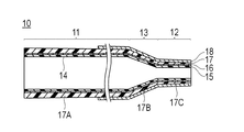
カテーテル用チューブ10は、図1,2に示すように、可撓性を有する管状の部材であり、基端側に位置するチューブ基端部11と、チューブ基端部11より小さい外径および内径を有するチューブ先端部12と、チューブ基端部11およびチューブ先端部12の間で外径および内径が軸線方向に向かって徐々に変化するチューブ移行部13と、を有している。カテーテル用チューブ10は、基端から先端にかけて内部にルーメン14が形成されている。ルーメン14は、例えばガイドワイヤー用ルーメンとして機能するものであり、カテーテル1の生体管腔内への挿入時には、ガイドワイヤーが挿通される。また、ルーメン14は、薬液や塞栓物質、造影剤等の通路として用いることもできる。
As shown in FIGS. 1 and 2, the
カテーテル用チューブ10は、複数の層で構成されており、最内層を構成する内層15と、内層15の外側に形成される補強層16と、内層15および補強層16の外側に形成される外層17と、外層17の外側に被覆される親水層18とを備えている。外層17は、チューブ基端部11に位置する外層基端部17Aと、チューブ移行部13に位置する外層移行部17Bと、チューブ先端部12に位置する外層先端部17Cとを備えている。外層基端部17A、外層移行部17Bおよび外層先端部17Cは、いずれも、基端側から先端側へ向かう方向へ厚さが減少するように形成される。なお、外層基端部17A、外層移行部17Bおよび外層先端部17Cの一部でのみ、基端側から先端側へ向かう方向へ厚さが減少するように形成されてもよいが、少なくとも外層基端部17Aにおいて、基端側から先端側へ向かう方向へ厚さが減少することが好ましい。内層15、補強層16、外層17および親水層18の構成および材料は、後述する製造方法にて詳細に説明する。
The
ハブ20は、カテーテル用チューブ10の基端部が接着剤、熱融着または止具(図示せず)等により液密に固着されている。ハブ20は、ルーメン14内へのガイドワイヤーの挿入口、ルーメン14内への薬液や塞栓物質、造影剤等の注入口等として機能し、また、カテーテル1を操作する際の把持部としても機能する。ハブ20の材料は、特に限定されないが、例えば、ポリカーボネート、ポリアミド、ポリサルホン、ポリアリレート、メタクリレート−ブチレン−スチレン共重合体等の熱可塑性樹脂が好適に使用できる。
In the
耐キンクプロテクタ30は、カテーテル用チューブ10の周囲を囲むように設けられる弾性材料からなり、カテーテル用チューブ10とハブ20の連結部位におけるカテーテル用チューブ10のキンクを抑制する。耐キンクプロテクタ30の材料は、例えば、天然ゴム、シリコーン樹脂等が好適に使用できる。
The
次に、本実施形態に係るカテーテル用チューブの製造方法について説明する。カテーテル用チューブ10は、長尺な芯線40を準備する芯線準備工程(図3(A))と、芯線40上に内層被覆体51を形成する内層被覆体形成工程(図3(B))と、内層被覆体51上に補強体52を形成する補強体形成工程(図3(C))と、補強体52および内層被覆体51を一体的に被覆して外層被覆体53を形成する外層被覆体形成工程(図3(D))と、親水性被覆体54を被覆する親水性被覆体形成工程(図3(E))と、芯線40上に得られる管状連続体60を芯線40の所定の位置で切断して単体チューブ61を切り出す切断工程(図3(F))と、芯線40を延伸させる芯線延伸工程(図3(G))と、各単体チューブ61から芯線40を除去する芯線除去工程(図3(H))と、を有している。芯線40上に形成される内層被覆体51、補強体52、外層被覆体53および親水性被覆体54は、最終的に、カテーテル用チューブ10の内層15、補強層16、外層17および親水層18となる。
Next, a method for manufacturing a catheter tube according to this embodiment will be described. The
芯線準備工程は、図3(A)に示すように、芯線40を切削、研磨、研削、鍛造、溶接、割りダイスを用いた引抜き延伸等の機械的加工、または、エッチング等の化学的加工により、太径部41、細径部42および移行部43を有するように加工する工程、または、上記のような加工が施された芯線40を購入等により準備する工程である。
As shown in FIG. 3 (A), the core wire preparation step is performed by mechanical processing such as drawing, drawing, or the like using a cutting die, cutting, polishing, grinding, forging, welding, split die, or chemical processing such as etching. , A step of processing to have the large-
芯線準備工程において準備される芯線40は、所定の外径を有する太径部41と、太径部41より小さい外径を有する細径部42と、太径部41および細径部42の間で外径が芯線40の軸線方向に向かって徐々に変化する移行部43と、が複数並んで構成されている。細径部42の外径D2に対する太径部41の外径D1の比率(D1/D2)は、1.00を超えて1.31以下であることが好ましく、より好ましくは1.30以下であり、さらに好ましくは1.22以下である。比率(D1/D2)は1より大きい。比率(D1/D2)が1.31以下であることで、芯線延伸工程において細径部42のみならず太径部41も良好に延伸させ、細径部42のみの細りを抑制して、芯線除去工程において芯線40を良好に除去することが可能となり、実使用に耐え得るカテーテル用チューブ10を製造可能となる。比率(D1/D2)が1.22以下であれば、細径部42のみの細りがより確実に抑制されて、芯線除去工程において芯線40をより確実に除去することが可能となり、より良好なカテーテル用チューブ10を製造可能となる。一例として、太径部41の長さL1は1800mm、細径部42の長さL2は150mm、移行部43の長さL3は50mm、太径部41の外径D1は0.55〜0.6mm、細径部42の外径D2は0.45〜0.50mmとすることができるが、寸法はこれに限定されない。
The
芯線40の材料は、銅線、ステンレス軟線等延伸できる金属、または、ポリアミド(PA)等の樹脂ストランド等を適用でき、その断面は円形に限定されず、楕円、半円、多角形等の任意の形状とすることができる。
The material of the
芯線準備工程の後には、図3(B)に示すように、芯線40上に内層被覆体51を形成する(内層被覆体形成工程)。内層被覆体51の材料は、熱可塑性樹脂や熱硬化性樹脂等を適用でき、フッ素系樹脂、高密度ポリエチレン(HDPE)等の低摩擦材料等が好ましい。 After the core wire preparation step, as shown in FIG. 3 (B), an inner layer covering 51 is formed on the core wire 40 (inner layer covering forming step). As the material of the inner layer covering 51, a thermoplastic resin, a thermosetting resin, or the like can be applied, and a low friction material such as a fluorine-based resin or high-density polyethylene (HDPE) is preferable.
内層被覆体51には、X線不透過物質を混合してもよい。なお、内層被覆体51をフッ素系樹脂等の低摩摩擦材料で形成する場合には、外側に他の材料を被覆できるように、内層被覆体51の外側表面に、ケミカルエッチング等により粗面化処理を施すことが好ましい。 The inner layer covering 51 may be mixed with a radiopaque material. When the inner layer covering 51 is formed of a low friction material such as a fluororesin, the outer surface of the inner layer covering 51 is roughened by chemical etching or the like so that other materials can be covered on the outer side. It is preferable to perform the treatment.
内層被覆体51の材料に熱可塑性樹脂を用いる場合には、押出成形機にて所定の成形温度(ダイス温度)で所定の引き取り速度で押出成形することができる。これにより、略同一肉厚の押出成形体(内層被覆体51)を得ることができる。一例として、太径部41に対応する部位の内層被覆体51の外径を0.57〜0.76mm、細径部42に対応する部位の内層被覆体51の外径を0.47〜0.53mmとすることができるが、寸法はこれに限定されない。なお、引き取り速度を調整することで、部位に応じて肉厚を変化させることもできる。
When a thermoplastic resin is used as the material of the inner layer covering 51, it can be extruded at a predetermined take-up speed at a predetermined molding temperature (die temperature) with an extruder. Thereby, the extrusion molding (inner layer covering 51) of substantially the same thickness can be obtained. As an example, the outer diameter of the inner layer covering 51 in the portion corresponding to the
押出成形法を概説すれば、図4に示すような一般的な押出成形機100を用いて、芯材W(ここでは、芯線40)上に熱可塑性樹脂の層(ここでは、内層被覆体51)を成形する。押出成形機100は、加熱溶融した材料を押し出す押出機101と、押出機101から押し出された樹脂を押出口102から押し出す金型103と、金型103を貫通して押出口102の中心に位置する芯材Wを引き取る引取機105と、芯材Wが巻回されて保持されるとともに金型103へ芯材Wを供給する供給ロール106と、押出成形が完了した芯材Wを回収する回収ロール107と、を備えている。芯材W上に材料を押出成形する際には、押出機101により加熱溶融した材料を金型103に供給して、供給ロール106から送り出されて押出口102に位置する芯材Wを引取機105により引き取りつつ押出口102から芯材W上に材料を連続的に供給して、芯材W上に材料を被覆させる。材料が被覆された芯材Wは、被覆された材料が固化した後に回収ロール107に巻回されて回収される。引取機105による引き取り速度を変更することで、押し出される成形品の外径を任意に変更することができる。また、内層被覆体51の押出成形において、樹脂としてフッ素系樹脂(PTFEなど)を用いる場合、フッ素系潤滑剤を助剤として樹脂粉末と混合したものを押し出しすることができる。
An outline of the extrusion molding method is as follows. Using a general
なお、内層被覆体形成工程では、内層被覆体51を押出成形により成形するのではなしに、ディップ成形によって成形してもよい。ディップ成形による方法を概説すれば、まず、図5に示すような容器200内に、材料である樹脂を溶剤に溶解した溶液Rまたは希釈剤中に分散させた分散液Rを収容し、容器200の底に設けられて液密性を維持しつつ芯材W(ここでは、芯線40)を挿通可能である柔軟な弁体201を介して、芯材Wが巻回されて保持される供給ロール202から芯材Wを供給し、芯材Wを下方から容器200内に挿入する。そして、容器200内で溶液Rまたは分散液Rに芯材Wをディッピング(浸漬)させた後に、容器200の上方へ引き抜く。これにより、芯材Wの外周面に溶液Rまたは分散液Rを付着させ、芯材Wに付着させた溶液Rまたは分散液Rを熱風やヒータ等によって加熱して乾燥させ、フッ素系樹脂等の分散液Rを用いる場合にはさらに焼結させて、内層被覆体51を形成する。材料が被覆された芯材Wは、被覆された材料が固化した後に回収ロール203に巻回されて回収される。溶剤や希釈剤には、通常用いられているものを適用することができる。容器200からの引き上げ速度を変更することで、芯材Wに付着される溶液Rまたは分散液Rの膜厚を任意に変更し、内層被覆体51の厚さを任意に変更することができる。膜厚は、溶液Rまたは分散液Rの密度、表面張力、粘度、重力および引き上げ速度が相互に作用して決定され、容器200からの引き上げ速度を遅くすると、芯材Wに付着される溶液Rまたは分散液Rの膜厚を増加させることができ、引き上げ速度を速くすると、芯材Wに付着される溶液Rまたは分散液Rの膜厚を減少させることができる。例えば、太径部41よりも細径部42に対応する部位の膜厚を薄くして、移行部43に対応する部位の膜厚を、漸次的に変化させることもできる。
In the inner layer covering body forming step, the inner
また、溶液Rまたは分散液Rの粘度が高いと、被覆される厚さが不均一となりやすいため、被覆される膜厚が均一となる程度に粘度を低く設定し、ディップ成形を複数回繰り返し行うことで、被覆させる膜厚を徐々に増加させて、被覆厚さを高精度に制御することができる。ディップ成形を繰り返し行う際には、材料が被覆された芯材Wが回収された回収ロール203を、容器200の下方へ移動させて供給ロール202とし、再びディップ成形を行うことができる。ディップ成形を繰り返し行う際には、一回毎に、溶液Rまたは分散液Rを熱風やヒータ等によって加熱して乾燥および焼結させることが好ましい。
Also, if the viscosity of the solution R or dispersion R is high, the coating thickness tends to be non-uniform, so the viscosity is set low enough to make the coating film thickness uniform, and dip molding is repeated multiple times. Thus, the coating thickness can be gradually increased, and the coating thickness can be controlled with high accuracy. When the dip molding is repeatedly performed, the
また、ディップ成形を複数回繰り返し行う際には、芯線40の同じ方向へ引き上げてディップ成形するのではなしに、少なくとも1回は逆方向へ引き上げてディップ成形することが好ましく、より好ましくは、1回ずつ方向を変えながらディップ成形することが好ましい。少なくとも1回は逆方向からディップ成形することで、引き上げ方向に依存する膜厚の偏りを抑制して膜厚を均一化でき、1回ずつ方向を変えながらディップ成形することで、引き上げ方向による膜厚の偏りを最大限に抑制して、膜厚をより均一とすることができる。特に、外径が変化する芯線40においては、外径が変化する部位において、引き上げ方向に依存する膜厚の偏りが生じやすいことから、太径部41および細径部42が形成される芯線40にディップ成形を施す際に、少なくとも1回は逆方向からディップ成形することで、膜厚の均一化において高い効果が発揮される。
Further, when the dip molding is repeated a plurality of times, it is preferable that the dip molding is performed at least once in the opposite direction, rather than the dip molding by pulling up in the same direction of the
なお、一回のディップ成形のステップごとに乾燥・焼結させることもできるが、乾燥・焼結させることなしに連続して複数回ディップ成形した後、乾燥・焼結させることもできる。このように乾燥・焼結させることなしに連続して複数回ディップ成形することにより、所望の部位での厚みを細かく設定することができる。 In addition, although it can dry and sinter for every step of dip forming, it can also be dried and sintered after dip forming continuously several times without drying and sintering. Thus, the thickness in a desired part can be finely set by carrying out the dip molding continuously several times without drying and sintering.
また、ディップ成形を繰り返し行う際に、芯線40の部位に応じて繰り返し回数を変化させることができる。このための方法の一例として、繰り返し回数を多くしたい部位を引き上げ、当該部位に被覆される溶液Rまたは分散液Rを乾燥・焼結させた後、上方向へ移動していた芯線40を下方向へ移動させて、繰り返し回数を多くしたい部位を溶液Rまたは分散液R内に浸漬させる。この後、再び芯線40を上方向へ移動させて、繰り返し回数を多くしたい部位を再び引き上げて、溶液Rまたは分散液Rをさらに被覆させることができる。これを繰り返すことで、部位に応じた所望の繰り返し回数のディップ成形を行うことができる。このように、芯線40の移動方向を切り替えながら、ディップ成形の繰り返し回数を部位に応じて適宜設定することができる。したがって、例えば、ディップ成形の繰り返し回数が、移行部>太径部>細径部となるように、または太径部>移行部>細径部となるように設定することができる。なお、A>Bとは、Aにおける繰り返し回数がBにおける繰り返し回数より多いことを意味する。これらのうち、移行部で繰り返し数が最も多くなるようにディップ成形をすると、移行部での厚みを可変的に変化させることができ、好ましい。この方法においても、一回のディップ成形のステップごとに乾燥・焼結させることができるが、乾燥・焼結させることなしに連続して複数回ディップ成形した後、乾燥・焼結させてもよい。
Further, when the dip molding is repeatedly performed, the number of repetitions can be changed according to the portion of the
また、芯線40を移動させるのではなしに、図5で示される溶液Rまたは分散液Rの液量Hを変化させて深さを変化させることで、引き上げ位置、引き上げ速度および引き上げ方向(上方向または下方向)を調整することもできる。
In addition, the
また、芯材Wを、芯材Wの軸線を中心に回転させつつ容器200から引き上げることで、芯材Wに被覆される溶液Rまたは分散液Rに遠心力を作用させて、被覆される量を任意に変更することもできる。すなわち、芯材Wの回転速度が速いほど作用する遠心力が増加して、芯材Wに被覆される溶液Rまたは分散液Rの膜厚を減少させることができ、芯材Wの回転速度が遅いほど作用する遠心力が減少して、芯材Wに被覆される溶液Rまたは分散液Rの膜厚を増加させることができる。例えば、太径部41を引き上げる際よりも、細径部42を引き上げる際の回転速度を増加させることで、細径部42に被覆される膜厚を、太径部41に被覆される膜厚よりも薄くすることができる。そして、移行部43を引き上げる際に、芯線40の回転速度を徐々に変化させることで、移行部43における膜厚を、太径部41と細径部42の間で滑らかかつ傾斜的に変化させることができる。これにより、製造されるカテーテル用チューブ10の先端側を基端側よりも柔軟にすることができる。また、芯線40の外径が大きいほど、作用する遠心力が大きくなるため、被覆される溶液Rまたは分散液Rの膜厚を一定にするために、外径が変化する部位において回転速度を調整することも可能である。
In addition, the core material W is lifted from the
本実施形態では、芯材Wが供給ロール202から供給され、回収ロール203に回収されるため、供給ロール202および回収ロール203を、容器200内の芯材Wの軸線を中心に回転させることが好ましいが、容器200内の芯材Wを回転させることが可能であれば、装置の構成は限定されない。
In the present embodiment, since the core material W is supplied from the
また、芯材Wを回転させつつ容器200から引き上げる際に、溶液Rまたは分散液Rに粒子や繊維等の混合物が混合されている場合には、混合物に配向を与えることができる。
Further, when the core material W is pulled up from the
ディップ成形を回転させながら複数回繰り返し行う際には、芯線40を毎回同じ方向へ回転させるのではなしに、少なくとも1回は逆回転させつつディップ成形することが好ましく、より好ましくは、1回ずつ回転方向を逆にしながらディップ成形することが好ましい。少なくとも1回は逆回転させつつディップ成形することで、回転方向に依存する膜厚の偏りを抑制して膜厚を均一化でき、1回ずつ回転方向を変えながらディップ成形することで、回転方向に依存する膜厚の偏りを最大限に抑制して、膜厚をより均一とすることができる。
When the dip forming is repeated a plurality of times while rotating, it is preferable to perform the dip forming while rotating the
芯材Wに被覆される溶液Rまたは分散液Rの膜厚を減少させたい場合には、引き上げ速度で制御しようとすると引き上げ速度を遅くする必要があるが、上述のように芯材Wの回転速度で制御すれば、引き上げ速度を遅くすることなしに回転速度を増加させることで調整可能であるため、製造時間を短縮できる。 When it is desired to reduce the film thickness of the solution R or the dispersion R coated on the core material W, it is necessary to slow the pulling speed if it is controlled by the pulling speed. If it is controlled by speed, it can be adjusted by increasing the rotational speed without slowing the pulling speed, so that the manufacturing time can be shortened.
このように、溶液Rまたは分散液Rの粘度、引き上げ速度、引き上げ方向、引き上げ部位、溶液Rまたは分散液Rの液量(容器200中での深さ)、ディップ成形の繰り返し回数、回転速度および回転方向を調整することで、被覆される内層被覆体51の被覆厚さおよび製造時間を、高精度に制御することができる。 Thus, the viscosity of the solution R or the dispersion R, the pulling speed, the pulling direction, the pulling site, the liquid amount of the solution R or the dispersion R (depth in the container 200), the number of repetitions of dip molding, the rotation speed, and By adjusting the rotation direction, the coating thickness and manufacturing time of the inner layer covering 51 to be coated can be controlled with high accuracy.
なお、内層被覆体51をディップ成形できるのであれば、上記のような容器200でなくてもよく、例えば、容器200の底から芯材Wを挿通させるのではなしに、容器の上方から芯材Wを溶液Rまたは分散液Rにディッピング(浸漬)させ、芯材Wを湾曲させつつ、再び上方へ引き上げるようにしてもよい。また、芯材Wの外周面に溶液Rまたは分散液Rを付着させた後、所定の内径を有するダイ(図示せず)を通過させて付着される溶液Rまたは分散液Rの量を規制することで、内層被覆体51の外径を調整することもできる。また、前工程から芯材Wを直接受け取り、後工程へ材料が被覆された芯材Wを直接引き渡すのであれば、芯材Wが巻回される供給ロール202および回収ロール203は、設けられなくてもよい。
In addition, if the inner layer covering 51 can be dip-molded, the
また、内層被覆体形成工程において内層被覆体51を形成する方法は、押出成形やディップ成形に限定されず、例えば、樹脂を溶剤に溶解した溶液または希釈剤中に分散させた分散液を、噴霧(スプレー)、塗布、印刷等の公知の方法により芯線40に付着させた後、芯線40に付着させた溶液または分散液を熱風やヒータ等によって加熱して乾燥させ、材料によっては焼結させて、内層被覆体51を形成してもよい。
Further, the method for forming the inner layer covering 51 in the inner layer covering forming step is not limited to extrusion molding or dip molding. For example, a solution in which a resin is dissolved in a solvent or a dispersion in which a dispersion is dispersed in a diluent is sprayed. (Spray), application, printing, etc., after attaching to the
内層被覆体形成工程の後には、図3(C)に示すように、内層被覆体51上の少なくとも一部を覆うように補強体52を形成する(補強体形成工程)。
After the inner layer covering body forming step, as shown in FIG. 3C, the reinforcing
補強体52は、内層被覆体51上に、素線を所定の格子間距離の編組で連続的に巻きつけて形成される。補強体52は、同一方向の横巻きや、右巻き・左巻き等、巻き方向を変えながら素線を巻きつけてもよく、また、巻きピッチ、格子間距離、周方向に対する傾斜角度等を位置によって変更してもよく、構成は特に限定されない。
The reinforcing
補強体52に用いられる素線は、白金(Pt)・タングステン(W)等の金属線、樹脂繊維、炭素繊維、ガラス繊維等を適用でき、または、これらの素線を複数併用してもよい。なお、補強体52は、設けられなくてもよい。
As the strands used for the reinforcing
補強体形成工程の後には、図3(D)に示すように、内層被覆体51および補強体52の少なくとも一部を被覆して、外層被覆体53を形成する(外層被覆体形成工程)。補強体形成工程では、熱可塑性樹脂を材料として、押出成形により厚さを変化させつつ内層被覆体51および補強体52の外周囲、すなわち内層被覆体51の径方向外側に被覆して、外層被覆体53を成形する。外層被覆体53は、芯線40の太径部41から一方の細径部42へ向かう方向へ厚さが減少するように被覆される。一例として、外層被覆体53の、太径部41に対応する部位の一方側の厚さA1を0.08〜0.1mm、太径部41に対応する部位の他方側の厚さA2を0.06〜0.08mm、細径部42に対応する部位の一方側の厚さA3を0.04〜0.06mm、細径部42に対応する部位の他方側の厚さA4を0.02〜0.04mmとし、A1>A2>A3>A4とすることができる。A1>A2>A3>A4となる場合の具体的数値例として、A1=0.1mm、A2=0.08mm、A3=0.04mm、A4=0.02mmとすることができる。また、別の例として、A1>A2>A3>A4とすることができ、この場合の具体的数値例として、A1=0.1mm、A2=0.08mm、A3=0.02mm、A4=0.04mmとすることができる。
After the reinforcing body forming step, as shown in FIG. 3D, at least a part of the inner
外層被覆体53の材料は、例えば、ポリオレフィン(例えば、ポリエチレン、ポリプロピレン、ポリブテン、エチレン−プロピレン共重合体、エチレン−酢酸ビニル共重合体、アイオノマー、或いはこれら二種以上の混合物等)、ポリ塩化ビニル、ポリアミド、ポリエステルエラストマー、ポリアミドエラストマー、ポリウレタン、ポリウレタンエラストマー、ポリイミド、フッ素樹脂等の高分子材料或いはこれらの混合物等の熱可塑性樹脂を適用できる。外層被覆体53には、X線不透過物質を混合してもよい。 The material of the outer layer covering 53 is, for example, polyolefin (for example, polyethylene, polypropylene, polybutene, ethylene-propylene copolymer, ethylene-vinyl acetate copolymer, ionomer, or a mixture of two or more thereof), polyvinyl chloride, etc. A thermoplastic resin such as a polymer material such as polyamide, polyester elastomer, polyamide elastomer, polyurethane, polyurethane elastomer, polyimide, fluororesin, or a mixture thereof can be applied. The outer layer covering 53 may be mixed with a radiopaque material.
外層被覆体53を押出成形する際には、図4に示すような前述の押出成形機100を用い、芯線40に内層被覆体51および補強体52を被覆させた構成(図3(C)を参照)を芯材Wとして、外層被覆体53を押出成形することができる。押出成形においては、引き取り速度を速くすることで、成形される外層被覆体53の厚さを薄くし、引き取り速度を遅くすることで、成形される外層被覆体53の厚さを厚くできるため、引き取り速度を変更しつつ押出成形することで、芯線40の軸線方向へ厚さが変化する外層被覆体53を成形することができる。
When extruding the outer layer covering 53, the above-described
なお、外層被覆体形成工程の前に、補強体52の一部を取り除いてもよい。例えば、カテーテル用チューブ10の先端部の柔軟性を確保するために、細径部42に対応する補強体52の一部を取り除くことができる。
In addition, you may remove a part of
外層被覆体形成工程の後には、図3(E)に示すように、外層被覆体53に、親水性高分子物質(親水性材料)を被覆して親水性被覆体54を形成する(親水性被覆体形成工程)。親水性被覆体54は、最終的に、カテーテル用チューブ10の外表面の親水層18(図2を参照)を構成する。親水層18は、血液または生理食塩水等の液体に接触したときに潤滑性を発現し、カテーテル用チューブ10の摩擦抵抗が減少して、摺動性が一段と向上し、その結果、挿入の操作性が一段と向上し、押込み性、追従性、耐キンク性および安全性が一段と高まる。
After the outer layer covering formation step, as shown in FIG. 3E, the outer layer covering 53 is coated with a hydrophilic polymer substance (hydrophilic material) to form a hydrophilic covering 54 (hydrophilicity). Cover body forming step). The
また、カテーテル用チューブ10を血管内へ挿入する際には、カテーテル用チューブ10の基端側を、手に持って操作をする必要がある。このため、カテーテル用チューブ10の基端側は、手で持った際に、滑ると操作性が低下し、好ましくない。このようなことから、カテーテル用チューブ10の長手方向における親水層18が設けられる範囲は、カテーテル用チューブ10の基端から先端方向に向かって所定長さ分(例えば、150〜500mm程度)を除いた領域であることが好ましい。したがって、外層被覆体53の外周面に被覆される親水性被覆体54は、親水層18が上記の範囲に設けられるように、外層被覆体53の一部に被覆される。具体的には、太径部41の一部および細径部42に対応する被覆範囲Bを、芯線40の軸線方向に沿って所定の間隔で複数設けて、これらの被覆範囲Bに親水性被覆体54を形成する。これにより、芯線40上に、内層被覆体51、補強体52、外層被覆体53および親水性被覆体54からなる管状連続体60が形成される。また、管状連続体60に芯線40を含めた構成を、カテーテル用チューブの連続体65と称する。
Further, when inserting the
親水性高分子物質としては、以下のような天然または合成の高分子物質、あるいはその誘導体が挙げられる。特に、セルロース系高分子物質(例えば、ヒドロキシプロピルセルロース)、ポリエチレンオキサイド系高分子物質(ポリエチレングリコール)、無水マレイン酸系高分子物質(例えば、メチルビニルエーテル無水マレイン酸共重合体のような無水マレイン酸共重合体)、アクリルアミド系高分子物質(例えば、ポリアクリルアミド)、水溶性ナイロン(例えば、東レ社製のAQ−ナイロン P−70)は、低い摩擦係数が安定的に得られるので好ましい。この中でも、無水マレイン酸系高分子物質がより好ましく用いられる。また、前記高分子物質の誘導体としては、水溶性のものに限定されず、前記高分子物質を基本構成としていれば、特に制限はなく、不溶化されたものであっても、分子鎖に自由度があり、かつ含水するものであればよい。 Examples of the hydrophilic polymer substance include the following natural or synthetic polymer substances or derivatives thereof. In particular, cellulosic polymer materials (eg, hydroxypropyl cellulose), polyethylene oxide polymer materials (polyethylene glycol), maleic anhydride polymer materials (eg, maleic anhydride such as methyl vinyl ether maleic anhydride copolymer) Copolymers), acrylamide polymer substances (for example, polyacrylamide), and water-soluble nylon (for example, AQ-nylon P-70 manufactured by Toray Industries, Inc.) are preferable because a low friction coefficient can be stably obtained. Among these, a maleic anhydride polymer material is more preferably used. Further, the derivative of the polymer substance is not limited to a water-soluble derivative, and there is no particular limitation as long as the polymer substance has a basic configuration, and even if it is insolubilized, the molecular chain has a degree of freedom. As long as it has water and contains water.
このような、親水性高分子物質をカテーテル用チューブ10の外表面に固定するには、外層被覆体53中もしくは外層被覆体53の表面に存在または導入された反応性官能基と共有結合させることにより行うのが好ましい。これにより、持続的な潤滑性表面を得ることができる。
In order to fix such a hydrophilic polymer substance to the outer surface of the
外層被覆体53中または表面に存在しまたは導入される反応性官能基は、前記親水性高分子物質と反応し、結合ないし架橋して固定するものであればいかなるものでもよく、例えば、ジアゾニウム基、アジド基、イソシアネート基、酸クロリド基、酸無水物基、イミノ炭酸エステル基、アミノ基、カルボキシル基、エポキシ基、水酸基、アルデヒド基等が挙げられる。この中でも、反応性官能基としては、イソシアネート基、アミノ基、アルデヒド基、エポキシ基がより好ましい。 The reactive functional group present in or introduced into the outer layer covering 53 or on the surface thereof may be any one that reacts with the hydrophilic polymer substance and is fixed by being bonded or cross-linked, such as a diazonium group. , Azide group, isocyanate group, acid chloride group, acid anhydride group, imino carbonate group, amino group, carboxyl group, epoxy group, hydroxyl group, aldehyde group, and the like. Among these, as the reactive functional group, an isocyanate group, an amino group, an aldehyde group, and an epoxy group are more preferable.
なお、親水性被覆体形成工程は、芯線延伸工程または芯線除去工程の後に行われてもよい。また、親水性被覆体形成工程は、製造されたカテーテル用チューブ10にハブ20や耐キンクプロテクタ30等を連結させた後に行なわれてもよい。
The hydrophilic covering forming step may be performed after the core wire stretching step or the core wire removing step. The hydrophilic covering forming step may be performed after the
親水性被覆体形成工程の後には、図3(F)に示すように、管状連続体60を、所定の位置で芯線40とともに切断する(切断工程)。管状連続体60は、太径部41の一方側の端部に近接する第1切断部63と、移行部43を挟んで第1切断部63と近接する細径部42上の第2切断部64とで切断される。これにより、太径部41が長く切り出される単体チューブ61と、太径部41が短く切り出される余剰チューブ62とが形成される。単体チューブ61は、1つ分のカテーテル用チューブ10に対応する、カテーテル用チューブ10に至る前の中間体である。余剰チューブ62は、不用部位として取り除かれる。一例として、単体チューブ61は、芯線40の太径部41に対応する部位の長さが1600mmであり、芯線40の細径部42に対応する部位の長さが100mmである。なお、余剰チューブ62を単体チューブ61と同形状となるように、芯線40の太径部41および細径部42を長く設定し、余剰チューブ62をも単体チューブ61として利用することもできる。
After the hydrophilic covering forming process, as shown in FIG. 3F, the tubular
切断工程では、例えばシャーリング機械等によって切断刃により切断するが、芯線40および管状連続体60を切断できるものであればどのような切断方法であってもよい。
In the cutting step, for example, the cutting is performed with a cutting blade by a shearing machine or the like, but any cutting method may be used as long as the
切断工程の後には、図3(G)に示すように、切断工程で切断された芯線40の両端の被覆体の一部を除去し、芯線40の両端の一部を露出させてから延伸機に固定し、芯線40の全体を延伸させる(芯線延伸工程)。この後、図3(H)に示すように、太径部41側から芯線40を引き抜く(芯線除去工程)。これにより、カテーテル用チューブ10の製造が完了する。なお、延伸機により芯線40が細径部42において破断するまで延伸させた後に、太径部41側および細径部42の両側から、破断した芯線40を引き抜いてもよい。
After the cutting step, as shown in FIG. 3 (G), a part of the covering at both ends of the
以上のように、本実施形態に係るカテーテル用チューブ10の製造方法は、芯線40上に樹脂を被覆して内層被覆体51を形成する内層被覆体形成工程と、内層被覆体形成工程よりも後に、熱可塑性樹脂を押出成形により芯線40の軸線方向へ厚さを変化させつつ内層被覆体51よりも径方向外側に被覆して外層被覆体53を形成する外層被覆体形成工程と、外層被覆体形成工程よりも後に芯線40上に内層被覆体51および外層被覆体53を備えて得られる管状連続体60を、所定の位置で切断して複数の単体チューブ61を切り出す切断工程と、単体チューブ61から芯線40を除去する芯線除去工程と、を有する。このように、内層被覆体51よりも径方向外側に、押出成形によって厚さを変化させつつ外層被覆体53を被覆させるため、複数層からなるカテーテル用チューブ10の形状をより自在に設定可能となる。
As described above, the manufacturing method of the
また、外層被覆体53を形成する方法として、例えば、内層被覆体51の外側に筒体を被せ、さらに筒体の外側に熱収縮チューブを被せて、筒体および熱収縮チューブを加熱することで筒体を軟化または溶融させつつ、熱収縮チューブの収縮力によって筒体を外層被覆体53として内層被覆体51の外周囲に形成する方法があるが、このような方法では、費用の高い熱収縮チューブを必要とし、製造コストが高くなる。これに対し、本実施形態に係る製造方法では、費用の高い熱収縮チューブを必要としないため、製造コストを低減できる。
Moreover, as a method of forming the outer layer covering 53, for example, a cylindrical body is covered on the outer side of the
また、複数のカテーテル用チューブ10に対応する内層被覆体51、補強体52、外層被覆体53および親水性被覆体54を管状連続体60として一度に形成するため、生産性に優れている。
Moreover, since the inner
なお、カテーテル用チューブを製造する方法としては、管体に熱間延伸加工を施して、基端側から先端側にかけて内外径を縮径させる熱間延伸加工が一般的に行われているが、熱間延伸加工を施すと、ソフトチップや造影マーカーを取り付ける場合等の熱溶融加工時に、熱間延伸加工による残留歪が影響し、溶融部近傍の内外径が太くなるため寸法精度が悪くなり、結果的に歩留まりを低下させる等の問題がある。これに対し、本実施形態に係る製造方法によれば、熱間延伸加工を施さないため、延伸による歪が無く、加工性が向上し、結果的に低コストとなる。また、延伸により補強体52の巻きピッチ(編組の場合の格子間距離)が拡大することが無いため、先端部の柔軟性及び耐キンク性に優れている。 In addition, as a method of manufacturing a catheter tube, a hot stretching process is generally performed in which a tube is subjected to a hot stretching process, and the inner and outer diameters are reduced from the proximal end side to the distal end side. When hot-stretching is performed, residual strain due to hot-stretching is affected during hot-melt processing, such as when attaching a soft tip or contrast marker, and the inner and outer diameters near the melted part become thicker, resulting in poor dimensional accuracy. As a result, there are problems such as a decrease in yield. On the other hand, according to the manufacturing method according to the present embodiment, since the hot stretching process is not performed, there is no distortion due to stretching, the workability is improved, and as a result, the cost is reduced. In addition, since the winding pitch of the reinforcing body 52 (interstitial distance in the case of braiding) does not increase due to stretching, the tip portion is excellent in flexibility and kink resistance.
また、芯線40が、外径の異なる太径部41および細径部42が予め所定の間隔で連続して形成されるため、先端側と基端側で径の異なるカテーテル用チューブ10を、連続的に連なる管状連続体60を芯線40上に形成しつつ効率よく製造できる。太径のチューブ基端部11を基端側とし、細径のチューブ先端部12を先端側とするカテーテル用チューブ10は、基端部の押込み性、送液特性を損なうことなく先端部が柔軟になり、ガイドワイヤー追従性及び耐キンク性が優れる。
In addition, since the
また、切断工程において、管状連続体60を太径部41および細径部42の所定の位置で切断して複数の単体チューブ61を切り出し、芯線除去工程は、切断工程の後に実施されるため、芯線40に太径部41および細径部42が形成されることで切断前は芯線40の除去が困難な構成であっても、切断工程の後に芯線40を容易に除去できる。
Further, in the cutting step, the tubular
また、外層被覆体形成工程において、太径部41から細径部42へ向かう方向へ厚さが減少するように外層被覆体53を形成するため、製造されるカテーテル用チューブ10の基端側となるチューブ基端部11から生体内に挿入されるチューブ先端部12へ向かって、外層17の厚さを減少させることができ、カテーテル用チューブ10の剛性が軸線に沿って滑らかかつ傾斜的に変化し、局所的な曲がりが抑制されて、押込み性および耐キンク性に優れたカテーテル用チューブ10を製造できる。
Further, in the outer layer covering body forming step, the outer
また、芯線40が、太径部41および細径部42の間に細径部42から太径部41へ向かって外径が拡がる移行部43を有するため、製造されるカテーテル用チューブ10の剛性が、径が大きく変化する太径部41および細径部42の間において、カテーテル用チューブ10の軸線に沿って滑らかかつ傾斜的に変化し、局所的な曲がりが抑制されて、押込み性および耐キンク性に優れたカテーテル用チューブ10を製造できる。
Moreover, since the
また、内層被覆体形成工程の後に、内層被覆体51の径方向外側に、線材からなる補強体52を形成する補強体形成工程を有するため、製造されるカテーテル用チューブ10を部位に応じて補強でき、より押込み性および耐キンク性を向上させることができる。
Moreover, since it has the reinforcement body formation process which forms the
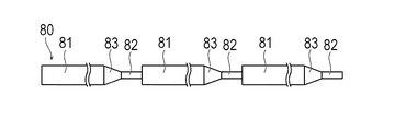
なお、本発明は、上述した実施形態のみに限定されるものではなく、本発明の技術的思想内において当業者により種々変更が可能である。例えば、図6に示す変形例としての芯線80のように、太径部81と細径部82の間の移行部83が、太径部81の一端側にのみ設けられてもよい。これにより、切断後に取り除かれる余剰チューブ(図3(F)の余剰チューブ62を参照)の長さが短くなり、コストの削減、製造エリアの省スペース化を図ることができる。
Note that the present invention is not limited to the above-described embodiments, and various modifications can be made by those skilled in the art within the technical idea of the present invention. For example, a
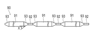
また、図7に示す他の変形例としての芯線90のように、芯線90の軸線に沿う断面における移行部93の外周面の形状の少なくとも一部が曲線で形成されてもよい。これにより、製造されるカテーテル用チューブの剛性が軸線に沿って滑らかかつ傾斜的に変化し、局所的な曲がりが抑制されて、押込み性および耐キンク性に優れたカテーテル用チューブを製造できる。図7では、芯線90の軸線に沿う断面における移行部93の外周面の傾斜角度Xが、細径部92から太径部91へ向かうにしたがって徐々に大きくなり、移行部93の略中央部で最大となり、太径部91へさらに近づくにしたがって徐々に小さくなっている。このような形状とすることで、太径部91と細径部92の間の軸線に沿う剛性をより滑らかかつ傾斜的に変化させることができ、局所的な曲がりが抑制されて、押込み性および耐キンク性に優れたカテーテル用チューブを製造できる。
Moreover, at least a part of the shape of the outer peripheral surface of the
また、内層被覆体51および補強体52の間、または外層被覆体53および補強体52の間、または外層被覆体53の上に、X線不透過性のマーカーを配置してもよい。
Further, a radiopaque marker may be arranged between the inner
また、補強体52は、内層被覆体51および外層被覆体53の間に設けられなくてもよく、例えば外層被覆体53の径方向外側に設けられてもよい。また、補強体52および親水性被覆体54の各々は、設けられなくてもよい。
Further, the reinforcing
また、内層被覆体51および外層被覆体53の少なくとも一方に、電子線またはガンマ線を照射し、材料を架橋させて硬度を高める硬化処理を施してもよい。また、内層被覆体51および外層被覆体53の少なくとも一方に、酸またはアルカリを用いて硬度を低下させる軟化処理を施してもよい。
Further, at least one of the inner layer covering 51 and the outer layer covering 53 may be irradiated with an electron beam or gamma ray to crosslink the material to increase the hardness. Further, at least one of the inner
また、カテーテル用チューブの軸直交断面における断面形状は、円形でなくてもよく、例えば楕円形等であってもよい。また、カテーテル用チューブ内のルーメンは、軸直交断面における断面形状が円形でなくてもよく、例えば、楕円形や半円形等であってもよい。また、カテーテル用チューブは、ルーメンが複数設けられてもよい。 Further, the cross-sectional shape of the catheter tube in the cross section perpendicular to the axis may not be circular, and may be, for example, elliptical. Further, the lumen in the catheter tube may not have a circular cross-sectional shape in the cross section perpendicular to the axis, and may be, for example, an elliptical shape or a semicircular shape. The catheter tube may be provided with a plurality of lumens.
また、芯線は、細径部および太径部が設けられずに、一定外径で形成されてもよい。芯線が一定外径の場合には、切断工程の前に、芯線除去工程を行うことも可能である。 Further, the core wire may be formed with a constant outer diameter without providing the small diameter portion and the large diameter portion. When the core wire has a constant outer diameter, the core wire removal step can be performed before the cutting step.
1 カテーテル、
10 カテーテル用チューブ、
40,80,90 芯線、
41,81,91 太径部、
42,82,92 細径部、
43,83,93 移行部、
51 内層被覆体、
52 補強体、
53 外層被覆体、
54 親水性被覆体、
60 管状連続体、
61 単体チューブ、
63 第1切断部、
64 第2切断部、
A1 太径部の一端側における外層被覆体の厚さ、
A2 太径部の他端側における外層被覆体の厚さ、
A3 細径部の一端側における外層被覆体の厚さ、
A4 細径部の他端側における外層被覆体の厚さ、
D1 太径部の外径、
D2 細径部の外径、
X 傾斜角。
1 catheter,
10 Catheter tube,
40, 80, 90 core wires,
41, 81, 91 Large diameter part,
42, 82, 92 Small diameter part,
43, 83, 93 Transition section,
51 inner layer covering,
52 reinforcements,
53 outer layer covering,
54 hydrophilic covering,
60 tubular continuum,
61 Single tube,
63 1st cutting part,
64 second cutting part,
A1 Thickness of the outer layer covering on one end side of the large diameter portion,
A2 The thickness of the outer layer covering on the other end side of the large-diameter portion,
A3, the thickness of the outer layer covering at one end of the small diameter portion,
A4, the thickness of the outer layer covering on the other end side of the small diameter portion,
D1 Outer diameter of the large diameter part,
D2 Outer diameter of small diameter part,
X Tilt angle.
Claims (7)
前記内層被覆体形成工程よりも後に、熱可塑性樹脂を押出成形により前記芯線の軸線方向へ厚さを変化させつつ前記内層被覆体よりも径方向外側に被覆して外層被覆体を形成する外層被覆体形成工程と、
前記外層被覆体形成工程よりも後に前記芯線上に前記内層被覆体および外層被覆体を備えて得られる管状連続体を、所定の位置で切断して複数の単体チューブを切り出す切断工程と、
前記単体チューブから前記芯線を除去する芯線除去工程と、を有するカテーテル用チューブの製造方法。 An inner layer covering forming step of forming an inner layer covering by coating a resin on the core wire;
After the inner layer covering body forming step, an outer layer covering is formed by covering the outer side of the inner layer covering body in the radial direction while changing the thickness in the axial direction of the core wire by extrusion molding the thermoplastic resin. Body formation process,
A cutting step of cutting a plurality of single tubes by cutting a tubular continuous body obtained by providing the inner layer covering and the outer layer covering on the core wire after the outer layer covering forming step;
And a core wire removing step of removing the core wire from the single tube.
芯線除去工程は、前記切断工程よりも後に実施される請求項2に記載のカテーテル用チューブの製造方法。 In the cutting step, the tubular continuous body is cut at a predetermined position of the large diameter portion and the small diameter portion to cut out a plurality of single tubes,
The method for manufacturing a catheter tube according to claim 2, wherein the core wire removing step is performed after the cutting step.
Priority Applications (1)
| Application Number | Priority Date | Filing Date | Title |
|---|---|---|---|
| JP2012254616A JP2014100323A (en) | 2012-11-20 | 2012-11-20 | Catheter tube manufacturing method |
Applications Claiming Priority (1)
| Application Number | Priority Date | Filing Date | Title |
|---|---|---|---|
| JP2012254616A JP2014100323A (en) | 2012-11-20 | 2012-11-20 | Catheter tube manufacturing method |
Publications (1)
| Publication Number | Publication Date |
|---|---|
| JP2014100323A true JP2014100323A (en) | 2014-06-05 |
Family
ID=51023448
Family Applications (1)
| Application Number | Title | Priority Date | Filing Date |
|---|---|---|---|
| JP2012254616A Pending JP2014100323A (en) | 2012-11-20 | 2012-11-20 | Catheter tube manufacturing method |
Country Status (1)
| Country | Link |
|---|---|
| JP (1) | JP2014100323A (en) |
Cited By (2)
| Publication number | Priority date | Publication date | Assignee | Title |
|---|---|---|---|---|
| CN108327213A (en) * | 2018-02-06 | 2018-07-27 | 苏州海维尔医疗器械有限公司 | Superslide seal wire external coating is dissolved former and its method for coating |
| EP3885859A1 (en) * | 2020-03-27 | 2021-09-29 | Heraeus Deutschland GmbH & Co KG | Increasing production yield of coated wire elements |
-
2012
- 2012-11-20 JP JP2012254616A patent/JP2014100323A/en active Pending
Cited By (4)
| Publication number | Priority date | Publication date | Assignee | Title |
|---|---|---|---|---|
| CN108327213A (en) * | 2018-02-06 | 2018-07-27 | 苏州海维尔医疗器械有限公司 | Superslide seal wire external coating is dissolved former and its method for coating |
| EP3885859A1 (en) * | 2020-03-27 | 2021-09-29 | Heraeus Deutschland GmbH & Co KG | Increasing production yield of coated wire elements |
| US20210304923A1 (en) * | 2020-03-27 | 2021-09-30 | Heraeus Deutschland GmbH & Co. KG | Increasing production yield of coated wire elements |
| US11887754B2 (en) | 2020-03-27 | 2024-01-30 | Heraeus Deutschland GmbH & Co. KG | Increasing production yield of coated wire elements |
Similar Documents
| Publication | Publication Date | Title |
|---|---|---|
| JP2014100339A (en) | Catheter tube manufacturing method and continuous body of catheter tubes | |
| JP4924418B2 (en) | Medical catheter tube and manufacturing method thereof | |
| US20200330725A1 (en) | Catheter devices and methods for making them | |
| KR20070043791A (en) | Catheter tube for medical treatment and method of manufacturing the same | |
| US10946171B2 (en) | Catheter devices and methods for making them | |
| WO2017104465A1 (en) | Catheter and method of manufacturing same | |
| JP2006288943A (en) | Medical catheter tube, and its manufacturing method | |
| JP6088809B2 (en) | CATHETER TUBE MANUFACTURING METHOD, CATHETER TUBE CONTINUOUS AND CATHETER TUBE PRODUCING CORE | |
| JP6124563B2 (en) | Catheter tube manufacturing method and catheter tube continuum | |
| JP2014100323A (en) | Catheter tube manufacturing method | |
| JP2014100327A (en) | Catheter tube manufacturing method | |
| JP2014100321A (en) | Method for manufacturing catheter tube | |
| JP2014100336A (en) | Catheter tube manufacturing method and continuous body of catheter tubes | |
| JP2014100333A (en) | Catheter tube manufacturing method, continuous body of catheter tubes, and core wire for manufacturing catheter tubes | |
| JP2014100328A (en) | Catheter tube manufacturing method | |
| JP2014100330A (en) | Catheter tube manufacturing method | |
| JP2014100324A (en) | Catheter tube manufacturing method and continuous body of catheter tubes | |
| JP2014100331A (en) | Catheter tube manufacturing method | |
| JP2014100326A (en) | Catheter tube manufacturing method | |
| JP2014100332A (en) | Catheter tube manufacturing method, continuous body of catheter tubes, and core wire for manufacturing catheter tubes | |
| JP2006051080A (en) | Medical catheter tube and method for manufacturing the same | |
| JP2014100335A (en) | Catheter tube manufacturing method | |
| JP2014100329A (en) | Catheter tube manufacturing method | |
| JP2006034347A (en) | Catheter tube for medical use and manufacturing method therefor | |
| JP2014100337A (en) | Catheter tube manufacturing method |