JP6088809B2 - CATHETER TUBE MANUFACTURING METHOD, CATHETER TUBE CONTINUOUS AND CATHETER TUBE PRODUCING CORE - Google Patents
CATHETER TUBE MANUFACTURING METHOD, CATHETER TUBE CONTINUOUS AND CATHETER TUBE PRODUCING CORE Download PDFInfo
- Publication number
- JP6088809B2 JP6088809B2 JP2012254618A JP2012254618A JP6088809B2 JP 6088809 B2 JP6088809 B2 JP 6088809B2 JP 2012254618 A JP2012254618 A JP 2012254618A JP 2012254618 A JP2012254618 A JP 2012254618A JP 6088809 B2 JP6088809 B2 JP 6088809B2
- Authority
- JP
- Japan
- Prior art keywords
- diameter portion
- core wire
- catheter tube
- diameter
- tube
- Prior art date
- Legal status (The legal status is an assumption and is not a legal conclusion. Google has not performed a legal analysis and makes no representation as to the accuracy of the status listed.)
- Active
Links
- 238000004519 manufacturing process Methods 0.000 title claims description 47
- 230000007704 transition Effects 0.000 claims description 86
- 238000000034 method Methods 0.000 claims description 34
- 238000005520 cutting process Methods 0.000 claims description 27
- 229920005989 resin Polymers 0.000 claims description 22
- 239000011347 resin Substances 0.000 claims description 22
- 230000008569 process Effects 0.000 claims description 19
- 239000011248 coating agent Substances 0.000 claims description 18
- 238000000576 coating method Methods 0.000 claims description 18
- 230000015572 biosynthetic process Effects 0.000 claims description 9
- 230000002787 reinforcement Effects 0.000 claims description 9
- 238000009751 slip forming Methods 0.000 claims description 9
- 239000011162 core material Substances 0.000 description 144
- 239000000463 material Substances 0.000 description 36
- 239000006185 dispersion Substances 0.000 description 32
- 239000000243 solution Substances 0.000 description 31
- 230000003014 reinforcing effect Effects 0.000 description 29
- 238000000465 moulding Methods 0.000 description 28
- 239000003550 marker Substances 0.000 description 22
- 238000001125 extrusion Methods 0.000 description 15
- 239000000126 substance Substances 0.000 description 11
- 230000002093 peripheral effect Effects 0.000 description 8
- 229920005992 thermoplastic resin Polymers 0.000 description 8
- 238000004804 winding Methods 0.000 description 8
- 239000002585 base Substances 0.000 description 6
- 210000004204 blood vessel Anatomy 0.000 description 6
- 229920001477 hydrophilic polymer Polymers 0.000 description 6
- 238000011084 recovery Methods 0.000 description 6
- 238000005245 sintering Methods 0.000 description 6
- 239000004952 Polyamide Substances 0.000 description 5
- 238000001035 drying Methods 0.000 description 5
- 230000004048 modification Effects 0.000 description 5
- 238000012986 modification Methods 0.000 description 5
- BASFCYQUMIYNBI-UHFFFAOYSA-N platinum Chemical compound [Pt] BASFCYQUMIYNBI-UHFFFAOYSA-N 0.000 description 5
- 229920002647 polyamide Polymers 0.000 description 5
- 238000002360 preparation method Methods 0.000 description 5
- 239000002872 contrast media Substances 0.000 description 4
- 229920001577 copolymer Polymers 0.000 description 4
- 239000003085 diluting agent Substances 0.000 description 4
- 239000000203 mixture Substances 0.000 description 4
- 239000002861 polymer material Substances 0.000 description 4
- 230000001012 protector Effects 0.000 description 4
- 239000002904 solvent Substances 0.000 description 4
- 238000005452 bending Methods 0.000 description 3
- 125000000524 functional group Chemical group 0.000 description 3
- 239000007788 liquid Substances 0.000 description 3
- FPYJFEHAWHCUMM-UHFFFAOYSA-N maleic anhydride Chemical compound O=C1OC(=O)C=C1 FPYJFEHAWHCUMM-UHFFFAOYSA-N 0.000 description 3
- 229910052751 metal Inorganic materials 0.000 description 3
- 239000002184 metal Substances 0.000 description 3
- 238000012545 processing Methods 0.000 description 3
- RTZKZFJDLAIYFH-UHFFFAOYSA-N Diethyl ether Chemical compound CCOCC RTZKZFJDLAIYFH-UHFFFAOYSA-N 0.000 description 2
- YCKRFDGAMUMZLT-UHFFFAOYSA-N Fluorine atom Chemical compound [F] YCKRFDGAMUMZLT-UHFFFAOYSA-N 0.000 description 2
- 239000004677 Nylon Substances 0.000 description 2
- 125000003172 aldehyde group Chemical group 0.000 description 2
- 125000003277 amino group Chemical group 0.000 description 2
- TZCXTZWJZNENPQ-UHFFFAOYSA-L barium sulfate Chemical compound [Ba+2].[O-]S([O-])(=O)=O TZCXTZWJZNENPQ-UHFFFAOYSA-L 0.000 description 2
- 230000008859 change Effects 0.000 description 2
- 230000008602 contraction Effects 0.000 description 2
- 230000007423 decrease Effects 0.000 description 2
- 230000003247 decreasing effect Effects 0.000 description 2
- 229920001971 elastomer Polymers 0.000 description 2
- 239000000806 elastomer Substances 0.000 description 2
- 230000003073 embolic effect Effects 0.000 description 2
- 125000003700 epoxy group Chemical group 0.000 description 2
- 239000000835 fiber Substances 0.000 description 2
- 229910052731 fluorine Inorganic materials 0.000 description 2
- 239000011737 fluorine Substances 0.000 description 2
- 239000002783 friction material Substances 0.000 description 2
- 238000010438 heat treatment Methods 0.000 description 2
- 229920001903 high density polyethylene Polymers 0.000 description 2
- 239000004700 high-density polyethylene Substances 0.000 description 2
- 238000003780 insertion Methods 0.000 description 2
- 230000037431 insertion Effects 0.000 description 2
- IQPQWNKOIGAROB-UHFFFAOYSA-N isocyanate group Chemical group [N-]=C=O IQPQWNKOIGAROB-UHFFFAOYSA-N 0.000 description 2
- 229920001778 nylon Polymers 0.000 description 2
- 229910052697 platinum Inorganic materials 0.000 description 2
- 229920002401 polyacrylamide Polymers 0.000 description 2
- -1 polyethylene Polymers 0.000 description 2
- 229920000642 polymer Polymers 0.000 description 2
- 238000007639 printing Methods 0.000 description 2
- 239000007921 spray Substances 0.000 description 2
- 229920001187 thermosetting polymer Polymers 0.000 description 2
- WFKWXMTUELFFGS-UHFFFAOYSA-N tungsten Chemical compound [W] WFKWXMTUELFFGS-UHFFFAOYSA-N 0.000 description 2
- 229910052721 tungsten Inorganic materials 0.000 description 2
- 239000010937 tungsten Substances 0.000 description 2
- XLYOFNOQVPJJNP-UHFFFAOYSA-N water Substances O XLYOFNOQVPJJNP-UHFFFAOYSA-N 0.000 description 2
- ICGQLNMKJVHCIR-UHFFFAOYSA-N 1,3,2-dioxazetidin-4-one Chemical group O=C1ONO1 ICGQLNMKJVHCIR-UHFFFAOYSA-N 0.000 description 1
- NGNBDVOYPDDBFK-UHFFFAOYSA-N 2-[2,4-di(pentan-2-yl)phenoxy]acetyl chloride Chemical group CCCC(C)C1=CC=C(OCC(Cl)=O)C(C(C)CCC)=C1 NGNBDVOYPDDBFK-UHFFFAOYSA-N 0.000 description 1
- 235000001270 Allium sibiricum Nutrition 0.000 description 1
- 229920000049 Carbon (fiber) Polymers 0.000 description 1
- RYGMFSIKBFXOCR-UHFFFAOYSA-N Copper Chemical compound [Cu] RYGMFSIKBFXOCR-UHFFFAOYSA-N 0.000 description 1
- 229920012753 Ethylene Ionomers Polymers 0.000 description 1
- 244000043261 Hevea brasiliensis Species 0.000 description 1
- 229920002153 Hydroxypropyl cellulose Polymers 0.000 description 1
- 229920003171 Poly (ethylene oxide) Polymers 0.000 description 1
- 239000004698 Polyethylene Substances 0.000 description 1
- 239000002202 Polyethylene glycol Substances 0.000 description 1
- 239000004642 Polyimide Substances 0.000 description 1
- 239000004743 Polypropylene Substances 0.000 description 1
- BQCADISMDOOEFD-UHFFFAOYSA-N Silver Chemical compound [Ag] BQCADISMDOOEFD-UHFFFAOYSA-N 0.000 description 1
- 239000002253 acid Substances 0.000 description 1
- 125000004018 acid anhydride group Chemical group 0.000 description 1
- 239000000853 adhesive Substances 0.000 description 1
- 230000001070 adhesive effect Effects 0.000 description 1
- 239000003513 alkali Substances 0.000 description 1
- 239000000956 alloy Substances 0.000 description 1
- 229910045601 alloy Inorganic materials 0.000 description 1
- IVRMZWNICZWHMI-UHFFFAOYSA-N azide group Chemical group [N-]=[N+]=[N-] IVRMZWNICZWHMI-UHFFFAOYSA-N 0.000 description 1
- 210000000013 bile duct Anatomy 0.000 description 1
- 229910000416 bismuth oxide Inorganic materials 0.000 description 1
- 210000004369 blood Anatomy 0.000 description 1
- 239000008280 blood Substances 0.000 description 1
- 238000009954 braiding Methods 0.000 description 1
- 239000004917 carbon fiber Substances 0.000 description 1
- 125000003178 carboxy group Chemical group [H]OC(*)=O 0.000 description 1
- 238000003486 chemical etching Methods 0.000 description 1
- 238000012993 chemical processing Methods 0.000 description 1
- 150000001875 compounds Chemical class 0.000 description 1
- 230000008878 coupling Effects 0.000 description 1
- 238000010168 coupling process Methods 0.000 description 1
- 238000005859 coupling reaction Methods 0.000 description 1
- 230000007547 defect Effects 0.000 description 1
- 238000003745 diagnosis Methods 0.000 description 1
- IJGRMHOSHXDMSA-UHFFFAOYSA-O diazynium Chemical group [NH+]#N IJGRMHOSHXDMSA-UHFFFAOYSA-O 0.000 description 1
- TYIXMATWDRGMPF-UHFFFAOYSA-N dibismuth;oxygen(2-) Chemical compound [O-2].[O-2].[O-2].[Bi+3].[Bi+3] TYIXMATWDRGMPF-UHFFFAOYSA-N 0.000 description 1
- 238000007598 dipping method Methods 0.000 description 1
- 239000003814 drug Substances 0.000 description 1
- 229940079593 drug Drugs 0.000 description 1
- 230000000694 effects Effects 0.000 description 1
- 239000013013 elastic material Substances 0.000 description 1
- 238000010894 electron beam technology Methods 0.000 description 1
- 239000003822 epoxy resin Substances 0.000 description 1
- 210000003238 esophagus Anatomy 0.000 description 1
- 238000005530 etching Methods 0.000 description 1
- 239000005038 ethylene vinyl acetate Substances 0.000 description 1
- 235000012438 extruded product Nutrition 0.000 description 1
- 238000005242 forging Methods 0.000 description 1
- 230000004927 fusion Effects 0.000 description 1
- 230000005251 gamma ray Effects 0.000 description 1
- 239000003365 glass fiber Substances 0.000 description 1
- PCHJSUWPFVWCPO-UHFFFAOYSA-N gold Chemical compound [Au] PCHJSUWPFVWCPO-UHFFFAOYSA-N 0.000 description 1
- 229910052737 gold Inorganic materials 0.000 description 1
- 239000010931 gold Substances 0.000 description 1
- 230000005484 gravity Effects 0.000 description 1
- 238000000227 grinding Methods 0.000 description 1
- 239000012943 hotmelt Substances 0.000 description 1
- 125000002887 hydroxy group Chemical group [H]O* 0.000 description 1
- 239000001863 hydroxypropyl cellulose Substances 0.000 description 1
- 235000010977 hydroxypropyl cellulose Nutrition 0.000 description 1
- 238000007373 indentation Methods 0.000 description 1
- 239000007924 injection Substances 0.000 description 1
- 238000002347 injection Methods 0.000 description 1
- 230000003993 interaction Effects 0.000 description 1
- 230000009545 invasion Effects 0.000 description 1
- 230000001050 lubricating effect Effects 0.000 description 1
- 238000010128 melt processing Methods 0.000 description 1
- 229920003052 natural elastomer Polymers 0.000 description 1
- 229920005615 natural polymer Polymers 0.000 description 1
- 229920001194 natural rubber Polymers 0.000 description 1
- 239000002245 particle Substances 0.000 description 1
- 210000005259 peripheral blood Anatomy 0.000 description 1
- 239000011886 peripheral blood Substances 0.000 description 1
- 239000002504 physiological saline solution Substances 0.000 description 1
- 238000005498 polishing Methods 0.000 description 1
- 229920001200 poly(ethylene-vinyl acetate) Polymers 0.000 description 1
- 229920002492 poly(sulfone) Polymers 0.000 description 1
- 229920001230 polyarylate Polymers 0.000 description 1
- 229920001083 polybutene Polymers 0.000 description 1
- 239000004417 polycarbonate Substances 0.000 description 1
- 229920000515 polycarbonate Polymers 0.000 description 1
- 229920000647 polyepoxide Polymers 0.000 description 1
- 229920000728 polyester Polymers 0.000 description 1
- 229920000573 polyethylene Polymers 0.000 description 1
- 229920001223 polyethylene glycol Polymers 0.000 description 1
- 229920001721 polyimide Polymers 0.000 description 1
- 229920000098 polyolefin Polymers 0.000 description 1
- 229920001155 polypropylene Polymers 0.000 description 1
- 229920002635 polyurethane Polymers 0.000 description 1
- 239000004814 polyurethane Substances 0.000 description 1
- 229920003225 polyurethane elastomer Polymers 0.000 description 1
- 239000004800 polyvinyl chloride Substances 0.000 description 1
- 229920000915 polyvinyl chloride Polymers 0.000 description 1
- 239000000843 powder Substances 0.000 description 1
- 238000003825 pressing Methods 0.000 description 1
- 230000009467 reduction Effects 0.000 description 1
- 230000001105 regulatory effect Effects 0.000 description 1
- 238000010008 shearing Methods 0.000 description 1
- 229920002050 silicone resin Polymers 0.000 description 1
- 229910052709 silver Inorganic materials 0.000 description 1
- 239000004332 silver Substances 0.000 description 1
- 239000010935 stainless steel Substances 0.000 description 1
- 229910001220 stainless steel Inorganic materials 0.000 description 1
- 229920001059 synthetic polymer Polymers 0.000 description 1
- 229940126585 therapeutic drug Drugs 0.000 description 1
- 210000003437 trachea Anatomy 0.000 description 1
- 210000003708 urethra Anatomy 0.000 description 1
- 238000003466 welding Methods 0.000 description 1
- 238000005491 wire drawing Methods 0.000 description 1
Images


Description
本発明は、血管等の管腔内や体腔内で使用されるカテーテルに用いられるカテーテル用チューブの製造方法、カテーテル用チューブの連続体およびカテーテル用チューブ製造用の芯線に関する。 The present invention relates to a method for producing a catheter tube used in a catheter used in a lumen such as a blood vessel or a body cavity, a continuous catheter tube, and a core wire for producing a catheter tube.
近年、外科的侵襲が非常に低いという理由から、カテーテルを用いた血管等の管腔内や体腔内の治療が盛んに行われている。例えば、体内の複雑に分岐した血管へ選択的に導入して使用されるカテーテルは、一般的に、血管へあらかじめ導入されるガイドワイヤーに沿って選択的に押し込まれて、治療用の薬剤や診断用の造影剤等を手元側(基端側)から先端側へ流通させる。このため、カテーテルを構成する長尺なカテーテル用チューブは、基端側の内外径を大きくすることで、剛性を高めて押込み性(プッシャビリティー)を充分に持たせつつ薬剤や造影剤の注入特性を確保し、先端側の内外径を手元側よりも細くし、柔軟にすることで末梢血管への到達性やガイドワイヤーへの追従性を高めている。 In recent years, treatment in a lumen such as a blood vessel or a body cavity using a catheter has been actively performed for the reason that surgical invasion is very low. For example, catheters that are selectively introduced into complex branched blood vessels in the body are typically selectively pushed along a guide wire that is pre-introduced into the blood vessel to provide therapeutic drugs and diagnostics. The contrast agent for use is distributed from the proximal side (base end side) to the distal end side. For this reason, the long catheter tube that constitutes the catheter increases the inner and outer diameters on the proximal end side, thereby increasing the rigidity and providing sufficient pushability. By securing the characteristics and making the inner and outer diameters on the tip side thinner than the proximal side and making it flexible, the reachability to the peripheral blood vessels and the followability to the guide wire are enhanced.
このようなカテーテル用チューブの製造方法として、例えば特許文献1には、外径の異なる太径部および細径部が所定の間隔で連続してなる芯線上に熱可塑性樹脂を被覆成形して被覆体を形成し、複数のカテーテル用チューブを同一の芯線上に連続体として形成した後、連続体を各々のカテーテル用チューブ毎に芯線とともに切断し、芯線を引き抜いて除去してカテーテル用チューブを得る方法が記載されている。
As a method for manufacturing such a catheter tube, for example, in
上述した特許文献1に記載の方法で用いられる芯線は、太径部の両端側に、太径部から細径部へ向かって縮径される部位が対称的に形成されており、一方の縮径されている部位上に被覆される部分は、不用な部位として取り除かれている。このため、製造コストが高くなり、広い製造エリアが必要となる。
The core wire used in the method described in
本発明は、上述した課題を解決するためになされたものであり、複数のカテーテル用チューブを同一の芯線を用いて連続的に製造しつつ、不用な部位を極力減少させて、製造コストの低減および製造エリアの省スペース化を図ることが可能なカテーテル用チューブの製造方法、カテーテル用チューブの連続体、およびカテーテル用チューブ製造用の芯線を提供することを目的とする。 The present invention has been made to solve the above-described problems, and while continuously manufacturing a plurality of catheter tubes using the same core wire, unnecessary portions are reduced as much as possible to reduce manufacturing costs. Another object of the present invention is to provide a catheter tube manufacturing method, a catheter tube continuum, and a catheter tube manufacturing core wire capable of saving space in the manufacturing area.
上記目的を達成するカテーテル用チューブの製造方法は、外径の異なる太径部および細径部、前記太径部の一端側に設けられて前記太径部から前記細径部まで縮径して形成される第1移行部、並びに前記太径部の他端側に設けられて前記太径部から他の細径部まで縮径して形成されるとともに軸線に対する傾斜角が前記第1移行部よりも大きく90度である第2移行部を備える単位構造が予め所定の間隔で連続的に形成された芯線上に、樹脂を被覆して被覆体を形成する被覆体形成工程と、前記被覆体形成工程よりも後に、前記芯線上に得られる管状連続体を前記太径部および細径部の所定の位置で前記芯線とともに切断して複数の単体チューブを切り出す切断工程と、前記単体チューブから前記芯線を除去する芯線除去工程と、を有するカテーテル用チューブの製造方法である。 A method of manufacturing a catheter tube that achieves the above-described object includes a large-diameter portion and a small-diameter portion having different outer diameters, provided on one end side of the large-diameter portion, and reduced in diameter from the large-diameter portion to the small-diameter portion. The first transition portion to be formed, and the first transition portion provided on the other end side of the large-diameter portion and formed by reducing the diameter from the large-diameter portion to another small-diameter portion and having an inclination angle with respect to the axis line continuously formed on the core wire in advance a predetermined interval unit structure is provided with a second transition portion is sized rather 90 degrees than the covering body forming step of forming a coating member covering the resin, the coating A cutting step of cutting a plurality of single tubes by cutting a tubular continuous body obtained on the core wire together with the core wires at predetermined positions of the large diameter portion and the small diameter portion after the body forming step; A core wire removing step for removing the core wire. It is a manufacturing method of the ether tube.
上記のように構成したカテーテル用チューブの製造方法は、芯線の第2移行部の傾斜角が、第1移行部よりも大きいため、第2移行部の軸線方向の長さが短くなり、第2移行部上に形成される不用な部位を極力減少させて、製造コストの低減および製造エリアの省スペース化を図ることができる。 In the manufacturing method of the catheter tube configured as described above, since the inclination angle of the second transition portion of the core wire is larger than that of the first transition portion, the length of the second transition portion in the axial direction is shortened. Unnecessary parts formed on the transition portion can be reduced as much as possible, thereby reducing the manufacturing cost and saving the manufacturing area.
前記第2移行部の傾斜角が90度であるようにすれば、第2移行部の軸線方向の長さを最小化でき、第2移行部上に形成される不用な部位をより減少させて、製造コストの低減および製造エリアの省スペース化を図ることができる。 If the inclination angle of the second transition portion is 90 degrees, the length of the second transition portion in the axial direction can be minimized, and unnecessary portions formed on the second transition portion can be further reduced. Thus, the manufacturing cost can be reduced and the manufacturing area can be saved.
前記被覆体形成工程よりも後に、前記被覆体よりも径方向外側に樹脂を被覆して外層被覆体を形成する外層被覆体形成工程をさらに有するようにすれば、複数の層からなる多層構造のカテーテル用チューブを、一体的に連なる管状連続体を用いて効率的に製造できる。 After the covering body forming step, if it further comprises an outer layer covering body forming step for forming an outer layer covering body by coating a resin radially outward from the covering body, a multilayer structure composed of a plurality of layers is formed. A catheter tube can be efficiently manufactured using a continuous tubular body.
前記被覆体形成工程よりも後に、前記被覆体上よりも径方向外側に線材からなる補強体を形成する補強体形成工程をさらに有するようにすれば、製造されるカテーテル用チューブを部位に応じて補強でき、押込み性および耐キンク性を向上させることができる。 After the covering body forming step, if it further includes a reinforcing body forming step for forming a reinforcing body made of a wire material on the radially outer side than on the covering body, the manufactured catheter tube according to the site. It can reinforce and can improve indentation property and kink resistance.
前記芯線の軸線に沿う断面における前記第1移行部の外周面の形状が曲線を有するようにすれば、製造されるカテーテル用チューブの剛性が軸線に沿って滑らかかつ傾斜的に変化し、局所的な曲がりが抑制されて、押込み性および耐キンク性に優れたカテーテル用チューブを製造できる。 If the shape of the outer peripheral surface of the first transition portion in the cross section along the axis of the core wire has a curve, the rigidity of the manufactured catheter tube changes smoothly and in an inclined manner along the axis. Therefore, it is possible to manufacture a catheter tube excellent in indentability and kink resistance.
カテーテル用チューブの中間体である単体チューブが同一の芯線上に連続的に複数形成されるカテーテル用チューブの連続体であって、外径の異なる太径部および細径部、前記太径部の一端側に設けられて前記太径部から前記細径部まで縮径して形成される第1移行部、並びに前記太径部の他端側に設けられて前記太径部から他の細径部まで縮径して形成されるとともに軸線に対する傾斜角が前記第1移行部よりも大きく90度である第2移行部を備える単位構造が所定の間隔で連続的に形成された芯線と、前記芯線上に樹脂を被覆して形成された被覆体と、を有するカテーテル用チューブの連続体であれば、芯線の第2移行部の傾斜角が第1移行部よりも大きいため、第2移行部の軸線方向の長さが短くなり、第2移行部上に形成される不用な部位を極力減少させて、製造コストの低減および製造エリアの省スペース化を図ることができる。 A single tube, which is an intermediate body of a catheter tube, is a continuous body of catheter tubes in which a plurality of continuous tubes are formed on the same core wire, and a large-diameter portion and a small-diameter portion having different outer diameters, A first transition portion provided on one end side and formed by reducing the diameter from the large diameter portion to the small diameter portion, and another diameter on the other end side of the large diameter portion provided from the large diameter portion. a core wire unit structure comprising a second transition portion inclination angle relative to the axis is large rather 90 degrees than the first transition portion is continuously formed at predetermined intervals while being formed reduced in diameter to parts, Since the inclination angle of the second transition part of the core wire is larger than that of the first transition part, the second transition is performed in a continuous body of a catheter tube having a covering formed by coating a resin on the core wire. The length of the axial direction of the part is shortened, and a defect formed on the second transition part Such by site as much as possible to reduce the, it is possible to save the space of the reduced and manufacturing area of manufacturing cost.
前記連続体に設けられる前記第2移行部の傾斜角が90度であるようにすれば、第2移行部の軸線方向の長さを最小化でき、第2移行部上に形成される不用な部位をより減少させて、製造コストの低減および製造エリアの省スペース化を図ることができる。 If the inclination angle of the second transition portion provided in the continuum is 90 degrees, the length of the second transition portion in the axial direction can be minimized, and it is unnecessary to be formed on the second transition portion. By reducing the number of parts, it is possible to reduce manufacturing costs and save space in the manufacturing area.
前記連続体は、前記被覆体よりも径方向外側に、樹脂により形成される外層被覆体をさらに有するようにすれば、複数の層からなる多層構造のカテーテル用チューブを、一体的に連なる管状連続体を用いて効率的に製造できる。 If the continuous body further includes an outer layer covering body formed of a resin on the outer side in the radial direction than the covering body, a multi-layered catheter tube composed of a plurality of layers is integrated into a continuous tubular structure. It can be manufactured efficiently using the body.
前記連続体は、前記被覆体および前記外層被覆体の間に、線材からなる補強体をさらに有するようにすれば、製造されるカテーテル用チューブを部位に応じて補強でき、押込み性および耐キンク性を向上させることができる。 If the continuous body further includes a reinforcing body made of a wire between the covering body and the outer layer covering body, the catheter tube to be manufactured can be reinforced according to the part, and the pushability and kink resistance can be improved. Can be improved.
前記連続体は、前記芯線の軸線に沿う断面における前記第1移行部の外周面の形状が曲線を有して形成されるようにすれば、芯線から引き抜かれて製造されるカテーテル用チューブの剛性が軸線に沿って滑らかかつ傾斜的に変化し、局所的な曲がりが抑制されて、押込み性および耐キンク性に優れたカテーテル用チューブを製造できる。 If the shape of the outer peripheral surface of the first transition portion in the cross section along the axis of the core wire is formed with a curve, the continuous body has rigidity of the catheter tube manufactured by being drawn out from the core wire. Changes smoothly and inclined along the axis, local bending is suppressed, and a catheter tube excellent in pushability and kink resistance can be manufactured.
以下、図面を参照して、本発明の実施の形態を説明する。なお、図面の寸法比率は、説明の都合上、誇張されて実際の比率とは異なる場合がある。 Embodiments of the present invention will be described below with reference to the drawings. In addition, the dimension ratio of drawing is exaggerated on account of description, and may differ from an actual ratio.
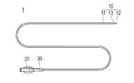
本実施形態に係るカテーテル用チューブの製造方法により製造されたカテーテル用チューブ10は、図1に示すように、血管、胆管、気管、食道、尿道、またはその他の生体管腔内や体腔内に挿入されて治療や診断等を行うためのカテーテル1に用いられる。カテーテル1は、長尺なカテーテル用チューブ10と、カテーテル用チューブ10の基端に連結されるハブ20と、カテーテル用チューブ10およびハブ20の連結部位に設けられる耐キンクプロテクタ30と、を有している。なお、本明細書では、管腔に挿入する側を「先端」若しくは「先端側」、操作する手元側を「基端」若しくは「基端側」と称することとする。
A
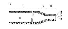
カテーテル用チューブ10は、図1,2に示すように、可撓性を有する管状の部材であり、所定の外径および内径を有するチューブ基端部11と、チューブ基端部11より小さい外径および内径を有するチューブ先端部12と、チューブ基端部11およびチューブ先端部12の間で外径および内径が軸線方向に向かって徐々に変化するチューブ移行部13と、を有している。カテーテル用チューブ10は、基端から先端にかけて内部にルーメン14が形成されている。ルーメン14は、例えばガイドワイヤー用ルーメンとして機能するものであり、カテーテル1の生体管腔内への挿入時には、ガイドワイヤーが挿通される。また、ルーメン14は、薬液や塞栓物質、造影剤等の通路として用いることもできる。
As shown in FIGS. 1 and 2, the
カテーテル用チューブ10は、複数の層で構成されており、最内層を構成する内層15と、内層15の外側に形成される補強層16と、内層15および補強層16の外側に形成される外層17と、外層17の外側に被覆される親水層18と、マーカー19とを備えている。なお、内層15、補強層16、外層17および親水層18の構成および材料は、後述する製造方法にて詳細に説明する。
The
ハブ20は、カテーテル用チューブ10の基端部が接着剤、熱融着または止具(図示せず)等により液密に固着されている。ハブ20は、ルーメン14内へのガイドワイヤーの挿入口、ルーメン14内への薬液や塞栓物質、造影剤等の注入口等として機能し、また、カテーテル1を操作する際の把持部としても機能する。ハブ20の材料は、特に限定されないが、例えば、ポリカーボネート、ポリアミド、ポリサルホン、ポリアリレート、メタクリレート−ブチレン−スチレン共重合体等の熱可塑性樹脂が好適に使用できる。
In the
耐キンクプロテクタ30は、カテーテル用チューブ10の周囲を囲むように設けられる弾性材料からなり、カテーテル用チューブ10とハブ20の連結部位におけるカテーテル用チューブ10のキンクを抑制する。耐キンクプロテクタ30の材料は、例えば、天然ゴム、シリコーン樹脂等が好適に使用できる。
The
次に、本実施形態に係るカテーテル用チューブ10の製造方法について説明する。カテーテル用チューブ10は、長尺な芯線40を準備する芯線準備工程(図3(A))と、芯線40上に内層被覆体51(被覆体)を形成する内層被覆体形成工程(被覆体形成工程)(図3(B))と、内層被覆体51上の少なくとも一部に補強体52を形成する補強体形成工程(図3(C))と、マーカー19を補強体52の上に配置するマーカー配置工程(図3(D))と、マーカー配置工程後に得られるカテーテル用チューブの連続体65を切断して単体チューブ61を切り出す切断工程(図3(E))と、外層被覆体53を形成する外層被覆体形成工程(図3(F))と、芯線40を延伸させる芯線延伸工程(図3(G))と、各単体チューブ61から芯線40を除去する芯線除去工程(図3(H))と、親水性被覆体54を被覆する親水性被覆体形成工程(図3(I))と、を有している。芯線40上に形成される内層被覆体51、補強体52、外層被覆体53および親水性被覆体54は、最終的に、カテーテル用チューブ10の内層15、補強層16、外層17および親水層18となる。
Next, a method for manufacturing the
芯線準備工程は、図3(A)に示すように、芯線40を切削、研磨、研削、鍛造、溶接、割りダイスを用いた引抜き延伸等の機械的加工、または、エッチング等の化学的加工により、太径部41、細径部42および移行部43を有するように加工する工程、または、上記のような加工が施された芯線40を購入等により準備する工程である。
As shown in FIG. 3 (A), the core wire preparation step is performed by mechanical processing such as drawing, drawing, or the like using a cutting die, cutting, polishing, grinding, forging, welding, split die, or chemical processing such as etching. , A step of processing to have the large-
芯線準備工程において準備される芯線40は、所定の外径を有する太径部41と、太径部41より小さい外径を有する細径部42と、太径部41および細径部42の間で外径が芯線40の軸線方向に向かって徐々に変化する第1移行部43および第2移行部44と、を有する単位構造45が、所定の間隔で連続的に複数並んで構成されている。細径部42の外径D2に対する太径部41の外径D1の比率(D1/D2)は、1.00を超えて1.31以下であることが好ましく、より好ましくは1.30以下であり、さらに好ましくは1.22以下である。比率(D1/D2)は1より大きい。比率(D1/D2)が1.31以下であることで、芯線延伸工程において細径部42のみならず太径部41も良好に延伸させ、細径部42のみの細りを抑制して、芯線除去工程において芯線40を良好に除去することが可能となり、実使用に耐え得るカテーテル用チューブ10を製造可能となる。比率(D1/D2)が1.22以下であれば、細径部42のみの細りがより確実に抑制されて、芯線除去工程において芯線40をより確実に除去することが可能となり、より良好なカテーテル用チューブ10を製造可能となる。太径部41の一端側に形成される第1移行部43の軸線に対する傾斜角X1は、太径部41の他端側に形成される第2移行部44の軸線に対する傾斜角X2よりも小さい。一例として、太径部41の長さL1は1800mm、細径部42の長さL2は150mm、第1移行部43の長さL3は50mm、太径部41の外径D1は0.55〜0.6mm、細径部42の外径D2は0.45〜0.50mmとすることができるが、寸法はこれに限定されない。また、一例として、第1移行部43の傾斜角X1は0.01〜10度、第2移行部44の軸線に対する傾斜角X2は70〜90度とすることができ、具体的には、傾斜角X1は3度、第2移行部44の軸線に対する傾斜角X2は90度とすることができるが、寸法はこれに限定されない。
The
芯線40の材料は、銅線、ステンレス軟線等延伸できる金属、または、ポリアミド(PA)等の樹脂ストランド等を適用でき、その断面は円形に限定されず、楕円、半円、多角形等の任意の形状とすることができる。なお、上記のような芯線40は、購入等により容易に準備することができる。
The material of the
芯線準備工程の後には、図3(B)に示すように、芯線40上に内層被覆体51を形成する(内層被覆体形成工程(被覆体形成工程))。内層被覆体51の材料は、熱可塑性樹脂や熱硬化性樹脂等を適用でき、フッ素系樹脂、高密度ポリエチレン(HDPE)等の低摩擦材料等が好ましい。 After the core wire preparation step, as shown in FIG. 3B, an inner layer covering 51 is formed on the core wire 40 (an inner layer covering step (covering step)). As the material of the inner layer covering 51, a thermoplastic resin, a thermosetting resin, or the like can be applied, and a low friction material such as a fluorine-based resin or high-density polyethylene (HDPE) is preferable.
内層被覆体51には、X線不透過物質を混合してもよい。なお、内層被覆体51をフッ素系樹脂等の低摩摩擦材料で形成する場合には、外側に他の材料を被覆できるように、内層被覆体51の外側表面に、ケミカルエッチング等により粗面化処理を施すことが好ましい。 The inner layer covering 51 may be mixed with a radiopaque material. When the inner layer covering 51 is formed of a low friction material such as a fluororesin, the outer surface of the inner layer covering 51 is roughened by chemical etching or the like so that other materials can be covered on the outer side. It is preferable to perform the treatment.
内層被覆体51の材料に熱可塑性樹脂を用いる場合には、押出成形機にて所定の成形温度(ダイス温度)で所定の引き取り速度で押出成形することができる。これにより、略同一肉厚の押出成形体(内層被覆体51)を得ることができる。一例として、太径部41に対応する部位の内層被覆体51の外径を0.57〜0.76mm、細径部42に対応する部位の内層被覆体51の外径を0.47〜0.53mmとすることができるが、寸法はこれに限定されない。なお、引き取り速度を調整することで、部位に応じて肉厚を変化させることもできる。
When a thermoplastic resin is used as the material of the inner layer covering 51, it can be extruded at a predetermined take-up speed at a predetermined molding temperature (die temperature) with an extruder. Thereby, the extrusion molding (inner layer covering 51) of substantially the same thickness can be obtained. As an example, the outer diameter of the inner layer covering 51 in the portion corresponding to the
押出成形法を概説すれば、図4に示すような一般的な押出成形機100を用いて、芯材W(ここでは、芯線40)上に熱可塑性樹脂の層(ここでは、内層被覆体51)を成形する。押出成形機100は、加熱溶融した材料を押し出す押出機101と、押出機101から押し出された樹脂を押出口102から押し出す金型103と、金型103を貫通して押出口102の中心に位置する芯材Wを引き取る引取機105と、芯材Wが巻回されて保持されるとともに金型103へ芯材Wを供給する供給ロール106と、押出成形が完了した芯材Wを回収する回収ロール107と、を備えている。芯材W上に材料を押出成形する際には、押出機101により加熱溶融した材料を金型103に供給して、供給ロール106から送り出されて押出口102に位置する芯材Wを引取機105により引き取りつつ押出口102から芯材W上に材料を連続的に供給して、芯材W上に材料を被覆させる。材料が被覆された芯材Wは、被覆された材料が固化した後に回収ロール107に巻回されて回収される。引取機105による引き取り速度を変更することで、押し出される成形品の外径を任意に変更することができる。なお、押出成形の前工程から芯材Wを直接受け取り、後工程へ熱可塑性樹脂が被覆された芯材Wを直接引き渡すのであれば、供給ロール106および回収ロール107は、設けられなくてもよい。
An outline of the extrusion molding method is as follows. Using a general
なお、内層被覆体形成工程では、内層被覆体51を押出成形により成形するのではなしに、ディップ成形によって成形してもよい。ディップ成形による方法を概説すれば、まず、図5に示すような容器200内に、材料である樹脂を溶剤に溶解した溶液Rまたは希釈剤中に分散させた分散液Rを収容し、容器200の底に設けられて液密性を維持しつつ芯材W(ここでは、芯線40)を挿通可能である柔軟な弁体201を介して、芯材Wが巻回されて保持される供給ロール202から芯材Wを供給し、芯材Wを下方から容器200内に挿入する。そして、容器200内で溶液Rまたは分散液Rに芯材Wをディッピング(浸漬)させた後に、容器200の上方へ引き抜く。これにより、芯材Wの外周面に溶液Rまたは分散液Rを付着させ、芯材Wに付着させた溶液Rまたは分散液Rを熱風やヒータ等によって加熱して乾燥させ、フッ素系樹脂等の分散液Rを用いる場合にはさらに焼結させて、内層被覆体51を形成する。材料が被覆された芯材Wは、被覆された材料が固化した後に回収ロール203に巻回されて回収される。溶剤や希釈剤には、通常用いられているものを適用することができる。容器200からの引き上げ速度を変更することで、芯材Wに付着される溶液Rまたは分散液Rの膜厚を任意に変更し、内層被覆体51の厚さを任意に変更することができる。膜厚は、溶液Rまたは分散液Rの密度、表面張力、粘度、重力および引き上げ速度が相互に作用して決定され、容器200からの引き上げ速度を遅くすると、芯材Wに付着される溶液Rまたは分散液Rの膜厚を増加させることができ、引き上げ速度を速くすると、芯材Wに付着される溶液Rまたは分散液Rの膜厚を減少させることができる。例えば、太径部41よりも細径部42に対応する部位の膜厚を薄くして、移行部43に対応する部位の膜厚を、漸次的に変化させることもできる。
In the inner layer covering body forming step, the inner
また、溶液Rまたは分散液Rの粘度が高いと、被覆される厚さが不均一となりやすいため、被覆される膜厚が均一となる程度に粘度を低く設定し、ディップ成形を複数回繰り返し行うことで、被覆させる膜厚を徐々に増加させて、被覆厚さを高精度に制御することができる。ディップ成形を繰り返し行う際には、材料が被覆された芯材Wが回収された回収ロール203を、容器200の下方へ移動させて供給ロール202とし、再びディップ成形を行うことができる。ディップ成形を繰り返し行う際には、一回毎に、溶液Rまたは分散液Rを熱風やヒータ等によって加熱して乾燥および焼結させることが好ましい。
Also, if the viscosity of the solution R or dispersion R is high, the coating thickness tends to be non-uniform, so the viscosity is set low enough to make the coating film thickness uniform, and dip molding is repeated multiple times. Thus, the coating thickness can be gradually increased, and the coating thickness can be controlled with high accuracy. When the dip molding is repeatedly performed, the
また、ディップ成形を複数回繰り返し行う際には、芯線40の同じ方向へ引き上げてディップ成形するのではなしに、少なくとも1回は逆方向へ引き上げてディップ成形することが好ましく、より好ましくは、1回ずつ方向を変えながらディップ成形することが好ましい。少なくとも1回は逆方向からディップ成形することで、引き上げ方向に依存する膜厚の偏りを抑制して膜厚を均一化でき、1回ずつ方向を変えながらディップ成形することで、引き上げ方向による膜厚の偏りを最大限に抑制して、膜厚をより均一とすることができる。特に、外径が変化する芯線40においては、外径が変化する部位において、引き上げ方向に依存する膜厚の偏りが生じやすいことから、太径部41および細径部42が形成される芯線40にディップ成形を施す際に、少なくとも1回は逆方向からディップ成形することで、膜厚の均一化において高い効果が発揮される。
Further, when the dip molding is repeated a plurality of times, it is preferable that the dip molding is performed at least once in the opposite direction, rather than the dip molding by pulling up in the same direction of the
なお、一回のディップ成形のステップごとに乾燥・焼結させることもできるが、乾燥・焼結させることなしに連続して複数回ディップ成形した後、乾燥・焼結させることもできる。このように乾燥・焼結させることなしに連続して複数回ディップ成形することにより、所望の部位での厚みを細かく設定することができる。 In addition, although it can dry and sinter for every step of dip forming, it can also be dried and sintered after dip forming continuously several times without drying and sintering. Thus, the thickness in a desired part can be finely set by carrying out the dip molding continuously several times without drying and sintering.
また、ディップ成形を繰り返し行う際に、芯線40の部位に応じて繰り返し回数を変化させることができる。このための方法の一例として、繰り返し回数を多くしたい部位を引き上げ、当該部位に被覆される溶液Rまたは分散液Rを乾燥・焼結させた後、上方向へ移動していた芯線40を下方向へ移動させて、繰り返し回数を多くしたい部位を溶液Rまたは分散液R内に浸漬させる。この後、再び芯線40を上方向へ移動させて、繰り返し回数を多くしたい部位を再び引き上げて、溶液Rまたは分散液Rをさらに被覆させることができる。これを繰り返すことで、部位に応じた所望の繰り返し回数のディップ成形を行うことができる。このように、芯線40の移動方向を切り替えながら、ディップ成形の繰り返し回数を部位に応じて適宜設定することができる。したがって、例えば、ディップ成形の繰り返し回数が、移行部>太径部>細径部となるように、または太径部>移行部>細径部となるように設定することができる。なお、A>Bとは、Aにおける繰り返し回数がBにおける繰り返し回数より多いことを意味する。これらのうち、移行部で繰り返し数が最も多くなるようにディップ成形をすると、移行部での厚みを可変的に変化させることができ、好ましい。この方法においても、一回のディップ成形のステップごとに乾燥・焼結させることができるが、乾燥・焼結させることなしに連続して複数回ディップ成形した後、乾燥・焼結させてもよい。
Further, when the dip molding is repeatedly performed, the number of repetitions can be changed according to the portion of the
また、芯線40を移動させるのではなしに、図5で示される溶液Rまたは分散液Rの液量Hを変化させて深さを変化させることで、引き上げ位置、引き上げ速度および引き上げ方向(上方向または下方向)を調整することもできる。
In addition, the
また、芯材Wを、芯材Wの軸線を中心に回転させつつ容器200から引き上げることで、芯材Wに被覆される溶液Rまたは分散液Rに遠心力を作用させて、被覆される量を任意に変更することもできる。すなわち、芯材Wの回転速度が速いほど作用する遠心力が増加して、芯材Wに被覆される溶液Rまたは分散液Rの膜厚を減少させることができ、芯材Wの回転速度が遅いほど作用する遠心力が減少して、芯材Wに被覆される溶液Rまたは分散液Rの膜厚を増加させることができる。例えば、太径部41を引き上げる際よりも、細径部42を引き上げる際の回転速度を増加させることで、細径部42に被覆される膜厚を、太径部41に被覆される膜厚よりも薄くすることができる。そして、移行部43を引き上げる際に、芯線40の回転速度を徐々に変化させることで、移行部43における膜厚を、太径部41と細径部42の間で滑らかかつ傾斜的に変化させることができる。これにより、製造されるカテーテル用チューブ10の先端側を基端側よりも柔軟にすることができる。また、芯線40の外径が大きいほど、作用する遠心力が大きくなるため、被覆される溶液Rまたは分散液Rの膜厚を一定にするために、外径が変化する部位において回転速度を調整することも可能である。
In addition, the core material W is lifted from the
本実施形態では、芯材Wが供給ロール202から供給され、回収ロール203に回収されるため、供給ロール202および回収ロール203を、容器200内の芯材Wの軸線を中心に回転させることが好ましいが、容器200内の芯材Wを回転させることが可能であれば、装置の構成は限定されない。
In the present embodiment, since the core material W is supplied from the
また、芯材Wを回転させつつ容器200から引き上げる際に、溶液Rまたは分散液Rに粒子や繊維等の混合物が混合されている場合には、混合物に配向を与えることができる。
Further, when the core material W is pulled up from the
ディップ成形を回転させながら複数回繰り返し行う際には、芯線40を毎回同じ方向へ回転させるのではなしに、少なくとも1回は逆回転させつつディップ成形することが好ましく、より好ましくは、1回ずつ回転方向を逆にしながらディップ成形することが好ましい。少なくとも1回は逆回転させつつディップ成形することで、回転方向に依存する膜厚の偏りを抑制して膜厚を均一化でき、1回ずつ回転方向を変えながらディップ成形することで、回転方向に依存する膜厚の偏りを最大限に抑制して、膜厚をより均一とすることができる。
When the dip forming is repeated a plurality of times while rotating, it is preferable to perform the dip forming while rotating the
芯材Wに被覆される溶液Rまたは分散液Rの膜厚を減少させたい場合には、引き上げ速度で制御しようとすると引き上げ速度を遅くする必要があるが、上述のように芯材Wの回転速度で制御すれば、引き上げ速度を遅くすることなしに回転速度を増加させることで調整可能であるため、製造時間を短縮できる。 When it is desired to reduce the film thickness of the solution R or the dispersion R coated on the core material W, it is necessary to slow the pulling speed if it is controlled by the pulling speed. If it is controlled by speed, it can be adjusted by increasing the rotational speed without slowing the pulling speed, so that the manufacturing time can be shortened.
このように、溶液Rまたは分散液Rの粘度、引き上げ速度、引き上げ方向、引き上げ部位、溶液Rまたは分散液Rの液量(容器200中での深さ)、ディップ成形の繰り返し回数、回転速度および回転方向を調整することで、被覆される内層被覆体51の被覆厚さおよび製造時間を、高精度に制御することができる。 Thus, the viscosity of the solution R or the dispersion R, the pulling speed, the pulling direction, the pulling site, the liquid amount of the solution R or the dispersion R (depth in the container 200), the number of repetitions of dip molding, the rotation speed, and By adjusting the rotation direction, the coating thickness and manufacturing time of the inner layer covering 51 to be coated can be controlled with high accuracy.
なお、内層被覆体51をディップ成形できるのであれば、上記のような容器200でなくてもよく、例えば、容器200の底から芯材Wを挿通させるのではなしに、容器の上方から芯材Wを溶液Rまたは分散液Rにディッピング(浸漬)させ、芯材Wを湾曲させつつ、再び上方へ引き上げるようにしてもよい。また、芯材Wの外周面に溶液Rまたは分散液Rを付着させた後、所定の内径を有するダイ(図示せず)を通過させて付着される溶液Rまたは分散液Rの量を規制することで、内層被覆体51の外径を調整することもできる。また、前工程から芯材Wを直接受け取り、後工程へ材料が被覆された芯材Wを直接引き渡すのであれば、芯材Wが巻回される供給ロール202および回収ロール203は、設けられなくてもよい。
In addition, if the inner layer covering 51 can be dip-molded, the
また、内層被覆体形成工程において内層被覆体51を形成する方法は、押出成形やディップ成形に限定されず、例えば、樹脂を溶剤に溶解した溶液または希釈剤中に分散させた分散液を、噴霧(スプレー)、塗布、印刷等の公知の方法により芯線40に付着させた後、芯線40に付着させた溶液または分散液を熱風やヒータ等によって加熱して乾燥させ、材料によっては焼結させて、内層被覆体51を形成してもよい。
Further, the method for forming the inner layer covering 51 in the inner layer covering forming step is not limited to extrusion molding or dip molding. For example, a solution in which a resin is dissolved in a solvent or a dispersion in which a dispersion is dispersed in a diluent is sprayed. (Spray), application, printing, etc., after attaching to the
内層被覆体形成工程の後には、図3(C)に示すように、内層被覆体51上の少なくとも一部を覆うように補強体52を形成する(補強体形成工程)。
After the inner layer covering body forming step, as shown in FIG. 3C, the reinforcing
補強体52は、内層被覆体51上に、素線を所定の格子間距離の編組で連続的に巻きつけて形成される。補強体52は、同一方向の横巻きや、右巻き・左巻き等、巻き方向を変えながら素線を巻きつけてもよく、また、巻きピッチ、格子間距離、周方向に対する傾斜角度等を位置によって変更してもよく、構成は特に限定されない。
The reinforcing
補強体52に用いられる素線は、白金(Pt)・タングステン(W)等の金属線、樹脂繊維、炭素繊維、ガラス繊維等を適用でき、または、これらの素線を複数併用してもよい。
As the strands used for the reinforcing
補強体形成工程の後には、図3(D)に示すように、補強体52の上にX線不透過性のマーカー19を配置する(マーカー配置工程)。マーカー19は、X線不透過物質を含む材料により形成される線材を、芯線40の径方向外側から、細径部42に対応する部位に巻きつけて配置される。このように、芯線40の径方向外側からマーカー19を配置することで、マーカー19が取り付けられる対象が、切断される前の連続的に連なる形状であっても、容易に配置することができる。マーカー19の材料は、白金、金、銀、タングステン、またはこれらの合金による金属粉末、硫酸バリウム、酸化ビスマス、またはそれらのカップリング化合物のようなX線造影剤を混練した材料を適用できる。マーカー19を構成する線材の外径は、例えば30〜50μm程度であるが、X線不透過性を備えれば、特に限定されない。
After the reinforcing body forming step, as shown in FIG. 3D, the
なお、マーカー19は、本実施形態では細径部42に対応する部位に1つのみ設けられるが、細径部42に複数設けられてもよい。また、細径部42に対応する部位にはマーカー19が設けられずに、太径部41に対応する部位に1つまたは複数のマーカーが設けられてもよい。また、細径部42および太径部41の両方にマーカーが設けられてもよい。マーカーを複数設けることで、体外からX線によって位置を観察可能とするのみならず、マーカーを目盛として長さを計測することが可能となる。
In the present embodiment, only one
上記のマーカー配置工程により、芯線40上に、内層被覆体51、補強体52およびマーカー19からなる管状連続体60が得られる。また、管状連続体60に芯線40を含めた構成を、カテーテル用チューブの連続体65と称する。
The tubular continuous body 60 including the inner
マーカー配置工程の後には、図3(E)に示すように、芯線40および管状連続体60を有するカテーテル用チューブの連続体65を、所定の位置で切断する(切断工程)。カテーテル用チューブの連続体65は、太径部41の第2移行部44に近接する部位の第1切断部63と、第2移行部44を挟んで第1切断部63と近接する細径部42上の第2切断部64とで切断される。これにより、太径部41が長く切り出される単体チューブ61と、太径部41が短く切り出される余剰チューブ62とが形成される。単体チューブ61は、1つ分のカテーテル用チューブ10に対応する、カテーテル用チューブ10に至る前の中間体である。余剰チューブ62は、第2移行部44を含み、不用部位として取り除かれる。一例として、単体チューブ61は、芯線40の太径部41に対応する部位の長さが1600mmであり、芯線40の細径部42に対応する部位の長さが100mmである。
After the marker placement step, as shown in FIG. 3E, the catheter tube
切断工程では、例えばシャーリング機械等によって切断刃により切断するが、芯線40および被覆体(内層被覆体51および補強体52)を切断できるものであればどのような切断方法であってもよい。なお、切断工程は、マーカー配置工程よりも後であればどの段階で行われてもよく、例えば、外層被覆体形成工程の後に行われてもよく、または親水性被覆体形成工程の後に行われてもよい。
In the cutting step, for example, a cutting blade is used to cut with a shearing machine or the like, but any cutting method may be used as long as it can cut the
切断工程の後には、図3(F)に示すように、単体チューブ61の外面上に、マーカー19および補強体52の少なくとも一部を被覆して、外層被覆体53を形成する(外層被覆体形成工程)。一例として、太径部41に対応する部位の外層被覆体53の外径を0.8mm〜1.1mm、細径部42に対応する部位の外層被覆体53の外径を0.6mm〜1.0mmとすることができる。移行部43に対応する部位の外層被覆体53の外径は、漸次的に変化し、0.6mm〜1.1mmである。なお、寸法はこれに限定されない。
After the cutting step, as shown in FIG. 3 (F), the outer layer covering 53 is formed on the outer surface of the
外層被覆体53の材料は、例えば、ポリオレフィン(例えば、ポリエチレン、ポリプロピレン、ポリブテン、エチレン−プロピレン共重合体、エチレン−酢酸ビニル共重合体、アイオノマー、或いはこれら二種以上の混合物等)、ポリ塩化ビニル、ポリアミド、ポリエステルエラストマー、ポリアミドエラストマー、ポリウレタン、ポリウレタンエラストマー、ポリイミド、フッ素樹脂等の高分子材料或いはこれらの混合物等の熱可塑性樹脂、エポキシ樹脂等の熱硬化性樹脂を適用できる。外層被覆体53には、X線不透過物質を混合してもよい。 The material of the outer layer covering 53 is, for example, polyolefin (for example, polyethylene, polypropylene, polybutene, ethylene-propylene copolymer, ethylene-vinyl acetate copolymer, ionomer, or a mixture of two or more thereof), polyvinyl chloride, etc. A thermoplastic resin such as a polyamide, a polyester elastomer, a polyamide elastomer, a polyurethane, a polyurethane elastomer, polyimide, a fluororesin, or a mixture thereof, or a thermosetting resin such as an epoxy resin can be applied. The outer layer covering 53 may be mixed with a radiopaque material.
外層被覆体53の材料に熱可塑性樹脂を用いる場合には、図4に示すような押出成形機100を用い、単体チューブ61を芯材Wとして、外層被覆体53を押出成形することができる。
When a thermoplastic resin is used as the material of the outer layer covering 53, the outer layer covering 53 can be extruded using the
また、外層被覆体形成工程では、外層被覆体53を押出成形により成形するのではなしに、図5に示すような上述の容器200を用い、単体チューブ61を芯材Wとして、外層被覆体53をディップ成形することもできる。なお、外層被覆体形成工程では、芯材Wは連続体ではなくカテーテル用チューブ10に対応して切断されているため、弁体201から挿入するのではなしに、上方から下降させてディッピング(浸漬)させた後に引き上げることもできる。
Further, in the outer layer covering body forming step, the outer
また、外層被覆体形成工程において外層被覆体53を形成する方法は、押出成形やディップ成形に限定されず、例えば、樹脂を溶剤に溶解した溶液または希釈剤中に分散させた分散液を、噴霧(スプレー)、塗布、印刷等の公知の方法により補強体52の外周面に付着させた後、付着させた溶液または分散液を熱風やヒータ等によって加熱して乾燥させ、材料によっては焼結させて、外層被覆体53を形成してもよい。
The method of forming the outer layer covering 53 in the outer layer covering forming step is not limited to extrusion molding or dip molding. For example, a solution in which a resin is dissolved in a solvent or a dispersion in which a resin is dispersed in a diluent is sprayed. (Spray), application, printing, and the like, after attaching to the outer peripheral surface of the reinforcing
また、外層被覆体形成工程において外層被覆体53を形成するために、加熱することで記憶されている形状に収縮する熱収縮チューブを用いることもできる。熱収縮チューブは、例えばフッ素系樹脂である。熱収縮チューブを用いる場合には、まず、図6(A)に示すように、単体チューブ61の外径よりも大きな内径を有する管体70を準備し、管体70を単体チューブ61に被せた後、図6(B)に示すように、さらにその外側に熱収縮チューブ71を被せる。なお、管体70は、外層被覆体53となる素材である。次に、図6(C)に示すように、熱風やヒータ等によって加熱して管体70を軟化または溶融させつつ熱収縮チューブ71を収縮させて、熱収縮チューブ71の収縮力によって管体70を外層被覆体53として補強体52および内層被覆体51の外周囲に押圧して形成することができる。熱収縮した熱収縮チューブ71は、図6(D)に示すように、管体70を外層被覆体53として補強体52および内層被覆体51の外周囲に形成した後、取り除かれる。なお、図6では、外層被覆体53となる管体70は1つであるが、軸方向に複数に分割して設けられてもよく、この場合、それぞれを異なる材料、特性または寸法で形成することもでき、多様な設計が可能である。
Moreover, in order to form the outer layer covering 53 in the outer layer covering forming step, it is also possible to use a heat-shrinkable tube that contracts into a memorized shape by heating. The heat shrinkable tube is, for example, a fluorine resin. When using a heat-shrinkable tube, first, as shown in FIG. 6A, a
なお、外層被覆体形成工程の前に、補強体52の一部を取り除いてもよい。例えば、カテーテル用チューブ10の先端部の柔軟性を確保するために、細径部42に対応する補強体52の先端側の一部を取り除くことができる。
In addition, you may remove a part of
外層被覆体形成工程の後には、図3(G)に示すように、切断工程で切断された芯線40の両端の被覆体の一部を除去し、芯線40の両端の一部を露出させてから延伸機に固定し、芯線40の全体を延伸させる(芯線延伸工程)。この後、図3(H)に示すように、太径部41側から芯線40を引き抜く(芯線除去工程)。なお、延伸機により芯線40が細径部42において破断するまで延伸させた後に、太径部41側および細径部42の両側から、破断した芯線40を引き抜いてもよい。また、切断工程の後、外層被覆体形成工程の前に、芯線40を延伸させて引き抜いてもよい。
After the outer layer covering forming step, as shown in FIG. 3G, a part of the covering at both ends of the
外層被覆体形成工程の後には、図3(I)に示すように、外層被覆体53の細径部42に対応する部位および太径部41に対応する部位の一部に、親水性高分子物質(親水性材料)を被覆して親水性被覆体54を形成する(親水性被覆体形成工程)。これにより、カテーテル用チューブ10が完成する。カテーテル用チューブ10の外表面の親水性被覆体54は、血液または生理食塩水等の液体に接触したときに潤滑性を発現し、カテーテル用チューブ10の摩擦抵抗が減少して、摺動性が一段と向上し、その結果、挿入の操作性が一段と向上し、押込み性、追従性、耐キンク性および安全性が一段と高まる。
After the outer layer covering body forming step, as shown in FIG. 3I, a hydrophilic polymer is formed on a part corresponding to the
また、カテーテル用チューブ10を血管内へ挿入する際には、カテーテル用チューブ10の基端側を、手に持って操作をする必要がある。このため、カテーテル用チューブ10の基端側は、手で持った際に、滑ると操作性が低下し、好ましくない。このようなことから、カテーテル用チューブ10の長手方向における親水性高分子物質を付与する範囲は、カテーテル用チューブ10の基端から先端方向に向かって所定長さ分(例えば、150〜500mm程度)を除いた領域に、親水性高分子物質を付与することが好ましい。
Further, when inserting the
親水性高分子物質としては、以下のような天然または合成の高分子物質、あるいはその誘導体が挙げられる。特に、セルロース系高分子物質(例えば、ヒドロキシプロピルセルロース)、ポリエチレンオキサイド系高分子物質(ポリエチレングリコール)、無水マレイン酸系高分子物質(例えば、メチルビニルエーテル無水マレイン酸共重合体のような無水マレイン酸共重合体)、アクリルアミド系高分子物質(例えば、ポリアクリルアミド)、水溶性ナイロン(例えば、東レ社製のAQ−ナイロン P−70)は、低い摩擦係数が安定的に得られるので好ましい。この中でも、無水マレイン酸系高分子物質がより好ましく用いられる。また、前記高分子物質の誘導体としては、水溶性のものに限定されず、前記高分子物質を基本構成としていれば、特に制限はなく、不溶化されたものであっても、分子鎖に自由度があり、かつ含水するものであればよい。 Examples of the hydrophilic polymer substance include the following natural or synthetic polymer substances or derivatives thereof. In particular, cellulosic polymer materials (eg, hydroxypropyl cellulose), polyethylene oxide polymer materials (polyethylene glycol), maleic anhydride polymer materials (eg, maleic anhydride such as methyl vinyl ether maleic anhydride copolymer) Copolymers), acrylamide polymer substances (for example, polyacrylamide), and water-soluble nylon (for example, AQ-nylon P-70 manufactured by Toray Industries, Inc.) are preferable because a low friction coefficient can be stably obtained. Among these, a maleic anhydride polymer material is more preferably used. Further, the derivative of the polymer substance is not limited to a water-soluble derivative, and there is no particular limitation as long as the polymer substance has a basic configuration, and even if it is insolubilized, the molecular chain has a degree of freedom. As long as it has water and contains water.
このような、親水性高分子物質をカテーテル用チューブ10の外表面に固定するには、外層被覆体53中もしくは外層被覆体53の表面に存在または導入された反応性官能基と共有結合させることにより行うのが好ましい。これにより、持続的な潤滑性表面を得ることができる。
In order to fix such a hydrophilic polymer substance to the outer surface of the
外層被覆体53中または表面に存在しまたは導入される反応性官能基は、前記親水性高分子物質と反応し、結合ないし架橋して固定するものであればいかなるものでもよく、例えば、ジアゾニウム基、アジド基、イソシアネート基、酸クロリド基、酸無水物基、イミノ炭酸エステル基、アミノ基、カルボキシル基、エポキシ基、水酸基、アルデヒド基等が挙げられる。この中でも、反応性官能基としては、イソシアネート基、アミノ基、アルデヒド基、エポキシ基がより好ましい。 The reactive functional group present in or introduced into the outer layer covering 53 or on the surface thereof may be any one that reacts with the hydrophilic polymer substance and is fixed by being bonded or cross-linked, such as a diazonium group. , Azide group, isocyanate group, acid chloride group, acid anhydride group, imino carbonate group, amino group, carboxyl group, epoxy group, hydroxyl group, aldehyde group, and the like. Among these, as the reactive functional group, an isocyanate group, an amino group, an aldehyde group, and an epoxy group are more preferable.
なお、親水性被覆体形成工程は、外層被覆体形成工程の後、芯線延伸工程または芯線除去工程の前に行われてもよい。また、親水性被覆体形成工程は、製造されたカテーテル用チューブ10にハブ20や耐キンクプロテクタ30等を連結させた後に行なわれてもよい。
The hydrophilic covering forming step may be performed after the outer layer covering forming step and before the core wire stretching step or the core wire removing step. The hydrophilic covering forming step may be performed after the
以上のように、本実施形態に係るカテーテル用チューブの製造方法は、外径の異なる太径部41および細径部42、太径部41の一端側に設けられて太径部41から細径部42まで縮径して形成される第1移行部43、並びに太径部41の他端側に設けられて太径部41から縮径して形成されるとともに軸線に対する傾斜角X2が第1移行部43の傾斜角X1よりも大きい第2移行部44を備える単位構造45が予め所定の間隔で連続的に形成された芯線40上に、樹脂を被覆して内層被覆体51(被覆体)を形成する内層被覆体形成工程(被覆体形成工程)と、内層被覆体形成工程よりも後に、芯線40上に得られる管状連続体60を細径部42および太径部41の所定の位置で芯線40とともに切断して複数の単体チューブ61を切り出す切断工程と、単体チューブ61から芯線40を除去する芯線除去工程と、を有する。このように、芯線40の第2移行部44の傾斜角X2が、第1移行部43の傾斜角X1よりも大きいため、第2移行部44の軸線方向の長さが短くなり、第2移行部44上に形成される不用な部位を極力減少させて、製造コストの低減および製造エリアの省スペース化を図ることができる。
As described above, the catheter tube manufacturing method according to the present embodiment is provided on the one end side of the large-
また、複数のカテーテル用チューブ10に対応する内層被覆体51および補強体52を管状連続体60として一度に形成するため、生産性に優れている。
Moreover, since the inner
なお、カテーテル用チューブを製造する方法としては、管体に熱間延伸加工を施して、手元側から先端側にかけて内外径を縮径させる熱間延伸加工が一般的に行われているが、熱間延伸加工を施すと、ソフトチップや造影マーカーを取り付ける場合等の熱溶融加工時に、熱間延伸加工による残留歪が影響し、溶融部近傍の内外径が太くなるため寸法精度が悪くなり、結果的に歩留まりを低下させる等の問題がある。これに対し、本実施形態に係る製造方法によれば、熱間延伸加工を施さないため、延伸による歪が無く、加工性が向上し、結果的に低コストとなる。また、延伸により補強体52の巻きピッチ(編組の場合の格子間距離)が拡大することが無いため、先端部の柔軟性及び耐キンク性に優れている。 As a method of manufacturing a catheter tube, a hot stretching process is generally performed in which a tube is subjected to a hot stretching process to reduce the inner and outer diameters from the proximal side to the distal end side. When the intermediate stretching process is performed, the residual strain due to the hot stretching process is affected during hot melt processing such as when attaching a soft tip or contrast marker, and the inner and outer diameters in the vicinity of the melted part increase, resulting in poor dimensional accuracy. In particular, there is a problem such as a decrease in yield. On the other hand, according to the manufacturing method according to the present embodiment, since the hot stretching process is not performed, there is no distortion due to stretching, the workability is improved, and as a result, the cost is reduced. In addition, since the winding pitch of the reinforcing body 52 (interstitial distance in the case of braiding) does not increase due to stretching, the tip portion is excellent in flexibility and kink resistance.
また、前記第2移行部44の傾斜角X2が90度であるため、第2移行部44の軸線方向の長さを最小化でき、第2移行部44上に形成される不用な部位をより減少させて、製造コストの低減および製造エリアの省スペース化を図ることができる。
In addition, since the inclination angle X2 of the
また、内層被覆体形成工程の後に、内層被覆体51の径方向外側に樹脂を被覆して外層被覆体53を形成する外層被覆体形成工程を有するため、複数の層からなる多層構造のカテーテル用チューブ10を、一体的に連なる管状連続体60を用いて効率的に製造できる。
Further, after the inner layer covering body forming step, the outer layer covering body forming step of forming the outer
また、内層被覆体形成工程よりも後に、線材からなる補強体52を形成する補強体形成工程を有するため、製造されるカテーテル用チューブ10を部位に応じて補強でき、押込み性および耐キンク性を向上させることができる。
Moreover, since it has the reinforcement body formation process which forms the
また、芯線40の軸線に沿う断面における第1移行部43の外周面の形状が曲線を有するため、製造されるカテーテル用チューブ10の剛性が軸線に沿って滑らかかつ傾斜的に変化し、局所的な曲がりが抑制されて、押込み性および耐キンク性に優れたカテーテル用チューブ10を製造できる。
Further, since the shape of the outer peripheral surface of the
また、カテーテル用チューブの連続体65は、外径の異なる太径部41および細径部42、太径部41の一端側に設けられて太径部41から細径部42まで縮径して形成される第1移行部43、並びに太径部41の他端側に設けられて太径部41から縮径して形成されるとともに軸線に対する傾斜角X2が第1移行部43の傾斜角X1よりも大きい第2移行部44を備える単位構造45が予め所定の間隔で連続的に形成された芯線40と、芯線40上に樹脂を被覆して形成された内層被覆体51(被覆体)と、を有する。このように、連続体65に設けられる芯線40の第2移行部44の傾斜角X2が第1移行部43の傾斜角X1よりも大きいため、第2移行部44の軸線方向の長さが短くなり、第2移行部44上に形成される不用な部位を極力減少させて、製造コストの低減および製造エリアの省スペース化を図ることができる。
The
また、カテーテル用チューブ製造用の芯線40は、外径の異なる太径部41および細径部42、太径部41の一端側に設けられて太径部41から細径部42まで縮径して形成される第1移行部43、並びに太径部41の他端側に設けられて太径部41から縮径して形成されるとともに軸線に対する傾斜角X2が第1移行部43の傾斜角X1よりも大きい第2移行部44を備える単位構造45が予め所定の間隔で連続的に形成されている。このように、芯線40の第2移行部44の傾斜角X2が第1移行部43の傾斜角X1よりも大きいため、第2移行部44の軸線方向の長さが短くなり、第2移行部44上に形成される不用な部位を極力減少させて、製造コストの低減および製造エリアの省スペース化を図ることができる。
Further, a
なお、本発明は、上述した実施形態のみに限定されるものではなく、本発明の技術的思想内において当業者により種々変更が可能である。例えば、本実施形態では、補強体52、外層被覆体53および親水性被覆体54の各々は、設けられなくてもよい。
Note that the present invention is not limited to the above-described embodiments, and various modifications can be made by those skilled in the art within the technical idea of the present invention. For example, in the present embodiment, each of the reinforcing
また、本実施形態では、補強体52の上にマーカー19が配置されているが、内層被覆体51と補強体52の間に配置されてもよく、または、外層被覆体53の上に配置されてもよい。
In the present embodiment, the
また、内層被覆体51および外層被覆体53の少なくとも一方に、電子線またはガンマ線を照射し、材料を架橋させて硬度を高める硬化処理を施してもよい。また、内層被覆体51および外層被覆体53の少なくとも一方に、酸またはアルカリを用いて硬度を低下させる軟化処理を施してもよい。
Further, at least one of the inner layer covering 51 and the outer layer covering 53 may be irradiated with an electron beam or gamma ray to crosslink the material to increase the hardness. Further, at least one of the inner
また、図7に示す変形例としての芯線80のように、太径部81と細径部82の間に設けられて取り除かれる部位となる第2移行部84が、第1移行部83の傾斜角X1よりも大きい傾斜角X2を有すれば、傾斜角X2は90度未満であってもよい。傾斜角X2が90度未満であっても、傾斜角X2が傾斜角X1よりも大きければ、傾斜角X2が傾斜角X1と等しい場合と比較して、切断後に取り除かれる余剰チューブの長さを短くすることができ(図3(E)の余剰チーブ62を参照)、コストの削減、製造エリアの省スペース化を図ることができる。
Further, like the
また、図8に示す他の変形例としての芯線90のように、芯線90の軸線に沿う断面における第1移行部93の外周面の形状の少なくとも一部が曲線で形成されてもよい。これにより、製造されるカテーテル用チューブの剛性が軸線に沿って滑らかかつ傾斜的に変化し、局所的な曲がりが抑制されて、押込み性および耐キンク性に優れたカテーテル用チューブを製造できる。図8では、芯線90の軸線に沿う断面における第1移行部93の外周面の傾斜角X1が、細径部92から太径部91へ向かうにしたがって徐々に大きくなり、第1移行部93の略中央部で最大となり、太径部91へさらに近づくにしたがって徐々に小さくなっている。このような形状とすることで、太径部91と細径部92の間の軸線に沿う剛性をより滑らかかつ傾斜的に変化させることができ、より押込み性および耐キンク性に優れたカテーテル用チューブを製造できる。
Moreover, at least a part of the shape of the outer peripheral surface of the
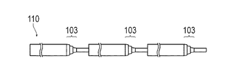
また、図9に示す他の変形例としての芯線110のように、芯線110に形成される第1移行部103が、複数段で形成されてもよい。
Moreover, the
また、カテーテル用チューブ10の軸直交断面における断面形状は、円形でなくてもよく、例えば楕円形等であってもよい。また、カテーテル用チューブ10内のルーメン14は、軸直交断面における断面形状が円形でなくてもよく、例えば、楕円形や半円形等であってもよい。また、カテーテル用チューブ10は、ルーメンが複数設けられてもよい。
The cross-sectional shape of the
1 カテーテル、
10 カテーテル用チューブ、
40,80,90,110 芯線、
41,81,91 太径部、
42,82,92 細径部、
43,83,93,103 第1移行部、
44,84 第2移行部、
51 内層被覆体(被覆体)、
52 補強体、
53 外層被覆体、
54 親水性被覆体、
60 管状連続体、
61 単体チューブ、
63 第1切断部、
64 第2切断部、
65 カテーテル用チューブの連続体、
X1 第1移行部の傾斜角、
X2 第2移行部の傾斜角。
1 catheter,
10 Catheter tube,
40, 80, 90, 110 core wires,
41, 81, 91 Large diameter part,
42, 82, 92 Small diameter part,
43, 83, 93, 103 first transition part,
44, 8 4 2nd transition part,
51 Inner layer covering (covering body),
52 reinforcements,
53 outer layer covering,
54 hydrophilic covering,
60 tubular continuum,
61 Single tube,
63 1st cutting part,
64 second cutting part,
65 A continuum of catheter tubes,
X1 tilt angle of the first transition part,
X2 The inclination angle of the second transition part.
Claims (7)
前記被覆体形成工程よりも後に、前記芯線上に得られる管状連続体を前記太径部および細径部の所定の位置で前記芯線とともに切断して複数の単体チューブを切り出す切断工程と、
前記単体チューブから前記芯線を除去する芯線除去工程と、を有するカテーテル用チューブの製造方法。 A large-diameter portion and a small-diameter portion having different outer diameters, a first transition portion provided on one end side of the large-diameter portion and reduced in diameter from the large-diameter portion to the small-diameter portion, and the large-diameter portion of the second transition portion inclination angle relative to the axis is large rather 90 degrees than the first transition portion with provided on the other end side is formed by a reduced diameter to another diameter portion from said large diameter portion A unit structure provided with a covering body forming step of forming a covering body by coating a resin on a core wire continuously formed at a predetermined interval in advance;
A cutting step of cutting a plurality of single tubes by cutting the tubular continuous body obtained on the core wire together with the core wire at a predetermined position of the large diameter portion and the small diameter portion after the covering body forming step;
And a core wire removing step of removing the core wire from the single tube.
外径の異なる太径部および細径部、前記太径部の一端側に設けられて前記太径部から前記細径部まで縮径して形成される第1移行部、並びに前記太径部の他端側に設けられて前記太径部から他の細径部まで縮径して形成されるとともに軸線に対する傾斜角が前記第1移行部よりも大きく90度である第2移行部を備える単位構造が、予め所定の間隔で連続的に形成された芯線と、
前記芯線上に樹脂を被覆して形成された被覆体と、を有するカテーテル用チューブの連続体。 A single tube that is an intermediate body of a catheter tube is a continuous body of catheter tubes in which a plurality of continuous tubes are formed on the same core wire,
A large-diameter portion and a small-diameter portion having different outer diameters, a first transition portion provided on one end side of the large-diameter portion and reduced in diameter from the large-diameter portion to the small-diameter portion, and the large-diameter portion of the second transition portion inclination angle relative to the axis is large rather 90 degrees than the first transition portion with provided on the other end side is formed by a reduced diameter to another diameter portion from said large diameter portion The core structure provided with a core wire continuously formed at a predetermined interval in advance,
A continuous body of a catheter tube having a covering formed by coating a resin on the core wire.
外径の異なる太径部および細径部、前記太径部の一端側に設けられて前記太径部から前記細径部まで縮径して形成される第1移行部、並びに前記太径部の他端側に設けられて前記太径部から他の細径部まで縮径して形成されるとともに軸線に対する傾斜角が前記第1移行部よりも大きく90度である第2移行部を備える単位構造が、予め所定の間隔で連続的に形成された芯線。 A core wire for manufacturing a catheter tube that is continuously formed by coating a single tube that is an intermediate body of a catheter tube,
A large-diameter portion and a small-diameter portion having different outer diameters, a first transition portion provided on one end side of the large-diameter portion and reduced in diameter from the large-diameter portion to the small-diameter portion, and the large-diameter portion of the second transition portion inclination angle relative to the axis is large rather 90 degrees than the first transition portion with provided on the other end side is formed by a reduced diameter to another diameter portion from said large diameter portion The core wire in which the unit structure provided is continuously formed in advance at a predetermined interval.
Priority Applications (1)
| Application Number | Priority Date | Filing Date | Title |
|---|---|---|---|
| JP2012254618A JP6088809B2 (en) | 2012-11-20 | 2012-11-20 | CATHETER TUBE MANUFACTURING METHOD, CATHETER TUBE CONTINUOUS AND CATHETER TUBE PRODUCING CORE |
Applications Claiming Priority (1)
| Application Number | Priority Date | Filing Date | Title |
|---|---|---|---|
| JP2012254618A JP6088809B2 (en) | 2012-11-20 | 2012-11-20 | CATHETER TUBE MANUFACTURING METHOD, CATHETER TUBE CONTINUOUS AND CATHETER TUBE PRODUCING CORE |
Publications (2)
| Publication Number | Publication Date |
|---|---|
| JP2014100325A JP2014100325A (en) | 2014-06-05 |
| JP6088809B2 true JP6088809B2 (en) | 2017-03-01 |
Family
ID=51023450
Family Applications (1)
| Application Number | Title | Priority Date | Filing Date |
|---|---|---|---|
| JP2012254618A Active JP6088809B2 (en) | 2012-11-20 | 2012-11-20 | CATHETER TUBE MANUFACTURING METHOD, CATHETER TUBE CONTINUOUS AND CATHETER TUBE PRODUCING CORE |
Country Status (1)
| Country | Link |
|---|---|
| JP (1) | JP6088809B2 (en) |
Cited By (2)
| Publication number | Priority date | Publication date | Assignee | Title |
|---|---|---|---|---|
| US9657607B2 (en) | 2014-09-03 | 2017-05-23 | GT Technologies | Rocker arm assembly and valvetrain assembly incorporating the same |
| US9863291B2 (en) | 2015-05-14 | 2018-01-09 | GT Technologies | Locator for use in a valvetrain of a cylinder head of an internal combustion engine |
Family Cites Families (8)
| Publication number | Priority date | Publication date | Assignee | Title |
|---|---|---|---|---|
| FR2759483B1 (en) * | 1997-02-12 | 1999-04-30 | Zircotube | METHOD OF MANUFACTURING A TUBE-GUIDE OF A FUEL ASSEMBLY OF A NUCLEAR REACTOR, MANDRE FOR FORGING A TUBE-GUIDE AND TUBE-GUIDE OBTAINED |
| JP2000262626A (en) * | 1999-03-17 | 2000-09-26 | Hitachi Cable Ltd | Catheter tube and its production |
| JP2006218085A (en) * | 2005-02-10 | 2006-08-24 | Kaneka Corp | Medical catheter tube and its manufacturing method |
| JP5080094B2 (en) * | 2007-01-30 | 2012-11-21 | 平河ヒューテック株式会社 | Continuation of catheter tube and method for manufacturing catheter tube |
| JP4796534B2 (en) * | 2007-04-18 | 2011-10-19 | 平河ヒューテック株式会社 | Method for manufacturing catheter tube |
| JP2014100339A (en) * | 2012-11-20 | 2014-06-05 | Terumo Corp | Catheter tube manufacturing method and continuous body of catheter tubes |
| JP6124563B2 (en) * | 2012-11-20 | 2017-05-10 | テルモ株式会社 | Catheter tube manufacturing method and catheter tube continuum |
| JP2014100336A (en) * | 2012-11-20 | 2014-06-05 | Terumo Corp | Catheter tube manufacturing method and continuous body of catheter tubes |
-
2012
- 2012-11-20 JP JP2012254618A patent/JP6088809B2/en active Active
Cited By (2)
| Publication number | Priority date | Publication date | Assignee | Title |
|---|---|---|---|---|
| US9657607B2 (en) | 2014-09-03 | 2017-05-23 | GT Technologies | Rocker arm assembly and valvetrain assembly incorporating the same |
| US9863291B2 (en) | 2015-05-14 | 2018-01-09 | GT Technologies | Locator for use in a valvetrain of a cylinder head of an internal combustion engine |
Also Published As
| Publication number | Publication date |
|---|---|
| JP2014100325A (en) | 2014-06-05 |
Similar Documents
| Publication | Publication Date | Title |
|---|---|---|
| JP2014100339A (en) | Catheter tube manufacturing method and continuous body of catheter tubes | |
| US11850375B2 (en) | Catheter devices and methods for making them | |
| US10065015B2 (en) | Catheter devices and methods for making them | |
| US11951262B2 (en) | Catheter devices and methods for making them | |
| WO2017104465A1 (en) | Catheter and method of manufacturing same | |
| JP6088809B2 (en) | CATHETER TUBE MANUFACTURING METHOD, CATHETER TUBE CONTINUOUS AND CATHETER TUBE PRODUCING CORE | |
| JP6124563B2 (en) | Catheter tube manufacturing method and catheter tube continuum | |
| JP2008307093A (en) | Catheter and its manufacturing method | |
| JP2014100323A (en) | Catheter tube manufacturing method | |
| JP2014100327A (en) | Catheter tube manufacturing method | |
| JP2014100321A (en) | Method for manufacturing catheter tube | |
| JP2014100330A (en) | Catheter tube manufacturing method | |
| JP2014100333A (en) | Catheter tube manufacturing method, continuous body of catheter tubes, and core wire for manufacturing catheter tubes | |
| JP2014100336A (en) | Catheter tube manufacturing method and continuous body of catheter tubes | |
| JP2014100328A (en) | Catheter tube manufacturing method | |
| JP2014100332A (en) | Catheter tube manufacturing method, continuous body of catheter tubes, and core wire for manufacturing catheter tubes | |
| JP2014100335A (en) | Catheter tube manufacturing method | |
| JP2014100329A (en) | Catheter tube manufacturing method | |
| JP2014100326A (en) | Catheter tube manufacturing method | |
| JP2014100337A (en) | Catheter tube manufacturing method | |
| JP2014100338A (en) | Catheter tube manufacturing method and continuous body of catheter tubes | |
| JP2014100324A (en) | Catheter tube manufacturing method and continuous body of catheter tubes | |
| JP2014100331A (en) | Catheter tube manufacturing method | |
| JP2023137533A (en) | Catheter and manufacturing method of tubular shaft | |
| JP6526998B2 (en) | CATHETER, AND METHOD FOR MANUFACTURING CATHETER |
Legal Events
| Date | Code | Title | Description |
|---|---|---|---|
| A621 | Written request for application examination |
Free format text: JAPANESE INTERMEDIATE CODE: A621 Effective date: 20151006 |
|
| A977 | Report on retrieval |
Free format text: JAPANESE INTERMEDIATE CODE: A971007 Effective date: 20160829 |
|
| A131 | Notification of reasons for refusal |
Free format text: JAPANESE INTERMEDIATE CODE: A131 Effective date: 20160905 |
|
| A521 | Request for written amendment filed |
Free format text: JAPANESE INTERMEDIATE CODE: A523 Effective date: 20161028 |
|
| TRDD | Decision of grant or rejection written | ||
| A01 | Written decision to grant a patent or to grant a registration (utility model) |
Free format text: JAPANESE INTERMEDIATE CODE: A01 Effective date: 20170123 |
|
| A61 | First payment of annual fees (during grant procedure) |
Free format text: JAPANESE INTERMEDIATE CODE: A61 Effective date: 20170206 |
|
| R150 | Certificate of patent or registration of utility model |
Ref document number: 6088809 Country of ref document: JP Free format text: JAPANESE INTERMEDIATE CODE: R150 |
|
| R250 | Receipt of annual fees |
Free format text: JAPANESE INTERMEDIATE CODE: R250 |
|
| R250 | Receipt of annual fees |
Free format text: JAPANESE INTERMEDIATE CODE: R250 |
|
| R250 | Receipt of annual fees |
Free format text: JAPANESE INTERMEDIATE CODE: R250 |
|
| R250 | Receipt of annual fees |
Free format text: JAPANESE INTERMEDIATE CODE: R250 |
|
| R250 | Receipt of annual fees |
Free format text: JAPANESE INTERMEDIATE CODE: R250 |