EP3885625A1 - Wellrohrverbindungsanordnung - Google Patents
Wellrohrverbindungsanordnung Download PDFInfo
- Publication number
- EP3885625A1 EP3885625A1 EP21162035.6A EP21162035A EP3885625A1 EP 3885625 A1 EP3885625 A1 EP 3885625A1 EP 21162035 A EP21162035 A EP 21162035A EP 3885625 A1 EP3885625 A1 EP 3885625A1
- Authority
- EP
- European Patent Office
- Prior art keywords
- mandrel
- holding
- corrugated pipe
- diameter
- shaft
- Prior art date
- Legal status (The legal status is an assumption and is not a legal conclusion. Google has not performed a legal analysis and makes no representation as to the accuracy of the status listed.)
- Granted
Links
Images


Classifications
-
- F—MECHANICAL ENGINEERING; LIGHTING; HEATING; WEAPONS; BLASTING
- F16—ENGINEERING ELEMENTS AND UNITS; GENERAL MEASURES FOR PRODUCING AND MAINTAINING EFFECTIVE FUNCTIONING OF MACHINES OR INSTALLATIONS; THERMAL INSULATION IN GENERAL
- F16L—PIPES; JOINTS OR FITTINGS FOR PIPES; SUPPORTS FOR PIPES, CABLES OR PROTECTIVE TUBING; MEANS FOR THERMAL INSULATION IN GENERAL
- F16L25/00—Construction or details of pipe joints not provided for in, or of interest apart from, groups F16L13/00 - F16L23/00
- F16L25/0036—Joints for corrugated pipes
- F16L25/0045—Joints for corrugated pipes of the quick-acting type
-
- F—MECHANICAL ENGINEERING; LIGHTING; HEATING; WEAPONS; BLASTING
- F16—ENGINEERING ELEMENTS AND UNITS; GENERAL MEASURES FOR PRODUCING AND MAINTAINING EFFECTIVE FUNCTIONING OF MACHINES OR INSTALLATIONS; THERMAL INSULATION IN GENERAL
- F16L—PIPES; JOINTS OR FITTINGS FOR PIPES; SUPPORTS FOR PIPES, CABLES OR PROTECTIVE TUBING; MEANS FOR THERMAL INSULATION IN GENERAL
- F16L25/00—Construction or details of pipe joints not provided for in, or of interest apart from, groups F16L13/00 - F16L23/00
- F16L25/0036—Joints for corrugated pipes
-
- F—MECHANICAL ENGINEERING; LIGHTING; HEATING; WEAPONS; BLASTING
- F16—ENGINEERING ELEMENTS AND UNITS; GENERAL MEASURES FOR PRODUCING AND MAINTAINING EFFECTIVE FUNCTIONING OF MACHINES OR INSTALLATIONS; THERMAL INSULATION IN GENERAL
- F16L—PIPES; JOINTS OR FITTINGS FOR PIPES; SUPPORTS FOR PIPES, CABLES OR PROTECTIVE TUBING; MEANS FOR THERMAL INSULATION IN GENERAL
- F16L33/00—Arrangements for connecting hoses to rigid members; Rigid hose-connectors, i.e. single members engaging both hoses
- F16L33/30—Arrangements for connecting hoses to rigid members; Rigid hose-connectors, i.e. single members engaging both hoses comprising parts inside the hoses only
Definitions
- the invention relates to a connection arrangement with a one-piece connector part and a corrugated tube fluidically connected to the connector part.
- the connector part has a through-channel which extends along a central axis and which opens on one side to the connector part in a mandrel molded onto the connector part.
- the mandrel has a holding area and a sealing area, with at least two holding elements being arranged axially to the central axis adjacent to one another in the holding area.
- the corrugated tube is plugged onto the mandrel with a corrugated plug-on section in a plug-on direction and is arranged in the holding area and the sealing area of the mandrel and fluidically connected to the through-channel of the connector part.
- connection arrangements are used in particular in motor vehicles, since corrugated pipes are characterized by preferred flexibility properties, in particular in areas of application with high levels of vibration.
- connection arrangements which have a multi-part connector part, so that the corrugated tubes are braced radially between two elements of the connector part.
- This has the disadvantage that the individual elements have to be adapted to the corrugated contour, which is complex and expensive, and the assembly requires a large amount of installation space, assembly effort and often special tools.
- corrugated pipes which have an edged wall so that the corrugated pipe wall runs perpendicular to the pipe duct or parallel to the pipe duct, but does not have an undulating course, also called sinusoidal.
- the canted wall stiffens the corrugated pipe radially and axially to the pipe duct and thereby reduces the flexibility of the corrugated pipe.
- folded walls are not so strong against radial loads.
- connection arrangement for coolant systems with corrugated pipes, in which the corrugated pipe is to be spiked onto a connecting piece of a connecting element with formed holding elements.
- the holding elements are designed as holding teeth axially adjacent to one another in accordance with a Christmas tree profile and fulfill both a sealing function and a holding function.
- a corrugated end of the corrugated pipe is compressed over a slip-on length, as a result of which the corrugated pipe is arranged radially stiffened in the compressed section on the connecting piece.
- This connection arrangement is particularly advantageous in the manufacture of the connection element and the assembly of the corrugated pipe due to the one-piece connection element.
- the connection arrangement requires little installation space and is therefore well suited for use in narrow and difficult-to-reach areas of use.
- connection arrangement a distance between wave troughs and wave crests of the corrugated pipe is massively shortened over the plug-on length due to the upsetting.
- the disadvantage of this is that the peaks of the wave troughs and crests can lead to heavy loads and even breakage.
- the corrugated pipeline is under axial tension due to the upsetting, whereby the corrugated pipe always tends to form back, which leads to a loosening of the corrugated pipeline and at the same time worsens the tightness and the holding effect. Both effects, both the risk of breakage and the tension due to the compression, lead to a shortened service life of the connection arrangement.
- connection arrangement is also very difficult to dismantle due to the retaining teeth used, which are arranged in the manner of a Christmas tree, since a non-destructive detachment of the corrugated pipe is difficult or impossible.
- the retaining teeth dig into an inner jacket of the corrugated pipe, which can be peeled off and permanently damaged, or the retaining teeth dig so deep that the corrugated pipe tears off or is cut off.
- the invention is based on the object of providing a connection arrangement which has a longer service life, in particular lower loads and stresses on the corrugated pipe, in particular while at least maintaining the advantageous properties of the known connection arrangement with regard to installation space, manufacture and assembly.
- the holding area and the sealing area are arranged one behind the other axially to the central axis.
- the mandrel has a smooth surface facing the corrugated pipe, which surface has a larger outside diameter facing the corrugated pipe than an inside diameter of a corrugated trough of the corrugated pipe facing the mandrel.
- At least one holding element is designed as a shaft element of the mandrel, in particular a fully circumferential shaft element, which at a shaft maximum of the shaft element has a larger outer diameter pointing toward the corrugated pipe than the inner diameter of the corrugated trough of the corrugated pipe.
- a connection arrangement which is particularly well suited for sinusoidal corrugated pipes due to its wave-shaped holding element.
- the axially arranged separation of the sealing area and the holding area has the consequence that the corrugated pipe in the sealing area and the holding area can be expanded radially and axially in different ways, in particular independently of the respective other area.
- the holding element has the effect that the corrugated pipe does not become detached from the mandrel against the direction of attachment.
- the purpose of the sealing area is to ensure that the corrugated pipe with a corrugation trough does not lift off the mandrel and that a leak occurs because the mandrel radially expands the corrugated pipe in the sealing area.
- the bearing surface of the corrugated troughs of the corrugated pipe on the mandrel in the sealing area is minimal, so that a contact pressure on the bearing surface increases the sealing effect.
- corrugated pipe does not detach from the mandrel until a release force is reached against the direction of attachment.
- “does not release” does not preclude a non-destructive release of the corrugated pipe from the mandrel when the release force is reached.
- the corrugated pipe is designed to be radially elastically expandable in a known manner, the corrugated pipe preferably being radially expanded in the elastic range when the corrugated pipe is arranged on the mandrel.
- a radial restoring force acts against the radial expansion caused by the mandrel.
- B. depends on the ambient temperature and the corrugated pipe is sealingly arranged on the mandrel.
- the shaft element of the mandrel is that the corrugated pipe with its slip-on section can be more easily attached to the mandrel due to the wave shape, the shaft element of the mandrel advantageously lying between two wave troughs of the corrugated pipe and one at the wave maximum generates axial resistance to movement of the corrugated tube axially to the central axis.
- the shaft element of the mandrel has an insertion bevel.
- the lead-in bevel increases the outside diameter of the mandrel in the direction of attachment to the outside diameter at the shaft maximum.
- the shaft element of the mandrel additionally or alternatively has a holding bevel which reduces the outer diameter from the shaft maximum in the attachment direction to a holding diameter.
- the bevels have the advantage that they represent a compromise between an assembly effort and a disassembly effort, in that the necessary insertion and release forces can be adapted by the respective gradients.
- the lead-in bevel in the plug-on direction is preferably designed to be flatter towards the shaft maximum of the shaft element of the mandrel than the holding bevel against the plug-on direction to the shaft maximum.
- a release force to be expended against the plug-on direction to detach the corrugated pipe from the plug connector is expediently greater than a plug-in force to be used in the plug-on direction to plug on the corrugated pipe.
- At least the holding bevel in a contact area for the corrugated trough of the corrugated pipe is designed in an arc shape with a holding radius rising against the direction of attachment to the corrugation maximum.
- sinusoidal corrugated pipes can easily rest against the holding bevel, which is arcuate with a holding radius, and can be deformed to abut the holding bevel over a large area in the event of an axial load against the direction of attachment.
- the corrugated pipe is expediently held by such a wave element due to the large contact surface at least partially, in particular largely, by a frictional force on the mandrel against the direction of attachment. In particular, this further reduces the need for sharp-edged retaining teeth or makes sharp-edged retaining teeth unnecessary.
- the advantageous effect of the shaft element of the mandrel with the holding radius can also be advantageously implemented in a practical form of the invention in that the holding radius of the arcuate holding bevel corresponds to a wave radius of an inner jacket section of the corrugated pipe in the region of the wave trough.
- the holding bevel is designed to be adapted to the inner jacket section of the corrugated pipe in such a way that, without the corrugated valley being pressed against the holding bevel, ie. H. already in an unloaded state, the corrugated pipe rests extensively on the arcuate retaining slope.
- a friction surface and thereby the axial resistance or the necessary release force against the direction of attachment is increased.
- the mandrel expediently has an outer jacket surface which, at least in the area of the holding bevel, preferably has a holding structure.
- the holding structure increases the frictional force at least against the direction of attachment between the corrugated pipe and the mandrel or the shaft element.
- a retaining element is expediently designed as a retaining tooth that is particularly full around the central axis.
- the retaining tooth has a slip-on bevel, which preferably increases the outer diameter of the mandrel in the slip-on direction to a clamping diameter.
- the retaining tooth preferably has a clamping edge pointing in the attachment direction. The retaining tooth advantageously blocks the wave trough against the direction of attachment, at least in a form-fitting or non-positive manner. The clamping edge thereby increases the releasing force to be overcome for releasing the corrugated pipe from the mandrel.
- the clamping edge is designed as a cutting edge, as a result of which the retaining tooth complements the shaft element of the mandrel in that it increases the necessary release force by means of its clamping edge or cutting edge.
- the cutting edge prevents the corrugated pipe from becoming detached from the mandrel against the direction of attachment.
- the clamping diameter of the mandrel corresponds at least to the outer diameter at the shaft maximum of the shaft element of the mandrel. Furthermore, it is expedient if the outer diameter of the mandrel corresponds to the holding diameter immediately behind the clamping edge or the cutting edge in the attachment direction.
- the clamping edge or the cutting edge is designed as an abrupt change from the clamping diameter to a smaller diameter of the mandrel, in particular the holding diameter.
- connection arrangement has proven to be advantageous for a particularly favorable and efficient production of the connection arrangement.
- the connector part can be improved in terms of manufacture in that the connector part is monolithically formed in one piece. It has also proven to be advantageous if the connector part is formed from a thermoplastic material.
- connection arrangement 1 has a one-piece connector part 2 and a corrugated tube 4 that is fluidically connected to the connector part 2.
- the corrugated pipe 4 is in particular a sinusoidal corrugated pipe 4 in accordance with the Figures 1 and 2 , which is advantageously flexible, compressible and resistant to radial influences.
- the connector part 2 has a through-channel (not shown) that extends along a central axis X.
- the passage channel opens on one side to the connector part 2, as in the Figures 1 and 2 shown, in an outlet opening 6 of a mandrel 8 molded onto the connector part 2.
- the mandrel 8 preferably has an opening area 10, the outer diameter of the mandrel 8 in the opening area 10 at the outlet opening 6 preferably being smaller than the smallest inner diameter of the corrugated tube 4.
- the mandrel 8 has a holding area 12 and a sealing area 14, wherein in the holding area 12 at least two holding elements are arranged axially adjacent to one another in relation to the central axis X.
- the sealing area 14 preferably directly adjoins the mouth area 10.
- the corrugated pipe 4 is pushed onto the mandrel 8 with a corrugated plug-on section in a plug-on direction A.
- the corrugated tube 4 is expediently designed to be corrugated over its entire length.
- the corrugated pipe 4 has a corrugated pipe wall 16, an inner jacket 18 of the corrugated pipe 4 enclosing a pipeline channel 20.
- the corrugated pipe wall 16 has a course which always merges from a wave crest 22 into a wave trough 24, wherein in an unloaded and unplugged state, as in FIG Figure 3 shown, an inner diameter DT of the corrugated pipe 4 in the wave trough 24 is smaller than an inner diameter DB in a wave crest 22.
- the corrugated pipe 4 is arranged in the connecting arrangement 1 in the holding area 12 and the sealing area 14 of the mandrel 8, the corrugated pipe 4, according to the Figures 1 and 2 , is fluidically connected to the through-channel of the connector part 2.
- the corrugated pipe 4 is placed over the sealing area 14 on the mandrel 8 in such a way that, as described and in the Figures 1 and 2 shown, is arranged both in the sealing area 14 and in the holding area 12.
- the separation of the sealing area 14 and the holding area 12 has the consequence that the corrugated pipe 4 in the sealing area 14 and holding area 12 can be expanded radially and axially in a different way, in particular independently of the respective other area.
- the mandrel 8 has a smooth surface 26 facing the corrugated pipe 4 in the sealing area 14, which has a larger outer diameter DD facing the corrugated pipe 4 than an inner diameter DT of the corrugated pipe 4 in the corrugation trough 24 facing the mandrel 8.
- the surface 26 is of the mandrel 8 in the sealing area 14 running parallel to the central axis X. Because of a radial expansion of the corrugated pipe 4 in the sealing area 14, the sealing area 14 thus fulfills the purpose that the corrugated pipe 4 with at least one wave trough 24 does not lift off the mandrel 8 and a leak occurs.
- the corrugated tube 4 is expanded to the outer diameter DD of the mandrel 8 in the sealing area 14 via the mouth area 10, which preferably has a conical surface 28 which widens in diameter in the direction of attachment A and which faces the corrugated tube 4 .
- At least one holding element is designed as a shaft element 30 of the mandrel 8, in particular a fully circumferential, shaft element 30, which at a shaft maximum 32 of the shaft element 30 has a larger outer diameter DM facing the corrugated pipe 4 than the inner diameter DT of the corrugated pipe 4 in the corrugation trough 24
- the sealing area 14 of the mandrel 8 has the effect, by means of the shaft element 30 or the holding elements, that the corrugated pipe 4 does not detach from the mandrel 8 against the attachment direction A until a certain release force L acting against the attachment direction A is reached.
- the corrugated tube 4 can be separated from the mandrel 8 in a non-destructive manner when the release force L is reached or exceeded, counter to the attachment direction A.
- the shaft element 30 of the mandrel 8 Another advantage in the shaft element 30 of the mandrel 8 is that the corrugated tube 4 with its push-on section can be more easily attached to the mandrel 8 due to the wave shape, the shaft element 30 of the mandrel 8, as shown in FIGS Figures 1 and 2 shown, at the wave maximum 32 advantageously between two Wave troughs 24 and creates an axial resistance to movement of the corrugated tube 4 axially to the central axis X.
- Figure 1 shows an expedient embodiment, according to which at least two, in particular exactly two holding elements as shown, are designed as two shaft elements 30 of the mandrel 8, in particular completely circumferential to the central axis X.
- the shaft elements 30 of the mandrel each have a larger outer diameter DM facing the corrugated tube 4 at a corrugation maximum 32 of the respective corrugation element 30 than the inner diameter DT of the corrugated tube 4 in the corrugation valley 24.
- Figure 2 shows a preferred embodiment, wherein the at least one shaft element 30 of the mandrel 8 is combined with a differently designed holding element, whereby the advantageous properties of the different holding elements are combined.
- a connection arrangement 1 is advantageously provided which, due to a wave element 30 of the mandrel 8, is particularly advantageously suitable for sinusoidal corrugated pipes 4.
- the corrugated pipe 4 of the connecting arrangement 1 is designed to be radially elastically expandable, with the corrugated pipe 4 being stretched preferably in the elastic range when the corrugated pipe 4 is arranged on the mandrel 8.
- An expansion in the elastic range favors the multiple use of the connection arrangement 1 and enables non-destructive dismantling.
- a radial restoring force F which depends in particular on the geometry and the material of the corrugated pipe 4, but also on environmental influences, such as. B. depends on the ambient temperature and the corrugated tube 4 is sealingly arranged on the mandrel 8.
- the shaft element 30 of the mandrel 8 has a holding bevel 34, in particular corresponding to the Figures 1 and 2 .
- the holding bevel 34 reduces the outside diameter DM from the shaft maximum 32 in the attachment direction A to a holding diameter DH.
- the radial bracing of the corrugated pipe 4 in the holding area 12 can be adapted via the holding diameter DH.
- the holding diameter DH is preferably selected in such a way that the corrugated pipe 4 rests on the mandrel 8 with the holding diameter DH with at least one wave trough 24 in the event of an elastic recovery after the wave maximum 32.
- the shaft element 30 of the mandrel 8 expediently has an insertion bevel 36 which increases the outside diameter of the mandrel 8 in the attachment direction A to the outside diameter DM in the shaft maximum 32.
- the insertion bevels 36 By means of the insertion bevels 36, the outer diameter DM of the mandrel 8 in the shaft maximum 32 can be made larger radially to the central axis X, the insertion bevel 36 making it easier for the corrugated tube 4 to overcome the shaft maximum 32 and thus reducing the insertion force S to be applied.
- the outside diameter DM of the mandrel 8 in the shaft maximum 32 corresponds to the outside diameter DD in the sealing area 14, so that the shaft element 30 of the mandrel 8 is only formed by the holding bevel 34.
- the bevels 34, 36 have the advantageous property that they represent a compromise between an assembly effort and a disassembly effort, in that the insertion and release forces S, L to be applied can be adapted by the respective gradients. Furthermore, a version that has both a The lead-in bevel 36 and a retaining bevel 34 have the advantage that the shaft element 30 of the mandrel 8 is arranged at the shaft maximum 32 of the shaft element 30 between two shaft troughs 24 of the corrugated pipe 4 and protrudes further in the radial direction of a wave crest 22. The corrugated tube 4 is blocked or hindered to a greater extent against an axial movement to the central axis X.
- the arrangement of the wave maximum 32 of the wave element 30 in the area of a wave crest 22 is advantageous because the outer diameter DM of the mandrel 8 in the wave maximum 32 can be made larger.
- the relevant wave troughs 24 overcome the wave maximum 32 of the wave element 30 only once, with the corresponding Figures 1 and 2 in an attached position, the shaft element 30 of the mandrel 8 is located with its shaft maximum 32 of the shaft element 30 adjacent to a wave crest 22.
- the corrugated pipe 4 at the wave crest 22 has a larger inside diameter DB than in the wave trough 24.
- the corrugated pipe 4 is less stressed over its service life with a nonetheless high release resistance, which is ensured by the smaller inside diameter DT of the corrugated pipe 4 in the wave trough 24.
- the insertion bevel 36 in the insertion direction A is preferably designed to be flatter towards the shaft maximum 32 of the shaft element 30 than the holding bevel 34 against the insertion direction A to the shaft maximum 32 of the shaft element 30.
- This version is in the Figures 1 and 2 shown.
- the release force L to be used against the plug-on direction A to detach the corrugated pipe 4 from the connector part 2 is expediently greater than the plug-in force S to be used in the plug-on direction A to plug the corrugated pipe 4 on.
- At least the retaining bevel 34 in a contact area for the wave trough 24 of the corrugated pipe 4 is arcuate with a retaining radius 38 rising against the attachment direction A to the wave maximum 32 of the wave element 30.
- sinusoidal corrugated pipes 4 can easily become at least in the contact area on the holding bevel 34, which is arcuate in a holding radius 38, and deform to a large-area contact on the holding bevel 34 in the event of an axial load against the attachment direction A.
- the corrugated pipe 4 is expediently held by such a wave element 30 of the mandrel 8 due to the large contact surface at least partially, in particular largely, by a frictional force on the mandrel 8 against the attachment direction A.
- a pressing force is generated by the radial restoring force F due to the expansion of the corrugated pipe 4 or the corrugated valley 24.
- this embodiment further reduces the need for sharp-edged retaining teeth 40 or makes sharp-edged retaining teeth 40 unnecessary.
- the advantageous effect of the shaft element 30 with an arcuate retaining bevel 34 can also be demonstrated in an advantageous embodiment, as in FIGS Figures 1 and 2 shown, in that the holding radius 38 of the arcuate holding bevel 34 corresponds to a wave radius 42 of an inner jacket section 44 of the corrugated pipe 4 in the region of the wave trough 24.
- Such an advantageous embodiment has the advantage that the holding bevel 34 is adapted to the inner jacket section 44 of the corrugated pipe 4 in such a way that without the corrugated valley 24 being pressed against the holding bevel 34, the corrugated pipe 4 would rest over a large area on the holding bevel 34.
- the holding bevel 34 is therefore correspondingly in a non-attached state of the corrugated pipe 4 Figure 3 marked.
- a friction surface and thereby the axial resistance or the release force L to be applied against the attachment direction A is increased.
- the mandrel 8 expediently has an outer jacket surface 46 which, at least in the area of the holding bevel 34, preferably has a holding structure.
- the design of a retaining slope 34 with a retaining structure is not shown.
- the holding structure increases the frictional force at least against the plug-on direction A between the corrugated pipe 4 and the mandrel 8 or the shaft element 30 of the mandrel 8.
- This embodiment advantageously reduces the risk of the corrugated pipe 4 coming loose from the mandrel 8 against the plug-on direction A by reducing the release forces to be applied L. increase.
- Holding structures in the sense of this invention can be designed as a roughened surface structure, bumps or grooves.
- a retaining element is preferably designed as a retaining tooth 40, in particular a retaining tooth 40 that extends over the entire circumference of the central axis X .
- the retaining tooth 40 as in FIG Figure 2 shown, a slip-on bevel 48, which preferably increases the outer diameter of the mandrel 8 in the slip-on direction A to a clamping diameter DK.
- the retaining tooth 40 expediently has a clamping edge pointing in the attachment direction A, or, as in FIG Figure 2 shown, a cutting edge 50.
- the holding tooth 40 supplements the shaft element 30 and ensures an increased holding force and prevents the corrugated tube 4 from becoming detached from the mandrel 8 against the attachment direction A.
- the retaining tooth 40 advantageously blocks the wave trough 24 against the attachment direction A, at least in a form-fitting manner.
- the cutting edge 50 digs into the inner jacket 18 of the corrugated pipe 4, so that the corrugated pipe 4 does not become detached from the mandrel 8 against the direction of attachment A.
- the retaining tooth 40 and the shaft element 30 of the mandrel 8 work together synergistically in such a way that damage occurs in the inner jacket 18 of the corrugated pipe 4 as axially distanced as possible from the central axis X of the sealing area 14.
- Another synergetic effect has the effect that the retaining tooth 40 provides sufficient resistance to loosening against the direction of attachment A im Compared to known connection arrangements with only one or more retaining teeth 40, less material is removed from the corrugated pipe 4 and, in particular in the case of an embodiment with only one retaining tooth 40, this does not dig into the corrugated pipe wall 16 of the corrugated pipe 4 or only slightly.
- the clamping diameter DK of the mandrel 8 corresponds at least to the outside diameter DM of the corrugated tube 4 in the shaft maximum 32 of the shaft element 30. It is also useful if the outside diameter of the mandrel 8 corresponds to the holding diameter DH in the attachment direction A immediately behind the clamping edge or the cutting edge 50.
- the clamping edge or the cutting edge 50 is designed as an abrupt change from the clamping diameter DK to a smaller diameter of the mandrel 8, in particular the holding diameter DH.
- the holding diameter DH of the mandrel 8 is smaller than the outer diameter DD of the mandrel 8 in the sealing area 14.
- the corrugated tube 4 is less radially loaded in the holding area 12, which is possible due to the holding element 40 and the axially offset sealing area 14 that the radial tension is primarily required to maintain the necessary tightness.
- the loads in the holding area 12 do not add up to a critical level, as a result of which the service life is improved.
- a dimensioning is particularly preferred in which the outer diameter DM of the shaft element 30 of the mandrel 8 in the shaft maximum 32 of the shaft element 30 is greater than that in a range from 10% to 35%, in particular 15% to 30%, preferably 20% to 25% Inner diameter DT of the corrugated pipe 4 in the wave trough 24.
- the outer diameter DD of the mandrel 8 in the sealing area 14 is in a range of 5% to 30%, in particular 10% to 25%, preferably 15% to 20% larger than the inner diameter DT of the corrugated pipe 4 in the trough 24.
- the sealing properties of the connection arrangement 1 are improved in that the sealing area 14 has an axial extension 52 to the central axis X, which corresponds to at least a distance 54 measured axially to the pipeline channel 20 between two wave troughs 24 of the corrugated pipe 4.
- an axial distance in a, in Figure 3 shown, not plugged-on state and in particular not compressed state of the corrugated pipe 4 assumed.
- a particularly preferred embodiment is shown, according to which the sealing area 14 has an axial extension 52 to the central axis X, which corresponds to at least one and a half times a distance 54 between two corrugation troughs 24 of the corrugated pipe 4, which is axial to the pipeline channel 20.
- the simple distance 54 between two wave troughs 24 is preferably 4 mm, resulting in an extension 52 of the sealing area 14 of at least 4 mm, particularly preferably 6 mm, axially to the central axis X for the advantageous embodiment.
- connection arrangement 1 The use of sinusoidal corrugated tubes 4 has been found to be advantageous for a particularly favorable and efficient production of the connection arrangement 1.
- the connector part 2 can be improved in terms of production in that the connector part 2 is monolithically formed in one piece. as It has also been found to be advantageous if the connector part 2 is formed from a thermoplastic material.
- the invention is not limited to the illustrated and described exemplary embodiments, but rather also includes all embodiments that have the same effect within the meaning of the invention. It is expressly emphasized that the exemplary embodiments are not limited to all features in combination; rather, each individual sub-feature can also have an inventive significance in isolation from all other sub-features. Furthermore, the invention has not yet been limited to the combination of features defined in claim 1, but can also be defined by any other combination of specific features of all of the individual features disclosed. This means that in principle practically every individual feature of claim 1 can be omitted or replaced by at least one individual feature disclosed elsewhere in the application.
Landscapes
- Engineering & Computer Science (AREA)
- General Engineering & Computer Science (AREA)
- Mechanical Engineering (AREA)
- Joints That Cut Off Fluids, And Hose Joints (AREA)
- Moulds For Moulding Plastics Or The Like (AREA)
- Rigid Pipes And Flexible Pipes (AREA)
Abstract
Description
- Die Erfindung betrifft eine Verbindungsanordnung mit einem einstückigen Verbinderteil und einem fluidisch mit dem Verbinderteil verbundenen Wellrohr. Hierbei weist das Verbinderteil einen sich entlang einer Mittelachse erstreckenden Durchgangskanal auf, welcher einseitig zu dem Verbinderteil in einem an dem Verbinderteil angeformten Dorn mündet. Dabei weist der Dorn einen Haltebereich und einen Dichtbereich auf, wobei im Haltebereich mindestens zwei Halteelemente axial zur Mittelachse benachbart zueinander angeordnet sind. Das Wellrohr ist mit einem gewellten Aufsteckabschnitt in eine Aufsteckrichtung auf dem Dorn aufgesteckt und in dem Haltebereich und dem Dichtbereich des Dorns angeordnet und fluidisch mit dem Durchgangskanal des Verbinderteils verbunden.
- Derartige Verbindungsanordnungen werden insbesondere in Kraftfahrzeugen verwendet, da Wellrohre sich durch bevorzugte Flexibilitätseigenschaften, insbesondere an schwingungsintensiven Einsatzgebieten, auszeichnen.
- Oftmals werden derartige Verbindungsanordnungen verwendet, welche ein mehrteiliges Verbinderteil aufweisen, so dass die Wellrohre radial zwischen zwei Elementen des Verbinderteils verspannt werden. Das hat den Nachteil, dass die einzelnen Elemente an die Wellkontur angepasst werden müssen, was aufwändig und teuer ist, und die Montage einen großen Bauraum, Montageaufwand und oftmals Spezialwerkzeuge benötigt. Weiterhin ist es bekannt, das Ende eines Wellrohres als ein Glattrohr zu fertigen, so dass die Rohre eine größere Auflagefläche auf dem Verbinderteil haben. Das verringert die Herstellungskosten des Verbinderteils, erfordert jedoch abgemessene, zugeschnittene Wellrohre und in den Endbereichen angepasste Wellrohre, was die Kosten, die Vielseitigkeit und die Anpassungsfähigkeit der Wellrohre einschränkt.
- Weiterhin ist es bekannt, Wellrohre zu verwenden, welche eine gekantete Wandung aufweisen, so dass die Wellrohrwandung senkrecht zum Rohrleitungskanal oder parallel zum Rohrleitungskanal verläuft, aber keinen wellenförmigen Verlauf, auch sinusförmig genannt, aufweist. Die gekantete Wandung versteift dabei das Wellrohr radial und axial zum Rohrleitungskanal und verringert dadurch die Flexibilität des Wellrohrs. Weiterhin sind gekantete Wandungen nicht so tragfähig gegenüber radialen Lasten.
- Es ist beispielsweise aus der
DE 10 2015 120 508 A1 bekannt, für Kühlmittelsysteme mit Wellrohren eine gattungsgemäße Verbindungsanordnung zu verwenden, bei welcher das Wellrohr auf einen Anschlussstutzen eines Verbindungselements mit ausgebildeten Halteelementen aufzudornen ist. Dabei sind die Halteelemente entsprechend einem Tannenbaumprofil axial benachbart zueinander als Haltezähne ausgebildet und erfüllen sowohl eine Dichtfunktion als auch eine Haltefunktion. Beim Aufdornen wird ein gewelltes Ende des Wellrohrs über eine Aufstecklänge gestaucht, wodurch das Wellrohr im gestauchten Abschnitt radial versteift auf dem Anschlussstutzen angeordnet ist. Diese Verbindungsanordnung zeichnet sich dabei auf Grund des einstückig ausgebildeten Verbindungselements besonders vorteilhaft in der Herstellung des Verbindungselements und der Montage des Wellrohrs aus. Weiterhin benötigt die Verbindungsanordnung einen geringen Bauraum und eignet sich daher gut für den Einsatz in engen und schwer zu erreichenden Einsatzgebieten. - Bei der genannten Verbindungsanordnung ist ein Abstand von Wellentälern und Wellenbergen des Wellrohrs über die Aufstecklänge durch die Stauchung massiv verkürzt. Dies hat nachteilig zur Folge, dass es in den Spitzen der Wellentäler und Wellenbergen zu starken Belastungen bis hin zum Bruch kommen kann. Weiterhin steht die Wellrohrleitung auf Grund der Stauchung unter einer axialen Spannung, wodurch das Wellrohr stets dazu neigt, sich zurückzuformen, was zu einem Lösen der Wellrohrleitung führt und die Dichtigkeit und die Haltewirkung gleichzeitig verschlechtert. Beide Effekte, sowohl die Bruchgefahr als auch die Verspannung durch die Stauchung, führen zu einer verkürzten Standzeit der Verbindungsanordnung. Ebenfalls ist diese Verbindungsanordnung auf Grund der verwendeten, tannenbaumartig angeordneten Haltezähne sehr schwer demontierbar, da ein zerstörungsfreies Lösen des Wellrohrs schwer bis nicht möglich ist. Bei der Bewegung des Wellrohrs gegen die Aufsteckrichtung graben sich die Haltezähne in einen Innenmantel des Wellrohrs ein, dabei kann dieser abgeschält und nachhaltig beschädigt werden, oder die Haltezähne graben sich so tief ein, dass das Wellrohr abreißt oder abgeschnitten wird.
- Der Erfindung liegt die Aufgabe zugrunde, eine Verbindungsanordnung bereitzustellen, welche insbesondere bei zumindest der Beibehaltung der vorteilhaften Eigenschaften der bekannten Verbindungsanordnung hinsichtlich Bauraum, Herstellung und Montage eine längere Standzeit, insbesondere geringere Belastungen und Spannungen des Wellrohrs aufweist.
- Die Aufgabe wird erfindungsgemäß durch die Merkmale des Anspruchs 1 dadurch gelöst, dass der Haltebereich und der Dichtbereich axial zu der Mittelachse hintereinander angeordnet sind. Der Dorn hat im Dichtbereich eine glatte, zum Wellrohr weisende Oberfläche ausgebildet, welche einen größeren, zum Wellrohr weisenden Außendurchmesser aufweist als ein zum Dorn weisender Innendurchmesser eines Wellentals des Wellrohrs. Zumindest ein Halteelement ist als ein zu der Mittelachse, insbesondere vollumfängliches, Wellenelement des Dorns ausgebildet, welches an einem Wellenmaximum des Wellenelementes einen größeren, zum Wellrohr weisenden Außendurchmesser aufweist als der Innendurchmesser des Wellentals des Wellrohrs.
- Mit der erfindungsgemäßen Ausführung wird eine Verbindungsanordnung bereitgestellt, welche auf Grund ihres wellenförmigen Halteelements besonders gut für sinusförmige Wellrohre geeignet ist. Weiterhin hat die axial angeordnete Trennung von Dichtbereich und Haltebereich zur Folge, dass das Wellrohr im Dichtbereich und Haltebereich unterschiedlich, insbesondere unabhängig vom jeweils anderen Bereich, radial gedehnt und axial gehalten werden kann. In dem Haltebereich hat das Halteelement die Wirkung, dass sich das Wellrohr nicht gegen die Aufsteckrichtung von dem Dorn löst. Der Dichtbereich erfüllt den Zweck, dass sich das Wellrohr mit einem Wellental nicht von dem Dorn abhebt und eine Leckage entsteht, indem der Dorn im Dichtbereich das Wellrohr radial aufdehnt. Zudem ist die Auflagefläche der Wellentäler des Wellrohrs auf den Dorn im Dichtbereich minimal, so dass ein Anpressdruck an der Auflagefläche die Dichtungswirkung verstärkt.
- Dass sich das Wellrohr vom Dorn "nicht löst", bedeutet im Sinne der Erfindung insbesondere, dass sich das Wellrohr bis zu einem Erreichen einer Lösekraft gegen die Aufsteckrichtung nicht von dem Dorn löst. Insbesondere schließt "nicht löst" ein zerstörungsfreies Lösen des Wellrohrs vom Dorn beim Erreichen der Lösekraft nicht aus.
- Zu diesem Zweck ist das Wellrohr in bekannter Art radial elastisch dehnbar ausgebildet, wobei beim Anordnen des Wellrohrs auf dem Dorn das Wellrohr vorzugsweise im elastischen Bereich radial gedehnt wird. Gegen die radiale Dehnung durch den Dorn wirkt eine radiale Rückstellkraft, welche insbesondere von Geometrie und Werkstoff, aber auch von Umwelteinflüssen, wie z. B. der Umgebungstemperatur abhängig ist und das Wellrohr dichtend auf dem Dorn anordnet.
- Auf Grund der axialen Trennung auf dem Dorn zwischen dem Dichtbereich und dem Haltebereich ist eine Überlagerung zwischen radialen und axialen Spannungen verringert, wodurch das Wellrohr für eine vorteilhafte Dichtungseigenschaft geringfügiger radial gedehnt, bzw. für eine ausreichende axiale Haltekraft geringfügiger axial blockiert und/oder radial verspannt werden muss.
- Ein weiterer Vorteil besteht im Wellenelement des Dorns darin, dass durch die Wellenform das Wellrohr mit seinem Aufsteckabschnitt leichter auf den Dorn aufgesteckt werden kann, wobei sich das Wellenelement des Dorns am Wellenmaximum vorteilhaft zwischen zwei Wellentäler des Wellrohrs legt und einen axialen Widerstand gegen eine Bewegung des Wellrohrs axial zu der Mittelachse erzeugt.
- In einer vorteilhaften Ausführungsform der Erfindung weist das Wellenelement des Dorns eine Einführschräge auf. Die Einführschräge vergrößert den Außendurchmesser des Dorns in Aufsteckrichtung auf den Außendurchmesser im Wellenmaximum. Vorzugsweise weist das Wellenelement des Dorns zusätzlich oder alternativ eine Halteschräge auf, welche den Außendurchmesser von dem Wellenmaximum in Aufsteckrichtung auf einen Haltedurchmesser verringert. Die Schrägen haben den Vorteil, dass sie einen Kompromiss zwischen einem Montageaufwand und einem Demontageaufwand darstellen, indem notwendige Steck- und Lösekräfte durch die jeweiligen Steigungen angepasst werden können.
- In diesem Sinne ist in einer bevorzugten Variante die Einführschräge in Aufsteckrichtung vorzugsweise flacher zum Wellenmaximum des Wellenelementes des Dorns ansteigend ausgebildet als die Halteschräge gegen die Aufsteckrichtung zu dem Wellenmaximum. Zweckmäßig ist dadurch eine aufzuwendende Lösekraft gegen die Aufsteckrichtung zum Lösen des Wellrohrs von dem Steckverbinder größer als eine aufzuwendende Steckkraft in Aufsteckrichtung zum Aufstecken des Wellrohrs.
- Besonders bevorzugt ist zumindest die Halteschräge in einem Anlagebereich für das Wellental des Wellrohrs bogenförmig mit einem Halteradius gegen die Aufsteckrichtung zum Wellenmaximum ansteigend ausgebildet. Insbesondere sinusförmige Wellrohre können sich dabei leicht an die mit einem Halteradius bogenförmig ausgebildete Halteschräge anlegen und bei einer axialen Beanspruchung gegen die Aufsteckrichtung sich zu einer großflächigen Anlage an der Halteschräge verformen. Zweckmäßig ist das Wellrohr durch ein derartiges Wellenelement auf Grund der großen Auflagefläche zumindest teilweise, insbesondere größtenteils, durch eine Reibkraft auf dem Dorn gegen die Aufsteckrichtung gehalten. Insbesondere verringert dies weiterhin die Notwendigkeit von scharfkantigen Haltezähnen bzw. macht scharfkantige Haltezähne unnötig.
- Die vorteilhafte Wirkung des Wellenelements des Dorns mit Halteradius lässt sich auch in einer praktischen Form der Erfindung vorteilhaft darin verwirklichen, dass der Halteradius der bogenförmigen Halteschräge einem Wellenradius eines Innenmantelabschnitts des Wellrohrs im Bereich des Wellentals entspricht. Eine derartige Ausführung hat den Vorteil, dass die Halteschräge derart auf den Innenmantelabschnitt des Wellrohres angepasst ausgebildet ist, dass ohne eine Anpressung des Wellentals an die Halteschräge, d. h. bereits in einem unbelasteten Zustand, das Wellrohr großflächig an der bogenförmigen Halteschräge anliegt. Zweckmäßig wird eine Reibfläche und dadurch der axiale Widerstand bzw. die notwendige Lösekraft gegen die Aufsteckrichtung erhöht.
- Zweckmäßig weist der Dorn eine Außenmantelfläche auf, welche zumindest im Bereich der Halteschräge vorzugsweise eine Haltestruktur ausgebildet hat. Die Haltestruktur steigert die Reibkraft zumindest gegen die Aufsteckrichtung zwischen dem Wellrohr und dem Dorn bzw. dem Wellenelement.
- Insbesondere bei besonders großen Druckbelastungen im Rohrleitungskanal oder einer hohen Belastung der Verbindungsanordnung, welche die Gefahr des Lösens des Wellrohrs vom Verbinderteil auslösen könnte, ist zweckmäßig ein Halteelement als ein zu der Mittelachse, insbesondere vollumfänglicher, Haltezahn ausgebildet. Insbesondere weist der Haltezahn eine Aufsteckschräge auf, welche vorzugsweise den Außendurchmesser des Dorns in Aufsteckrichtung auf einen Klemmdurchmesser vergrößert. Vorzugsweise weist der Haltezahn dabei eine in Aufsteckrichtung weisende Klemmkante auf. Der Haltezahn blockiert vorteilhaft das Wellental gegen die Aufsteckrichtung zumindest formschlüssig oder kraftformschlüssig. Die Klemmkante erhöht dadurch die zu überwindende Lösekraft zum Lösen des Wellrohrs vom Dorn.
- Insbesondere ist die Klemmkante als Schneidkante ausgebildet, wodurch der Haltezahn das Wellenelement des Dorns dadurch ergänzt, dass er mittels seiner Klemmkante oder Schneidkante die notwendige Lösekraft steigert. Vorteilhaft verhindert die Schneidkante durch ein Eingraben in den Innenmantel des Wellrohrs, dass sich das Wellrohr gegen die Aufsteckrichtung von dem Dorn löst.
- Insbesondere entspricht dabei der Klemmdurchmesser des Dorns mindestens dem Außendurchmesser im Wellenmaximum des Wellenelementes des Dorns. Weiterhin ist es zweckmäßig, wenn in Aufsteckrichtung unmittelbar hinter der Klemmkante bzw. der Schneidkante der Außendurchmesser des Dorns dem Haltedurchmesser entspricht.
- In einer abgewandelten Variante ist die Klemmkante bzw. die Schneidkante als sprunghafter Wechsel von dem Klemmdurchmesser auf einen kleineren Durchmesser des Dorns, insbesondere den Haltedurchmesser ausgebildet.
- Für eine besonders günstige und effiziente Herstellung der Verbindungsanordnung hat sich vorteilhaft die Verwendung von sinusförmigen Wellrohren herausgestellt. Im Besonderen kann das Verbinderteil hinsichtlich der Herstellung verbessert werden, indem das Verbinderteil monolithisch einstückig ausgebildet ist. Als vorteilhaft hat sich zudem herausgestellt, wenn das Verbinderteil aus einem thermoplastischem Kunststoff gebildet ist.
- Weitere vorteilhafte Ausgestaltungen der Erfindung ergeben sich aus der folgenden Figurenbeschreibung und den abhängigen Unteransprüchen.
- Es zeigen:
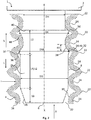
- Fig. 1
- eine Teilschnittansicht senkrecht zu einer Mittelachse auf eine erste Ausführung einer Verbindungsanordnung mit zwei Wellenelementen als Halteelemente,
- Fig. 2
- eine Teilschnittansicht senkrecht zu der Mittelachse auf eine zweite Ausführung einer Verbindungsanordnung mit einem Wellenelement und einem Haltezahn als Halteelemente und
- Fig. 3
- einen Längsschnitt durch ein sinusförmiges Wellrohr in einem nicht aufgesteckten Zustand.
- In den verschiedenen Figuren der Zeichnung sind gleiche Teile stets mit denselben Bezugszeichen versehen.
- Zu der anschließenden Beschreibung wird beansprucht, dass die Erfindung nicht auf die Ausführungsbeispiele und dabei nicht auf alle oder mehrere Merkmale von beschriebenen Merkmalskombinationen beschränkt ist, vielmehr ist jedes einzelne Teilmerkmal des/jedes Ausführungsbeispiels auch losgelöst von allen anderen im Zusammenhang damit beschriebenen Teilmerkmalen für sich und auch in Kombination mit beliebigen Merkmalen eines anderen Ausführungsbeispiels von Bedeutung für den Gegenstand der Erfindung.
- Die
Figuren 1 und2 zeigen eine Verbindungsanordnung 1. Wie dargestellt, weist die Verbindungsanordnung 1 ein einstückiges Verbinderteil 2 und ein fluidisch mit dem Verbinderteil 2 verbundenes Wellrohr 4 auf. - Bei dem Wellrohr 4 handelt es sich insbesondere um ein sinusförmiges Wellrohr 4 entsprechend den
Figuren 1 und2 , welches vorteilhaft flexibel, stauchbar und gegen radialwirkende Einflüsse widerstandsfähig ist. - Das Verbinderteil 2 weist einen, sich entlang einer Mittelachse X erstreckenden, nicht dargestellten, Durchgangskanal auf. Der Durchgangskanal mündet dabei einseitig zu dem Verbinderteil 2, wie in den
Figuren 1 und2 dargestellt, in einer Austrittsöffnung 6 eines an dem Verbinderteil 2 angeformten Dorns 8. Dabei weist der Dorn 8 vorzugsweise einen Mündungsbereich 10 auf, wobei der Außendurchmesser des Dorns 8 im Mündungsbereich 10 an der Austrittsöffnung 6 vorzugsweise geringer ist als der kleinste Innendurchmesser des Wellrohrs 4. - Weiterhin weist der Dorn 8 einen Haltebereich 12 und einen Dichtbereich 14 auf, wobei im Haltebereich 12 mindestens zwei Halteelemente axial zur Mittelachse X benachbart zueinander angeordnet sind. Der Dichtbereich 14 schließt sich dabei vorzugsweise unmittelbar an den Mündungsbereich 10 an.
- Das Wellrohr 4 ist mit einem gewellten Aufsteckabschnitt in eine Aufsteckrichtung A auf den Dorn 8 aufgesteckt. Zweckmäßig ist das Wellrohr 4 über die gesamte Länge gewellt ausgebildet. Das Wellrohr 4 weist eine Wellrohrwandung 16 auf, wobei ein Innenmantel 18 des Wellrohrs 4 einen Rohrleitungskanal 20 umschließt. Wie in den
Figuren 1 und2 beispielhaft dargestellt, weist die Wellrohrwandung 16 einen Verlauf auf, welcher stets von einem Wellenberg 22 in ein Wellental 24 übergeht, wobei in einem unbelasteten und unaufgesteckten Zustand, wie inFigur 3 dargestellt, ein Innendurchmesser DT des Wellrohrs 4 im Wellental 24 geringer ist als ein Innendurchmesser DB bei einem Wellenberg 22. - Das Wellrohr 4 ist in der Verbindungsanordnung 1 in dem Haltebereich 12 und dem Dichtbereich 14 des Dorns 8 angeordnet, wobei das Wellrohr 4, entsprechend den
Figuren 1 und2 , fluidisch mit dem Durchgangskanal des Verbinderteils 2 verbunden ist. Insbesondere wird das Wellrohr 4 über den Dichtbereich 14 auf den Dorn 8 derart aufgesteckt, dass er, wie beschrieben und in denFiguren 1 und2 dargestellt, sowohl im Dichtbereich 14 als auch im Haltebereich 12 angeordnet ist. - Erfindungsgemäß sind der Haltebereich 12 und der Dichtbereich 14, entsprechend den Ausführungen in den
Figuren 1 und2 , axial zu der Mittelachse X hintereinander angeordnet. Insbesondere schließt sich, wie in denFiguren 1 und2 dargestellt, dem Mündungsbereich 10 in Aufsteckrichtung A gesehen der Dichtbereich 14 und nachfolgend der Haltebereich 12 an. Die Trennung von dem Dichtbereich 14 und dem Haltebereich 12 hat zur Folge, dass das Wellrohr 4 im Dichtbereich 14 und Haltebereich 12 anders, insbesondere unabhängig vom jeweils anderen Bereich, radial gedehnt und axial gehalten werden kann. - Der Dorn 8 hat erfindungsgemäß im Dichtbereich 14 eine glatte, zum Wellrohr 4 weisende Oberfläche 26 ausgebildet, welche einen größeren, zum Wellrohr 4 weisenden Außendurchmesser DD aufweist als ein zum Dorn 8 weisender Innendurchmesser DT des Wellrohrs 4 im Wellental 24. Insbesondere ist die Oberfläche 26 des Dorns 8 im Dichtbereich 14 parallel zu der Mittelachse X verlaufend ausgebildet. Damit erfüllt der Dichtbereich 14 auf Grund einer radialen Dehnung des Wellrohrs 4 im Dichtbereich 14 den Zweck, dass sich das Wellrohr 4 mit zumindest einem Wellental 24 nicht von dem Dorn 8 abhebt und eine Leckage entsteht.
- Zwecks einer einfachen Montage wird das Wellrohr 4 in einer vorteilhaften Ausführung über den Mündungsbereich 10, welcher vorzugsweise eine konisch ausgebildete und sich im Durchmesser in Aufsteckrichtung A erweiternde, zum Wellrohr 4 weisende Oberfläche 28 aufweist, auf den Außendurchmesser DD des Dorns 8 im Dichtbereich 14 aufgedehnt.
- Erfindungsgemäß ist zumindest ein Halteelement als ein zu der Mittelachse X, insbesondere vollumfängliches, Wellenelement 30 des Dorns 8 ausgebildet, welches an einem Wellenmaximum 32 des Wellenelements 30 einen größeren, zum Wellrohr 4 weisenden Außendurchmesser DM aufweist als der Innendurchmesser DT des Wellrohrs 4 im Wellental 24. Der Dichtbereich 14 des Dorns 8 hat mittels des Wellenelements 30, bzw. der Halteelemente, die Wirkung, dass sich das Wellrohr 4 nicht gegen die Aufsteckrichtung A bis zum Erreichen einer bestimmten, gegen die Aufsteckrichtung A wirkenden Lösekraft L von dem Dorn 8 löst. Vorzugsweise ist das Wellrohr 4 beim Erreichen bzw. Überschreiten der Lösekraft L gegen die Aufsteckrichtung A zerstörungsfrei von dem Dorn 8 trennbar.
- Ein weiterer Vorteil besteht im Wellenelement 30 des Dorns 8 darin, dass durch die Wellenform das Wellrohr 4 mit seinem Aufsteckabschnitt leichter auf den Dorn 8 aufgesteckt werden kann, wobei sich das Wellenelement 30 des Dorns 8, wie in den
Figuren 1 und2 dargestellt, am Wellenmaximum 32 vorteilhaft zwischen zwei Wellentäler 24 legt und einen axialen Widerstand gegen eine Bewegung des Wellrohrs 4 axial zu der Mittelachse X erzeugt. -
Figur 1 zeigt dabei eine zweckmäßige Ausführung, gemäß welcher zumindest zwei, insbesondere wie dargestellt genau zwei Halteelemente als zwei zu der Mittelachse X, insbesondere vollumfängliche, Wellenelemente 30 des Dorns 8 ausgebildet sind. Dabei weisen die Wellenelemente 30 des Dorns jeweils an einem Wellenmaximum 32 des jeweiligen Wellenelementes 30 einen größeren, zum Wellrohr 4 weisenden Außendurchmesser DM auf als der Innendurchmesser DT des Wellrohrs 4 im Wellental 24. -
Figur 2 zeigt eine bevorzugte Ausführung, wobei das zumindest eine Wellenelement 30 des Dorns 8 mit einem andersartig ausgebildeten Halteelement kombiniert wird, wodurch die vorteilhaften Eigenschaften der unterschiedlichen Halteelemente kombiniert werden. - Auf Grund der axialen Trennung auf dem Dorn 8 zwischen dem Dichtbereich 14 und dem Haltebereich 12 in der erfindungsgemäßen Art und Weise wird durch ein synergetisches Zusammenwirken von Dichtbereich 14 und Haltebereich 12 eine Überlagerung zwischen radialen und axialen Spannungen verringert, wodurch das Wellrohr 4 für eine vorteilhafte Dichtungseigenschaft geringfügiger radial gedehnt bzw. für eine ausreichende axiale Haltekraft geringfügiger axial blockiert und/oder radial verspannt werden muss.
- Vorteilhaft wird mit der erfindungsgemäßen Ausführung eine Verbindungsanordnung 1 bereitgestellt, welche auf Grund eines Wellenelements 30 des Dorns 8 besonders vorteilhaft für sinusförmige Wellrohre 4 geeignet ist. Das Wellrohr 4 der Verbindungsanordnung 1 ist dabei radial elastisch dehnbar ausgebildet, wobei beim Anordnen des Wellrohrs 4 auf dem Dorn 8 das Wellrohr 4 vorzugsweise im elastischen Bereich gedehnt wird. Eine Dehnung im elastischen Bereich begünstigt die Mehrfachanwendung der Verbindungsanordnung 1 bzw. ermöglicht eine zerstörungsfreie Demontage. Gegen die radiale Dehnung des Wellrohrs 4 durch den Dorn 8 wirkt eine radiale Rückstellkraft F, welche insbesondere von der Geometrie und dem Werkstoff des Wellrohrs 4, aber auch von Umwelteinflüssen, wie z. B. der Umgebungstemperatur abhängt und das Wellrohr 4 dichtend auf dem Dorn 8 anordnet.
- In einer vorteilhaften Ausführung weist das Wellenelement 30 des Dorns 8 eine Halteschräge 34 auf, insbesondere entsprechend den
Figuren 1 und2 . Die Halteschräge 34 verringert den Außendurchmesser DM von dem Wellenmaximum 32 in Aufsteckrichtung A auf einen Haltedurchmesser DH. Über den Haltedurchmesser DH kann die radiale Verspannung des Wellrohrs 4 im Haltebereich 12 angepasst werden. Vorzugsweise ist der Haltedurchmesser DH derart gewählt, dass das Wellrohr 4 bei einer elastischen Rückverformung nach dem Wellenmaximum 32 auf dem Dorn 8 mit dem Haltedurchmesser DH zumindest mit einem Wellental 24 anliegt. - Zweckmäßig weist das Wellenelement 30 des Dorns 8 eine Einführschräge 36 auf, welche den Außendurchmesser des Dorns 8 in Aufsteckrichtung A auf den Außendurchmesser DM im Wellenmaximum 32 vergrößert. Mittels der Einführschrägen 36 kann der Außendurchmesser DM des Dorns 8 im Wellenmaximum 32 radial zur Mittelachse X größer ausgebildet sein, wobei die Einführschräge 36 dabei das Überwinden des Wellenmaximums 32 für das Wellrohr 4 erleichtert und damit eine aufzubringende Steckkraft S verringert.
- In einer alternativen, nicht dargestellten Ausführung ohne eine Einführschräge 36 entspricht der Außendurchmesser DM des Dorns 8 im Wellenmaximum 32 dem Außendurchmesser DD im Dichtbereich 14, so dass das Wellenelement 30 des Dorns 8 lediglich durch die Halteschräge 34 gebildet wird.
- Die Schrägen 34, 36 haben die vorteilhafte Eigenschaft, dass sie einen Kompromiss zwischen einem Montageaufwand und einem Demontageaufwand darstellen, indem die aufzubringenden Steck- und Lösekräfte S, L durch die jeweiligen Steigungen angepasst werden können. Weiterhin hat eine Ausführung, die sowohl eine Einführschräge 36 als auch eine Halteschräge 34 aufweist, den Vorteil, dass sich das Wellenelement 30 des Dorns 8 am Wellenmaximum 32 des Wellenelements 30 zwischen zwei Wellentälern 24 des Wellrohrs 4 anordnet und weiter in die radiale Richtung eines Wellenberges 22 ragt. Das Wellrohr 4 ist dadurch stärker gegen eine axiale Bewegung zur Mittelachse X blockiert bzw. behindert. Weiterhin ist die Anordnung des Wellenmaximums 32 des Wellenelements 30 im Bereich eines Wellenberges 22 von Vorteil, weil der Außendurchmesser DM des Dorns 8 im Wellenmaximum 32 größer gestaltet werden kann. Beim Aufstecken des Wellrohrs 4 überwinden die betreffenden Wellentäler 24 das Wellenmaximum 32 des Wellenelements 30 lediglich einmal, wobei sich entsprechend den
Figuren 1 und2 in einer aufgesteckten Lage das Wellenelement 30 des Dorns 8 mit seinem Wellenmaximum 32 des Wellenelements 30 benachbart zu einem Wellenberg 22 befindet. Das Wellrohr 4 bei dem Wellenberg 22 weist einen größeren Innendurchmesser DB auf als im Wellental 24. Dadurch wird das Wellrohr 4 über seine Standzeit weniger belastet bei einem trotzdem hohen Lösewiderstand, welcher durch den geringeren Innendurchmesser DT des Wellrohrs 4 im Wellental 24 gewährleistet wird. - Im Sinne einer vorteilhaften Einstellung der Steck- und Lösekräfte S, L ist in einer bevorzugten Variante die Einführschräge 36 in Aufsteckrichtung A vorzugsweise flacher zum Wellenmaximum 32 des Wellenelements 30 ansteigend ausgebildet als die Halteschräge 34 gegen die Aufsteckrichtung A zu dem Wellenmaximum 32 des Wellenelements 30. Diese Ausführung ist in den
Figuren 1 und2 dargestellt. Zweckmäßig ist dadurch die aufzuwendende Lösekraft L gegen die Aufsteckrichtung A zum Lösen des Wellrohrs 4 von dem Verbinderteil 2 größer als die aufzuwendende Steckkraft S in Aufsteckrichtung A zum Aufstecken des Wellrohrs 4. - Entsprechend der in den
Figuren 1 und2 dargestellten bevorzugten Ausführungsform ist zumindest die Halteschräge 34 in einem Anlagebereich für das Wellental 24 des Wellrohrs 4 bogenförmig mit einem Halteradius 38 gegen die Aufsteckrichtung A zum Wellenmaximum 32 des Wellenelements 30 ansteigend ausgebildet. Insbesondere sinusförmige Wellrohre 4 können sich dabei leicht zumindest im Anlagebereich an die in einem Halteradius 38 bogenförmige ausgebildete Halteschräge 34 anlegen und bei einer axialen Beanspruchung gegen die Aufsteckrichtung A sich zu einer großflächigen Anlage an der Halteschräge 34 verformen. Zweckmäßig ist das Wellrohr 4 durch ein derartiges Wellenelement 30 des Dorns 8 auf Grund der großen Auflagefläche zumindest teilweise, insbesondere größtenteils, durch eine Reibkraft auf dem Dorn 8 gegen die Aufsteckrichtung A gehalten. Insbesondere wird durch die radiale Rückstellkraft F auf Grund der Aufdehnung des Wellrohrs 4 bzw. des Wellentals 24 eine Anpresskraft erzeugt. Insbesondere verringert diese Ausführung weiterhin die Notwendigkeit von scharfkantigen Haltezähnen 40 bzw. macht scharfkantige Haltezähne 40 unnötig. - Die vorteilhafte Wirkung des Wellenelements 30 mit einer bogenförmigen Halteschräge 34 lässt sich auch in einer vorteilhaften Ausführung, wie in den
Figuren 1 und2 dargestellt, dadurch umsetzen, dass der Halteradius 38 der bogenförmigen Halteschräge 34 einem Wellenradius 42 eines Innenmantelabschnitts 44 des Wellrohrs 4 im Bereich des Wellentals 24 entspricht. Eine derartige vorteilhafte Ausführung hat den Vorteil, dass die Halteschräge 34 derart auf den Innenmantelabschnitt 44 des Wellrohrs 4 angepasst ausgebildet ist, dass ohne eine Anpressung des Wellentals 24 an die Halteschräge 34, das Wellrohr 4 großflächig an der Halteschräge 34 anliegen würde. Die Halteschräge 34 ist daher in einem nicht aufgesteckten Zustand des Wellrohres 4 entsprechendFigur 3 gekennzeichnet. Zweckmäßig wird eine Reibfläche und dadurch der axiale Widerstand bzw. die aufzubringende Lösekraft L gegen die Aufsteckrichtung A erhöht. - Zweckmäßig weist der Dorn 8 eine Außenmantelfläche 46 auf, welche zumindest im Bereich der Halteschräge 34 vorzugsweise eine Haltestruktur ausgebildet hat. Die Ausführung einer Halteschräge 34 mit einer Haltestruktur ist nicht dargestellt. Die Haltestruktur steigert die Reibkraft zumindest gegen die Aufsteckrichtung A zwischen dem Wellrohr 4 und dem Dorn 8 bzw. dem Wellenelement 30 des Dorns 8. Diese Ausführung verringert vorteilhaft die Gefahr eines Lösens des Wellrohrs 4 vom Dorn 8 gegen die Aufsteckrichtung A, indem die aufzubringenden Lösekräfte L erhöht werden. Haltestrukturen im Sinne dieser Erfindung können als eine aufgeraute Oberflächenstruktur, Beulen oder Rillen ausgebildet sein.
- In
Figur 2 ist eine besonders bevorzugte Ausführungsform der Erfindung dargestellt. Insbesondere um besonders großen Druckbelastungen in dem Rohrleitungskanal 20 oder einer hohen Belastung der Verbindungsanordnung 1, welche die Gefahr eines Lösens des Wellrohrs 4 vom Verbinderteil 2 auslösen könnte, vorzubeugen, ist vorzugsweise ein Halteelement als ein zu der Mittelachse X, insbesondere vollumfänglicher, Haltezahn 40 ausgebildet. - Insbesondere weist der Haltezahn 40, wie in
Figur 2 dargestellt, eine Aufsteckschräge 48 auf, welche vorzugsweise den Außendurchmesser des Dorns 8 in Aufsteckrichtung A auf einen Klemmdurchmesser DK vergrößert. Zweckmäßig weist der Haltezahn 40 dabei eine in Aufsteckrichtung A weisende Klemmkante, oder, wie inFigur 2 dargestellt, eine Schneidkante 50 auf. Der Haltezahn 40 ergänzt dabei das Wellenelement 30 und sorgt für eine gesteigerte Haltekraft und verhindert, dass sich das Wellrohr 4 gegen die Aufsteckrichtung A von dem Dorn 8 löst. Mittels der Klemmkante blockiert der Haltezahn 40 vorteilhaft das Wellental 24 gegen die Aufsteckrichtung A zumindest formschlüssig. Bei der Ausführung mit einer Schneidkante 50 gräbt sich die Schneidkante 50 in den Innenmantel 18 des Wellrohrs 4, so dass sich das Wellrohr 4 nicht gegen die Aufsteckrichtung A von dem Dorn 8 löst. - Insbesondere wirken der Haltezahn 40 und das Wellenelement 30 des Dorns 8 synergetisch derart zusammen, dass Beschädigungen in dem Innenmantel 18 des Wellrohrs 4 möglichst axialdistanziert zur Mittelachse X von dem Dichtbereich 14 auftreten. Erreicht wird dies mittels einer vorteilhaften, in
Figur 2 dargestellten, Ausführung, gemäß welcher das Wellenelement 30 des Dorns 8 axial zur Mittelachse X zwischen dem Haltezahn 40 und dem Dichtbereich 14 angeordnet ist. - Ein anderer synergetischer Effekt bewirkt, dass durch den Haltezahn 40 für einen ausreichenden Widerstand gegen ein Lösen gegen die Aufsteckrichtung A im Vergleich zu bekannten Verbindungsanordnungen mit ausschließlich einem oder mehreren Haltezähnen 40 weniger Material des Wellrohrs 4 abgetragen wird und insbesondere bei einer Ausführung mit nur einem Haltezahn 40 dieser sich nicht oder nur geringfügiger in die Wellrohrwandung 16 des Wellrohrs 4 eingräbt.
- Insbesondere entspricht der Klemmdurchmesser DK des Dorns 8 mindestens dem Außendurchmesser DM des Wellrohrs 4 im Wellenmaximum 32 des Wellenelements 30. Weiterhin ist es zweckmäßig, wenn in Aufsteckrichtung A unmittelbar hinter der Klemmkante oder der Schneidkante 50 der Außendurchmesser des Dorns 8 dem Haltedurchmesser DH entspricht.
- In einer abgewandelten Variante ist die Klemmkante oder die Schneidkante 50 als sprunghafter Wechsel, von dem Klemmdurchmesser DK auf einen kleineren Durchmesser des Dorns 8, insbesondere dem Haltedurchmesser DH ausgebildet.
- In einer vorteilhaften und in den
Figuren 1 und2 dargestellten Ausführungsform ist der Haltedurchmesser DH des Dorns 8 geringer als der Außendurchmesser DD des Dorns 8 im Dichtbereich 14. Dadurch wird das Wellrohr 4 im Haltebereich 12 geringfügiger radial belastet, was aufgrund des Halteelements 40 und des axial versetzten Dichtbereichs 14 dadurch möglich ist, dass die radiale Verspannung vornehmlich zum Wahren der notwendigen Dichtigkeit erforderlich ist. Somit summieren sich die Belastungen im Haltebereich 12 nicht auf ein kritisches Niveau, wodurch die Standzeit verbessert wird. - Ebenfalls in den
Figuren 1 und2 ist eine bevorzugte Ausführung dargestellt, wonach der Außendurchmesser DM des Wellenelements 30 des Dorns 8 im Wellenmaximum 32 des Wellenelements 30 größer ist als der Außendurchmesser DD des Dorns 8 im Dichtbereich 14. Dadurch wird es in beschriebener Art und Weise ermöglicht, dass sich das Wellenelement 30 des Dorns 8 zumindest teilweise im Bereich eines Wellenberges 22 des Wellrohrs 4 anordnet und den Widerstand gegen Bewegungen axial zur Mittelachse X erhöht. - Besonders bevorzugt ist eine Bemaßung, bei der der Außendurchmesser DM des Wellenelements 30 des Dorns 8 im Wellenmaximum 32 des Wellenelements 30 in einem Bereich von 10 % bis 35 %, insbesondere 15 % bis 30 %, vorzugsweise 20 % bis 25 % größer ist als der Innendurchmesser DT des Wellrohrs 4 im Wellental 24.
- Gemäß einer weiteren zweckmäßigen Ausführung ist der Außendurchmesser DD des Dorns 8 im Dichtbereich 14 in einem Bereich von 5 % bis 30 %, insbesondere 10 % bis 25 %, vorzugsweise 15 % bis 20 % größer als der Innendurchmesser DT des Wellrohrs 4 im Wellental 24.
- In einer weiteren Ausführung der Erfindung sind die Dichtungseigenschaften der Verbindungsanordnung 1 dadurch verbessert, dass der Dichtbereich 14 eine axiale Erstreckung 52 zur Mittelachse X aufweist, welche mindestens einem axial zum Rohrleitungskanal 20 gemessenen Abstand 54 zwischen zwei Wellentälern 24 des Wellrohrs 4 entspricht. Insbesondere wird von einem axialen Abstand in einem, in
Figur 3 dargestellten, nicht aufgesteckten Zustand und insbesondere nicht gestauchten Zustand des Wellrohrs 4 ausgegangen. In denFiguren 1 und2 ist eine besonders bevorzugte Ausführung abgebildet, gemäß welcher der Dichtbereich 14 eine axiale Erstreckung 52 zur Mittelachse X aufweist, welche mindestens eineinhalbmal einem zum Rohrleitungskanal 20 axialen Abstand 54 zwischen zwei Wellentälern 24 des Wellrohrs 4 entspricht. - Vorzugsweise beträgt der einfache Abstand 54 zwischen zwei Wellentälern 24 4 mm, daraus ergibt sich für die vorteilhafte Ausführung eine Erstreckung 52 des Dichtbereichs 14 von mindestens 4 mm, besonders bevorzugt 6 mm, axial zur Mittelachse X.
- Für eine besonders günstige und effiziente Herstellung der Verbindungsanordnung 1 hat sich vorteilhaft die Verwendung von sinusförmigen Wellrohren 4 herausgestellt. Im Besonderen kann das Verbinderteil 2 hinsichtlich der Herstellung verbessert werden, indem das Verbinderteil 2 monolithisch einstückig ausgebildet ist. Als vorteilhaft hat sich zudem herausgestellt, wenn das Verbinderteil 2 aus einem thermoplastischen Kunststoff ausgebildet ist.
- Die Erfindung ist nicht auf die dargestellten und beschriebenen Ausführungsbeispiele beschränkt, sondern umfasst auch alle im Sinne der Erfindung gleichwirkenden Ausführungen. Es wird ausdrücklich betont, dass die Ausführungsbeispiele nicht auf alle Merkmale in Kombination beschränkt sind, vielmehr kann jedes einzelne Teilmerkmal auch losgelöst von allen anderen Teilmerkmalen für sich eine erfinderische Bedeutung haben. Ferner ist die Erfindung bislang auch noch nicht auf die im Anspruch 1 definierte Merkmalskombination beschränkt, sondern kann auch durch jede beliebige andere Kombination von bestimmten Merkmalen aller insgesamt offenbarten Einzelmerkmale definiert sein. Dies bedeutet, dass grundsätzlich praktisch jedes Einzelmerkmal des Anspruchs 1 weggelassen beziehungsweise durch mindestens ein an anderer Stelle der Anmeldung offenbartes Einzelmerkmal ersetzt werden kann.
-
- 1
- Verbindungsanordnung
- 2
- Verbinderteil
- 4
- Wellrohr
- 6
- Austrittsöffnung
- 8
- Dorn
- 10
- Mündungsbereich
- 12
- Haltebereich
- 14
- Dichtbereich
- 16
- Wellrohrwandung
- 18
- Innenmantel
- 20
- Rohrleitungskanal
- 22
- Wellenberg
- 24
- Wellental
- 26
- Oberfläche im Dichtbereich
- 28
- Oberfläche im Mündungsbereich
- 30
- Wellenelement
- 32
- Wellenmaximum
- 34
- Halteschräge
- 36
- Einführschräge
- 38
- Halteradius
- 40
- Haltezahn
- 42
- Wellenradius
- 44
- Innenmantelabschnitt
- 46
- Außenmantelfläche
- 48
- Aufsteckschräge
- 50
- Schneidkante
- 52
- Axiale Erstreckung des Dichtbereichs
- 54
- Abstand zwischen zwei Wellentälern
- X
- Mittelachse
- L
- Lösekraft
- S
- Steckkraft
- A
- Aufsteckrichtung
- F
- Rückstellkraft
- DD
- Durchmesser des Dorns im Dichtbereich
- DK
- Klemmdurchmesser
- DB
- Innendurchmesser bei einem Wellenberg
- DT
- Innendurchmesser bei einem Wellental
- DH
- Haltedurchmesser
- DM
- Durchmesser des Wellenelements im Wellenmaximum
Claims (16)
- Verbindungsanordnung (1) aufweisend ein einstückiges Verbinderteil (2) und ein fluidisch mit dem Verbinderteil (2) verbundenes Wellrohr (4), wobei das Verbinderteil (2) einen sich entlang einer Mittelachse (X) erstreckenden Durchgangskanal aufweist, welcher einseitig zu dem Verbinderteil (2) in einem an dem Verbinderteil (2) angeformten Dorn (8) mündet, wobei der Dorn (8) einen Haltebereich (12) und einen Dichtbereich (14) aufweist, und im Haltebereich (12) mindestens zwei Halteelemente axial zur Mittelachse (X) benachbart zueinander angeordnet sind, wobei das Wellrohr (4) mit einem gewellten Aufsteckabschnitt in eine Aufsteckrichtung (A) auf den Dorn (8) aufgesteckt und in dem Haltebereich (12) und dem Dichtbereich (14) angeordnet und fluidisch mit dem Durchgangskanal des Verbinderteils (2) verbunden ist,
dadurch gekennzeichnet, dass
der Haltebereich (12) und der Dichtbereich (14) axial zu der Mittelachse (X) hintereinander angeordnet sind, wobei der Dorn (8) im Dichtbereich (14) eine glatte, zum Wellrohr (4) weisende Oberfläche (26) ausgebildet hat, welche einen größeren, zum Wellrohr (4) weisenden Außendurchmesser (DD) aufweist als ein zum Dorn (8) weisender Innendurchmesser (DT) des Wellrohrs (4) in einem Wellental (24), und zumindest ein Halteelement als ein zu der Mittelachse (X), insbesondere vollumfängliches, Wellenelement (30) des Dorns (8) ausgebildet ist, welches an einem Wellenmaximum (32) des Wellenelementes (30) einen größeren, zum Wellrohr (4) weisenden Außendurchmesser (DM) aufweist als der Innendurchmesser (DT) des Wellrohrs (4) in dem Wellental (24). - Verbindungsanordnung (1) nach Anspruch 1,
dadurch gekennzeichnet, dass
zumindest zwei, insbesondere genau zwei Halteelemente als zwei zu der Mittelachse (X), insbesondere vollumfängliche, Wellenelemente (30) des Dorns (8) ausgebildet sind, welche an einem Wellenmaximum (32) des jeweiligen Wellenelementes (30) einen größeren, zum Wellrohr (4) weisenden Außendurchmesser (DM) aufweisen als der Innendurchmesser (DT) des Wellrohrs (4) in dem Wellental (24). - Verbindungsanordnung (1) nach Anspruch 1 oder 2,
dadurch gekennzeichnet, dass das Wellenelement (30) eine Halteschräge (34) aufweist, welche den Außendurchmesser (DM) des Wellenelementes (30) im Wellenmaximum (32) in Aufsteckrichtung (A) auf einen Haltedurchmesser (DH) verringert und vorzugsweise eine Einführschräge (36) aufweist, welche den Außendurchmesser des Dorns (8) in Aufsteckrichtung (A) auf den Außendurchmesser (DM) im Wellenmaximum (32) vergrößert. - Verbindungsanordnung (1) nach Anspruch 3,
dadurch gekennzeichnet, dass die Einführschräge (36) in Aufsteckrichtung (A) flacher zum Wellenmaximum (32) ansteigend ausgebildet ist als die Halteschräge (34) gegen die Aufsteckrichtung (A) zu dem Wellenmaximum (32) des Wellenelements (30). - Verbindungsanordnung (1) nach einem der Ansprüche 2 bis 4,
dadurch gekennzeichnet, dass zumindest die Halteschräge (34) in einem Anlagebereich für das Wellental (24) des Wellrohrs (4) bogenförmig mit einem Halteradius (38) gegen die Aufsteckrichtung (A) zum Wellenmaximum (32) des Wellenelements (30) ansteigend ausgebildet ist. - Verbindungsanordnung (1) nach Anspruch 5,
dadurch gekennzeichnet, dass der Halteradius (38) der Halteschrägen (34) einem Wellenradius (42) eines Innenmantelabschnitts (44) des Wellrohrs (4) im Bereich des Wellentals (24) entspricht. - Verbindungsanordnung (1) nach einem der Ansprüche 2 bis 6,
dadurch gekennzeichnet, dass der Dorn (8) eine Außenmantelfläche (46) aufweist, welche zumindest im Bereich der Halteschräge (34) eine Haltestruktur ausgebildet hat, welche eine Reibkraft zumindest gegen die Aufsteckrichtung (A) zwischen dem Wellrohr (4) und dem Dorn (8) steigert. - Verbindungsanordnung (1) nach einem der Ansprüche 1 bis 7,
dadurch gekennzeichnet, dass ein Halteelement als ein zu der Mittelachse (X), insbesondere vollumfänglicher, Haltezahn (40) ausgebildet ist, welcher eine Aufsteckschräge (48) aufweist, welche den Außendurchmesser des Dorns (8) in Aufsteckrichtung (A) auf einen Klemmdurchmesser (DK) vergrößert und eine in Aufsteckrichtung (A) weisende Klemmkante oder Schneidkante (50) aufweist. - Verbindungsanordnung (1) nach Anspruch 8,
dadurch gekennzeichnet, dass der Klemmdurchmesser (DK) des Dorns (8) mindestens dem Außendurchmesser (DM) des Wellenelements (30) im Wellenmaximum (32) entspricht und vorzugsweise in Aufsteckrichtung (A) unmittelbar nach der Klemmkante oder Schneidkante (50) der Außendurchmesser des Dorns 8 dem Haltedurchmesser (DH) entspricht. - Verbindungsanordnung (1) nach einem der Ansprüche 3 bis 9,
dadurch gekennzeichnet, dass der Haltedurchmesser (DH) des Dorns (8) geringer ist als der Außendurchmesser (DD) des Dorns (8) im Dichtbereich (14). - Verbindungsanordnung (1) nach einem der Ansprüche 1 bis 10,
dadurch gekennzeichnet, dass der Außendurchmesser (DM) des Wellenelements (30) im Wellenmaximum (32) größer ist als der Außendurchmesser (DD) des Dorns (8) im Dichtbereich (14). - Verbindungsanordnung (1) nach einem der Ansprüche 1 bis 11,
dadurch gekennzeichnet, dass der Außendurchmesser (DM) des Wellenelements (30) im Wellenmaximum (32) in einem Bereich von 10 % bis 35 %, insbesondere 15 % bis 30 %, vorzugsweise 20 % bis 25 % größer ist als der Innendurchmesser (DT) des Wellrohrs (4) im Wellental (24). - Verbindungsanordnung (1) nach einem der Ansprüche 1 bis 12,
dadurch gekennzeichnet, dass der Außendurchmesser (DD) des Dorns (8) im Dichtbereich (14) in einem Bereich von 5 % bis 30 %, insbesondere 10 % bis 25 %, vorzugsweise 15 % bis 20 % größer ist als der Innendurchmesser (DT) des Wellrohrs (4) in dem Wellental (24). - Verbindungsanordnung (1) nach einem der Ansprüche 1 bis 13.
dadurch gekennzeichnet, dass der Dichtbereich (14) eine axiale Erstreckung (52) zur Mittelachse (X) aufweist, welche mindestens einem zu einem Rohrleitungskanal (20) axialen Abstand (54) zwischen zwei Wellentälern (24) des Wellrohrs (4) entspricht. - Verbindungsanordnung (1) nach Anspruch 14.
dadurch gekennzeichnet, dass der Dichtbereich (14) eine axiale Erstreckung (52) zur Mittelachse (X) aufweist, welche mindestens eineinhalbmal einem zum Rohrleitungskanal (20) axialen Abstand (54) zwischen zwei Wellentälern (24) des Wellrohrs (4) entspricht. - Verbindungsanordnung (1) nach einem der Ansprüche 1 bis 15,
dadurch gekennzeichnet, dass das Verbinderteil (2) monolithisch einstückig, insbesondere aus einem thermoplastischem Kunststoff, ausgebildet ist.
Applications Claiming Priority (1)
| Application Number | Priority Date | Filing Date | Title |
|---|---|---|---|
| DE102020108431.5A DE102020108431A1 (de) | 2020-03-26 | 2020-03-26 | Wellrohrverbindungsanordnung |
Publications (2)
| Publication Number | Publication Date |
|---|---|
| EP3885625A1 true EP3885625A1 (de) | 2021-09-29 |
| EP3885625B1 EP3885625B1 (de) | 2023-09-20 |
Family
ID=74871251
Family Applications (1)
| Application Number | Title | Priority Date | Filing Date |
|---|---|---|---|
| EP21162035.6A Active EP3885625B1 (de) | 2020-03-26 | 2021-03-11 | Wellrohrverbindungsanordnung |
Country Status (3)
| Country | Link |
|---|---|
| EP (1) | EP3885625B1 (de) |
| CN (1) | CN113446448B (de) |
| DE (1) | DE102020108431A1 (de) |
Citations (3)
| Publication number | Priority date | Publication date | Assignee | Title |
|---|---|---|---|---|
| FR2655126A1 (fr) * | 1989-11-30 | 1991-05-31 | Jaeger | Dispositif de raccordement etanche d'un tube annele sur une tubulure. |
| EP1681505A1 (de) * | 2005-01-12 | 2006-07-19 | Nobel Plastiques | Anschlussstutzen für Wellrohre und Rohr mit entsprechendem Stutzen |
| DE102015120508A1 (de) | 2015-11-26 | 2017-06-01 | Norma Germany Gmbh | Verbindungsanordnung für ein Kühlmittelsystem und Verfahren zur Herstellung einer Verbindungsanordnung |
Family Cites Families (14)
| Publication number | Priority date | Publication date | Assignee | Title |
|---|---|---|---|---|
| JPH06265073A (ja) * | 1993-03-15 | 1994-09-20 | Furukawa Electric Co Ltd:The | 波付管用継ぎ手 |
| JPH0684726U (ja) * | 1993-05-07 | 1994-12-02 | 住友電装株式会社 | プロテクタとコルゲートチューブとの固定構造 |
| DE29518712U1 (de) | 1995-11-25 | 1996-01-25 | BRUGG Rohrsysteme GmbH, 31515 Wunstorf | Anordnung zum Verbinden des Endes eines schraubenlinienförmig gewellten Metallrohres mit einem Anschlußstück |
| DE29618633U1 (de) * | 1996-10-25 | 1996-12-19 | Truplast Kunststofftechnik GmbH, 35428 Langgöns | Ablaufschlauchleitung |
| JP3225311B2 (ja) * | 1997-07-15 | 2001-11-05 | 東拓工業株式会社 | 環状凹凸波形管用ベルマウス |
| DE20104406U1 (de) | 2001-03-14 | 2001-08-16 | Fränkische Rohrwerke Gebr. Kirchner GmbH + Co. KG, 97486 Königsberg | Kraftfahrzeugsichtscheibenspritzwasserzuführanordnung |
| AT501505B1 (de) * | 2005-02-24 | 2007-06-15 | Vaillant Gmbh | Steckverbindung mit anschlussstutzen und leitung |
| JP2007071323A (ja) * | 2005-09-08 | 2007-03-22 | Sekisui Chem Co Ltd | コルゲート管の接続方法 |
| EP2650580B1 (de) * | 2012-04-12 | 2014-08-06 | Hydrogomma S.P.A. | Verbesserte Rohrhalterfassung mit einem Fischgrätenendstück zum Koppeln von Wellrohren |
| ES2399296B1 (es) * | 2013-01-22 | 2013-10-11 | Tucai, S.A. | Conjunto conector para conducciones de medios líquidos |
| CN203656442U (zh) * | 2013-12-10 | 2014-06-18 | 福建晟扬管道科技有限公司 | 一种带波纹塑管接头 |
| CN204114391U (zh) * | 2014-08-12 | 2015-01-21 | 无锡市锡山环宇金属软管有限公司 | 金属波纹管连接接头 |
| DE102017119201A1 (de) * | 2017-08-22 | 2019-02-28 | Norma Germany Gmbh | Steckverbinder und Rohrverbindung mit einem Steckverbinder |
| DE102018206052A1 (de) * | 2018-04-20 | 2019-10-24 | Audi Ag | Verbindungsstutzen zum Verbinden zweier Leitungsabschnitte |
-
2020
- 2020-03-26 DE DE102020108431.5A patent/DE102020108431A1/de not_active Withdrawn
-
2021
- 2021-03-11 EP EP21162035.6A patent/EP3885625B1/de active Active
- 2021-03-23 CN CN202110309582.1A patent/CN113446448B/zh active Active
Patent Citations (3)
| Publication number | Priority date | Publication date | Assignee | Title |
|---|---|---|---|---|
| FR2655126A1 (fr) * | 1989-11-30 | 1991-05-31 | Jaeger | Dispositif de raccordement etanche d'un tube annele sur une tubulure. |
| EP1681505A1 (de) * | 2005-01-12 | 2006-07-19 | Nobel Plastiques | Anschlussstutzen für Wellrohre und Rohr mit entsprechendem Stutzen |
| DE102015120508A1 (de) | 2015-11-26 | 2017-06-01 | Norma Germany Gmbh | Verbindungsanordnung für ein Kühlmittelsystem und Verfahren zur Herstellung einer Verbindungsanordnung |
Also Published As
| Publication number | Publication date |
|---|---|
| CN113446448B (zh) | 2023-11-28 |
| DE102020108431A1 (de) | 2021-09-30 |
| EP3885625B1 (de) | 2023-09-20 |
| CN113446448A (zh) | 2021-09-28 |
Similar Documents
| Publication | Publication Date | Title |
|---|---|---|
| EP1840437B1 (de) | Dichtungsanordnung für eine hydraulische Steckverbindung | |
| DE3424675C2 (de) | Schlauchkupplung | |
| EP3173675B1 (de) | Schlauchanschluss | |
| EP1781979B1 (de) | Steckverbindung für fluid-leitungen | |
| EP3266083B1 (de) | Dichtungstülle und kabeldurchführung mit einer dichtungstülle | |
| EP2724065B1 (de) | Schlauchnippel und korrespondierende schlauchanordnung | |
| CH667506A5 (de) | Drehbare schnappverbindung fuer rohrleitungen. | |
| DE102020108073A1 (de) | Steckverbinder mit Vormontagesicherung | |
| DE202020101638U1 (de) | Steckverbinder mit Vormontagesicherung | |
| EP3850260B1 (de) | Anschlussvorrichtung für rohrleitungen mit leckageanzeige | |
| EP0933579A2 (de) | Anschlussvorrichtung für Rohrleitungen | |
| EP3885625B1 (de) | Wellrohrverbindungsanordnung | |
| EP2281136B1 (de) | Steckverbindung für fluid-leitungen | |
| DE102021124681A1 (de) | Steckverbinder mit Vormontagesicherung | |
| DE202006005082U1 (de) | Zugfeste Steckverbindung für Rohrleitungen | |
| DE102017119201A1 (de) | Steckverbinder und Rohrverbindung mit einem Steckverbinder | |
| EP4077999B1 (de) | Steckverbinder und steckverbinderanordnung | |
| DE10340477B3 (de) | Zugfeste Rohrverbindung | |
| DE102022107490A1 (de) | Modularer Steckverbinder | |
| EP1239207B2 (de) | Federbandelement | |
| EP1945985B1 (de) | Verbindungssystem für leitungen, armaturen oder aggregate | |
| EP0180656B1 (de) | Rohrleitungskupplung für die Verbindung von Rohren aus spröden Werkstoffen | |
| DE102005038439A1 (de) | Steckverbindung für Fluid-Leitungen | |
| EP2442000A1 (de) | Verbindungsvorrichtung für zwei sich abschnittsweise überlappende Leitungen | |
| DE102020106671A1 (de) | Kupplungsstutzen |
Legal Events
| Date | Code | Title | Description |
|---|---|---|---|
| PUAI | Public reference made under article 153(3) epc to a published international application that has entered the european phase |
Free format text: ORIGINAL CODE: 0009012 |
|
| STAA | Information on the status of an ep patent application or granted ep patent |
Free format text: STATUS: THE APPLICATION HAS BEEN PUBLISHED |
|
| AK | Designated contracting states |
Kind code of ref document: A1 Designated state(s): AL AT BE BG CH CY CZ DE DK EE ES FI FR GB GR HR HU IE IS IT LI LT LU LV MC MK MT NL NO PL PT RO RS SE SI SK SM TR |
|
| STAA | Information on the status of an ep patent application or granted ep patent |
Free format text: STATUS: REQUEST FOR EXAMINATION WAS MADE |
|
| 17P | Request for examination filed |
Effective date: 20220309 |
|
| RBV | Designated contracting states (corrected) |
Designated state(s): AL AT BE BG CH CY CZ DE DK EE ES FI FR GB GR HR HU IE IS IT LI LT LU LV MC MK MT NL NO PL PT RO RS SE SI SK SM TR |
|
| GRAP | Despatch of communication of intention to grant a patent |
Free format text: ORIGINAL CODE: EPIDOSNIGR1 |
|
| STAA | Information on the status of an ep patent application or granted ep patent |
Free format text: STATUS: GRANT OF PATENT IS INTENDED |
|
| INTG | Intention to grant announced |
Effective date: 20230525 |
|
| GRAS | Grant fee paid |
Free format text: ORIGINAL CODE: EPIDOSNIGR3 |
|
| GRAA | (expected) grant |
Free format text: ORIGINAL CODE: 0009210 |
|
| STAA | Information on the status of an ep patent application or granted ep patent |
Free format text: STATUS: THE PATENT HAS BEEN GRANTED |
|
| AK | Designated contracting states |
Kind code of ref document: B1 Designated state(s): AL AT BE BG CH CY CZ DE DK EE ES FI FR GB GR HR HU IE IS IT LI LT LU LV MC MK MT NL NO PL PT RO RS SE SI SK SM TR |
|
| REG | Reference to a national code |
Ref country code: GB Ref legal event code: FG4D Free format text: NOT ENGLISH |
|
| REG | Reference to a national code |
Ref country code: CH Ref legal event code: EP |
|
| REG | Reference to a national code |
Ref country code: IE Ref legal event code: FG4D Free format text: LANGUAGE OF EP DOCUMENT: GERMAN |
|
| REG | Reference to a national code |
Ref country code: DE Ref legal event code: R096 Ref document number: 502021001493 Country of ref document: DE |
|
| P01 | Opt-out of the competence of the unified patent court (upc) registered |
Effective date: 20230918 |
|
| REG | Reference to a national code |
Ref country code: LT Ref legal event code: MG9D |
|
| PG25 | Lapsed in a contracting state [announced via postgrant information from national office to epo] |
Ref country code: GR Free format text: LAPSE BECAUSE OF FAILURE TO SUBMIT A TRANSLATION OF THE DESCRIPTION OR TO PAY THE FEE WITHIN THE PRESCRIBED TIME-LIMIT Effective date: 20231221 |
|
| REG | Reference to a national code |
Ref country code: NL Ref legal event code: MP Effective date: 20230920 |
|
| PG25 | Lapsed in a contracting state [announced via postgrant information from national office to epo] |
Ref country code: SE Free format text: LAPSE BECAUSE OF FAILURE TO SUBMIT A TRANSLATION OF THE DESCRIPTION OR TO PAY THE FEE WITHIN THE PRESCRIBED TIME-LIMIT Effective date: 20230920 Ref country code: RS Free format text: LAPSE BECAUSE OF FAILURE TO SUBMIT A TRANSLATION OF THE DESCRIPTION OR TO PAY THE FEE WITHIN THE PRESCRIBED TIME-LIMIT Effective date: 20230920 Ref country code: NO Free format text: LAPSE BECAUSE OF FAILURE TO SUBMIT A TRANSLATION OF THE DESCRIPTION OR TO PAY THE FEE WITHIN THE PRESCRIBED TIME-LIMIT Effective date: 20231220 Ref country code: LV Free format text: LAPSE BECAUSE OF FAILURE TO SUBMIT A TRANSLATION OF THE DESCRIPTION OR TO PAY THE FEE WITHIN THE PRESCRIBED TIME-LIMIT Effective date: 20230920 Ref country code: LT Free format text: LAPSE BECAUSE OF FAILURE TO SUBMIT A TRANSLATION OF THE DESCRIPTION OR TO PAY THE FEE WITHIN THE PRESCRIBED TIME-LIMIT Effective date: 20230920 Ref country code: HR Free format text: LAPSE BECAUSE OF FAILURE TO SUBMIT A TRANSLATION OF THE DESCRIPTION OR TO PAY THE FEE WITHIN THE PRESCRIBED TIME-LIMIT Effective date: 20230920 Ref country code: GR Free format text: LAPSE BECAUSE OF FAILURE TO SUBMIT A TRANSLATION OF THE DESCRIPTION OR TO PAY THE FEE WITHIN THE PRESCRIBED TIME-LIMIT Effective date: 20231221 Ref country code: FI Free format text: LAPSE BECAUSE OF FAILURE TO SUBMIT A TRANSLATION OF THE DESCRIPTION OR TO PAY THE FEE WITHIN THE PRESCRIBED TIME-LIMIT Effective date: 20230920 |
|
| PG25 | Lapsed in a contracting state [announced via postgrant information from national office to epo] |
Ref country code: NL Free format text: LAPSE BECAUSE OF FAILURE TO SUBMIT A TRANSLATION OF THE DESCRIPTION OR TO PAY THE FEE WITHIN THE PRESCRIBED TIME-LIMIT Effective date: 20230920 |
|
| PG25 | Lapsed in a contracting state [announced via postgrant information from national office to epo] |
Ref country code: IS Free format text: LAPSE BECAUSE OF FAILURE TO SUBMIT A TRANSLATION OF THE DESCRIPTION OR TO PAY THE FEE WITHIN THE PRESCRIBED TIME-LIMIT Effective date: 20240120 |
|
| PG25 | Lapsed in a contracting state [announced via postgrant information from national office to epo] |
Ref country code: ES Free format text: LAPSE BECAUSE OF FAILURE TO SUBMIT A TRANSLATION OF THE DESCRIPTION OR TO PAY THE FEE WITHIN THE PRESCRIBED TIME-LIMIT Effective date: 20230920 |
|
| PG25 | Lapsed in a contracting state [announced via postgrant information from national office to epo] |
Ref country code: SM Free format text: LAPSE BECAUSE OF FAILURE TO SUBMIT A TRANSLATION OF THE DESCRIPTION OR TO PAY THE FEE WITHIN THE PRESCRIBED TIME-LIMIT Effective date: 20230920 Ref country code: RO Free format text: LAPSE BECAUSE OF FAILURE TO SUBMIT A TRANSLATION OF THE DESCRIPTION OR TO PAY THE FEE WITHIN THE PRESCRIBED TIME-LIMIT Effective date: 20230920 Ref country code: IS Free format text: LAPSE BECAUSE OF FAILURE TO SUBMIT A TRANSLATION OF THE DESCRIPTION OR TO PAY THE FEE WITHIN THE PRESCRIBED TIME-LIMIT Effective date: 20240120 Ref country code: ES Free format text: LAPSE BECAUSE OF FAILURE TO SUBMIT A TRANSLATION OF THE DESCRIPTION OR TO PAY THE FEE WITHIN THE PRESCRIBED TIME-LIMIT Effective date: 20230920 Ref country code: EE Free format text: LAPSE BECAUSE OF FAILURE TO SUBMIT A TRANSLATION OF THE DESCRIPTION OR TO PAY THE FEE WITHIN THE PRESCRIBED TIME-LIMIT Effective date: 20230920 Ref country code: CZ Free format text: LAPSE BECAUSE OF FAILURE TO SUBMIT A TRANSLATION OF THE DESCRIPTION OR TO PAY THE FEE WITHIN THE PRESCRIBED TIME-LIMIT Effective date: 20230920 Ref country code: SK Free format text: LAPSE BECAUSE OF FAILURE TO SUBMIT A TRANSLATION OF THE DESCRIPTION OR TO PAY THE FEE WITHIN THE PRESCRIBED TIME-LIMIT Effective date: 20230920 Ref country code: PT Free format text: LAPSE BECAUSE OF FAILURE TO SUBMIT A TRANSLATION OF THE DESCRIPTION OR TO PAY THE FEE WITHIN THE PRESCRIBED TIME-LIMIT Effective date: 20240122 |
|
| PG25 | Lapsed in a contracting state [announced via postgrant information from national office to epo] |
Ref country code: PL Free format text: LAPSE BECAUSE OF FAILURE TO SUBMIT A TRANSLATION OF THE DESCRIPTION OR TO PAY THE FEE WITHIN THE PRESCRIBED TIME-LIMIT Effective date: 20230920 Ref country code: IT Free format text: LAPSE BECAUSE OF FAILURE TO SUBMIT A TRANSLATION OF THE DESCRIPTION OR TO PAY THE FEE WITHIN THE PRESCRIBED TIME-LIMIT Effective date: 20230920 |
|
| REG | Reference to a national code |
Ref country code: DE Ref legal event code: R097 Ref document number: 502021001493 Country of ref document: DE |
|
| PG25 | Lapsed in a contracting state [announced via postgrant information from national office to epo] |
Ref country code: DK Free format text: LAPSE BECAUSE OF FAILURE TO SUBMIT A TRANSLATION OF THE DESCRIPTION OR TO PAY THE FEE WITHIN THE PRESCRIBED TIME-LIMIT Effective date: 20230920 |
|
| PLBE | No opposition filed within time limit |
Free format text: ORIGINAL CODE: 0009261 |
|
| STAA | Information on the status of an ep patent application or granted ep patent |
Free format text: STATUS: NO OPPOSITION FILED WITHIN TIME LIMIT |
|
| PG25 | Lapsed in a contracting state [announced via postgrant information from national office to epo] |
Ref country code: DK Free format text: LAPSE BECAUSE OF FAILURE TO SUBMIT A TRANSLATION OF THE DESCRIPTION OR TO PAY THE FEE WITHIN THE PRESCRIBED TIME-LIMIT Effective date: 20230920 |
|
| 26N | No opposition filed |
Effective date: 20240621 |
|
| PG25 | Lapsed in a contracting state [announced via postgrant information from national office to epo] |
Ref country code: SI Free format text: LAPSE BECAUSE OF FAILURE TO SUBMIT A TRANSLATION OF THE DESCRIPTION OR TO PAY THE FEE WITHIN THE PRESCRIBED TIME-LIMIT Effective date: 20230920 |
|
| PG25 | Lapsed in a contracting state [announced via postgrant information from national office to epo] |
Ref country code: SI Free format text: LAPSE BECAUSE OF FAILURE TO SUBMIT A TRANSLATION OF THE DESCRIPTION OR TO PAY THE FEE WITHIN THE PRESCRIBED TIME-LIMIT Effective date: 20230920 |
|
| REG | Reference to a national code |
Ref country code: CH Ref legal event code: PL |
|
| PG25 | Lapsed in a contracting state [announced via postgrant information from national office to epo] |
Ref country code: BG Free format text: LAPSE BECAUSE OF FAILURE TO SUBMIT A TRANSLATION OF THE DESCRIPTION OR TO PAY THE FEE WITHIN THE PRESCRIBED TIME-LIMIT Effective date: 20230920 |
|
| PG25 | Lapsed in a contracting state [announced via postgrant information from national office to epo] |
Ref country code: LU Free format text: LAPSE BECAUSE OF NON-PAYMENT OF DUE FEES Effective date: 20240311 |
|
| PG25 | Lapsed in a contracting state [announced via postgrant information from national office to epo] |
Ref country code: MC Free format text: LAPSE BECAUSE OF FAILURE TO SUBMIT A TRANSLATION OF THE DESCRIPTION OR TO PAY THE FEE WITHIN THE PRESCRIBED TIME-LIMIT Effective date: 20230920 |
|
| PG25 | Lapsed in a contracting state [announced via postgrant information from national office to epo] |
Ref country code: MC Free format text: LAPSE BECAUSE OF FAILURE TO SUBMIT A TRANSLATION OF THE DESCRIPTION OR TO PAY THE FEE WITHIN THE PRESCRIBED TIME-LIMIT Effective date: 20230920 Ref country code: LU Free format text: LAPSE BECAUSE OF NON-PAYMENT OF DUE FEES Effective date: 20240311 Ref country code: BG Free format text: LAPSE BECAUSE OF FAILURE TO SUBMIT A TRANSLATION OF THE DESCRIPTION OR TO PAY THE FEE WITHIN THE PRESCRIBED TIME-LIMIT Effective date: 20230920 |
|
| REG | Reference to a national code |
Ref country code: BE Ref legal event code: MM Effective date: 20240331 |
|
| PG25 | Lapsed in a contracting state [announced via postgrant information from national office to epo] |
Ref country code: BE Free format text: LAPSE BECAUSE OF NON-PAYMENT OF DUE FEES Effective date: 20240331 |
|
| PG25 | Lapsed in a contracting state [announced via postgrant information from national office to epo] |
Ref country code: IE Free format text: LAPSE BECAUSE OF NON-PAYMENT OF DUE FEES Effective date: 20240311 |
|
| PG25 | Lapsed in a contracting state [announced via postgrant information from national office to epo] |
Ref country code: IE Free format text: LAPSE BECAUSE OF NON-PAYMENT OF DUE FEES Effective date: 20240311 Ref country code: BE Free format text: LAPSE BECAUSE OF NON-PAYMENT OF DUE FEES Effective date: 20240331 Ref country code: CH Free format text: LAPSE BECAUSE OF NON-PAYMENT OF DUE FEES Effective date: 20240331 |
|
| PGFP | Annual fee paid to national office [announced via postgrant information from national office to epo] |
Ref country code: AT Payment date: 20250417 Year of fee payment: 5 |
|
| PGFP | Annual fee paid to national office [announced via postgrant information from national office to epo] |
Ref country code: DE Payment date: 20250526 Year of fee payment: 5 |
|
| PG25 | Lapsed in a contracting state [announced via postgrant information from national office to epo] |
Ref country code: CY Free format text: LAPSE BECAUSE OF FAILURE TO SUBMIT A TRANSLATION OF THE DESCRIPTION OR TO PAY THE FEE WITHIN THE PRESCRIBED TIME-LIMIT; INVALID AB INITIO Effective date: 20210311 |
|
| PG25 | Lapsed in a contracting state [announced via postgrant information from national office to epo] |
Ref country code: HU Free format text: LAPSE BECAUSE OF FAILURE TO SUBMIT A TRANSLATION OF THE DESCRIPTION OR TO PAY THE FEE WITHIN THE PRESCRIBED TIME-LIMIT; INVALID AB INITIO Effective date: 20210311 |
|
| GBPC | Gb: european patent ceased through non-payment of renewal fee |
Effective date: 20250311 |
|
| PG25 | Lapsed in a contracting state [announced via postgrant information from national office to epo] |
Ref country code: TR Free format text: LAPSE BECAUSE OF FAILURE TO SUBMIT A TRANSLATION OF THE DESCRIPTION OR TO PAY THE FEE WITHIN THE PRESCRIBED TIME-LIMIT Effective date: 20230920 |
|
| PG25 | Lapsed in a contracting state [announced via postgrant information from national office to epo] |
Ref country code: GB Free format text: LAPSE BECAUSE OF NON-PAYMENT OF DUE FEES Effective date: 20250311 |
|
| PGFP | Annual fee paid to national office [announced via postgrant information from national office to epo] |
Ref country code: FR Payment date: 20260311 Year of fee payment: 6 |