EP3885609B1 - Riemenspannvorrichtung - Google Patents
Riemenspannvorrichtung Download PDFInfo
- Publication number
- EP3885609B1 EP3885609B1 EP21168114.3A EP21168114A EP3885609B1 EP 3885609 B1 EP3885609 B1 EP 3885609B1 EP 21168114 A EP21168114 A EP 21168114A EP 3885609 B1 EP3885609 B1 EP 3885609B1
- Authority
- EP
- European Patent Office
- Prior art keywords
- base member
- tensioning
- belt
- arm
- tensioning arm
- Prior art date
- Legal status (The legal status is an assumption and is not a legal conclusion. Google has not performed a legal analysis and makes no representation as to the accuracy of the status listed.)
- Active
Links
Images


Classifications
-
- F—MECHANICAL ENGINEERING; LIGHTING; HEATING; WEAPONS; BLASTING
- F16—ENGINEERING ELEMENTS AND UNITS; GENERAL MEASURES FOR PRODUCING AND MAINTAINING EFFECTIVE FUNCTIONING OF MACHINES OR INSTALLATIONS; THERMAL INSULATION IN GENERAL
- F16H—GEARING
- F16H7/00—Gearings for conveying rotary motion by endless flexible members
- F16H7/08—Means for varying tension of belts, ropes or chains
- F16H7/10—Means for varying tension of belts, ropes or chains by adjusting the axis of a pulley
- F16H7/12—Means for varying tension of belts, ropes or chains by adjusting the axis of a pulley of an idle pulley
- F16H7/1254—Means for varying tension of belts, ropes or chains by adjusting the axis of a pulley of an idle pulley without vibration damping means
- F16H7/1281—Means for varying tension of belts, ropes or chains by adjusting the axis of a pulley of an idle pulley without vibration damping means where the axis of the pulley moves along a substantially circular path
-
- F—MECHANICAL ENGINEERING; LIGHTING; HEATING; WEAPONS; BLASTING
- F16—ENGINEERING ELEMENTS AND UNITS; GENERAL MEASURES FOR PRODUCING AND MAINTAINING EFFECTIVE FUNCTIONING OF MACHINES OR INSTALLATIONS; THERMAL INSULATION IN GENERAL
- F16C—SHAFTS; FLEXIBLE SHAFTS; ELEMENTS OR CRANKSHAFT MECHANISMS; ROTARY BODIES OTHER THAN GEARING ELEMENTS; BEARINGS
- F16C33/00—Parts of bearings; Special methods for making bearings or parts thereof
- F16C33/30—Parts of ball or roller bearings
- F16C33/38—Ball cages
- F16C33/44—Selection of substances
-
- F—MECHANICAL ENGINEERING; LIGHTING; HEATING; WEAPONS; BLASTING
- F16—ENGINEERING ELEMENTS AND UNITS; GENERAL MEASURES FOR PRODUCING AND MAINTAINING EFFECTIVE FUNCTIONING OF MACHINES OR INSTALLATIONS; THERMAL INSULATION IN GENERAL
- F16H—GEARING
- F16H7/00—Gearings for conveying rotary motion by endless flexible members
- F16H7/08—Means for varying tension of belts, ropes or chains
- F16H7/10—Means for varying tension of belts, ropes or chains by adjusting the axis of a pulley
- F16H7/12—Means for varying tension of belts, ropes or chains by adjusting the axis of a pulley of an idle pulley
- F16H7/1209—Means for varying tension of belts, ropes or chains by adjusting the axis of a pulley of an idle pulley with vibration damping means
- F16H7/1218—Means for varying tension of belts, ropes or chains by adjusting the axis of a pulley of an idle pulley with vibration damping means of the dry friction type
-
- F—MECHANICAL ENGINEERING; LIGHTING; HEATING; WEAPONS; BLASTING
- F16—ENGINEERING ELEMENTS AND UNITS; GENERAL MEASURES FOR PRODUCING AND MAINTAINING EFFECTIVE FUNCTIONING OF MACHINES OR INSTALLATIONS; THERMAL INSULATION IN GENERAL
- F16H—GEARING
- F16H7/00—Gearings for conveying rotary motion by endless flexible members
- F16H7/08—Means for varying tension of belts, ropes or chains
- F16H2007/0802—Actuators for final output members
- F16H2007/081—Torsion springs
-
- F—MECHANICAL ENGINEERING; LIGHTING; HEATING; WEAPONS; BLASTING
- F16—ENGINEERING ELEMENTS AND UNITS; GENERAL MEASURES FOR PRODUCING AND MAINTAINING EFFECTIVE FUNCTIONING OF MACHINES OR INSTALLATIONS; THERMAL INSULATION IN GENERAL
- F16H—GEARING
- F16H7/00—Gearings for conveying rotary motion by endless flexible members
- F16H7/08—Means for varying tension of belts, ropes or chains
- F16H2007/0842—Mounting or support of tensioner
-
- F—MECHANICAL ENGINEERING; LIGHTING; HEATING; WEAPONS; BLASTING
- F16—ENGINEERING ELEMENTS AND UNITS; GENERAL MEASURES FOR PRODUCING AND MAINTAINING EFFECTIVE FUNCTIONING OF MACHINES OR INSTALLATIONS; THERMAL INSULATION IN GENERAL
- F16H—GEARING
- F16H7/00—Gearings for conveying rotary motion by endless flexible members
- F16H7/08—Means for varying tension of belts, ropes or chains
- F16H2007/0863—Finally actuated members, e.g. constructional details thereof
- F16H2007/0865—Pulleys
-
- F—MECHANICAL ENGINEERING; LIGHTING; HEATING; WEAPONS; BLASTING
- F16—ENGINEERING ELEMENTS AND UNITS; GENERAL MEASURES FOR PRODUCING AND MAINTAINING EFFECTIVE FUNCTIONING OF MACHINES OR INSTALLATIONS; THERMAL INSULATION IN GENERAL
- F16H—GEARING
- F16H7/00—Gearings for conveying rotary motion by endless flexible members
- F16H7/08—Means for varying tension of belts, ropes or chains
- F16H2007/0889—Path of movement of the finally actuated member
- F16H2007/0893—Circular path
Definitions
- a belt drive usually comprises an endless belt and at least two pulleys, one of which can act as the drive and one as the output of the belt drive.
- Such belt drives are used in particular on internal combustion engines of a motor vehicle to drive auxiliary units, with a first pulley sitting on the crankshaft of the internal combustion engine and driving the belt. Additional pulleys are assigned to the auxiliary units, such as the water pump, alternator or air conditioning compressor, and are driven in rotation by the belt drive.
- the auxiliary units are designed as consumers, i.e. they are driven by the pulley of the crankshaft via the belt.
- a belt tensioning device for a belt drive of the type mentioned is known.
- the belt tensioning device has a base body on which a tensioning arm is pivotably mounted.
- the belt tensioning device is designed in such a way that the pivot axis of the tensioning arm is arranged within the outer diameter of the belt pulley of the unit when installed.
- a belt tensioner with a housing and an arm with a bayonet-like connection is known.
- the housing has a locking flange and the arm has a locking tab, which work together.
- a bearing arrangement with two bearings is provided, with which the housing is rotatably mounted relative to the bolt.
- a belt tensioning device for a belt drive which has a base body, a tensioning arm that can be pivoted relative to it, and a spring that resiliently supports the tensioning arm in the circumferential direction.
- the base body and the tensioning arm are at least partially made of plastic, so that the belt tensioner has a low weight overall.
- Connecting means are provided for connecting the tensioning arm to the base body by means of an insertion and rotation movement.
- a tensioning device for drive belts which comprises a support body, a pivoting body mounted thereon and a tensioning roller arranged eccentrically thereon.
- a spring module is provided, which essentially consists of two pot-shaped housing parts made of sheet metal, which have a tension spring enclose. On the edge of the inner housing part, three retaining projections are formed, distributed around the circumference, which are snapped into place via an edge flange on the outer housing part. The snap connections are made by axially pressing the housing parts together via the edge-side retaining projections.
- the spring modules can be stored in this form.
- a traction device tensioning device with a guide device for guiding a traction device and with a tensioner for deflecting and damping a movement of the guide device.
- the tensioner has a housing with a cooling body.
- the cooling body is arranged on an outer peripheral surface of the housing and has several cooling fins.
- the cooling fins are designed as elongated webs with a rounded surface, which have a chamfer in their longitudinal extension.
- the present invention is based on the object of proposing a belt tensioning device for a belt drive which is simple and cost-effective to manufacture and enables good heat dissipation, so that it can withstand the technical requirements for use in a belt drive with a starter generator over a long service life.
- a solution according to the invention consists in a belt tensioning device for a belt drive, comprising the features of claim 1.
- a belt tensioning device for a belt drive not according to the invention can comprise a base body which can be firmly connected to a stationary component; at least one tensioning arm which is mounted so as to be pivotable about a pivot axis relative to the base body; a tensioning roller for tensioning the belt which is mounted on the tensioning arm so as to be rotatable about an axis of rotation; spring means with which the tensioning arm is resiliently supported in the circumferential direction; and a connecting arrangement for connecting the tensioning arm to the base body; wherein the tensioning arm has an opening for a drive part of an assembly which extends into the opening in the assembled state, wherein a wall of the tensioning arm surrounding the opening is provided with circumferentially distributed ribs, wherein the ribs have a greater thickness in a foot section than in a head section.
- the advantage of both belt tensioning devices is that they allow good heat dissipation and are easy to manufacture.
- the design of the connection arrangement in such a way that the tensioning arm and the base body can be connected to one another with a plug-in and rotating movement results in simple and cost-effective assembly.
- the larger contact surface area and the design of the ribs with variable width over height enable good heat dissipation from the contact points, so that it can withstand the technical requirements for use in a belt drive with a starter generator over a long service life.
- the belt tensioning device can be designed as a single-arm tensioner, i.e. it can have exactly one tensioning arm.
- the tensioning arm is spring-supported on the base body in the circumferential direction via the spring means.
- the belt tensioning device can also be designed as a two-arm tensioner, i.e. it can have exactly two tensioning arms. In this case, the two tensioning arms are supported against each other in the circumferential direction via the spring means.
- Two-arm tensioners are used in belt drives in which a starter generator is integrated into the belt drive as a further auxiliary unit, i.e.
- connection arrangement comprises several connection sections assigned to the base body and several connection sections assigned to the tensioning arm, which interact with one another.
- the base body connection sections and the tensioning arm connection sections are designed in such a way that the tensioning arm and the base body can be connected to one another by an insertion and rotation movement.
- the connection mentioned functions in the manner of a bayonet lock, so that the belt tensioning device can be easily installed.
- a contact surface area is formed between a base body connection section and an associated tensioning arm connection section.
- the contact surface area means the area of mutual axial support or mutual surface overlap between a base body connection section and an associated tensioning arm connection section.
- the first contact surface area between a first connecting section of the base body and a first connecting section of the clamping arm is larger than the second contact surface area between a second connecting section of the base body and a second connecting section of the clamping arm.
- the area of mutual overlap between the first connecting sections of the base body and the clamping arm is larger than the overlap area between the second connecting sections.
- the first contact surface area is at least 10% larger than the second contact surface area, in particular at least 20%, possibly also at least 30% larger than the second contact surface area.
- connection arrangement can also have three or more connection sections between the base body and the clamping arm, so that a correspondingly larger number of contact surface areas is formed. These additional areas can correspond in size to the first contact surface areas or the second contact surface areas or have a different size therefrom.
- connection arrangement is preferably designed in such a way that the clamping arm can only be inserted into the base body in exactly one predetermined rotational position. In this way, assembly is simplified and assembly time is shortened.
- error-preventing principles are also known as Poka Yoke.
- connection sections are distributed irregularly over the circumference and/or have different circumferential extensions.
- a recess is formed between two adjacent base body connecting sections in the circumferential direction.
- the clamping arm connecting sections are designed in the form of radial projections corresponding to the recesses.
- the clamping arm can thus be axially inserted into the base body in a rotational position in which the radial projections of the clamping arm are arranged in the circumferential areas of the recesses of the base body.
- the base body and/or the at least one tensioning arm has an opening into which a drive part of an assembly extends in the assembled state.
- the opening is designed so that the drive part can extend into the opening in the assembled state.
- the drive part can be, for example, a drive shaft and/or a pulley of the assembly.
- the wall of the tensioning arm surrounding the opening can be provided with ribs over at least part of its circumference.
- the ribs fulfill two functions in particular, namely, firstly, they dissipate frictional heat generated during operation from the belt tensioning device, whereby it is particularly advantageous for good heat dissipation if the ribs have a variable thickness over the height.
- the ribs support a targeted supply of air in the direction of the assembly to which the belt tensioning device is attached in order to cool it effectively.
- the ribs can be straight, angled or curved in relation to a longitudinal axis of the opening.
- the term angular ribs includes all shapes in which the flanks of the ribs or parts of them do not run parallel to the longitudinal axis.
- the ribs can also be designed in a helical or shovel-like manner.
- the ribs in the foot section have a variable thickness over the height, wherein the height of the foot section with variable thickness is at least 10%, in particular at least 20% of the total height of the rib. Due to the relatively long section with variable thickness, which decreases radially inward towards the free end of the rib, the heat of the tensioning arm can be very well introduced from the wall area into the ribs and from there released into the environment. Overall, the thermal load on the belt tensioner is thus reduced and the service life is increased accordingly.
- the ribs can have a constant thickness over the height in the head section, wherein the height of the head section with constant thickness can, for example, be at least 50% of the total height of the rib.
- the ribs can extend in the axial direction relative to the pivot axis or at least have a gradient component in the axial direction. Furthermore, it can be provided that - viewed in cross section - a The smallest distance formed between circumferentially adjacent ribs in the head section is greater than the smallest distance formed between two adjacent ribs in the foot section.
- a plurality of ribs are provided over the circumference, the wall of the clamping arm being provided with ribs over a circumferential section of at least 60°, in particular of at least 90°. It is also conceivable that the wall of the clamping arm has not only one ribbed circumferential section, but several circumferential sections or segments that are provided with ribs. It is also conceivable that the inner wall of the clamping arm is ribbed over the entire inner circumference. In this embodiment, a total of 20 to 30 ribs can be provided over the circumference.
- a bearing arrangement is provided between the base body and the tensioning arm, with which the tensioning arm is mounted so that it can rotate about the pivot axis relative to the base body.
- the bearing arrangement is preferably designed as a plain bearing and comprises at least a first bearing element that is assigned to the base body and at least a second bearing element that is assigned to the tensioning arm, with friction surface pairs being formed between the first and second bearing elements.
- the bearing arrangement comprises an axial bearing and a radial bearing.
- Axial and radial bearings can be designed to be functionally separate, i.e.
- the contact surface areas formed between the base body connecting sections and the tension arm connecting sections form an axial bearing of the bearing arrangement when the belt tensioner is installed or in operation.
- the connecting sections perform two functions, namely connecting the base body and tension arm and axially supporting the two parts against each other.
- the first and second bearing elements can be made of different materials.
- one of the bearing elements can be made of a metallic material and the other of the bearing elements can be made of a plastic material, whereby the assignment to the clamping arm or base body is arbitrary.
- the bearing elements of the base body are arranged in segments over the circumference, or a recess for inserting the clamping arm is formed between two bearing elements adjacent in the circumferential direction. This enables axial assembly of the clamping arm relative to the base body.
- the bearing elements can be prefabricated as integral components of the base body as a structural unit.
- the bearing elements can be made from a low-friction plastic material that is different from the base material of the base body and is injected onto it during production.
- the material for the base body and the clamping arm is in principle arbitrary and can be selected according to requirements.
- the clamping arm and/or the base body can be made from a metallic material, such as cast aluminum.
- the clamping arm and/or the base body can also be made from a plastic material. It is possible for the clamping arm and base body to be made from the same or different plastics, or for one of the components to be made from plastic and the other from a metallic material.
- the manufacture of the clamping arm and/or the base body from plastic should in particular include the possibility that the base material is a plastic material into which further elements made of a different material can be integrated.
- the base body and/or the clamping arm is made from several plastic materials that can have different material properties.
- the production can in particular take place by means of multi-component injection molding, in which different plastic materials are produced in one tool in one operation.
- additives are added to the base material that have a higher thermal conductivity than the thermal conductivity of the base material.
- a fiber-reinforced plastic can be used as the base material for the base body and/or the clamping arm, for example a glass fiber reinforced and/or carbon fiber reinforced plastic.
- the bearing element assigned to the base body is made of a bearing material that has a higher thermal conductivity than the base material of the base body. It is particularly favorable for good heat dissipation into the base body if the materials used have a decreasing thermal conductivity starting from the clamping arm bearing element via the base body bearing element to the base material of the base body.
- At least one reinforcing element made of a metal material must be provided, which is overmolded in plastic.
- At least one reinforcing element means that one or more reinforcing elements can be provided in the base body or in the clamping arm. If one or the reinforcing element is mentioned here, this of course also applies to any other reinforcing element.
- the reinforcing element can, for example, be designed in the form of a bushing which is overmolded in plastic material.
- the clamping arm can have a reinforcing bushing or a bearing element made of a metallic material, with which the clamping arm is rotatably mounted on the bearing means of the base body.
- the base body can have reinforcing bushings made of a metallic material for fastening to a stationary component.
- the spring means are preferably designed in the form of at least one or exactly one spring which extends around the longitudinal axis.
- the spring is preferably designed as a helical spring, the spring center line of which runs at least substantially parallel to the pivot axis A, the helical spring having a maximum of three full turns, in particular a maximum of two full turns.
- the ratio of the nominal diameter of the helical spring to the axial length of the helical spring, in the installed state is greater than 3.0, in particular greater than 4.0, preferably greater than 5.0. This makes it possible for the belt tensioning device to be attached to the front of the unit without taking up additional installation space in the vicinity of the unit.
- the spring means can also be designed as a bow or torsion spring which extends in the circumferential direction by less than one full turn. It is also possible for the spring means to comprise one or more helical springs, the spring center line of which extends in the circumferential direction around the pivot axis A in the installed state.
- One advantage of the above-mentioned design is that it is particularly compact due to its specific size and is particularly lightweight when plastic is used. Overall, the belt tensioning device has a low mass inertia when plastic material is used, so that the range of the strand forces is reduced.
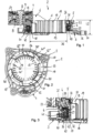
- a belt tensioning device 2 serves to tension an endless belt in a belt drive (not shown).
- an aggregate can be driven via a drive part, for example via a pulley and a drive shaft connected to it in a rotationally fixed manner.
- the belt tensioning device 2 comprises a base body 3, which is attached to the aggregate (not shown) or to a connected component, a clamping arm 4 which is pivotably mounted relative to the base body 3 about a pivot axis A by means of a bearing arrangement 5 and is supported in the circumferential direction relative to the base body 3 via a spring 6.
- the tensioning arm 4 has a tensioning roller 7 on a free end section, which can rotate about an axis of rotation B parallel to the pivot axis A.
- the tensioning roller 7 can also be referred to as a roller carrier.
- the tensioning roller 7 is rotatably mounted on a bearing pin 8 of the tensioning arm 4 and is fastened to it by means of a screw 9. Axially adjacent to the tensioning roller 7, a disk 10 can also be seen, which protects the bearing 12 from penetrating dirt.
- the tensioning arm 4 is rotatably mounted axially and radially relative to the base body 3 about the pivot axis A via the bearing arrangement 5 and is connected to the base body 3 via a connecting arrangement 13.
- the tensioning arm 4 lies at least approximately in the same plane as the bearing arrangement 5, so that the axial installation space is small.
- the spring 6 is designed in the form of a helical spring, the spring center line of which runs essentially parallel to the pivot axis A.
- a first end of the helical spring 6 is bent radially outwards and supported on a corresponding contact surface of the base body 3 in the circumferential direction.
- the opposite second end of the helical spring 6 is also bent radially outwards and supported on a corresponding contact surface of the tensioning arm 4 in the circumferential direction.
- the helical spring 6 causes the tensioning arm 4 to be braced against the base body 3, so that the belt of the belt drive is pre-tensioned.
- the coil spring 6 is arranged coaxially outside the bearing arrangement 5 for the tension arm 4.
- the coil spring 6 and the bearing 5 overlap at least partially in the axial direction in order to keep the installation space in the axial direction small.
- the coil spring has a relatively large diameter in relation to the axial length. The number of turns is greater than one and less than two.
- the circumferential extent of the coil spring is preferably between 540° and 690°.
- the ratio of the nominal diameter D6 of the coil spring 6 to the axial length L6 is, in the installed state of the coil spring, in which the coil spring is axially preloaded, between 3.0 and 9.0, in particular between 5.0 and 8.0. It is understood that the values mentioned are not intended to be restrictive. All intermediate ranges are conceivable within the ranges mentioned. It is also understood that the ratio of spring diameter to axial length in the installed state depends, among other things, on the wire diameter of the spring wire. The larger the wire diameter, the smaller the axial length of the coil spring can be.
- the belt tensioning device 2 or the tensioning arm 4 has a through-opening 18 that is coaxial with the longitudinal axis A.
- the base body 3 can be easily screwed onto an assembly, whereby one end of the drive shaft can optionally be inserted into the through-opening 18.
- a smallest inner diameter D18 of the through-opening is preferably larger than an outer diameter of the drive shaft (not shown) and in particular also larger than an outer diameter of the pulley connected to the drive shaft (not shown).
- the base body 3 has a ring section 25 for supporting the clamping arm 4.
- the ring section 25 is connected radially to the outside by a flange section which serves as an axial support surface 21 for the spring 6.
- Several fastening sections 11 protrude radially outward from the flange section, each of which has a hole for fastening the base body 3 to the connecting component.
- the fastening sections 11 are located on a larger diameter compared to the flange section and compared to the spring 6. This means that torques acting on the base body 3 can be well supported or introduced into the connecting component.
- the helical spring 6 is axially preloaded between the support surface 21 of the base body 3 and an axially opposite support surface 22 of the clamping arm 4 In this way, the tensioning arm 4 is axially acted upon away from the base body 3, whereby the two parts mentioned are axially supported against each other via the connecting arrangement 40.
- the support surface 21 for the spring 6 extends over a circumferential section of the base body 3. At least a section of the support surface 21 lies in a plane which has an axial overlap with the drive shaft.
- the support surface 21 of the base body 3 can have a ramp shape in the circumferential direction which is adapted to the pitch of the coil spring 6.
- the belt tensioning device 2 is designed in such a way that the bearing 5 of the tensioning arm 4 on the base body 3 is located behind the belt plane from the perspective of the unit.
- the belt plane is defined as the plane that is spanned by the center of the belt in the assembled state.
- the bearing arrangement 5 comprises one or more first bearing elements 30 that are assigned to the base body 3 and a second bearing element 31 that is assigned to the tensioning arm 4.
- the ratio of the bearing diameter D5 to the axial length (L2) of the belt tensioner 2 (without tension roller) is greater than 1.5, preferably greater than 2.0.
- the first bearing elements 30 are approximately C-shaped when viewed in a semi-longitudinal section and have a cylindrical section 32 radially inward, from which two flange sections 33, 34 protrude radially outward.
- the first bearing elements 30 engage around the ring section 25 of the base body 3 in a form-fitting manner.
- the first flange section 33 which faces the clamping arm 4, forms an axial bearing surface to support the clamping arm 4 in a first axial direction
- the second flange section 34 which is axially spaced from the first flange section 33, forms an axial bearing surface for the clamping arm 4 in an opposite second axial direction.
- the cylindrical sections 32 form a radial bearing surface for the clamping arm 4.
- the bearing elements 30 and the base body 3 are manufactured in one piece, in particular by means of multi-component injection molding.
- the bearing elements 30 are made of a different plastic material than the base body 3.
- the bearing material is made from a low-friction plastic material, for example from a high-strength polyamide with polytetrafluoroethylene (PTFE) content with a strength of, for example, between 2,000 MPa and 4,000 MPa.
- the base material is made from a fiber-reinforced polyamide with a strength of, for example, between 15,000 MPa and 22,000 MPa.
- the clamping arm 4 has a sleeve section 26 onto which the bearing element 31, which is designed in the form of a bearing bush, is pressed.
- the clamping arm 4 and the bearing bush (insert) are connected to one another over a surface as a hybrid part, so that heat generated during operation is introduced over a surface into the clamping arm 4.
- the bearing bush 31 is in particular a formed sheet metal part and can be made, for example, from aluminum or an aluminum alloy.
- a bushing section 27 of the bearing bush forms a radial bearing with the cylinder sections 32 of the first bearing elements 30, while a flange section 28 of the bearing bush 31 forms an axial bearing with the flange sections 33 of the first bearing elements 30.
- the flange section 28 of the bearing bush 31 and the associated flange section 33 of the first bearing element 30 are in contact with one another over a surface, just as the two flange sections 28, 33 are in contact with the associated components 3, 4 over a surface, so that good heat dissipation from the friction point is possible.
- the same also applies to a lower flange section 29 of the bearing element 31, which is in contact with the clamping arm connection section 42 on the one hand and with the flange section 43 of the bearing element 30 on the other.
- connection arrangement 40 can be seen, with which the clamping arm 4 is connected to the base body 3.
- the connection arrangement 40 is designed in the manner of a bayonet lock and comprises several first connection sections 41, 41', 41", distributed over the circumference, which are assigned to the base body 3, and several second connection sections 42, 42', 42", which interact with them and are assigned to the clamping arm 4.
- a contact surface area is formed between a base body connection section 41, 41', 41" and an associated clamping arm connection section 42, 42', 42".
- a first contact surface area between a first connecting section 41 of the base body 3 and a first connecting section 42 of the clamping arm 4 is larger than the second contact surface area between the second base body connecting section 41' and the second clamping arm connecting section 42' or larger than the third contact surface area between the third base body connecting section 41" and the third clamping arm connecting section 42".
- the area of the mutual overlap between the first connecting sections 41, 42 of the base body 3 and the clamping arm 4 can be more than 20% larger than the overlap area between the second and third connecting sections (41 ⁇ , 42 ⁇ ; 41 ", 42").
- first clamping arm connecting section 42 has a larger circumferential extension than the second and third clamping arm connecting sections 42', 42".
- a recess 43, 43', 43" is formed between two adjacent base body connecting sections 41, 41', 41" in the circumferential direction.
- the clamping arm connecting sections 42, 42', 42" are designed in the form of radial projections corresponding to the recesses 43, 43', 43".
- the clamping arm 4 can thus be axially inserted into the base body 3 in a rotational position in which the radial projections of the clamping arm are arranged in the circumferential areas of the recesses 43, 43', 43" of the base body 3. This makes it possible for the clamping arm 4 and the base body 3 can be connected to each other by a plugging and rotating movement.
- a first relative rotational position which can also be referred to as a bayonet position
- the base body 3 and the clamping arm 4 can be pushed axially into one another. If the projections 42, 42', 42" of the clamping arm 4 are completely guided through the recesses 43, 43', 43", the clamping arm 4 can be rotated relative to the base body 3 into a second relative rotational position. In this second position, the projections 42, 42', 42" of the clamping arm 4 are supported axially on the base body connecting sections 41, 41', 41'' or the bearing elements 30, 30', 30".
- the clamping arm 4 and the base body 3 are axially fixed to one another in this position and are axially preloaded against one another via the spring 6.
- a locking pin (not shown) can be provided which serves as a rotation stop.
- connection arrangement 40 is designed such that the clamping arm 4 and the base body 3 can only be inserted into one another in the first rotational position (bayonet position). This is achieved by arranging the clamping arm connection elements 41, 41', 41" and the base body connection elements 42, 42', 42" irregularly distributed over the circumference and only aligning with one another in exactly one relative rotational position. This design simplifies assembly and prevents incorrect assembly.
- a high-strength fiber-reinforced plastic is preferably used as the base material for the base body 3 and the tension arm 4, for example a glass fiber-reinforced and/or carbon fiber-reinforced polyamide. Reinforcing elements made of a different material are also provided in the base body 3 and the tension arm 4.
- the base body 3 has bushings 16 made of a metal material on the connecting flanges 11, which are overmolded with the plastic.
- the tension arm 4 also has a reinforcing bushing 8 in the form of a bearing pin, which is overmolded with the base material and serves as a carrier for the bearing of the tension roller 7.
- the opening 18 of the tensioning arm 4 is designed in such a way that a drive shaft or pulley of a unit (not shown) can extend into it when assembled.
- the wall 13 of the tensioning arm 4 surrounding the opening 18 is provided with ribs 19 distributed around the circumference.
- the ribs 19 fulfill two functions in particular, namely, firstly, they dissipate frictional heat generated during operation from the tensioning arm 4. Secondly, the ribs 19 support a targeted supply of air in the direction of the unit to which the belt tensioning device is attached in order to cool it effectively.
- the present embodiment is characterized in that the ribs 19 provided on the wall 13 of the tensioning arm 4 have a greater thickness D23 in a foot section 23 than in a head section 24. Due to the thickened foot sections 23, the heat of the tensioning arm 3 can be very well introduced from the wall area into the ribs 19 and from there released to the environment. The excess energy from the tensioning arm 4 is channeled to the surface via the widest possible connection surfaces at the base of the ribs 19. This allows the thermal energy to be collected and released to the environment in a targeted manner by means of convection. This design measure can also be referred to as the "root concept". Overall, the thermal load on the belt tensioner 2 is reduced and the service life is increased accordingly.
- the ribs 19 in the foot section 23 have a variable thickness T over the height H, which is achieved by the fact that the foot sections are rounded when viewed in cross section.
- the height of the foot section 23 with variable thickness is in this case at least 20% of the total height H of the rib 19.
- the ribs 19 have a constant thickness over the height in the head section 24, wherein the height of the head section 24 with constant thickness is in this case at least 50% of the total height H of the rib 19.
- the ribs 19 extend in the axial direction.
- the smallest distance formed in the head section 24 between two ribs 19 adjacent in the circumferential direction is greater than the smallest distance formed in the foot section 23. This ensures good heat dissipation in the head area.
- the ribs 19 are distributed essentially over the entire circumference. Specifically, three segments 20 with 9 ribs 19 each are provided, with a gap being formed between each two rib segments 20.
- the Figure 7 shows a belt tensioning device with a modified rib shape.
- the foot sections 23 are designed in a truncated pyramid shape in cross section (instead of rounded).
- the embodiment according to Figure 7 those according to the Figures 4 to 6 , so that for further details reference is made to the above description. Identical or corresponding details are provided with the same reference numerals as in the Figures 4 to 6 or the Figures 1 to 3 .
- FIG 8 a belt tensioning device is shown in a further embodiment with a further modified rib arrangement.
- This largely corresponds to the embodiment according to Figure 7 , or the Figures 1 to 6 , so that with regard to the similarities, reference is made to the above description. The same or corresponding details are provided with the same reference numerals as in the Figures 1 to 6 .
- the present embodiment according to Figure 8 is characterized in that the wall 13 of the clamping arm 4 is provided with ribs 19 only in a partial circumferential area or has only one rib segment 20. This extends over a circumferential section of slightly more than 90° around the longitudinal axis A.
- the embodiment according to the Figures 1 to 3 which has a connection arrangement with unequal contact surface areas, also with rib arrangements according to one of the embodiments according to the Figures 4 to 8
- the belt tensioning devices can also be provided with a cover disk which is placed from below onto the bearing arrangement 5 or the connecting arrangement 13 in order to protect them from penetrating dirt.
- the belt tensioning device 2 offers the advantage of good heat dissipation and thus a long service life.
Landscapes
- Engineering & Computer Science (AREA)
- General Engineering & Computer Science (AREA)
- Mechanical Engineering (AREA)
- Devices For Conveying Motion By Means Of Endless Flexible Members (AREA)
- Sliding-Contact Bearings (AREA)
Applications Claiming Priority (2)
| Application Number | Priority Date | Filing Date | Title |
|---|---|---|---|
| DE102015115750.0A DE102015115750A1 (de) | 2015-09-17 | 2015-09-17 | Riemenspannvorrichtung |
| EP16188379.8A EP3144563B1 (de) | 2015-09-17 | 2016-09-12 | Riemenspannvorrichtung |
Related Parent Applications (1)
| Application Number | Title | Priority Date | Filing Date |
|---|---|---|---|
| EP16188379.8A Division EP3144563B1 (de) | 2015-09-17 | 2016-09-12 | Riemenspannvorrichtung |
Publications (3)
| Publication Number | Publication Date |
|---|---|
| EP3885609A1 EP3885609A1 (de) | 2021-09-29 |
| EP3885609B1 true EP3885609B1 (de) | 2024-09-04 |
| EP3885609C0 EP3885609C0 (de) | 2024-09-04 |
Family
ID=56920591
Family Applications (2)
| Application Number | Title | Priority Date | Filing Date |
|---|---|---|---|
| EP21168114.3A Active EP3885609B1 (de) | 2015-09-17 | 2016-09-12 | Riemenspannvorrichtung |
| EP16188379.8A Active EP3144563B1 (de) | 2015-09-17 | 2016-09-12 | Riemenspannvorrichtung |
Family Applications After (1)
| Application Number | Title | Priority Date | Filing Date |
|---|---|---|---|
| EP16188379.8A Active EP3144563B1 (de) | 2015-09-17 | 2016-09-12 | Riemenspannvorrichtung |
Country Status (8)
| Country | Link |
|---|---|
| US (1) | US10400871B2 (enExample) |
| EP (2) | EP3885609B1 (enExample) |
| JP (1) | JP7002836B2 (enExample) |
| KR (1) | KR20170033784A (enExample) |
| CN (1) | CN106545628B (enExample) |
| DE (1) | DE102015115750A1 (enExample) |
| ES (2) | ES2877655T3 (enExample) |
| PL (2) | PL3885609T3 (enExample) |
Families Citing this family (8)
| Publication number | Priority date | Publication date | Assignee | Title |
|---|---|---|---|---|
| DE102015215812B4 (de) * | 2015-08-19 | 2020-03-26 | Schaeffler Technologies AG & Co. KG | Riemenspanner |
| DE102016217933B4 (de) * | 2016-09-20 | 2020-06-04 | Schaeffler Technologies AG & Co. KG | Riemenspanner |
| JP2018175091A (ja) * | 2017-04-06 | 2018-11-15 | 株式会社高尾 | 弾球遊技機 |
| JP6883823B2 (ja) * | 2017-04-06 | 2021-06-09 | 株式会社高尾 | 弾球遊技機 |
| IT201700053588A1 (it) * | 2017-05-17 | 2018-11-17 | Dayco Europe Srl | Tenditore per una trasmissione accessori di un autoveicolo |
| DE102018217997B3 (de) | 2018-10-22 | 2019-08-22 | Ford Global Technologies, Llc | Heizbarer Spannarm einer Zugmittelspannvorrichtung eines Zugmitteltriebs eines Kraftfahrzeug-Verbrennungsmotors und Fertigungsverfahren hierfür |
| US11168767B2 (en) * | 2018-10-23 | 2021-11-09 | Gates Corporation | Tensioner |
| KR20200065356A (ko) | 2018-11-30 | 2020-06-09 | 현대자동차주식회사 | 에어컨 컴프레셔 벨트 장력 조절 장치 및 조절 방법 |
Family Cites Families (49)
| Publication number | Priority date | Publication date | Assignee | Title |
|---|---|---|---|---|
| AT313404B (de) * | 1970-03-31 | 1974-02-25 | Staff & Schwarz Gmbh | Elektrische Kupplung zum Verbinden elektrischer Leitungen |
| US4307954A (en) * | 1980-08-18 | 1981-12-29 | Ludwig Robert B | Bayonet mount |
| US4478492A (en) * | 1981-11-18 | 1984-10-23 | Minolta Camera Kabushiki Kaisha | Optical device with bayonet mount and position restriction means |
| US5042257A (en) * | 1989-05-01 | 1991-08-27 | Kendrick Julia S | Double extruded heat sink |
| DE4015028A1 (de) * | 1990-05-10 | 1992-01-16 | Skf Gmbh | Voreinstellbare spannvorrichtung |
| US5190502A (en) * | 1992-02-07 | 1993-03-02 | Dayco Products, Inc. | Belt tensioning system, belt tensioner therefor and methods of making the same |
| CA2087763C (en) * | 1992-02-11 | 2002-07-02 | Jimmy Cochimin | Stator frame for dynamoelectric machine and method for making same |
| JP2765801B2 (ja) * | 1993-08-20 | 1998-06-18 | 山洋電気株式会社 | 電子部品冷却装置 |
| US5718649A (en) * | 1996-02-16 | 1998-02-17 | Dayco Products, Inc. | Tensioner for a power transmission belt and method of making same |
| US5787971A (en) * | 1996-03-25 | 1998-08-04 | Dodson; Douglas A. | Multiple fan cooling device |
| US5734554A (en) * | 1996-07-01 | 1998-03-31 | Sun Microsystems, Inc. | Heat sink and fan for cooling CPU chip |
| DE19729994A1 (de) * | 1997-07-12 | 1999-01-14 | Skf Gmbh | Spannvorrichtung für Treibriemen |
| US5937517A (en) * | 1997-11-12 | 1999-08-17 | Eastman Kodak Company | Method of manufacturing bonded dual extruded, high fin density heat sinks |
| US6009938A (en) * | 1997-12-11 | 2000-01-04 | Eastman Kodak Company | Extruded, tiered high fin density heat sinks and method of manufacture |
| JP3454707B2 (ja) * | 1998-03-31 | 2003-10-06 | 山洋電気株式会社 | 電子部品冷却装置 |
| DE69819194T2 (de) * | 1998-07-01 | 2004-06-09 | Mitsubishi Denki K.K. | Wechselstromgenerator für fahrzeuge und dessen integrierter kühlkörper |
| US6217470B1 (en) * | 1999-08-13 | 2001-04-17 | Dayco Products, Inc. | Belt tensioner with increased bushing surface |
| WO2001044869A1 (en) * | 1999-12-16 | 2001-06-21 | Nikon Corporation | Bayonet mount |
| US6452800B2 (en) * | 1999-12-29 | 2002-09-17 | Hon Hai Precision Ind., Co., Ltd. | Heat sink assembly for dissipating heat of an electronic package mounted on an electrical socket |
| US6313994B1 (en) * | 2000-07-25 | 2001-11-06 | Sun Microsystems, Inc. | Extended surface area heat sink |
| US6310771B1 (en) * | 2000-11-14 | 2001-10-30 | Chuan-Fu Chien | CPU heat sink |
| US6404634B1 (en) * | 2000-12-06 | 2002-06-11 | Hewlett-Packard Company | Single piece heat sink for computer chip |
| US7588507B2 (en) * | 2001-04-13 | 2009-09-15 | Unitta Company | Thin autotensioner |
| US20040182542A1 (en) * | 2001-04-23 | 2004-09-23 | Koichiro Take | Heat sink |
| US7186196B2 (en) * | 2002-07-18 | 2007-03-06 | Dayco Products, Llc | Belt tensioner with integral damping |
| US6855079B2 (en) * | 2002-09-30 | 2005-02-15 | Fenner, Inc. | Bi-directional belt tensioner |
| DE10333876A1 (de) * | 2003-07-25 | 2005-02-17 | Ina-Schaeffler Kg | Spann- oder Umlenkelement eines Zugmitteltriebs |
| KR101322173B1 (ko) * | 2006-03-22 | 2013-10-25 | 리텐스 오토모티브 파트너쉽 | 플렉서블 드라이브를 위한 텐셔너 |
| FR2907526B1 (fr) * | 2006-10-20 | 2009-06-26 | Skf Ab | Dispositif de galet tendeur ou enrouleur. |
| JP5157210B2 (ja) * | 2007-03-20 | 2013-03-06 | オイレス工業株式会社 | スラスト滑り軸受並びにこのスラスト滑り軸受とピストンロッド及びコイルばねとの組合せ機構 |
| US20080308364A1 (en) * | 2007-06-13 | 2008-12-18 | Webb Wheel Products, Inc. | Lightweight brake drum with middle position squealer band |
| CN101435566A (zh) * | 2007-11-16 | 2009-05-20 | 富准精密工业(深圳)有限公司 | 发光二极管灯具 |
| US8279033B2 (en) * | 2008-01-25 | 2012-10-02 | Tech Design, L.L.C. | Transformer with isolated cells |
| DE102008052727A1 (de) * | 2008-10-22 | 2010-05-06 | Schaeffler Kg | Spannvorrichtung für Zugmittel |
| CN201297603Y (zh) * | 2008-11-11 | 2009-08-26 | 东莞乐域塑胶电子制品有限公司 | 一种路灯的散热座 |
| CN101868134A (zh) * | 2009-04-14 | 2010-10-20 | 鸿富锦精密工业(深圳)有限公司 | 散热器及其制造方法 |
| TWM363192U (en) * | 2009-04-17 | 2009-08-11 | chong-xian Huang | Heat dissipating device |
| JP5369989B2 (ja) * | 2009-08-17 | 2013-12-18 | リコーイメージング株式会社 | レンズ鏡筒の防滴バヨネット構造 |
| US8413713B2 (en) * | 2010-05-27 | 2013-04-09 | Tsung-Hsien Huang | Heat sink module with fins having Z shaped foot portions |
| US8545352B2 (en) * | 2010-09-02 | 2013-10-01 | Dayco Ip Holdings, Llc | Tensioner with expanding spring for radial frictional asymmetric damping |
| DE102011003113A1 (de) * | 2011-01-25 | 2012-07-26 | Schaeffler Technologies Gmbh & Co. Kg | Zugmittelspannvorrichtung mit einem Gehäuse, das einen Kühlkörper aufweist |
| EP2676304B1 (en) * | 2011-02-16 | 2018-09-19 | Caframo Limited | Thermally driven power generator |
| DE102011080509A1 (de) * | 2011-08-05 | 2013-02-07 | Schaeffler Technologies AG & Co. KG | Riemenspanner |
| DE102011053869B4 (de) * | 2011-09-22 | 2020-03-26 | Muhr Und Bender Kg | Riemenspannvorrichtung für einen Riementrieb und Aggregatanordnung mit Riemenspannvorrichtung |
| WO2013055018A1 (ko) * | 2011-10-11 | 2013-04-18 | 주식회사 포스코엘이디 | 광 반도체 조명장치 |
| DE102013102562B4 (de) * | 2013-03-13 | 2021-05-27 | Muhr Und Bender Kg | Verwendung einer Feder in einer Riemenspannvorrichtung, Riemenspannvorrichtung und Aggregatanordnung |
| DE102014206716A1 (de) | 2014-04-08 | 2015-10-08 | Muhr Und Bender Kg | Riemenspannvorrichtung |
| AT515828B1 (de) * | 2014-05-23 | 2022-02-15 | Fronius Int Gmbh | Kühlvorrichtung und Wechselrichtergehäuse mit einer solchen Kühlvorrichtung |
| WO2016057582A1 (en) * | 2014-10-08 | 2016-04-14 | Remy Technologies, Llc | Axially extending electric machine electronics cooling tower |
-
2015
- 2015-09-17 DE DE102015115750.0A patent/DE102015115750A1/de active Pending
-
2016
- 2016-09-12 ES ES16188379T patent/ES2877655T3/es active Active
- 2016-09-12 EP EP21168114.3A patent/EP3885609B1/de active Active
- 2016-09-12 PL PL21168114.3T patent/PL3885609T3/pl unknown
- 2016-09-12 PL PL16188379T patent/PL3144563T3/pl unknown
- 2016-09-12 EP EP16188379.8A patent/EP3144563B1/de active Active
- 2016-09-12 US US15/262,101 patent/US10400871B2/en active Active
- 2016-09-12 ES ES21168114T patent/ES2993584T3/es active Active
- 2016-09-13 KR KR1020160117765A patent/KR20170033784A/ko not_active Withdrawn
- 2016-09-16 JP JP2016181560A patent/JP7002836B2/ja active Active
- 2016-09-18 CN CN201610828158.7A patent/CN106545628B/zh active Active
Also Published As
| Publication number | Publication date |
|---|---|
| DE102015115750A1 (de) | 2017-03-23 |
| EP3144563A2 (de) | 2017-03-22 |
| EP3144563A3 (de) | 2017-04-12 |
| US10400871B2 (en) | 2019-09-03 |
| KR20170033784A (ko) | 2017-03-27 |
| US20170082176A1 (en) | 2017-03-23 |
| CN106545628A (zh) | 2017-03-29 |
| PL3144563T3 (pl) | 2021-11-29 |
| CN106545628B (zh) | 2021-06-29 |
| EP3885609A1 (de) | 2021-09-29 |
| JP7002836B2 (ja) | 2022-01-20 |
| EP3144563B1 (de) | 2021-05-05 |
| ES2993584T3 (en) | 2025-01-02 |
| JP2017075697A (ja) | 2017-04-20 |
| ES2877655T3 (es) | 2021-11-17 |
| PL3885609T3 (pl) | 2025-01-27 |
| EP3885609C0 (de) | 2024-09-04 |
Similar Documents
| Publication | Publication Date | Title |
|---|---|---|
| EP3885609B1 (de) | Riemenspannvorrichtung | |
| EP3023670B1 (de) | Riemenspannvorrichtung | |
| EP2778472B1 (de) | Feder, Riemenspannvorrichtung und Aggregatanordnung | |
| EP3431815B1 (de) | Riemenspannvorrichtung | |
| EP2957793A2 (de) | Riemenspannvorrichtung | |
| EP3477154B1 (de) | Spannvorrichtung | |
| EP3121484B1 (de) | Spannvorrichtung | |
| WO2009003829A2 (de) | Dämpfungsvorrichtung eines mechanischen spannsystems für einen zugmitteltrieb | |
| EP3374666B1 (de) | Spielfreie pendellagerung am entkopplungsspanner | |
| EP2573423A1 (de) | Riemenspannvorrichtung für einen Riementrieb und Aggregatanordnung mit Riemenspannvorrichtung | |
| EP2385272B1 (de) | Spanner und Endlostriebanordnung | |
| DE102016219919A1 (de) | Elastisches Zahnrad eines Wellgetriebes | |
| DE102017107047A1 (de) | Spannvorrichtung mit Verstellmechanismus und Verfahren zum Einstellen des Drehmoments der Spannvorrichtung | |
| DE102010019066A1 (de) | Riemenspanner | |
| WO2012143219A1 (de) | Riemenspanner | |
| WO2008074577A1 (de) | Spannvorrichtung für einen zugmitteltrieb | |
| DE102011088213A1 (de) | Spannanordnung für einen Zugmitteltrieb | |
| DE102004041044A1 (de) | Drehpunktlagerung eines Aggregates | |
| EP2621756B1 (de) | Verstelleinrichtung mit einem spindelgetriebe | |
| DE102020004335A1 (de) | Riemenspannvorrichtung und Riementrieb mit einer solchen Riemenspannvorrichtung | |
| WO2001084014A1 (de) | Spannsystem mit einer gerichteten dämpfung | |
| DE102007020738A1 (de) | Spannvorrichtung für einen Zugmitteltrieb | |
| WO2012097887A1 (de) | Spanneinrichtung | |
| EP3748193A2 (de) | Spannanordnung mit spannrolle und vorrichtung zum einstellen einer spannanordnung | |
| DE10360286A1 (de) | Riemenspanneinrichtung |
Legal Events
| Date | Code | Title | Description |
|---|---|---|---|
| PUAI | Public reference made under article 153(3) epc to a published international application that has entered the european phase |
Free format text: ORIGINAL CODE: 0009012 |
|
| STAA | Information on the status of an ep patent application or granted ep patent |
Free format text: STATUS: THE APPLICATION HAS BEEN PUBLISHED |
|
| AC | Divisional application: reference to earlier application |
Ref document number: 3144563 Country of ref document: EP Kind code of ref document: P |
|
| AK | Designated contracting states |
Kind code of ref document: A1 Designated state(s): AL AT BE BG CH CY CZ DE DK EE ES FI FR GB GR HR HU IE IS IT LI LT LU LV MC MK MT NL NO PL PT RO RS SE SI SK SM TR |
|
| STAA | Information on the status of an ep patent application or granted ep patent |
Free format text: STATUS: REQUEST FOR EXAMINATION WAS MADE |
|
| 17P | Request for examination filed |
Effective date: 20220215 |
|
| RBV | Designated contracting states (corrected) |
Designated state(s): AL AT BE BG CH CY CZ DE DK EE ES FI FR GB GR HR HU IE IS IT LI LT LU LV MC MK MT NL NO PL PT RO RS SE SI SK SM TR |
|
| STAA | Information on the status of an ep patent application or granted ep patent |
Free format text: STATUS: EXAMINATION IS IN PROGRESS |
|
| 17Q | First examination report despatched |
Effective date: 20220509 |
|
| GRAP | Despatch of communication of intention to grant a patent |
Free format text: ORIGINAL CODE: EPIDOSNIGR1 |
|
| STAA | Information on the status of an ep patent application or granted ep patent |
Free format text: STATUS: GRANT OF PATENT IS INTENDED |
|
| INTG | Intention to grant announced |
Effective date: 20240325 |
|
| GRAS | Grant fee paid |
Free format text: ORIGINAL CODE: EPIDOSNIGR3 |
|
| GRAA | (expected) grant |
Free format text: ORIGINAL CODE: 0009210 |
|
| STAA | Information on the status of an ep patent application or granted ep patent |
Free format text: STATUS: THE PATENT HAS BEEN GRANTED |
|
| AC | Divisional application: reference to earlier application |
Ref document number: 3144563 Country of ref document: EP Kind code of ref document: P |
|
| AK | Designated contracting states |
Kind code of ref document: B1 Designated state(s): AL AT BE BG CH CY CZ DE DK EE ES FI FR GB GR HR HU IE IS IT LI LT LU LV MC MK MT NL NO PL PT RO RS SE SI SK SM TR |
|
| REG | Reference to a national code |
Ref country code: GB Ref legal event code: FG4D Free format text: NOT ENGLISH |
|
| REG | Reference to a national code |
Ref country code: CH Ref legal event code: EP |
|
| REG | Reference to a national code |
Ref country code: IE Ref legal event code: FG4D Free format text: LANGUAGE OF EP DOCUMENT: GERMAN |
|
| REG | Reference to a national code |
Ref country code: DE Ref legal event code: R096 Ref document number: 502016016713 Country of ref document: DE |
|
| U01 | Request for unitary effect filed |
Effective date: 20241001 |
|
| U07 | Unitary effect registered |
Designated state(s): AT BE BG DE DK EE FI FR IT LT LU LV MT NL PT RO SE SI Effective date: 20241024 |
|
| REG | Reference to a national code |
Ref country code: ES Ref legal event code: FG2A Ref document number: 2993584 Country of ref document: ES Kind code of ref document: T3 Effective date: 20250102 |
|
| PG25 | Lapsed in a contracting state [announced via postgrant information from national office to epo] |
Ref country code: NO Free format text: LAPSE BECAUSE OF FAILURE TO SUBMIT A TRANSLATION OF THE DESCRIPTION OR TO PAY THE FEE WITHIN THE PRESCRIBED TIME-LIMIT Effective date: 20241204 |
|
| REG | Reference to a national code |
Ref country code: SK Ref legal event code: T3 Ref document number: E 45424 Country of ref document: SK |
|
| PG25 | Lapsed in a contracting state [announced via postgrant information from national office to epo] |
Ref country code: GR Free format text: LAPSE BECAUSE OF FAILURE TO SUBMIT A TRANSLATION OF THE DESCRIPTION OR TO PAY THE FEE WITHIN THE PRESCRIBED TIME-LIMIT Effective date: 20241205 |
|
| PG25 | Lapsed in a contracting state [announced via postgrant information from national office to epo] |
Ref country code: HR Free format text: LAPSE BECAUSE OF FAILURE TO SUBMIT A TRANSLATION OF THE DESCRIPTION OR TO PAY THE FEE WITHIN THE PRESCRIBED TIME-LIMIT Effective date: 20240904 |
|
| PG25 | Lapsed in a contracting state [announced via postgrant information from national office to epo] |
Ref country code: RS Free format text: LAPSE BECAUSE OF FAILURE TO SUBMIT A TRANSLATION OF THE DESCRIPTION OR TO PAY THE FEE WITHIN THE PRESCRIBED TIME-LIMIT Effective date: 20241204 |
|
| PG25 | Lapsed in a contracting state [announced via postgrant information from national office to epo] |
Ref country code: RS Free format text: LAPSE BECAUSE OF FAILURE TO SUBMIT A TRANSLATION OF THE DESCRIPTION OR TO PAY THE FEE WITHIN THE PRESCRIBED TIME-LIMIT Effective date: 20241204 Ref country code: NO Free format text: LAPSE BECAUSE OF FAILURE TO SUBMIT A TRANSLATION OF THE DESCRIPTION OR TO PAY THE FEE WITHIN THE PRESCRIBED TIME-LIMIT Effective date: 20241204 Ref country code: HR Free format text: LAPSE BECAUSE OF FAILURE TO SUBMIT A TRANSLATION OF THE DESCRIPTION OR TO PAY THE FEE WITHIN THE PRESCRIBED TIME-LIMIT Effective date: 20240904 Ref country code: GR Free format text: LAPSE BECAUSE OF FAILURE TO SUBMIT A TRANSLATION OF THE DESCRIPTION OR TO PAY THE FEE WITHIN THE PRESCRIBED TIME-LIMIT Effective date: 20241205 |
|
| U21 | Renewal fee for the european patent with unitary effect paid with additional fee |
Year of fee payment: 9 Effective date: 20250218 |
|
| PG25 | Lapsed in a contracting state [announced via postgrant information from national office to epo] |
Ref country code: IS Free format text: LAPSE BECAUSE OF FAILURE TO SUBMIT A TRANSLATION OF THE DESCRIPTION OR TO PAY THE FEE WITHIN THE PRESCRIBED TIME-LIMIT Effective date: 20250104 |
|
| PG25 | Lapsed in a contracting state [announced via postgrant information from national office to epo] |
Ref country code: SM Free format text: LAPSE BECAUSE OF FAILURE TO SUBMIT A TRANSLATION OF THE DESCRIPTION OR TO PAY THE FEE WITHIN THE PRESCRIBED TIME-LIMIT Effective date: 20240904 |
|
| REG | Reference to a national code |
Ref country code: CH Ref legal event code: PL |
|
| PG25 | Lapsed in a contracting state [announced via postgrant information from national office to epo] |
Ref country code: MC Free format text: LAPSE BECAUSE OF FAILURE TO SUBMIT A TRANSLATION OF THE DESCRIPTION OR TO PAY THE FEE WITHIN THE PRESCRIBED TIME-LIMIT Effective date: 20240904 |
|
| PLBE | No opposition filed within time limit |
Free format text: ORIGINAL CODE: 0009261 |
|
| STAA | Information on the status of an ep patent application or granted ep patent |
Free format text: STATUS: NO OPPOSITION FILED WITHIN TIME LIMIT |
|
| PG25 | Lapsed in a contracting state [announced via postgrant information from national office to epo] |
Ref country code: CH Free format text: LAPSE BECAUSE OF NON-PAYMENT OF DUE FEES Effective date: 20240930 |
|
| PG25 | Lapsed in a contracting state [announced via postgrant information from national office to epo] |
Ref country code: IE Free format text: LAPSE BECAUSE OF NON-PAYMENT OF DUE FEES Effective date: 20240912 |
|
| 26N | No opposition filed |
Effective date: 20250605 |
|
| GBPC | Gb: european patent ceased through non-payment of renewal fee |
Effective date: 20241204 |
|
| PGFP | Annual fee paid to national office [announced via postgrant information from national office to epo] |
Ref country code: PL Payment date: 20250908 Year of fee payment: 10 |
|
| U20 | Renewal fee for the european patent with unitary effect paid |
Year of fee payment: 10 Effective date: 20250905 |
|
| PG25 | Lapsed in a contracting state [announced via postgrant information from national office to epo] |
Ref country code: GB Free format text: LAPSE BECAUSE OF NON-PAYMENT OF DUE FEES Effective date: 20241204 |
|
| PGFP | Annual fee paid to national office [announced via postgrant information from national office to epo] |
Ref country code: CZ Payment date: 20250815 Year of fee payment: 10 |
|
| PGFP | Annual fee paid to national office [announced via postgrant information from national office to epo] |
Ref country code: SK Payment date: 20250818 Year of fee payment: 10 |
|
| PG25 | Lapsed in a contracting state [announced via postgrant information from national office to epo] |
Ref country code: CY Free format text: LAPSE BECAUSE OF FAILURE TO SUBMIT A TRANSLATION OF THE DESCRIPTION OR TO PAY THE FEE WITHIN THE PRESCRIBED TIME-LIMIT; INVALID AB INITIO Effective date: 20160912 |
|
| PGFP | Annual fee paid to national office [announced via postgrant information from national office to epo] |
Ref country code: ES Payment date: 20251002 Year of fee payment: 10 |
|
| PG25 | Lapsed in a contracting state [announced via postgrant information from national office to epo] |
Ref country code: HU Free format text: LAPSE BECAUSE OF FAILURE TO SUBMIT A TRANSLATION OF THE DESCRIPTION OR TO PAY THE FEE WITHIN THE PRESCRIBED TIME-LIMIT; INVALID AB INITIO Effective date: 20160912 |