EP3885535B1 - Dichtring für einen rotor und rotor mit einem solchen - Google Patents
Dichtring für einen rotor und rotor mit einem solchen Download PDFInfo
- Publication number
- EP3885535B1 EP3885535B1 EP20165112.2A EP20165112A EP3885535B1 EP 3885535 B1 EP3885535 B1 EP 3885535B1 EP 20165112 A EP20165112 A EP 20165112A EP 3885535 B1 EP3885535 B1 EP 3885535B1
- Authority
- EP
- European Patent Office
- Prior art keywords
- section
- edge
- washer
- face
- sealing washer
- Prior art date
- Legal status (The legal status is an assumption and is not a legal conclusion. Google has not performed a legal analysis and makes no representation as to the accuracy of the status listed.)
- Active
Links
Images

Classifications
-
- F—MECHANICAL ENGINEERING; LIGHTING; HEATING; WEAPONS; BLASTING
- F01—MACHINES OR ENGINES IN GENERAL; ENGINE PLANTS IN GENERAL; STEAM ENGINES
- F01D—NON-POSITIVE DISPLACEMENT MACHINES OR ENGINES, e.g. STEAM TURBINES
- F01D11/00—Preventing or minimising internal leakage of working-fluid, e.g. between stages
- F01D11/005—Sealing means between non relatively rotating elements
- F01D11/006—Sealing the gap between rotor blades or blades and rotor
-
- F—MECHANICAL ENGINEERING; LIGHTING; HEATING; WEAPONS; BLASTING
- F01—MACHINES OR ENGINES IN GENERAL; ENGINE PLANTS IN GENERAL; STEAM ENGINES
- F01D—NON-POSITIVE DISPLACEMENT MACHINES OR ENGINES, e.g. STEAM TURBINES
- F01D5/00—Blades; Blade-carrying members; Heating, heat-insulating, cooling or antivibration means on the blades or the members
- F01D5/30—Fixing blades to rotors; Blade roots ; Blade spacers
- F01D5/3007—Fixing blades to rotors; Blade roots ; Blade spacers of axial insertion type
-
- F—MECHANICAL ENGINEERING; LIGHTING; HEATING; WEAPONS; BLASTING
- F16—ENGINEERING ELEMENTS AND UNITS; GENERAL MEASURES FOR PRODUCING AND MAINTAINING EFFECTIVE FUNCTIONING OF MACHINES OR INSTALLATIONS; THERMAL INSULATION IN GENERAL
- F16J—PISTONS; CYLINDERS; SEALINGS
- F16J15/00—Sealings
- F16J15/16—Sealings between relatively-moving surfaces
- F16J15/32—Sealings between relatively-moving surfaces with elastic sealings, e.g. O-rings
- F16J15/3268—Mounting of sealing rings
-
- F—MECHANICAL ENGINEERING; LIGHTING; HEATING; WEAPONS; BLASTING
- F01—MACHINES OR ENGINES IN GENERAL; ENGINE PLANTS IN GENERAL; STEAM ENGINES
- F01D—NON-POSITIVE DISPLACEMENT MACHINES OR ENGINES, e.g. STEAM TURBINES
- F01D11/00—Preventing or minimising internal leakage of working-fluid, e.g. between stages
- F01D11/003—Preventing or minimising internal leakage of working-fluid, e.g. between stages by packing rings; Mechanical seals
-
- F—MECHANICAL ENGINEERING; LIGHTING; HEATING; WEAPONS; BLASTING
- F01—MACHINES OR ENGINES IN GENERAL; ENGINE PLANTS IN GENERAL; STEAM ENGINES
- F01D—NON-POSITIVE DISPLACEMENT MACHINES OR ENGINES, e.g. STEAM TURBINES
- F01D5/00—Blades; Blade-carrying members; Heating, heat-insulating, cooling or antivibration means on the blades or the members
- F01D5/02—Blade-carrying members, e.g. rotors
-
- F—MECHANICAL ENGINEERING; LIGHTING; HEATING; WEAPONS; BLASTING
- F16—ENGINEERING ELEMENTS AND UNITS; GENERAL MEASURES FOR PRODUCING AND MAINTAINING EFFECTIVE FUNCTIONING OF MACHINES OR INSTALLATIONS; THERMAL INSULATION IN GENERAL
- F16J—PISTONS; CYLINDERS; SEALINGS
- F16J15/00—Sealings
- F16J15/16—Sealings between relatively-moving surfaces
- F16J15/32—Sealings between relatively-moving surfaces with elastic sealings, e.g. O-rings
- F16J15/3284—Sealings between relatively-moving surfaces with elastic sealings, e.g. O-rings characterised by their structure; Selection of materials
-
- F—MECHANICAL ENGINEERING; LIGHTING; HEATING; WEAPONS; BLASTING
- F01—MACHINES OR ENGINES IN GENERAL; ENGINE PLANTS IN GENERAL; STEAM ENGINES
- F01D—NON-POSITIVE DISPLACEMENT MACHINES OR ENGINES, e.g. STEAM TURBINES
- F01D5/00—Blades; Blade-carrying members; Heating, heat-insulating, cooling or antivibration means on the blades or the members
- F01D5/30—Fixing blades to rotors; Blade roots ; Blade spacers
- F01D5/3007—Fixing blades to rotors; Blade roots ; Blade spacers of axial insertion type
- F01D5/3015—Fixing blades to rotors; Blade roots ; Blade spacers of axial insertion type with side plates
-
- F—MECHANICAL ENGINEERING; LIGHTING; HEATING; WEAPONS; BLASTING
- F05—INDEXING SCHEMES RELATING TO ENGINES OR PUMPS IN VARIOUS SUBCLASSES OF CLASSES F01-F04
- F05D—INDEXING SCHEME FOR ASPECTS RELATING TO NON-POSITIVE-DISPLACEMENT MACHINES OR ENGINES, GAS-TURBINES OR JET-PROPULSION PLANTS
- F05D2220/00—Application
- F05D2220/30—Application in turbines
- F05D2220/32—Application in turbines in gas turbines
-
- F—MECHANICAL ENGINEERING; LIGHTING; HEATING; WEAPONS; BLASTING
- F05—INDEXING SCHEMES RELATING TO ENGINES OR PUMPS IN VARIOUS SUBCLASSES OF CLASSES F01-F04
- F05D—INDEXING SCHEME FOR ASPECTS RELATING TO NON-POSITIVE-DISPLACEMENT MACHINES OR ENGINES, GAS-TURBINES OR JET-PROPULSION PLANTS
- F05D2240/00—Components
- F05D2240/20—Rotors
- F05D2240/30—Characteristics of rotor blades, i.e. of any element transforming dynamic fluid energy to or from rotational energy and being attached to a rotor
-
- F—MECHANICAL ENGINEERING; LIGHTING; HEATING; WEAPONS; BLASTING
- F05—INDEXING SCHEMES RELATING TO ENGINES OR PUMPS IN VARIOUS SUBCLASSES OF CLASSES F01-F04
- F05D—INDEXING SCHEME FOR ASPECTS RELATING TO NON-POSITIVE-DISPLACEMENT MACHINES OR ENGINES, GAS-TURBINES OR JET-PROPULSION PLANTS
- F05D2240/00—Components
- F05D2240/55—Seals
-
- F—MECHANICAL ENGINEERING; LIGHTING; HEATING; WEAPONS; BLASTING
- F05—INDEXING SCHEMES RELATING TO ENGINES OR PUMPS IN VARIOUS SUBCLASSES OF CLASSES F01-F04
- F05D—INDEXING SCHEME FOR ASPECTS RELATING TO NON-POSITIVE-DISPLACEMENT MACHINES OR ENGINES, GAS-TURBINES OR JET-PROPULSION PLANTS
- F05D2250/00—Geometry
- F05D2250/10—Two-dimensional
- F05D2250/11—Two-dimensional triangular
-
- F—MECHANICAL ENGINEERING; LIGHTING; HEATING; WEAPONS; BLASTING
- F05—INDEXING SCHEMES RELATING TO ENGINES OR PUMPS IN VARIOUS SUBCLASSES OF CLASSES F01-F04
- F05D—INDEXING SCHEME FOR ASPECTS RELATING TO NON-POSITIVE-DISPLACEMENT MACHINES OR ENGINES, GAS-TURBINES OR JET-PROPULSION PLANTS
- F05D2250/00—Geometry
- F05D2250/10—Two-dimensional
- F05D2250/13—Two-dimensional trapezoidal
-
- F—MECHANICAL ENGINEERING; LIGHTING; HEATING; WEAPONS; BLASTING
- F05—INDEXING SCHEMES RELATING TO ENGINES OR PUMPS IN VARIOUS SUBCLASSES OF CLASSES F01-F04
- F05D—INDEXING SCHEME FOR ASPECTS RELATING TO NON-POSITIVE-DISPLACEMENT MACHINES OR ENGINES, GAS-TURBINES OR JET-PROPULSION PLANTS
- F05D2250/00—Geometry
- F05D2250/10—Two-dimensional
- F05D2250/18—Two-dimensional patterned
- F05D2250/182—Two-dimensional patterned crenellated, notched
-
- F—MECHANICAL ENGINEERING; LIGHTING; HEATING; WEAPONS; BLASTING
- F05—INDEXING SCHEMES RELATING TO ENGINES OR PUMPS IN VARIOUS SUBCLASSES OF CLASSES F01-F04
- F05D—INDEXING SCHEME FOR ASPECTS RELATING TO NON-POSITIVE-DISPLACEMENT MACHINES OR ENGINES, GAS-TURBINES OR JET-PROPULSION PLANTS
- F05D2260/00—Function
- F05D2260/30—Retaining components in desired mutual position
- F05D2260/36—Retaining components in desired mutual position by a form fit connection, e.g. by interlocking
Definitions
- the invention relates to a two-part or multi-part sealing ring for use in a rotor, in particular in a gas turbine, with the ends of the sealing ring overlapping in order to reduce leakage through the gap that is formed. It is provided that the sealing ring causes a seal against other rotor components by means of centrifugal force. In the type presented here, the cross section of the sealing ring is very small compared to its diameter.
- a sealing ring is known from the prior art, which has two sealing surfaces which are arranged at an angle to one another and which cause a gap to be sealed when the rotor rotates by means of centrifugal force.
- one of the two sealing surfaces is in contact with a rotor component on one side of the gap and the other sealing surface is in contact with another rotor component on the other side of the gap.
- the document EP 2 453 150 A1 discloses a sealing ring comprising the technical features of the preamble of independent claim 1.
- the sealing ring Due to the multi-part design of the sealing ring, the ends of the individual sealing ring segments overlap so that no new gap remains open between the sealing ring segments. Due to the relatively small cross-section, the sealing ring is basically divided in half on the middle radius in the overlapping sections, so that both sections lying on top of one another have sufficient rigidity.
- a disadvantage of the known embodiment is that there remains a gap, albeit a very small one, that is not completely sealed at the overlap.
- the known embodiment means that one of the two sections only partially encompasses one of the two sealing surfaces, but has no seal on the other sealing surface.
- the object of the present invention is therefore to further improve the sealing by means of a sealing ring.
- the generic sealing ring is initially used in a rotor to seal a circumferential gap between different rotor components. What type of rotor is involved is initially irrelevant, with use being particularly appropriate in a gas turbine.
- the sealing ring or the rotor defines a rotor axis.
- the sealing ring has a contact surface which extends approximately radially and in the circumferential direction. This is considered to be the case when the angle between the contact surface and a radial direction is a maximum of 15°.
- the contact surface is delimited on the side pointing towards the rotor axis by an inner contact edge and on the side pointing radially outwards by an outer contact edge.
- the sealing ring has a supporting surface aligned at an angle to the rotor axis. It is provided here that an angle between the support surface and the rotor axis is at least 15°, but at most 45°. Viewed in the direction of the rotor axis, the support surface is delimited on one side by a front support edge and on the opposite side by a rear support edge. In this case, the front support edge is on the side facing the contact surface, while the rear support edge is on the side facing away from the contact surface on the sealing ring.
- the sealing ring comprises at least one ring section with a substantially constant cross section. Furthermore, the sealing ring has a pressing section and a triangular section.
- the pressing section is integrally connected to a first section end of the ring section in the circumferential direction.
- the triangular section is integrally connected at a second section end to a ring section, which may be the same ring section as before or a different ring section. This creates a separation point. It is provided that at the at least one separation point the pressing section overlaps the triangular section in the circumferential direction and thus forms an overlapping area.
- a gap remains between the free end of the pressing section and the second end of the section and also between the free end of the triangular section and the first end of the section.
- the gaps are necessary here in order to allow tolerance compensation and different thermal expansions of the rotor components and the sealing ring.
- the gaps can be structurally provided with the same dimensions.
- the separation between the triangular section and the pressing section forms a separating surface. Viewed in the axial direction, the separating surface is delimited on the one hand by a lower separating surface edge and opposite by an upper separating surface edge.
- the lower edge of the parting surface is generically located between the center of the contact surface and the inner contact edge of the contact surface.
- both the triangular section and the pressing section have the contact surface in sections. If it is ensured that both the triangular section and the pressing section rest reliably on the adjacent rotor component with the contact surface, the tightness at this point is essentially guaranteed.
- the separating surface is now aligned in the opposite direction to the support surface and an unequal distribution between the triangular section and the support section is accepted.
- the cross-sectional area of the triangular section corresponds to only up to 0.3 times the cross-sectional area of the annular section. Consequently, the cross section of the pressing section is at least twice the cross-sectional area of the triangular section. This leads to the possibility of locating the top parting edge in an area between the center of the support surface and the rear support edge.
- the embodiment according to the invention makes it possible to also provide the triangular section and the pressing section as overlapping sections of the sealing ring with at least a portion of the support surface, so that a seal can also be essentially guaranteed in this area. A leakage in the area of the overlap can thus be further reduced compared to the embodiment in the prior art.
- Sealing by means of the sealing ring is advantageously ensured if the corresponding sealing surfaces have a sufficient width.
- the sealing surface is as wide as possible.
- the contact surface has a contact height from the lower contact edge to the upper contact edge, measured in the radial direction, of at least 0.5 times the height of the sealing ring, also measured as a dimension in the radial direction. It is the same
- the support surface has a support width from the rear support edge to the front support edge, measured in the axial direction, of at least 0.5 times the width of the sealing ring, also measured in the axial direction.
- the lower edge of the parting surface is arranged in the vicinity of the inner bearing edge, the distance from the center of the bearing surface being greater than the distance from the inner bearing edge.
- the upper edge of the parting surface is arranged in the vicinity of the rear supporting edge.
- the distance between the upper edge of the parting surface and the rear supporting edge should be selected to be less than the distance between the upper edge of the parting surface and the center of the supporting surface.
- the separating surface is oriented inclined in the opposite direction to the supporting surface.
- an angle between the separating surface and the radial direction is between 35° and 55°. From this it follows that the advantageous angle between the parting surface and the rotor axis is also between 35° and 55°.
- the angle between the separating surface and the radial direction or between the separating surface and the rotor axis is between 40° and 50° and is arranged diagonally—in the opposite direction to the support surface.
- the sealing ring is advantageously formed by at least two ring segments.
- each of the ring segments has a ring section, at whose two opposite ends in the circumferential direction either a pressing section or a triangular section is connected. Consequently, there are two separation points with two ring segments.
- a closing ring segment is present. It is provided that a triangular section is present on both sides of the closing ring segment. This simplifies a final assembly of the closing ring segment to form the sealing ring.
- a closing ring segment is advantageously used, which extends over a maximum circumference of 20°.
- This design has the particular advantage that only a small piece of the sealing ring in the form of the closing ring segment needs to be removed in order to create a free space, for example for the installation of a moving blade. It is initially irrelevant whether this is combined with the arrangement of the triangular sections at its opposite ends.
- the manufacture and storage of the ring segments is simplified if at least two, particularly preferably all of the existing ring segments are formed from identical parts.
- the gap to be sealed between the adjacent rotor components is small compared to the width of the sealing ring.
- the distance between the support surface and thus the outer bearing edge to the bearing surface and thus to the outer bearing edge is advantageously not selected to be greater than 0.2 times the width of the sealing ring measured in the axial direction for sealing purposes.
- a seal can be optimally close to the gap.
- the sealing ring In order to avoid a sharp-edged groove in a rotor disk for arranging the sealing ring while taking into account the smallest possible installation space for the sealing ring and thereby ensuring the necessary stability of the sealing ring, it is advantageous if this is rounded opposite to the contact surface.
- the sealing ring viewed in cross section, has an arcuate section pointing radially inwards in relation to the contact surface adjoining the support surface. This enables an analogous shaping in the rotor disk and thus avoids the formation of stress peaks in the circumferential groove required for this purpose (continuous or multi-part in the circumferential direction).
- a straight section is arranged opposite the support surface on the side pointing towards the rotor axis, which connects the arcuate section directly or indirectly to the contact surface or the inner contact edge.
- the rotor comprises at least one rotor disk, on which a plurality of moving blades are arranged distributed around the circumference.
- the rotor disk has a corresponding number of blade retaining grooves which extend through the rotor disk and in which a blade root of the respective moving blades is arranged.
- the rotor disk, together with the rotor blades or their blade roots, has an end face in front of which a plurality of sealing elements are distributed around the circumference.
- the sealing elements preferably cover the blade roots and, to that extent, the blade retaining grooves.
- the sealing ring used in this case advantageously has a closing ring segment which enables the assembly or disassembly of rotor blades without complete removal of the entire sealing ring.
- the closing ring segment extends over a length that is greater than the width of a blade root.
- the closing ring segment is not longer than necessary in the circumferential direction.
- the overlapping angular range of the closing ring segment is selected to be smaller than corresponds to twice the pitch of the blade retaining grooves. With 72 blade retaining grooves, for example, the closing ring segment extends over a maximum of 10°.
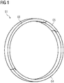
- the sealing ring 01 consists of three ring segments 03, 04, 05, with two ring segments 03 and 04 being designed as identical parts and extending over an angle of slightly more than 170°. Furthermore, there is a closing ring segment 05, which 05 extends over an angular range of approximately 15° - see also 7 .
- the sealing ring 01 is accommodated in a groove on a rotor disk 17 .
- This 17 here has a plurality of blade retaining grooves 18 distributed around the circumference, in each of which rotor blades 19 are fastened with a blade root.
- the closing ring segment 05 is arranged in front of a blade retaining groove 18 and thus in front of the blade root of the moving blade 19 .
- the overlapping area on both sides to the adjacent ring segments 03, 04 is arranged in an area in front of the rotor disk 17 between the blade retaining grooves 18.
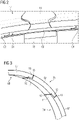
- FIG 3 becomes a section of the sealing ring 1 outlined in the area of the closing ring segment 05.
- the ring segments 03, 04 and 05 each have a ring section 07 which extends in sections in the circumferential direction and has a constant cross section.
- the respective overlapping area is located on both sides at the ends of the ring sections 07, with either a pressing section 11 or a triangular section 13 being arranged at the respective end.
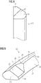
- the sealing ring 01 initially has a contact surface 21 on the side facing away from the rotor disk 17 .
- this 21 extends in the radial direction and is delimited on the side pointing towards the rotor axis by an inner contact edge 23 and on the side pointing radially outwards by an outer contact edge 22.
- sealing elements 09 come into contact with the contact surface 21 .
- the sealing ring 01 has an inclined support surface 24 on the side pointing radially outwards and towards the rotor disk 17 .
- This 24 is inclined at an angle of approximately 40° to the rotor axis.
- the support surface 24 is bounded by a front support edge 25 on the side pointing radially outwards, with this 25 also being located on the side on the sealing ring 01 pointing towards the contact surface 21 .
- the supporting surface 24 is delimited by the rear supporting edge 26 , which is arranged at the end of the supporting surface 24 pointing towards the rotor axis and pointing away from the contact surface 21 .
- the support surface 24 is connected to the contact surface 21 via a flattening 31 .
- the sealing ring 01 has an arcuate section 32. This 32 transitions into a straight section 33 on the side of the sealing ring 01 pointing towards the rotor axis.
- the sealing ring 01 has a sealing ring height in the radial direction, measured from the straight section 33 to the flat area 31 .
- a sealing ring width is determined from the contact surface 21 to the opposite end.
- a width of the contact surface 21 from the inner contact edge 23 to the outer contact edge 22 is greater than 0.9 times the height of the sealing ring.
- a width of the support surface 24 measured in the direction of the rotor axis from the front support edge 25 to the rear support edge 26 corresponds to approximately 0.6 times the width of the sealing ring.
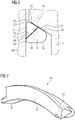
- the overlapping area between two ring segments 03, 04 and 05 is formed in each case by abutting triangular section 13 and pressing section 11—see in particular Figures 4 and 5 .
- the triangular section 13 adjoins a second section end 14 of the corresponding ring section 07 in the circumferential direction—see also in this regard 8 .
- the pressing section 11 adjoins the adjacent ring section 07 at its first section end 12 in the circumferential direction—see here 9 .
- the corresponding gap 15 forms on the one hand between the free end of the triangular section 13 and the adjacent first section end 12 and between the free end of the pressing section 11 and the adjacent second section end 14.
- the triangular section 13 is in contact with the pressing section 11 along a parting surface 27 .
- the separating surface 27 extends here from a lower edge of the separating surface 28 to an upper interface edge 29. As in particular from 4 As can be seen, the lower parting surface edge 28 intersects the contact surface 21 in sections between the first section end 12 and the second section end 14. It is therefore obvious that both the triangular section 13 and the pressing section 11 have the contact surface 21 in sections.
- the separating surface 27 extends inclined to the supporting surface 24 . This leads to the upper parting surface edge 29 intersecting the support surface 24 in sections.
- both the triangular section 13 and the pressing section 11 have the support surface 24 in sections.
- the separating surface 27 is arranged diagonally and in this case has an angle of 45° to the rotor axis and thus 45° to the radial direction.
- the lower parting surface edge 29 is located directly on the rear supporting edge 26 and thus only a minimal strip of the supporting surface 24 remains on the pressing section 11 .
Landscapes
- Engineering & Computer Science (AREA)
- General Engineering & Computer Science (AREA)
- Mechanical Engineering (AREA)
- Turbine Rotor Nozzle Sealing (AREA)
- Sealing Devices (AREA)
- Sealing Using Fluids, Sealing Without Contact, And Removal Of Oil (AREA)
Priority Applications (5)
| Application Number | Priority Date | Filing Date | Title |
|---|---|---|---|
| EP20165112.2A EP3885535B1 (de) | 2020-03-24 | 2020-03-24 | Dichtring für einen rotor und rotor mit einem solchen |
| US17/202,762 US11365639B2 (en) | 2020-03-24 | 2021-03-16 | Sealing washer for a rotor, and rotor with such a washer |
| JP2021042426A JP7214774B2 (ja) | 2020-03-24 | 2021-03-16 | ロータ用のシールリングおよびこのようなシールリングを有するロータ |
| KR1020210035628A KR102539951B1 (ko) | 2020-03-24 | 2021-03-19 | 로터용 밀봉 와셔 및 상기 밀봉 와셔를 구비한 로터 |
| CN202110308668.2A CN113503362B (zh) | 2020-03-24 | 2021-03-23 | 用于转子的密封环和具有这种密封环的转子 |
Applications Claiming Priority (1)
| Application Number | Priority Date | Filing Date | Title |
|---|---|---|---|
| EP20165112.2A EP3885535B1 (de) | 2020-03-24 | 2020-03-24 | Dichtring für einen rotor und rotor mit einem solchen |
Publications (2)
| Publication Number | Publication Date |
|---|---|
| EP3885535A1 EP3885535A1 (de) | 2021-09-29 |
| EP3885535B1 true EP3885535B1 (de) | 2022-09-07 |
Family
ID=69960338
Family Applications (1)
| Application Number | Title | Priority Date | Filing Date |
|---|---|---|---|
| EP20165112.2A Active EP3885535B1 (de) | 2020-03-24 | 2020-03-24 | Dichtring für einen rotor und rotor mit einem solchen |
Country Status (5)
| Country | Link |
|---|---|
| US (1) | US11365639B2 (enExample) |
| EP (1) | EP3885535B1 (enExample) |
| JP (1) | JP7214774B2 (enExample) |
| KR (1) | KR102539951B1 (enExample) |
| CN (1) | CN113503362B (enExample) |
Families Citing this family (1)
| Publication number | Priority date | Publication date | Assignee | Title |
|---|---|---|---|---|
| DE102022205646A1 (de) * | 2022-06-02 | 2023-12-07 | Siemens Energy Global GmbH & Co. KG | Dichtungsring mit überlappenden Dichtungsteilen und Rotoranordnung mit einem solchen |
Family Cites Families (19)
| Publication number | Priority date | Publication date | Assignee | Title |
|---|---|---|---|---|
| US2076164A (en) * | 1934-03-15 | 1937-04-06 | New York Air Brake Co | Piston ring |
| JPH04362370A (ja) * | 1991-06-04 | 1992-12-15 | Riken Corp | 内燃機関用圧縮リング |
| JP2737107B2 (ja) * | 1994-02-24 | 1998-04-08 | 株式会社リケン | 内燃機関用圧縮リング |
| EP0695894B1 (en) | 1994-02-24 | 1998-05-20 | Kabushiki Kaisha Riken | Compression ring for an internal combustion engine |
| JP4064581B2 (ja) * | 1999-10-04 | 2008-03-19 | 三菱重工業株式会社 | 蒸気冷却ガスタービン |
| EP1277995B1 (en) * | 2000-04-28 | 2005-09-07 | NOK Corporation | Seal ring |
| KR100639787B1 (ko) * | 2002-07-26 | 2006-11-01 | 엔오케이 가부시키가이샤 | 밀봉링 |
| JP5029044B2 (ja) * | 2007-02-01 | 2012-09-19 | Nok株式会社 | シールリング |
| GB0718799D0 (en) * | 2007-09-26 | 2007-11-07 | Cross Mfg 1938 Ltd | Sealing rings |
| CH703827A1 (de) * | 2010-09-20 | 2012-03-30 | Alstom Technology Ltd | Gasturbinenanordnung mit einer Ringdichtungsanordnung für einen Ringraum zwischen wenigstens einer stationären Komponente und einer Rotoreinheit. |
| US20120112415A1 (en) * | 2010-11-10 | 2012-05-10 | United Technologies Corporation | Rotating seal ring with targeted split surface orientation |
| FR2982635B1 (fr) * | 2011-11-15 | 2013-11-15 | Snecma | Roue a aubes pour une turbomachine |
| EP2940249A1 (de) * | 2014-04-29 | 2015-11-04 | Siemens Aktiengesellschaft | Radscheibenanordnung und Verfahren zur Montage einer Radscheibenanordnung |
| EP3091191A1 (en) * | 2015-05-08 | 2016-11-09 | Siemens Aktiengesellschaft | Sealing arrangement for a steam turbine |
| CN105443762A (zh) * | 2015-12-14 | 2016-03-30 | 中国燃气涡轮研究院 | 一种双环圆周密封装置 |
| DE102017205794A1 (de) * | 2017-04-05 | 2018-10-11 | Siemens Aktiengesellschaft | Verfahren zur Abdichtung eines Ringspaltes in einer Turbine sowie Turbine |
| CN108547950B (zh) * | 2018-01-01 | 2024-10-11 | 保一集团有限公司 | 三角形环的杆密封 |
| EP3608563B1 (de) * | 2018-08-06 | 2021-03-17 | Siemens Energy Global GmbH & Co. KG | Dichtung zum abdichten eines umfangsspalts zwischen zwei maschinenkomponenten |
| DE102020204514A1 (de) * | 2020-04-07 | 2021-10-07 | Trelleborg Sealing Solutions Germany Gmbh | Dichtungsanordnung mit Dichtungseinheit |
-
2020
- 2020-03-24 EP EP20165112.2A patent/EP3885535B1/de active Active
-
2021
- 2021-03-16 US US17/202,762 patent/US11365639B2/en active Active
- 2021-03-16 JP JP2021042426A patent/JP7214774B2/ja active Active
- 2021-03-19 KR KR1020210035628A patent/KR102539951B1/ko active Active
- 2021-03-23 CN CN202110308668.2A patent/CN113503362B/zh active Active
Also Published As
| Publication number | Publication date |
|---|---|
| CN113503362B (zh) | 2023-12-05 |
| JP7214774B2 (ja) | 2023-01-30 |
| KR102539951B1 (ko) | 2023-06-05 |
| US20210301671A1 (en) | 2021-09-30 |
| US11365639B2 (en) | 2022-06-21 |
| EP3885535A1 (de) | 2021-09-29 |
| CN113503362A (zh) | 2021-10-15 |
| KR20210119316A (ko) | 2021-10-05 |
| JP2021152363A (ja) | 2021-09-30 |
Similar Documents
| Publication | Publication Date | Title |
|---|---|---|
| EP2622244B2 (de) | Zahnradanordnung und verfahren zur herstellung eines bajonettverschlusses | |
| EP2478186B1 (de) | Rotor einer Turbomaschine | |
| WO2007028703A1 (de) | Anordnung zur axialsicherung von laufschaufeln in einem rotor sowie verwendung | |
| EP3999717B1 (de) | Zwischenelement für eine schaufel-rotorscheiben-verbindung bei einem rotor einer strömungsmaschine, rotor für eine strömungsmaschine und strömungsmaschine | |
| EP3428402B1 (de) | Leitschaufelsegment mit gekrümmter entlastungsfuge | |
| EP3333439B1 (de) | Verfahren zum austausch eines gebrauchten lagers, insbesondere zum austausch eines grosslagers, wie das hauptlager einer windkraftanlage sowie lageranordnung | |
| EP2703693A2 (de) | Planetenträger | |
| EP3176384A1 (de) | Innenring, zugehöriger innenringsektor, leitschaufelkranz und strömungsmaschine | |
| DE3407373C2 (de) | Dampfturbinenrotor | |
| EP1081336B1 (de) | Gebauter Leitkranz für eine Gasturbine | |
| EP3885535B1 (de) | Dichtring für einen rotor und rotor mit einem solchen | |
| EP1178232B1 (de) | Flanschmitnehmer für ein Kardangelenk und Gelenkwelle | |
| EP2410131A2 (de) | Rotor einer Turbomaschine | |
| DE69709563T2 (de) | Turbomaschinenschaufeldichtung | |
| EP3025027B1 (de) | Turbinenschaufel sowie gasturbine | |
| EP3375986B1 (de) | Bauteil einer turbomaschine | |
| DE602005000494T2 (de) | Wellen- und Lageranordnung | |
| EP3976932B1 (de) | Laufschaufel mit schaufelfusskontur mit in einem konkaven konturabschnitt vorgesehenem geradenabschnitt | |
| DE19738934A1 (de) | Drehdurchführung für Drehvorrichtungen, insbesondere für Handhabungseinrichtungen und Industrieroboter | |
| EP3170986B1 (de) | Schaufelcluster mit umfangssicherung | |
| EP3724456B1 (de) | Rotor mit fliehkraft-optimierten kontaktflächen | |
| EP3999749B1 (de) | Folienlager | |
| EP3695100B1 (de) | Rotor mit dichtelement und dichtring | |
| EP4511564B1 (de) | Dichtungsring mit überlappenden dichtungsteilen und statoranordnung mit einem solchen | |
| DE3101250A1 (de) | "rotor fuer stroemungsmaschinen, insbesondere axialverdichterrotor fuer gasturbinentriebwerke" |
Legal Events
| Date | Code | Title | Description |
|---|---|---|---|
| PUAI | Public reference made under article 153(3) epc to a published international application that has entered the european phase |
Free format text: ORIGINAL CODE: 0009012 |
|
| STAA | Information on the status of an ep patent application or granted ep patent |
Free format text: STATUS: THE APPLICATION HAS BEEN PUBLISHED |
|
| AK | Designated contracting states |
Kind code of ref document: A1 Designated state(s): AL AT BE BG CH CY CZ DE DK EE ES FI FR GB GR HR HU IE IS IT LI LT LU LV MC MK MT NL NO PL PT RO RS SE SI SK SM TR |
|
| STAA | Information on the status of an ep patent application or granted ep patent |
Free format text: STATUS: REQUEST FOR EXAMINATION WAS MADE |
|
| 17P | Request for examination filed |
Effective date: 20211013 |
|
| RBV | Designated contracting states (corrected) |
Designated state(s): AL AT BE BG CH CY CZ DE DK EE ES FI FR GB GR HR HU IE IS IT LI LT LU LV MC MK MT NL NO PL PT RO RS SE SI SK SM TR |
|
| RAP1 | Party data changed (applicant data changed or rights of an application transferred) |
Owner name: SIEMENS ENERGY GLOBAL GMBH & CO. KG |
|
| GRAP | Despatch of communication of intention to grant a patent |
Free format text: ORIGINAL CODE: EPIDOSNIGR1 |
|
| STAA | Information on the status of an ep patent application or granted ep patent |
Free format text: STATUS: GRANT OF PATENT IS INTENDED |
|
| RIC1 | Information provided on ipc code assigned before grant |
Ipc: F01D 5/30 20060101AFI20220311BHEP |
|
| INTG | Intention to grant announced |
Effective date: 20220404 |
|
| GRAS | Grant fee paid |
Free format text: ORIGINAL CODE: EPIDOSNIGR3 |
|
| GRAA | (expected) grant |
Free format text: ORIGINAL CODE: 0009210 |
|
| STAA | Information on the status of an ep patent application or granted ep patent |
Free format text: STATUS: THE PATENT HAS BEEN GRANTED |
|
| AK | Designated contracting states |
Kind code of ref document: B1 Designated state(s): AL AT BE BG CH CY CZ DE DK EE ES FI FR GB GR HR HU IE IS IT LI LT LU LV MC MK MT NL NO PL PT RO RS SE SI SK SM TR |
|
| REG | Reference to a national code |
Ref country code: GB Ref legal event code: FG4D Free format text: NOT ENGLISH |
|
| REG | Reference to a national code |
Ref country code: CH Ref legal event code: EP Ref country code: AT Ref legal event code: REF Ref document number: 1517200 Country of ref document: AT Kind code of ref document: T Effective date: 20220915 |
|
| REG | Reference to a national code |
Ref country code: DE Ref legal event code: R096 Ref document number: 502020001633 Country of ref document: DE |
|
| REG | Reference to a national code |
Ref country code: IE Ref legal event code: FG4D Free format text: LANGUAGE OF EP DOCUMENT: GERMAN |
|
| REG | Reference to a national code |
Ref country code: LT Ref legal event code: MG9D |
|
| REG | Reference to a national code |
Ref country code: NL Ref legal event code: MP Effective date: 20220907 |
|
| PG25 | Lapsed in a contracting state [announced via postgrant information from national office to epo] |
Ref country code: SE Free format text: LAPSE BECAUSE OF FAILURE TO SUBMIT A TRANSLATION OF THE DESCRIPTION OR TO PAY THE FEE WITHIN THE PRESCRIBED TIME-LIMIT Effective date: 20220907 Ref country code: RS Free format text: LAPSE BECAUSE OF FAILURE TO SUBMIT A TRANSLATION OF THE DESCRIPTION OR TO PAY THE FEE WITHIN THE PRESCRIBED TIME-LIMIT Effective date: 20220907 Ref country code: NO Free format text: LAPSE BECAUSE OF FAILURE TO SUBMIT A TRANSLATION OF THE DESCRIPTION OR TO PAY THE FEE WITHIN THE PRESCRIBED TIME-LIMIT Effective date: 20221207 Ref country code: LV Free format text: LAPSE BECAUSE OF FAILURE TO SUBMIT A TRANSLATION OF THE DESCRIPTION OR TO PAY THE FEE WITHIN THE PRESCRIBED TIME-LIMIT Effective date: 20220907 Ref country code: LT Free format text: LAPSE BECAUSE OF FAILURE TO SUBMIT A TRANSLATION OF THE DESCRIPTION OR TO PAY THE FEE WITHIN THE PRESCRIBED TIME-LIMIT Effective date: 20220907 Ref country code: FI Free format text: LAPSE BECAUSE OF FAILURE TO SUBMIT A TRANSLATION OF THE DESCRIPTION OR TO PAY THE FEE WITHIN THE PRESCRIBED TIME-LIMIT Effective date: 20220907 |
|
| PG25 | Lapsed in a contracting state [announced via postgrant information from national office to epo] |
Ref country code: HR Free format text: LAPSE BECAUSE OF FAILURE TO SUBMIT A TRANSLATION OF THE DESCRIPTION OR TO PAY THE FEE WITHIN THE PRESCRIBED TIME-LIMIT Effective date: 20220907 Ref country code: GR Free format text: LAPSE BECAUSE OF FAILURE TO SUBMIT A TRANSLATION OF THE DESCRIPTION OR TO PAY THE FEE WITHIN THE PRESCRIBED TIME-LIMIT Effective date: 20221208 |
|
| RAP4 | Party data changed (patent owner data changed or rights of a patent transferred) |
Owner name: SIEMENS ENERGY GLOBAL GMBH & CO. KG |
|
| PG25 | Lapsed in a contracting state [announced via postgrant information from national office to epo] |
Ref country code: SM Free format text: LAPSE BECAUSE OF FAILURE TO SUBMIT A TRANSLATION OF THE DESCRIPTION OR TO PAY THE FEE WITHIN THE PRESCRIBED TIME-LIMIT Effective date: 20220907 Ref country code: RO Free format text: LAPSE BECAUSE OF FAILURE TO SUBMIT A TRANSLATION OF THE DESCRIPTION OR TO PAY THE FEE WITHIN THE PRESCRIBED TIME-LIMIT Effective date: 20220907 Ref country code: PT Free format text: LAPSE BECAUSE OF FAILURE TO SUBMIT A TRANSLATION OF THE DESCRIPTION OR TO PAY THE FEE WITHIN THE PRESCRIBED TIME-LIMIT Effective date: 20230109 Ref country code: ES Free format text: LAPSE BECAUSE OF FAILURE TO SUBMIT A TRANSLATION OF THE DESCRIPTION OR TO PAY THE FEE WITHIN THE PRESCRIBED TIME-LIMIT Effective date: 20220907 Ref country code: CZ Free format text: LAPSE BECAUSE OF FAILURE TO SUBMIT A TRANSLATION OF THE DESCRIPTION OR TO PAY THE FEE WITHIN THE PRESCRIBED TIME-LIMIT Effective date: 20220907 |
|
| PG25 | Lapsed in a contracting state [announced via postgrant information from national office to epo] |
Ref country code: SK Free format text: LAPSE BECAUSE OF FAILURE TO SUBMIT A TRANSLATION OF THE DESCRIPTION OR TO PAY THE FEE WITHIN THE PRESCRIBED TIME-LIMIT Effective date: 20220907 Ref country code: PL Free format text: LAPSE BECAUSE OF FAILURE TO SUBMIT A TRANSLATION OF THE DESCRIPTION OR TO PAY THE FEE WITHIN THE PRESCRIBED TIME-LIMIT Effective date: 20220907 Ref country code: IS Free format text: LAPSE BECAUSE OF FAILURE TO SUBMIT A TRANSLATION OF THE DESCRIPTION OR TO PAY THE FEE WITHIN THE PRESCRIBED TIME-LIMIT Effective date: 20230107 Ref country code: EE Free format text: LAPSE BECAUSE OF FAILURE TO SUBMIT A TRANSLATION OF THE DESCRIPTION OR TO PAY THE FEE WITHIN THE PRESCRIBED TIME-LIMIT Effective date: 20220907 |
|
| REG | Reference to a national code |
Ref country code: DE Ref legal event code: R097 Ref document number: 502020001633 Country of ref document: DE |
|
| PG25 | Lapsed in a contracting state [announced via postgrant information from national office to epo] |
Ref country code: NL Free format text: LAPSE BECAUSE OF FAILURE TO SUBMIT A TRANSLATION OF THE DESCRIPTION OR TO PAY THE FEE WITHIN THE PRESCRIBED TIME-LIMIT Effective date: 20220907 Ref country code: AL Free format text: LAPSE BECAUSE OF FAILURE TO SUBMIT A TRANSLATION OF THE DESCRIPTION OR TO PAY THE FEE WITHIN THE PRESCRIBED TIME-LIMIT Effective date: 20220907 |
|
| PLBE | No opposition filed within time limit |
Free format text: ORIGINAL CODE: 0009261 |
|
| STAA | Information on the status of an ep patent application or granted ep patent |
Free format text: STATUS: NO OPPOSITION FILED WITHIN TIME LIMIT |
|
| PG25 | Lapsed in a contracting state [announced via postgrant information from national office to epo] |
Ref country code: DK Free format text: LAPSE BECAUSE OF FAILURE TO SUBMIT A TRANSLATION OF THE DESCRIPTION OR TO PAY THE FEE WITHIN THE PRESCRIBED TIME-LIMIT Effective date: 20220907 |
|
| 26N | No opposition filed |
Effective date: 20230608 |
|
| PG25 | Lapsed in a contracting state [announced via postgrant information from national office to epo] |
Ref country code: SI Free format text: LAPSE BECAUSE OF FAILURE TO SUBMIT A TRANSLATION OF THE DESCRIPTION OR TO PAY THE FEE WITHIN THE PRESCRIBED TIME-LIMIT Effective date: 20220907 |
|
| PG25 | Lapsed in a contracting state [announced via postgrant information from national office to epo] |
Ref country code: MC Free format text: LAPSE BECAUSE OF FAILURE TO SUBMIT A TRANSLATION OF THE DESCRIPTION OR TO PAY THE FEE WITHIN THE PRESCRIBED TIME-LIMIT Effective date: 20220907 |
|
| REG | Reference to a national code |
Ref country code: CH Ref legal event code: PL |
|
| REG | Reference to a national code |
Ref country code: BE Ref legal event code: MM Effective date: 20230331 |
|
| PG25 | Lapsed in a contracting state [announced via postgrant information from national office to epo] |
Ref country code: LU Free format text: LAPSE BECAUSE OF NON-PAYMENT OF DUE FEES Effective date: 20230324 |
|
| REG | Reference to a national code |
Ref country code: IE Ref legal event code: MM4A |
|
| PG25 | Lapsed in a contracting state [announced via postgrant information from national office to epo] |
Ref country code: LI Free format text: LAPSE BECAUSE OF NON-PAYMENT OF DUE FEES Effective date: 20230331 Ref country code: IE Free format text: LAPSE BECAUSE OF NON-PAYMENT OF DUE FEES Effective date: 20230324 Ref country code: CH Free format text: LAPSE BECAUSE OF NON-PAYMENT OF DUE FEES Effective date: 20230331 |
|
| PG25 | Lapsed in a contracting state [announced via postgrant information from national office to epo] |
Ref country code: BE Free format text: LAPSE BECAUSE OF NON-PAYMENT OF DUE FEES Effective date: 20230331 |
|
| PG25 | Lapsed in a contracting state [announced via postgrant information from national office to epo] |
Ref country code: BG Free format text: LAPSE BECAUSE OF FAILURE TO SUBMIT A TRANSLATION OF THE DESCRIPTION OR TO PAY THE FEE WITHIN THE PRESCRIBED TIME-LIMIT Effective date: 20220907 |
|
| GBPC | Gb: european patent ceased through non-payment of renewal fee |
Effective date: 20240324 |
|
| PG25 | Lapsed in a contracting state [announced via postgrant information from national office to epo] |
Ref country code: BG Free format text: LAPSE BECAUSE OF FAILURE TO SUBMIT A TRANSLATION OF THE DESCRIPTION OR TO PAY THE FEE WITHIN THE PRESCRIBED TIME-LIMIT Effective date: 20220907 |
|
| PG25 | Lapsed in a contracting state [announced via postgrant information from national office to epo] |
Ref country code: GB Free format text: LAPSE BECAUSE OF NON-PAYMENT OF DUE FEES Effective date: 20240324 |
|
| PG25 | Lapsed in a contracting state [announced via postgrant information from national office to epo] |
Ref country code: GB Free format text: LAPSE BECAUSE OF NON-PAYMENT OF DUE FEES Effective date: 20240324 |
|
| PGFP | Annual fee paid to national office [announced via postgrant information from national office to epo] |
Ref country code: DE Payment date: 20250327 Year of fee payment: 6 |
|
| PGFP | Annual fee paid to national office [announced via postgrant information from national office to epo] |
Ref country code: AT Payment date: 20250417 Year of fee payment: 5 |
|
| PGFP | Annual fee paid to national office [announced via postgrant information from national office to epo] |
Ref country code: FR Payment date: 20250324 Year of fee payment: 6 |
|
| PGFP | Annual fee paid to national office [announced via postgrant information from national office to epo] |
Ref country code: IT Payment date: 20250321 Year of fee payment: 6 |
|
| PG25 | Lapsed in a contracting state [announced via postgrant information from national office to epo] |
Ref country code: CY Free format text: LAPSE BECAUSE OF FAILURE TO SUBMIT A TRANSLATION OF THE DESCRIPTION OR TO PAY THE FEE WITHIN THE PRESCRIBED TIME-LIMIT; INVALID AB INITIO Effective date: 20200324 |
|
| PG25 | Lapsed in a contracting state [announced via postgrant information from national office to epo] |
Ref country code: HU Free format text: LAPSE BECAUSE OF FAILURE TO SUBMIT A TRANSLATION OF THE DESCRIPTION OR TO PAY THE FEE WITHIN THE PRESCRIBED TIME-LIMIT; INVALID AB INITIO Effective date: 20200324 |
|
| PG25 | Lapsed in a contracting state [announced via postgrant information from national office to epo] |
Ref country code: TR Free format text: LAPSE BECAUSE OF FAILURE TO SUBMIT A TRANSLATION OF THE DESCRIPTION OR TO PAY THE FEE WITHIN THE PRESCRIBED TIME-LIMIT Effective date: 20220907 |