EP3885535B1 - Sealing ring for a rotor and rotor with such a sealing ring - Google Patents
Sealing ring for a rotor and rotor with such a sealing ring Download PDFInfo
- Publication number
- EP3885535B1 EP3885535B1 EP20165112.2A EP20165112A EP3885535B1 EP 3885535 B1 EP3885535 B1 EP 3885535B1 EP 20165112 A EP20165112 A EP 20165112A EP 3885535 B1 EP3885535 B1 EP 3885535B1
- Authority
- EP
- European Patent Office
- Prior art keywords
- section
- edge
- washer
- face
- sealing washer
- Prior art date
- Legal status (The legal status is an assumption and is not a legal conclusion. Google has not performed a legal analysis and makes no representation as to the accuracy of the status listed.)
- Active
Links
- 238000007789 sealing Methods 0.000 title claims description 92
- 238000003825 pressing Methods 0.000 claims description 23
- 238000000926 separation method Methods 0.000 claims description 6
- 125000006413 ring segment Chemical group 0.000 description 35
- 230000015572 biosynthetic process Effects 0.000 description 2
- 238000009434 installation Methods 0.000 description 2
- 230000001419 dependent effect Effects 0.000 description 1
- 238000009826 distribution Methods 0.000 description 1
- 238000004519 manufacturing process Methods 0.000 description 1
- 238000007493 shaping process Methods 0.000 description 1
- 238000003860 storage Methods 0.000 description 1
- 230000007704 transition Effects 0.000 description 1
Images

Classifications
-
- F—MECHANICAL ENGINEERING; LIGHTING; HEATING; WEAPONS; BLASTING
- F01—MACHINES OR ENGINES IN GENERAL; ENGINE PLANTS IN GENERAL; STEAM ENGINES
- F01D—NON-POSITIVE DISPLACEMENT MACHINES OR ENGINES, e.g. STEAM TURBINES
- F01D11/00—Preventing or minimising internal leakage of working-fluid, e.g. between stages
- F01D11/005—Sealing means between non relatively rotating elements
- F01D11/006—Sealing the gap between rotor blades or blades and rotor
-
- F—MECHANICAL ENGINEERING; LIGHTING; HEATING; WEAPONS; BLASTING
- F01—MACHINES OR ENGINES IN GENERAL; ENGINE PLANTS IN GENERAL; STEAM ENGINES
- F01D—NON-POSITIVE DISPLACEMENT MACHINES OR ENGINES, e.g. STEAM TURBINES
- F01D5/00—Blades; Blade-carrying members; Heating, heat-insulating, cooling or antivibration means on the blades or the members
- F01D5/30—Fixing blades to rotors; Blade roots ; Blade spacers
- F01D5/3007—Fixing blades to rotors; Blade roots ; Blade spacers of axial insertion type
-
- F—MECHANICAL ENGINEERING; LIGHTING; HEATING; WEAPONS; BLASTING
- F16—ENGINEERING ELEMENTS AND UNITS; GENERAL MEASURES FOR PRODUCING AND MAINTAINING EFFECTIVE FUNCTIONING OF MACHINES OR INSTALLATIONS; THERMAL INSULATION IN GENERAL
- F16J—PISTONS; CYLINDERS; SEALINGS
- F16J15/00—Sealings
- F16J15/16—Sealings between relatively-moving surfaces
- F16J15/32—Sealings between relatively-moving surfaces with elastic sealings, e.g. O-rings
- F16J15/3268—Mounting of sealing rings
-
- F—MECHANICAL ENGINEERING; LIGHTING; HEATING; WEAPONS; BLASTING
- F01—MACHINES OR ENGINES IN GENERAL; ENGINE PLANTS IN GENERAL; STEAM ENGINES
- F01D—NON-POSITIVE DISPLACEMENT MACHINES OR ENGINES, e.g. STEAM TURBINES
- F01D11/00—Preventing or minimising internal leakage of working-fluid, e.g. between stages
- F01D11/003—Preventing or minimising internal leakage of working-fluid, e.g. between stages by packing rings; Mechanical seals
-
- F—MECHANICAL ENGINEERING; LIGHTING; HEATING; WEAPONS; BLASTING
- F01—MACHINES OR ENGINES IN GENERAL; ENGINE PLANTS IN GENERAL; STEAM ENGINES
- F01D—NON-POSITIVE DISPLACEMENT MACHINES OR ENGINES, e.g. STEAM TURBINES
- F01D5/00—Blades; Blade-carrying members; Heating, heat-insulating, cooling or antivibration means on the blades or the members
- F01D5/02—Blade-carrying members, e.g. rotors
-
- F—MECHANICAL ENGINEERING; LIGHTING; HEATING; WEAPONS; BLASTING
- F16—ENGINEERING ELEMENTS AND UNITS; GENERAL MEASURES FOR PRODUCING AND MAINTAINING EFFECTIVE FUNCTIONING OF MACHINES OR INSTALLATIONS; THERMAL INSULATION IN GENERAL
- F16J—PISTONS; CYLINDERS; SEALINGS
- F16J15/00—Sealings
- F16J15/16—Sealings between relatively-moving surfaces
- F16J15/32—Sealings between relatively-moving surfaces with elastic sealings, e.g. O-rings
- F16J15/3284—Sealings between relatively-moving surfaces with elastic sealings, e.g. O-rings characterised by their structure; Selection of materials
-
- F—MECHANICAL ENGINEERING; LIGHTING; HEATING; WEAPONS; BLASTING
- F01—MACHINES OR ENGINES IN GENERAL; ENGINE PLANTS IN GENERAL; STEAM ENGINES
- F01D—NON-POSITIVE DISPLACEMENT MACHINES OR ENGINES, e.g. STEAM TURBINES
- F01D5/00—Blades; Blade-carrying members; Heating, heat-insulating, cooling or antivibration means on the blades or the members
- F01D5/30—Fixing blades to rotors; Blade roots ; Blade spacers
- F01D5/3007—Fixing blades to rotors; Blade roots ; Blade spacers of axial insertion type
- F01D5/3015—Fixing blades to rotors; Blade roots ; Blade spacers of axial insertion type with side plates
-
- F—MECHANICAL ENGINEERING; LIGHTING; HEATING; WEAPONS; BLASTING
- F05—INDEXING SCHEMES RELATING TO ENGINES OR PUMPS IN VARIOUS SUBCLASSES OF CLASSES F01-F04
- F05D—INDEXING SCHEME FOR ASPECTS RELATING TO NON-POSITIVE-DISPLACEMENT MACHINES OR ENGINES, GAS-TURBINES OR JET-PROPULSION PLANTS
- F05D2220/00—Application
- F05D2220/30—Application in turbines
- F05D2220/32—Application in turbines in gas turbines
-
- F—MECHANICAL ENGINEERING; LIGHTING; HEATING; WEAPONS; BLASTING
- F05—INDEXING SCHEMES RELATING TO ENGINES OR PUMPS IN VARIOUS SUBCLASSES OF CLASSES F01-F04
- F05D—INDEXING SCHEME FOR ASPECTS RELATING TO NON-POSITIVE-DISPLACEMENT MACHINES OR ENGINES, GAS-TURBINES OR JET-PROPULSION PLANTS
- F05D2240/00—Components
- F05D2240/20—Rotors
- F05D2240/30—Characteristics of rotor blades, i.e. of any element transforming dynamic fluid energy to or from rotational energy and being attached to a rotor
-
- F—MECHANICAL ENGINEERING; LIGHTING; HEATING; WEAPONS; BLASTING
- F05—INDEXING SCHEMES RELATING TO ENGINES OR PUMPS IN VARIOUS SUBCLASSES OF CLASSES F01-F04
- F05D—INDEXING SCHEME FOR ASPECTS RELATING TO NON-POSITIVE-DISPLACEMENT MACHINES OR ENGINES, GAS-TURBINES OR JET-PROPULSION PLANTS
- F05D2240/00—Components
- F05D2240/55—Seals
-
- F—MECHANICAL ENGINEERING; LIGHTING; HEATING; WEAPONS; BLASTING
- F05—INDEXING SCHEMES RELATING TO ENGINES OR PUMPS IN VARIOUS SUBCLASSES OF CLASSES F01-F04
- F05D—INDEXING SCHEME FOR ASPECTS RELATING TO NON-POSITIVE-DISPLACEMENT MACHINES OR ENGINES, GAS-TURBINES OR JET-PROPULSION PLANTS
- F05D2250/00—Geometry
- F05D2250/10—Two-dimensional
- F05D2250/11—Two-dimensional triangular
-
- F—MECHANICAL ENGINEERING; LIGHTING; HEATING; WEAPONS; BLASTING
- F05—INDEXING SCHEMES RELATING TO ENGINES OR PUMPS IN VARIOUS SUBCLASSES OF CLASSES F01-F04
- F05D—INDEXING SCHEME FOR ASPECTS RELATING TO NON-POSITIVE-DISPLACEMENT MACHINES OR ENGINES, GAS-TURBINES OR JET-PROPULSION PLANTS
- F05D2250/00—Geometry
- F05D2250/10—Two-dimensional
- F05D2250/13—Two-dimensional trapezoidal
-
- F—MECHANICAL ENGINEERING; LIGHTING; HEATING; WEAPONS; BLASTING
- F05—INDEXING SCHEMES RELATING TO ENGINES OR PUMPS IN VARIOUS SUBCLASSES OF CLASSES F01-F04
- F05D—INDEXING SCHEME FOR ASPECTS RELATING TO NON-POSITIVE-DISPLACEMENT MACHINES OR ENGINES, GAS-TURBINES OR JET-PROPULSION PLANTS
- F05D2250/00—Geometry
- F05D2250/10—Two-dimensional
- F05D2250/18—Two-dimensional patterned
- F05D2250/182—Two-dimensional patterned crenellated, notched
-
- F—MECHANICAL ENGINEERING; LIGHTING; HEATING; WEAPONS; BLASTING
- F05—INDEXING SCHEMES RELATING TO ENGINES OR PUMPS IN VARIOUS SUBCLASSES OF CLASSES F01-F04
- F05D—INDEXING SCHEME FOR ASPECTS RELATING TO NON-POSITIVE-DISPLACEMENT MACHINES OR ENGINES, GAS-TURBINES OR JET-PROPULSION PLANTS
- F05D2260/00—Function
- F05D2260/30—Retaining components in desired mutual position
- F05D2260/36—Retaining components in desired mutual position by a form fit connection, e.g. by interlocking
Definitions
- the invention relates to a two-part or multi-part sealing ring for use in a rotor, in particular in a gas turbine, with the ends of the sealing ring overlapping in order to reduce leakage through the gap that is formed. It is provided that the sealing ring causes a seal against other rotor components by means of centrifugal force. In the type presented here, the cross section of the sealing ring is very small compared to its diameter.
- a sealing ring is known from the prior art, which has two sealing surfaces which are arranged at an angle to one another and which cause a gap to be sealed when the rotor rotates by means of centrifugal force.
- one of the two sealing surfaces is in contact with a rotor component on one side of the gap and the other sealing surface is in contact with another rotor component on the other side of the gap.
- the document EP 2 453 150 A1 discloses a sealing ring comprising the technical features of the preamble of independent claim 1.
- the sealing ring Due to the multi-part design of the sealing ring, the ends of the individual sealing ring segments overlap so that no new gap remains open between the sealing ring segments. Due to the relatively small cross-section, the sealing ring is basically divided in half on the middle radius in the overlapping sections, so that both sections lying on top of one another have sufficient rigidity.
- a disadvantage of the known embodiment is that there remains a gap, albeit a very small one, that is not completely sealed at the overlap.
- the known embodiment means that one of the two sections only partially encompasses one of the two sealing surfaces, but has no seal on the other sealing surface.
- the object of the present invention is therefore to further improve the sealing by means of a sealing ring.
- the generic sealing ring is initially used in a rotor to seal a circumferential gap between different rotor components. What type of rotor is involved is initially irrelevant, with use being particularly appropriate in a gas turbine.
- the sealing ring or the rotor defines a rotor axis.
- the sealing ring has a contact surface which extends approximately radially and in the circumferential direction. This is considered to be the case when the angle between the contact surface and a radial direction is a maximum of 15°.
- the contact surface is delimited on the side pointing towards the rotor axis by an inner contact edge and on the side pointing radially outwards by an outer contact edge.
- the sealing ring has a supporting surface aligned at an angle to the rotor axis. It is provided here that an angle between the support surface and the rotor axis is at least 15°, but at most 45°. Viewed in the direction of the rotor axis, the support surface is delimited on one side by a front support edge and on the opposite side by a rear support edge. In this case, the front support edge is on the side facing the contact surface, while the rear support edge is on the side facing away from the contact surface on the sealing ring.
- the sealing ring comprises at least one ring section with a substantially constant cross section. Furthermore, the sealing ring has a pressing section and a triangular section.
- the pressing section is integrally connected to a first section end of the ring section in the circumferential direction.
- the triangular section is integrally connected at a second section end to a ring section, which may be the same ring section as before or a different ring section. This creates a separation point. It is provided that at the at least one separation point the pressing section overlaps the triangular section in the circumferential direction and thus forms an overlapping area.
- a gap remains between the free end of the pressing section and the second end of the section and also between the free end of the triangular section and the first end of the section.
- the gaps are necessary here in order to allow tolerance compensation and different thermal expansions of the rotor components and the sealing ring.
- the gaps can be structurally provided with the same dimensions.
- the separation between the triangular section and the pressing section forms a separating surface. Viewed in the axial direction, the separating surface is delimited on the one hand by a lower separating surface edge and opposite by an upper separating surface edge.
- the lower edge of the parting surface is generically located between the center of the contact surface and the inner contact edge of the contact surface.
- both the triangular section and the pressing section have the contact surface in sections. If it is ensured that both the triangular section and the pressing section rest reliably on the adjacent rotor component with the contact surface, the tightness at this point is essentially guaranteed.
- the separating surface is now aligned in the opposite direction to the support surface and an unequal distribution between the triangular section and the support section is accepted.
- the cross-sectional area of the triangular section corresponds to only up to 0.3 times the cross-sectional area of the annular section. Consequently, the cross section of the pressing section is at least twice the cross-sectional area of the triangular section. This leads to the possibility of locating the top parting edge in an area between the center of the support surface and the rear support edge.
- the embodiment according to the invention makes it possible to also provide the triangular section and the pressing section as overlapping sections of the sealing ring with at least a portion of the support surface, so that a seal can also be essentially guaranteed in this area. A leakage in the area of the overlap can thus be further reduced compared to the embodiment in the prior art.
- Sealing by means of the sealing ring is advantageously ensured if the corresponding sealing surfaces have a sufficient width.
- the sealing surface is as wide as possible.
- the contact surface has a contact height from the lower contact edge to the upper contact edge, measured in the radial direction, of at least 0.5 times the height of the sealing ring, also measured as a dimension in the radial direction. It is the same
- the support surface has a support width from the rear support edge to the front support edge, measured in the axial direction, of at least 0.5 times the width of the sealing ring, also measured in the axial direction.
- the lower edge of the parting surface is arranged in the vicinity of the inner bearing edge, the distance from the center of the bearing surface being greater than the distance from the inner bearing edge.
- the upper edge of the parting surface is arranged in the vicinity of the rear supporting edge.
- the distance between the upper edge of the parting surface and the rear supporting edge should be selected to be less than the distance between the upper edge of the parting surface and the center of the supporting surface.
- the separating surface is oriented inclined in the opposite direction to the supporting surface.
- an angle between the separating surface and the radial direction is between 35° and 55°. From this it follows that the advantageous angle between the parting surface and the rotor axis is also between 35° and 55°.
- the angle between the separating surface and the radial direction or between the separating surface and the rotor axis is between 40° and 50° and is arranged diagonally—in the opposite direction to the support surface.
- the sealing ring is advantageously formed by at least two ring segments.
- each of the ring segments has a ring section, at whose two opposite ends in the circumferential direction either a pressing section or a triangular section is connected. Consequently, there are two separation points with two ring segments.
- a closing ring segment is present. It is provided that a triangular section is present on both sides of the closing ring segment. This simplifies a final assembly of the closing ring segment to form the sealing ring.
- a closing ring segment is advantageously used, which extends over a maximum circumference of 20°.
- This design has the particular advantage that only a small piece of the sealing ring in the form of the closing ring segment needs to be removed in order to create a free space, for example for the installation of a moving blade. It is initially irrelevant whether this is combined with the arrangement of the triangular sections at its opposite ends.
- the manufacture and storage of the ring segments is simplified if at least two, particularly preferably all of the existing ring segments are formed from identical parts.
- the gap to be sealed between the adjacent rotor components is small compared to the width of the sealing ring.
- the distance between the support surface and thus the outer bearing edge to the bearing surface and thus to the outer bearing edge is advantageously not selected to be greater than 0.2 times the width of the sealing ring measured in the axial direction for sealing purposes.
- a seal can be optimally close to the gap.
- the sealing ring In order to avoid a sharp-edged groove in a rotor disk for arranging the sealing ring while taking into account the smallest possible installation space for the sealing ring and thereby ensuring the necessary stability of the sealing ring, it is advantageous if this is rounded opposite to the contact surface.
- the sealing ring viewed in cross section, has an arcuate section pointing radially inwards in relation to the contact surface adjoining the support surface. This enables an analogous shaping in the rotor disk and thus avoids the formation of stress peaks in the circumferential groove required for this purpose (continuous or multi-part in the circumferential direction).
- a straight section is arranged opposite the support surface on the side pointing towards the rotor axis, which connects the arcuate section directly or indirectly to the contact surface or the inner contact edge.
- the rotor comprises at least one rotor disk, on which a plurality of moving blades are arranged distributed around the circumference.
- the rotor disk has a corresponding number of blade retaining grooves which extend through the rotor disk and in which a blade root of the respective moving blades is arranged.
- the rotor disk, together with the rotor blades or their blade roots, has an end face in front of which a plurality of sealing elements are distributed around the circumference.
- the sealing elements preferably cover the blade roots and, to that extent, the blade retaining grooves.
- the sealing ring used in this case advantageously has a closing ring segment which enables the assembly or disassembly of rotor blades without complete removal of the entire sealing ring.
- the closing ring segment extends over a length that is greater than the width of a blade root.
- the closing ring segment is not longer than necessary in the circumferential direction.
- the overlapping angular range of the closing ring segment is selected to be smaller than corresponds to twice the pitch of the blade retaining grooves. With 72 blade retaining grooves, for example, the closing ring segment extends over a maximum of 10°.
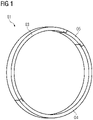
- the sealing ring 01 consists of three ring segments 03, 04, 05, with two ring segments 03 and 04 being designed as identical parts and extending over an angle of slightly more than 170°. Furthermore, there is a closing ring segment 05, which 05 extends over an angular range of approximately 15° - see also 7 .
- the sealing ring 01 is accommodated in a groove on a rotor disk 17 .
- This 17 here has a plurality of blade retaining grooves 18 distributed around the circumference, in each of which rotor blades 19 are fastened with a blade root.
- the closing ring segment 05 is arranged in front of a blade retaining groove 18 and thus in front of the blade root of the moving blade 19 .
- the overlapping area on both sides to the adjacent ring segments 03, 04 is arranged in an area in front of the rotor disk 17 between the blade retaining grooves 18.
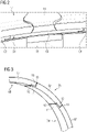
- FIG 3 becomes a section of the sealing ring 1 outlined in the area of the closing ring segment 05.
- the ring segments 03, 04 and 05 each have a ring section 07 which extends in sections in the circumferential direction and has a constant cross section.
- the respective overlapping area is located on both sides at the ends of the ring sections 07, with either a pressing section 11 or a triangular section 13 being arranged at the respective end.
- the sealing ring 01 initially has a contact surface 21 on the side facing away from the rotor disk 17 .
- this 21 extends in the radial direction and is delimited on the side pointing towards the rotor axis by an inner contact edge 23 and on the side pointing radially outwards by an outer contact edge 22.
- sealing elements 09 come into contact with the contact surface 21 .
- the sealing ring 01 has an inclined support surface 24 on the side pointing radially outwards and towards the rotor disk 17 .
- This 24 is inclined at an angle of approximately 40° to the rotor axis.
- the support surface 24 is bounded by a front support edge 25 on the side pointing radially outwards, with this 25 also being located on the side on the sealing ring 01 pointing towards the contact surface 21 .
- the supporting surface 24 is delimited by the rear supporting edge 26 , which is arranged at the end of the supporting surface 24 pointing towards the rotor axis and pointing away from the contact surface 21 .
- the support surface 24 is connected to the contact surface 21 via a flattening 31 .
- the sealing ring 01 has an arcuate section 32. This 32 transitions into a straight section 33 on the side of the sealing ring 01 pointing towards the rotor axis.
- the sealing ring 01 has a sealing ring height in the radial direction, measured from the straight section 33 to the flat area 31 .
- a sealing ring width is determined from the contact surface 21 to the opposite end.
- a width of the contact surface 21 from the inner contact edge 23 to the outer contact edge 22 is greater than 0.9 times the height of the sealing ring.
- a width of the support surface 24 measured in the direction of the rotor axis from the front support edge 25 to the rear support edge 26 corresponds to approximately 0.6 times the width of the sealing ring.
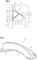
- the overlapping area between two ring segments 03, 04 and 05 is formed in each case by abutting triangular section 13 and pressing section 11—see in particular Figures 4 and 5 .
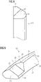
- the triangular section 13 adjoins a second section end 14 of the corresponding ring section 07 in the circumferential direction—see also in this regard 8 .
- the pressing section 11 adjoins the adjacent ring section 07 at its first section end 12 in the circumferential direction—see here 9 .
- the corresponding gap 15 forms on the one hand between the free end of the triangular section 13 and the adjacent first section end 12 and between the free end of the pressing section 11 and the adjacent second section end 14.
- the triangular section 13 is in contact with the pressing section 11 along a parting surface 27 .
- the separating surface 27 extends here from a lower edge of the separating surface 28 to an upper interface edge 29. As in particular from 4 As can be seen, the lower parting surface edge 28 intersects the contact surface 21 in sections between the first section end 12 and the second section end 14. It is therefore obvious that both the triangular section 13 and the pressing section 11 have the contact surface 21 in sections.
- the separating surface 27 extends inclined to the supporting surface 24 . This leads to the upper parting surface edge 29 intersecting the support surface 24 in sections.
- both the triangular section 13 and the pressing section 11 have the support surface 24 in sections.
- the separating surface 27 is arranged diagonally and in this case has an angle of 45° to the rotor axis and thus 45° to the radial direction.
- the lower parting surface edge 29 is located directly on the rear supporting edge 26 and thus only a minimal strip of the supporting surface 24 remains on the pressing section 11 .
Description
Die Erfindung betrifft einen zwei- oder mehrteiligen Dichtring zur Verwendung bei einem Rotor insbesondere bei einer Gasturbine, wobei sich die Enden des Dichtringes überlappen, um somit eine Leckage durch den sich bildenden Spalt zu reduzieren. Dabei ist vorgesehen, dass der Dichtring mittels der Fliehkraft eine Abdichtung gegenüber weiteren Rotorbauteilen bewirkt. Bei der hier vorliegenden Art ist der Querschnitt des Dichtringes sehr klein gegenüber dessen Durchmesser.The invention relates to a two-part or multi-part sealing ring for use in a rotor, in particular in a gas turbine, with the ends of the sealing ring overlapping in order to reduce leakage through the gap that is formed. It is provided that the sealing ring causes a seal against other rotor components by means of centrifugal force. In the type presented here, the cross section of the sealing ring is very small compared to its diameter.
Aus dem Stand der Technik ist ein Dichtring bekannt, welcher zwei in einem Winkel zueinander angeordnete Dichtflächen aufweist, welche bei Rotation des Rotors mittels der Fliehkraft eine Abdichtung eines Spaltes bewirken. Hierbei liegt eine der beiden Dichtflächen an einem Rotorbauteil auf einer Seite des Spaltes und die andere Dichtfläche an einem anderen Rotorbauteil auf der anderen Seite des Spaltes an. Das Dokument
Aufgrund der mehrteiligen Ausführung des Dichtringes überlappen sich die Enden der einzelnen Dichtringsegmente, so dass kein erneuter Spalt zwischen den Dichtringsegmenten offenbleibt. Aufgrund des relativ kleinen Querschnitts ist grundsätzlich bei den sich überlappenden Abschnitten eine hälftige Teilung des Dichtringes auf mittlerem Radius vorhanden, so dass beide übereinanderliegende Abschnitte eine hinreichende Steifigkeit aufweisen.Due to the multi-part design of the sealing ring, the ends of the individual sealing ring segments overlap so that no new gap remains open between the sealing ring segments. Due to the relatively small cross-section, the sealing ring is basically divided in half on the middle radius in the overlapping sections, so that both sections lying on top of one another have sufficient rigidity.
Nachteilig bei bekannter Ausführungsform ist es jedoch, dass eine - wenn auch sehr kleine - nicht vollständig abgedichtete Lücke bei der Überlappung verbleibt. Insbesondere führt die bekannter Ausführungsform dazu, dass einer der beiden Abschnitte nur absatzweise eine der beiden Dichtflächen umfasst, jedoch keine Abdichtung an der anderen Dichtfläche aufweist.A disadvantage of the known embodiment, however, is that there remains a gap, albeit a very small one, that is not completely sealed at the overlap. In particular, the known embodiment means that one of the two sections only partially encompasses one of the two sealing surfaces, but has no seal on the other sealing surface.
Aufgabe der vorliegenden Erfindung ist daher, die Abdichtung mittels eines Dichtringes weiter zu verbessern.The object of the present invention is therefore to further improve the sealing by means of a sealing ring.
Die gestellte Aufgabe wird durch eine erfindungsgemäße Ausführungsform nach der Lehre des Anspruchs 1 gelöst. Ein erfindungsgemäßer Rotor mit entsprechendem Dichtring ist im Anspruch 11 angegeben. Vorteilhafte Ausführungsformen sind Gegenstand der Unteransprüche.The stated object is achieved by an embodiment according to the invention according to the teaching of claim 1. A rotor according to the invention with a corresponding sealing ring is specified in
Der gattungsgemäße Dichtring dient zunächst einmal zur Verwendung bei einem Rotor zur Abdichtung eines umlaufenden Spaltes zwischen verschiedenen Rotorbauteilen. Um welche Art von Rotor es sich hierbei handelt ist zunächst unerheblich, wobei sich die Verwendung insbesondere bei einer Gasturbine anbietet. Dabei definiert der Dichtring bzw. der Rotor eine Rotorachse.The generic sealing ring is initially used in a rotor to seal a circumferential gap between different rotor components. What type of rotor is involved is initially irrelevant, with use being particularly appropriate in a gas turbine. The sealing ring or the rotor defines a rotor axis.
Hierbei weist der Dichtring eine sich ungefähr radial und in Umfangsrichtung erstreckende Anlagefläche auf. Dies wird als gegeben angesehen, wenn der Winkel zwischen der Anlagefläche und einer radialen Richtung maximal 15° beträgt. Dabei wird die Anlagefläche auf der zur Rotorachse weisenden Seite durch einen inneren Anlagerand und auf der radial nach außen weisenden Seite von einem äußeren Anlagerand begrenzt.In this case, the sealing ring has a contact surface which extends approximately radially and in the circumferential direction. This is considered to be the case when the angle between the contact surface and a radial direction is a maximum of 15°. The contact surface is delimited on the side pointing towards the rotor axis by an inner contact edge and on the side pointing radially outwards by an outer contact edge.
Weiterhin weist der Dichtring eine sich geneigt zur Rotorachse ausgerichtete Stützfläche auf. Hierbei ist vorgesehen, dass ein Winkel zwischen der Stützfläche und der Rotorachse mindestens 15°, jedoch maximal 45° beträgt. Dabei wird die Stützfläche in Richtung der Rotorachse betrachtet auf einer Seite von einem vorderen Stützrand und auf gegenüberliegender Seite von einem hinteren Stützrand begrenzt. Hierbei befindet sich der vordere Stützrand auf der zur Anlagefläche weisenden Seite, während demgegenüber sich der hintere Stützrand auf der von der Anlagefläche wegweisenden Seite am Dichtring befindet.Furthermore, the sealing ring has a supporting surface aligned at an angle to the rotor axis. It is provided here that an angle between the support surface and the rotor axis is at least 15°, but at most 45°. Viewed in the direction of the rotor axis, the support surface is delimited on one side by a front support edge and on the opposite side by a rear support edge. In this case, the front support edge is on the side facing the contact surface, while the rear support edge is on the side facing away from the contact surface on the sealing ring.
In Umfangsrichtung umfasst der Dichtring zumindest einen Ringabschnitt mit im Wesentlichen konstantem Querschnitt. Weiterhin weist der Dichtring einen Anpressabschnitt sowie einen Dreiecksabschnitt auf. Dabei schließt sich der Anpressabschnitt einstückig an einem ersten Abschnittsende des Ringabschnitt in Umfangsrichtung an. Demgegenüber ist der Dreiecksabschnitt an einem zweiten Abschnittsende einstückig mit einem Ringabschnitt verbunden, wobei es sich um den gleichen Ringabschnitt wie zuvor oder um einen anderen Ringabschnitt handeln kann. Somit entsteht eine Trennstelle. Dabei ist vorgesehen, dass an der zumindest einen Trennstelle der Anpressabschnitt den Dreiecksabschnitt in Umfangsrichtung überlappt und somit einen Überlappungsbereich bildet.In the circumferential direction, the sealing ring comprises at least one ring section with a substantially constant cross section. Furthermore, the sealing ring has a pressing section and a triangular section. The pressing section is integrally connected to a first section end of the ring section in the circumferential direction. In contrast, the triangular section is integrally connected at a second section end to a ring section, which may be the same ring section as before or a different ring section. This creates a separation point. It is provided that at the at least one separation point the pressing section overlaps the triangular section in the circumferential direction and thus forms an overlapping area.
Dabei verbleibt ein Spalt zwischen dem zwischen dem freien Ende des Anpressabschnitts und dem zweiten Abschnittsende sowie weiterhin zwischen dem freien Ende des Dreiecksabschnitts und dem ersten Abschnittsende. Die Spalte sind hierbei erforderlich, um einen Toleranzausgleich sowie unterschiedliche thermische Dehnungen der Rotorbauteile und des Dichtringes zuzulassen. Dabei können die Spalte konstruktiv mit gleichen Abmessungen vorgesehen sein.A gap remains between the free end of the pressing section and the second end of the section and also between the free end of the triangular section and the first end of the section. The gaps are necessary here in order to allow tolerance compensation and different thermal expansions of the rotor components and the sealing ring. The gaps can be structurally provided with the same dimensions.
Die Trennung zwischen dem Dreiecksabschnitt und dem Anpressabschnitt bildet hierbei eine Trennfläche. Die Trennfläche wird hierbei begrenzt in axialer Richtung betrachtet zum einen durch einen unteren Trennflächenrand und gegenüberliegend von einem oberen Trennflächenrand. Dabei befindet sich gattungsgemäße der untere Trennflächenrand zwischen der Mitte der Anlagefläche und dem inneren Anlagerand der Anlagefläche. Entsprechend weist sowohl der Dreiecksabschnitt als auch der Anpressabschnitt abschnittsweise die Anlagefläche auf. Sofern sichergestellt ist, dass sowohl der Dreiecksabschnitt als auch der Anpressabschnitt zuverlässig am benachbarten Rotorbauteil mit der Anlagefläche anliegen, ist die Dichtigkeit an dieser Stelle im Wesentlichen gewährleistet.The separation between the triangular section and the pressing section forms a separating surface. Viewed in the axial direction, the separating surface is delimited on the one hand by a lower separating surface edge and opposite by an upper separating surface edge. The lower edge of the parting surface is generically located between the center of the contact surface and the inner contact edge of the contact surface. Correspondingly, both the triangular section and the pressing section have the contact surface in sections. If it is ensured that both the triangular section and the pressing section rest reliably on the adjacent rotor component with the contact surface, the tightness at this point is essentially guaranteed.
Aufgrund der Ausrichtung der Stützfläche in Annäherung an eine Zylinderfläche ist es mit der üblichen hälftigen Teilung zwischen den beiden überlappenden Abschnitten im Stand der Technik mit einer Trennfläche, welche im Wesentlichen sich als Abschnitt einer Zylinderfläche darstellt, ausgeschlossen, dass der zur Rotorachse weisende Abschnitt einen Teil der Stützfläche aufweist.Due to the orientation of the support surface in approximation to a cylindrical surface, with the usual half division between the two overlapping sections in the prior art with a dividing surface, which is essentially a section of a cylindrical surface, it is impossible for the section pointing to the rotor axis to have a part the support surface has.
Demgegenüber ist erfindungsgemäß vorgesehen, dass die Trennfläche nunmehr entgegengesetzt zur Stützfläche ausgerichtet wird und dabei eine ungleiche Verteilung zwischen Dreiecksabschnitt und Stützabschnitt hingenommen wird. Dabei ist vorgesehen, dass die Querschnittsfläche des Dreiecksabschnitt lediglich bis zu dem 0,3-Fachen der Querschnittsfläche des Ringabschnitts entspricht. Folglich beträgt der Querschnitt des Anpressabschnitt zumindest dem doppelten Querschnittsfläche des Dreiecksabschnitts. Dies führt zu Möglichkeit den oberen Trennflächenrand in einem Bereich zwischen der Mitte der Stützfläche und dem hinteren Stützrand anzuordnen.In contrast, it is provided according to the invention that the separating surface is now aligned in the opposite direction to the support surface and an unequal distribution between the triangular section and the support section is accepted. It is provided that the cross-sectional area of the triangular section corresponds to only up to 0.3 times the cross-sectional area of the annular section. Consequently, the cross section of the pressing section is at least twice the cross-sectional area of the triangular section. This leads to the possibility of locating the top parting edge in an area between the center of the support surface and the rear support edge.
Durch die erfindungsgemäße Ausführungsform wird es ermöglicht, den Dreiecksabschnitt sowie den Anpressabschnitt als sich überlappende Abschnitte des Dichtringes gleichfalls mit zumindest ansatzweise einem Abschnitt der Stützfläche zu versehen, sodass auch in diesem Bereich eine Abdichtung im Wesentlichen gewährleistet werden kann. Somit kann eine Leckage im Bereich der Überlappung gegenüber der Ausführung im Stand der Technik weiter reduziert werden.The embodiment according to the invention makes it possible to also provide the triangular section and the pressing section as overlapping sections of the sealing ring with at least a portion of the support surface, so that a seal can also be essentially guaranteed in this area. A leakage in the area of the overlap can thus be further reduced compared to the embodiment in the prior art.
Die Abdichtung mittels des Dichtringes wird vorteilhaft gewährleistet, wenn die entsprechenden Dichtflächen eine hinreichende Breite aufweisen. (Im Allgemeinen gilt, dass es vorteilhaft ist, wenn die Dichtfläche möglichst breit ausgeführt wird.) Hierzu ist es vorteilhaft, wenn die Anlagefläche eine Anlagehöhe vom unteren Anlagerand bis zum oberen Anlagerand, gemessen in radialer Richtung, von zumindest dem 0,5-Fachen der Höhe des Dichtringes, gleichfalls als Abmessung in radialer Richtung gemessen, aufweist. Ebenso ist es vorteilhaft, wenn die Stützfläche eine Stützbreite vom hinteren Stützrand bis zum vorderen Stützrand, gemessen in axialer Richtung, von zumindest dem 0,5-Fachen der Breite des Dichtringes, gleichfalls in axialer Richtung gemessen, aufweist.Sealing by means of the sealing ring is advantageously ensured if the corresponding sealing surfaces have a sufficient width. (In general, it is advantageous if the sealing surface is as wide as possible.) For this purpose, it is advantageous if the contact surface has a contact height from the lower contact edge to the upper contact edge, measured in the radial direction, of at least 0.5 times the height of the sealing ring, also measured as a dimension in the radial direction. It is the same It is advantageous if the support surface has a support width from the rear support edge to the front support edge, measured in the axial direction, of at least 0.5 times the width of the sealing ring, also measured in the axial direction.
Zur Gewährleistung eines vorteilhaften Querschnitts des Dreiecksabschnitts ist es vorteilhaft, wenn der untere Trennflächenrand in der Nähe des inneren Anlagerandes angeordnet ist, wobei der Abstand zur Mitte der Anlagefläche größer ist als der Abstand zum inneren Anlagerand. Analog ist es vorteilhaft, wenn der obere Trennflächenrand in der Nähe des hinteren Stützrandes angeordnet wird. Hierzu ist der Abstand des oberen Trennflächenrandes zum hinteren Stützrand geringer zu wählen als der Abstand des oberen Trennflächenrandes zur Mitte der Stützfläche.In order to ensure an advantageous cross section of the triangular section, it is advantageous if the lower edge of the parting surface is arranged in the vicinity of the inner bearing edge, the distance from the center of the bearing surface being greater than the distance from the inner bearing edge. Similarly, it is advantageous if the upper edge of the parting surface is arranged in the vicinity of the rear supporting edge. For this purpose, the distance between the upper edge of the parting surface and the rear supporting edge should be selected to be less than the distance between the upper edge of the parting surface and the center of the supporting surface.
Weiterhin ist es zur erfindungsgemäßen Trennung zwischen dem Dreiecksabschnitt und dem Anpressabschnitt vorteilhaft, wenn die Trennfläche entgegengesetzt zu Stützfläche geneigt ausgerichtet ist. Hierzu ist es vorteilhaft, wenn ein Winkel zwischen der Trennfläche und der radialen Richtung zwischen 35° und 55° beträgt. Daraus folgt naheliegend, dass der vorteilhafte Winkel zwischen der Trennfläche und der Rotorachse gleichfalls zwischen 35° und 55° beträgt. Besonders vorteilhaft ist es jedoch, wenn der Winkel zwischen der Trennfläche und der radialen Richtung bzw. zwischen der Trennfläche und der Rotorachse zwischen 40° und 50° beträgt und insofern diagonal - entgegengesetzt zur Stützfläche geneigt - angeordnet wird.Furthermore, for the separation according to the invention between the triangular section and the pressing section, it is advantageous if the separating surface is oriented inclined in the opposite direction to the supporting surface. To this end, it is advantageous if an angle between the separating surface and the radial direction is between 35° and 55°. From this it follows that the advantageous angle between the parting surface and the rotor axis is also between 35° and 55°. However, it is particularly advantageous if the angle between the separating surface and the radial direction or between the separating surface and the rotor axis is between 40° and 50° and is arranged diagonally—in the opposite direction to the support surface.
Wenngleich es möglich wäre einen einstückigen Dichtring mit nur einer Trendstelle einzusetzen, so wird jedoch in vorteilhafter Weise der Dichtring von zumindest zwei Ringsegmenten gebildet. Dabei weist jedes der Ringsegmente einen Ringabschnitt auf, an dessen beiden in Umfangsrichtung entgegengesetzten Enden sich entweder ein Anpressabschnitt oder ein Dreiecksabschnitt anschließt. Folglich gibt es bei zwei Ringsegmenten zwei Trennstellen.Although it would be possible to use a one-piece sealing ring with only one trend point, the sealing ring is advantageously formed by at least two ring segments. In this case, each of the ring segments has a ring section, at whose two opposite ends in the circumferential direction either a pressing section or a triangular section is connected. Consequently, there are two separation points with two ring segments.
Unabhängig von dem Vorhandensein von zwei oder mehr Ringsegmenten ist es weiterhin vorteilhaft, wenn ein schließendes Ringsegment vorhanden ist. Dabei ist vorgesehen, dass am schließenden Ringsegment beidseitig einen Dreiecksabschnitt vorhanden ist. Dieses vereinfacht eine abschließende Montage des schließenden Ringsegments zur Bildung des Dichtringes.Irrespective of the presence of two or more ring segments, it is also advantageous if a closing ring segment is present. It is provided that a triangular section is present on both sides of the closing ring segment. This simplifies a final assembly of the closing ring segment to form the sealing ring.
In einer weiteren Ausführungsform wird vorteilhaft ein schließendes Ringsegment eingesetzt, welches sich über einen Umfang von maximal 20° erstreckt. Diese Ausführung hat den besonderen Vorteil, dass zur Realisierung eines Freiraums, beispielsweise zur Montage einer Laufschaufel, lediglich ein kleines Stück des Dichtringes in Form des schließenden Ringsegmentes zu entfernen ist. Hierbei ist zunächst unerheblich, ob dies kombiniert wird mit der Anordnung der Dreiecksabschnitte an dessen gegenüberliegenden Enden.In a further embodiment, a closing ring segment is advantageously used, which extends over a maximum circumference of 20°. This design has the particular advantage that only a small piece of the sealing ring in the form of the closing ring segment needs to be removed in order to create a free space, for example for the installation of a moving blade. It is initially irrelevant whether this is combined with the arrangement of the triangular sections at its opposite ends.
Die Herstellung und Lagerung der Ringsegmente vereinfacht sich, wenn zumindest zwei, besonders bevorzugt alle vorhandenen, Ringsegmente von Gleichteilen gebildet werden.The manufacture and storage of the ring segments is simplified if at least two, particularly preferably all of the existing ring segments are formed from identical parts.
In aller Regel ist davon auszugehen, dass der abzudichtende Spalt zwischen den benachbarten Rotorbauteilen klein gegenüber der Breite des Dichtringes ist. Entsprechend wird zur Abdichtung vorteilhaft der Abstand der Stützfläche und somit des äußeren Anlagerandes zur Anlagefläche und somit zum äußeren Anlagerand nicht größer als dem 0,2-Fachen der Dichtringbreite gemessen in axialer Richtung gewählt. Somit kann eine Abdichtung optimal nahe am Spalt erfolgen.As a rule, it can be assumed that the gap to be sealed between the adjacent rotor components is small compared to the width of the sealing ring. Correspondingly, the distance between the support surface and thus the outer bearing edge to the bearing surface and thus to the outer bearing edge is advantageously not selected to be greater than 0.2 times the width of the sealing ring measured in the axial direction for sealing purposes. Thus, a seal can be optimally close to the gap.
Entsprechend der bestimmungsgemäßen Abdichtung eines Spaltes und somit eines freien Abstandes zwischen benachbarten Rotorbauteilen ist eine Erstreckung der Stützfläche mit dem vorderen Stützrand bis an die Anlagefläche, d.h. an den äußeren Anlagerand, demgegenüber nicht erforderlich. Insofern kann zur Vereinfachung und Vermeidung einer scharfen Kante eine Abrundung und/oder Abflachung vom äußeren Anlagerand zum vorderen Stützrand vorgesehen sein.According to the intended sealing of a gap and thus a free distance between adjacent rotor components, an extension of the support surface with the front support edge up to the contact surface, ie to the outer contact edge, is not necessary. In this respect, to simplify and avoid a sharp edge Rounding and / or flattening be provided from the outer contact edge to the front supporting edge.
Zur Vermeidung einer scharfkantigen Nut in einer Rotorscheibe zur Anordnung des Dichtringes bei Berücksichtigung eines möglichst geringen Bauraums für den Dichtring und hierbei der Gewährleistung der notwendigen Stabilität des Dichtringes ist es vorteilhaft, wenn dieser gegenüberliegend zur Anlagefläche abgerundet ist. Insofern weist der Dichtring im Querschnitt betrachtet gegenüber der Anlagefläche im Anschluss an die Stützfläche radial einwärts weisend einen bogenförmigen Abschnitt auf. Dieses ermöglicht eine analoge Formgebung in der Rotorscheibe und vermeidet somit die Bildung von Spannungsspitzen in der hierzu erforderlichen (in Umfangsrichtung durchgehenden oder mehrteiligen) umlaufenden Nut.In order to avoid a sharp-edged groove in a rotor disk for arranging the sealing ring while taking into account the smallest possible installation space for the sealing ring and thereby ensuring the necessary stability of the sealing ring, it is advantageous if this is rounded opposite to the contact surface. In this respect, the sealing ring, viewed in cross section, has an arcuate section pointing radially inwards in relation to the contact surface adjoining the support surface. This enables an analogous shaping in the rotor disk and thus avoids the formation of stress peaks in the circumferential groove required for this purpose (continuous or multi-part in the circumferential direction).
Dazu ist es weiterhin vorteilhaft, wenn gegenüber der Stützfläche auf der zur Rotorachse weisenden Seite ein gerader Abschnitt angeordnet ist, welcher den bogenförmigen Abschnitt direkt oder indirekt mit der Anlagefläche bzw. dem inneren Anlagerand verbindet.For this purpose, it is furthermore advantageous if a straight section is arranged opposite the support surface on the side pointing towards the rotor axis, which connects the arcuate section directly or indirectly to the contact surface or the inner contact edge.
Die Realisierung eines erfindungsgemäßen Dichtringes ermöglicht die Bildung eines neuartigen erfindungsgemäßen Rotors. Die Verwendung des Rotors ist zunächst unerheblich, wobei sich die Lösung insbesondere zur Verwendung bei einer Gasturbine anbietet. Hierbei umfasst der Rotor zumindest eine Rotorscheibe, an der im Umfang verteilt eine Mehrzahl Laufschaufeln angeordnet sind. Hierzu weist die Rotorscheibe in entsprechende Anzahl sich durch die Rotorscheibe erstreckende Schaufelhaltenuten auf, in denen jeweils ein Schaufelfuß der jeweiligen Laufschaufeln angeordnet ist. Die Rotorscheibe weist zusammen mit den Laufschaufeln bzw. deren Schaufelfüße eine Stirnseite auf, vor der im Umfang verteilt eine Mehrzahl Dichtelemente angeordnet ist. Hierbei decken die Dichtelemente in bevorzugter Weise die Schaufelfüße und insofern die Schaufelhaltenuten ab.The realization of a sealing ring according to the invention enables the formation of a novel rotor according to the invention. The use of the rotor is initially irrelevant, with the solution being particularly suitable for use in a gas turbine. In this case, the rotor comprises at least one rotor disk, on which a plurality of moving blades are arranged distributed around the circumference. For this purpose, the rotor disk has a corresponding number of blade retaining grooves which extend through the rotor disk and in which a blade root of the respective moving blades is arranged. The rotor disk, together with the rotor blades or their blade roots, has an end face in front of which a plurality of sealing elements are distributed around the circumference. In this case, the sealing elements preferably cover the blade roots and, to that extent, the blade retaining grooves.
Zwischen der Rotorscheibe mit den Laufschaufeln und den Dichtelementen ist ein umlaufender Spalt vorhanden, welcher bei gattungsgemäßer Ausführung eines Rotors mit einem Dichtring weitgehend abgedichtet wird.Between the rotor disk with the rotor blades and the sealing elements there is a circumferential gap which is largely sealed with a sealing ring in the generic embodiment of a rotor.
Erfindungsgemäß ist nunmehr vorgesehen, eine verbesserte Lösung des Dichtringes wie zuvor beschrieben einzusetzen und somit die Abdichtung weiter zu verbessern.According to the invention, it is now provided to use an improved solution of the sealing ring as described above and thus to further improve the seal.
Der hierbei eingesetzte Dichtring weist vorteilhafter Weise ein schließendes Ringsegment auf, welches ohne vollständige Entfernung des gesamten Dichtringes die Montage bzw. Demontage von Laufschaufeln ermöglicht. Hierzu erstreckt sich das schließende Ringsegment über eine Länge, welche größer ist als es der Breite eines Schaufelfußes entspricht. Somit kann bei Entfernung des schließenden Ringsegmentes der Schaufelfuß durch die entstehende Lücke eingebaut bzw. ausgebaut werden.The sealing ring used in this case advantageously has a closing ring segment which enables the assembly or disassembly of rotor blades without complete removal of the entire sealing ring. For this purpose, the closing ring segment extends over a length that is greater than the width of a blade root. Thus, when removing the closing ring segment, the blade root can be installed or removed through the resulting gap.
Dabei ist vorteilhafterweise das schließende Ringsegment in Umfangsrichtung nicht länger ausgeführt als nötig. Hierzu wird der überdeckende Winkelbereich des schließenden Ringsegmentes kleiner gewählt als es der zweifachen Teilung der Schaufelhaltenuten entspricht. Bei beispielsweise 72 Schaufelhaltenuten erstreckt sich das schließende Ringsegment über maximal 10°.Advantageously, the closing ring segment is not longer than necessary in the circumferential direction. For this purpose, the overlapping angular range of the closing ring segment is selected to be smaller than corresponds to twice the pitch of the blade retaining grooves. With 72 blade retaining grooves, for example, the closing ring segment extends over a maximum of 10°.
In den nachfolgenden Figuren wird eine beispielhafte Ausführungsform für einen erfindungsgemäßen Dichtring skizziert. Es zeigen:
- Fig. 1
- eine beispielhafte Ausführungsform für einen erfindungsgemäßen Dichtring bestehend aus drei Ringsegmenten;
- Fig. 2
- ein schließendes Ringsegment in der Anordnung an einer Rotorscheibe;
- Fig. 3
- eine Detailansicht auf das schließende Ringsegment;
- Fig. 4
- der Überlappungsbereich mit einer Ansicht auf die Anlagefläche;
- Fig. 5
- der Überlappungsbereich mit einer Ansicht auf die Stützfläche;
- Fig. 6
- ein Schnitt durch den Überlappungsbereich;
- Fig. 7
- das schließende Ringsegment in perspektivischer Ansicht;
- Fig. 8
- eine Ansicht auf das zweite Abschnittsende;
- Fig. 9
- eine perspektivische Ansicht auf den Anpressabschnitt.
- 1
- an exemplary embodiment of a sealing ring according to the invention consisting of three ring segments;
- 2
- a closing ring segment in disposition on a rotor disk;
- 3
- a detailed view of the closing ring segment;
- 4
- the overlap area with a view of the contact surface;
- figure 5
- the overlap area with a view of the support surface;
- 6
- a section through the overlap area;
- Figure 7
- the closing ring segment in a perspective view;
- 8
- a view of the second section end;
- 9
- a perspective view of the pressing section.
In der
Wie aus der
In der
Zur genauen Ausführung des Dichtringes 01 wird insbesondere auf die
Weiterhin weist der Dichtring 01 auf der radial nach außen sowie zur Rotorscheibe 17 weisenden Seite eine geneigte Stützfläche 24 auf. Diese 24 ist in einem Winkel von ungefähr 40° gegenüber der Rotorachse geneigt. Die Stützfläche 24 wird hierbei auf der radial nach außen weisenden Seite von einem vorderen Stützrand 25 begrenzt, wobei sich dieser 25 gleichfalls auf der zur Anlagefläche 21 weisenden Seite am Dichtring 01 befindet. Gegenüberliegend wird die Stützfläche 24 begrenzt durch den hinteren Stützrand 26, welcher 26 am zur Rotorachse weisenden und von der Anlagefläche 21 wegweisenden Ende der Stützfläche 24 angeordnet ist.Furthermore, the sealing
Aus der Schnittdarstellung in
Der Dichtring 01 weist in radialer Richtung, gemessen vom geraden Abschnitt 33 bis zur Abflachung 31, eine Dichtringhöhe auf. In Richtung der Rotorachse ist eine Dichtringbreite von der Anlagefläche 21 bis zum gegenüberliegenden Ende bestimmt. Wie zu erkennen ist, ist eine Breite der Anlagefläche 21 vom inneren Anlagerand 23 bis zum äußeren Anlagerand 22 größer als das 0,9-Fache der Dichtringhöhe. Demgegenüber entspricht eine Breite der Stützfläche 24 gemessen in Richtung der Rotorachse vom vorderen Stützrand 25 bis zum hinteren Stützrand 26 ungefähr dem 0,6-Fachem der Dichtringbreite.The sealing
Der Überlappungsbereich zwischen zwei Ringsegmenten 03, 04 und 05 wird gebildet jeweils durch aneinander anliegenden Dreiecksabschnitt 13 und Anpressabschnitt 11 - siehe insbesondere
Der Dreiecksabschnitt 13 liegt hierbei an dem Anpressabschnitt 11 entlang einer Trennfläche 27 an. Die Trennfläche 27 erstreckt sich hierbei von einem unteren Trennflächenrand 28 bis zu einem oberen Trennflächenrand 29. Wie insbesondere aus
Entgegen der üblichen Ausführungsformen ist erfindungsgemäß vorgesehen, dass sich die Trennfläche 27 geneigt zur Stützfläche 24 erstreckt. Dies führt dazu, dass der obere Trennflächenrand 29 abschnittsweise die Stützfläche 24 schneidet. Somit weist sowohl der Dreiecksabschnitt 13 als auch der Anpressabschnitt 11 abschnittsweise die Stützfläche 24 auf. In diesem Ausführungsbeispiel ist die Trennfläche 27 diagonal angeordnet und weist hierbei einen Winkel von 45° zur Rotorachse und somit 45° zur radialen Richtung auf. In diesem Zusammenhang ist ausdrücklich darauf hinzuweisen, dass es im Rahmen der Erfindung auch zulässig ist, wenn sich der untere Trennflächenrand 29 unmittelbar am hinteren Stützrand 26 befindet und somit am Anpressabschnitt 11 lediglich ein minimaler Streifen der Stützfläche 24 verbleibt.Contrary to the usual embodiments, it is provided according to the invention that the separating
Claims (12)
- Sealing washer (01) for use in a rotor, in particular of a gas turbine,- with a bearing face (21) which (21) has an angle with respect to a radial direction of at most 15° and is delimited by an outer bearing edge (22) and an inner bearing edge (23), and- with a supporting face (24) which (24) has an angle with respect to the rotor axis of at least 15° and at most 45° and is delimited by a front supporting edge (25) and a rear supporting edge (26),
comprising at least- a washer section (07) which extends in the circumferential direction, and- a pressing section (11) which adjoins a first section end (12) of the washer section (07) in one piece in the circumferential direction and forms a gap (15) with respect to a second section end (14) of the washer section or another washer section (07), and- a triangular section (13) which (13) adjoins the second section end (14) in one piece in the circumferential direction and forms a gap with respect to the first section end (12) and overlaps the pressing section (11) along a dividing face (27), a lower dividing face edge (28) of the dividing face (27) being arranged between the center of the bearing face (21) and the inner bearing edge (23),
characterized
in that the cross-sectional area of the triangular section (13) corresponds to at most 0.3 times the cross-sectional area of the washer section (07) and an upper dividing face edge (29) of the dividing face (27) is arranged between the center of the supporting face (24) and the rear supporting edge (26). - Sealing washer (01) according to Claim 1,having a sealing washer width in the axial direction and a sealing washer height in the radial direction,the bearing face (21) having a bearing height of at least 0.5 times the sealing washer height, and/orthe supporting face (24) having a supporting width of at least 0.5 times the sealing washer width.
- Sealing washer (01) according to Claim 1 or 2,the spacing of the lower dividing face edge (28) being smaller from the inner bearing edge (23) than from the center of the bearing face (21); and/orthe spacing of the upper dividing face edge (29) being smaller from the rear supporting edge (26) than from the center of the supporting face (24).
- Sealing washer (01) according to one of Claims 1 to 3, an angle between the dividing face (27) and the radial direction as well as between the dividing face (27) and the rotor axis being between 35° and 55°, in particular between 40° and 50°.
- Sealing washer (01) according to one of Claims 1 to 4, formed from at least two washer segments (03, 04, 05) which (03, 04, 05) are formed in each case by a washer section (07) and on both sides in each case by a pressing section (11) or a triangular section (13).
- Sealing washer (01) according to one of Claims 1 to 5, a closing washer segment having a triangular section on both sides.
- Sealing washer (01) according to one of Claims 1 to 6, the washer section (07) of a closing washer segment (05) extending over at most 20°.
- Sealing washer (01) according to one of Claims 1 to 5, at least two, in particular all, of the washer segments (03, 04) being formed by identical parts.
- Sealing washer (01) according to one of Claims 1 to 8, the spacing of the outer bearing edge (22) from the front supporting edge (25) corresponding to at most 0.2 times the sealing washer width, the outer bearing edge (22) and the front supporting edge (25), in particular, being connected to one another via a rounded portion and/or flattened portion (31).
- Sealing washer (01) according to one of Claims 1 to 9, which (01) has, in cross section in a manner which lies opposite the bearing face (21) and is adjacent to the supporting face (24), an arcuate section (32) and, in particular, a straight section (33) between the arcuate section (32) and the bearing face (21) on the side which points toward the rotor axis.
- Rotor, in particular of a gas turbine, comprising a rotor disk (17) which (17), distributed over the circumference, has a plurality of blade holding grooves (18), and a plurality of rotor blades (19) which (19) are fastened in each case by way of a blade holding root in a blade holding groove (18), and a plurality of sealing elements (09) which are arranged in front of an end side of the rotor disk (17) and an end side of the blade holding roots, a sealing washer (01) being arranged between the end side and the sealing elements (09), characterized by the configuration of the sealing washer (01) according to one of the preceding claims.
- Rotor according to Claim 11,
the closing washer segment (05) being wider than a blade holding root and extending over an angle which is smaller than twice the separation of the blade holding grooves (18).
Priority Applications (5)
| Application Number | Priority Date | Filing Date | Title |
|---|---|---|---|
| EP20165112.2A EP3885535B1 (en) | 2020-03-24 | 2020-03-24 | Sealing ring for a rotor and rotor with such a sealing ring |
| US17/202,762 US11365639B2 (en) | 2020-03-24 | 2021-03-16 | Sealing washer for a rotor, and rotor with such a washer |
| JP2021042426A JP7214774B2 (en) | 2020-03-24 | 2021-03-16 | Sealing rings for rotors and rotors with such sealing rings |
| KR1020210035628A KR102539951B1 (en) | 2020-03-24 | 2021-03-19 | Sealing washer for a rotor, and rotor with such a washer |
| CN202110308668.2A CN113503362B (en) | 2020-03-24 | 2021-03-23 | Sealing ring for a rotor and rotor having such a sealing ring |
Applications Claiming Priority (1)
| Application Number | Priority Date | Filing Date | Title |
|---|---|---|---|
| EP20165112.2A EP3885535B1 (en) | 2020-03-24 | 2020-03-24 | Sealing ring for a rotor and rotor with such a sealing ring |
Publications (2)
| Publication Number | Publication Date |
|---|---|
| EP3885535A1 EP3885535A1 (en) | 2021-09-29 |
| EP3885535B1 true EP3885535B1 (en) | 2022-09-07 |
Family
ID=69960338
Family Applications (1)
| Application Number | Title | Priority Date | Filing Date |
|---|---|---|---|
| EP20165112.2A Active EP3885535B1 (en) | 2020-03-24 | 2020-03-24 | Sealing ring for a rotor and rotor with such a sealing ring |
Country Status (5)
| Country | Link |
|---|---|
| US (1) | US11365639B2 (en) |
| EP (1) | EP3885535B1 (en) |
| JP (1) | JP7214774B2 (en) |
| KR (1) | KR102539951B1 (en) |
| CN (1) | CN113503362B (en) |
Families Citing this family (1)
| Publication number | Priority date | Publication date | Assignee | Title |
|---|---|---|---|---|
| DE102022205646A1 (en) * | 2022-06-02 | 2023-12-07 | Siemens Energy Global GmbH & Co. KG | Sealing ring with overlapping sealing parts and rotor arrangement with such |
Family Cites Families (20)
| Publication number | Priority date | Publication date | Assignee | Title |
|---|---|---|---|---|
| US2076164A (en) * | 1934-03-15 | 1937-04-06 | New York Air Brake Co | Piston ring |
| JPH04362370A (en) | 1991-06-04 | 1992-12-15 | Riken Corp | Compression ring for internal combustion engine |
| EP0695894B1 (en) | 1994-02-24 | 1998-05-20 | Kabushiki Kaisha Riken | Compression ring for an internal combustion engine |
| JP2737107B2 (en) | 1994-02-24 | 1998-04-08 | 株式会社リケン | Compression ring for internal combustion engine |
| JP4064581B2 (en) | 1999-10-04 | 2008-03-19 | 三菱重工業株式会社 | Steam cooled gas turbine |
| DE60113246T2 (en) * | 2000-04-28 | 2006-06-08 | Nok Corp. | SEAL |
| JP2004011827A (en) | 2002-06-10 | 2004-01-15 | Ntn Corp | Shield structure with magnetic encoder of bearing for wheel |
| AU2003248120A1 (en) * | 2002-07-26 | 2004-02-16 | Nok Corporation | Seal ring |
| JP5029044B2 (en) * | 2007-02-01 | 2012-09-19 | Nok株式会社 | Seal ring |
| GB0718799D0 (en) * | 2007-09-26 | 2007-11-07 | Cross Mfg 1938 Ltd | Sealing rings |
| CH703827A1 (en) * | 2010-09-20 | 2012-03-30 | Alstom Technology Ltd | Gas turbine arrangement with an annular seal assembly for an annular space between at least a stationary component and a rotor unit. |
| US20120112415A1 (en) * | 2010-11-10 | 2012-05-10 | United Technologies Corporation | Rotating seal ring with targeted split surface orientation |
| FR2982635B1 (en) * | 2011-11-15 | 2013-11-15 | Snecma | AUBES WHEEL FOR A TURBOMACHINE |
| EP2940249A1 (en) * | 2014-04-29 | 2015-11-04 | Siemens Aktiengesellschaft | Wheel disc assembly and method for mounting a wheel disc assembly |
| EP3091191A1 (en) * | 2015-05-08 | 2016-11-09 | Siemens Aktiengesellschaft | Sealing arrangement for a steam turbine |
| CN105443762A (en) * | 2015-12-14 | 2016-03-30 | 中国燃气涡轮研究院 | Double-ring circumferential sealing device |
| DE102017205794A1 (en) * | 2017-04-05 | 2018-10-11 | Siemens Aktiengesellschaft | Method for sealing an annular gap in a turbine and turbine |
| CN108547950A (en) * | 2018-01-01 | 2018-09-18 | 保集团有限公司 | The bar of triangular loop seals |
| EP3608563B1 (en) * | 2018-08-06 | 2021-03-17 | Siemens Energy Global GmbH & Co. KG | Seal for sealing a peripheral gap between two machine components |
| DE102020204514A1 (en) * | 2020-04-07 | 2021-10-07 | Trelleborg Sealing Solutions Germany Gmbh | Sealing arrangement with sealing unit |
-
2020
- 2020-03-24 EP EP20165112.2A patent/EP3885535B1/en active Active
-
2021
- 2021-03-16 JP JP2021042426A patent/JP7214774B2/en active Active
- 2021-03-16 US US17/202,762 patent/US11365639B2/en active Active
- 2021-03-19 KR KR1020210035628A patent/KR102539951B1/en active IP Right Grant
- 2021-03-23 CN CN202110308668.2A patent/CN113503362B/en active Active
Also Published As
| Publication number | Publication date |
|---|---|
| US11365639B2 (en) | 2022-06-21 |
| EP3885535A1 (en) | 2021-09-29 |
| KR102539951B1 (en) | 2023-06-05 |
| JP7214774B2 (en) | 2023-01-30 |
| JP2021152363A (en) | 2021-09-30 |
| KR20210119316A (en) | 2021-10-05 |
| US20210301671A1 (en) | 2021-09-30 |
| CN113503362B (en) | 2023-12-05 |
| CN113503362A (en) | 2021-10-15 |
Similar Documents
| Publication | Publication Date | Title |
|---|---|---|
| EP2622244B2 (en) | Gear wheel arrangement and method for producing a bayonet catch | |
| EP2478186B1 (en) | Rotor of a turbomachine | |
| EP1922471A1 (en) | Arrangement for axially securing rotating blades in a rotor and use | |
| DE3201862A1 (en) | "TOUCH-FREE SEAL" | |
| EP3999717B1 (en) | Intermediate element for a blade to-rotor disk connection for a rotor of a turbomachine, rotor for a turbomachine and turbomachine | |
| DE602005000494T2 (en) | Shaft and bearing arrangement | |
| EP3176384B1 (en) | Inner shroud, corresponding inner shroud sector, vane assembly and turbomachine | |
| EP3885535B1 (en) | Sealing ring for a rotor and rotor with such a sealing ring | |
| EP1081336B1 (en) | Vane ring assembly for gas turbines | |
| EP2410131A2 (en) | Rotor of a turbomachine | |
| EP3333439B1 (en) | Method for exchanging a used bearing, in particular for replacing a large bearing, such as the main bearing of a wind turbine and bearing arrangement | |
| EP1178232B1 (en) | Driving flange for a cardan joint and articulated shaft | |
| EP1840338A1 (en) | Arrangement for axial locking of turbine blades in a rotor and gas turbine with such an arrangement | |
| EP3025027B1 (en) | Turbine blade and gas turbine | |
| EP3428402B1 (en) | Vane segment with curved relief slot | |
| EP3375986B1 (en) | Turbomachine component | |
| EP3170986B1 (en) | Blade cluster with circumferential retention device | |
| EP3724456B1 (en) | Rotor with for centrifugal forces optimized contact surfaces | |
| EP3695100B1 (en) | Rotor with sealing element and sealing ring | |
| EP3159483A1 (en) | Blade support for fixing rotor blades of a thermal fluid flow engine | |
| EP2982834B1 (en) | Roller bearing, in particular needle bearing, to be mounted on a rotating pin of a variable guide blade of a turbo engine | |
| DE3101250A1 (en) | Rotor for turbo engines, especially axial flow compressor rotor for gas turbine engines | |
| EP3999749B1 (en) | Foil bearing | |
| DE19738934A1 (en) | Rotary feedthrough for turning devices, especially for handling devices and industrial robots | |
| EP3976932B1 (en) | Rotor blade with blade root contour having a straight portion provided in a concave contour portion |
Legal Events
| Date | Code | Title | Description |
|---|---|---|---|
| PUAI | Public reference made under article 153(3) epc to a published international application that has entered the european phase |
Free format text: ORIGINAL CODE: 0009012 |
|
| STAA | Information on the status of an ep patent application or granted ep patent |
Free format text: STATUS: THE APPLICATION HAS BEEN PUBLISHED |
|
| AK | Designated contracting states |
Kind code of ref document: A1 Designated state(s): AL AT BE BG CH CY CZ DE DK EE ES FI FR GB GR HR HU IE IS IT LI LT LU LV MC MK MT NL NO PL PT RO RS SE SI SK SM TR |
|
| STAA | Information on the status of an ep patent application or granted ep patent |
Free format text: STATUS: REQUEST FOR EXAMINATION WAS MADE |
|
| 17P | Request for examination filed |
Effective date: 20211013 |
|
| RBV | Designated contracting states (corrected) |
Designated state(s): AL AT BE BG CH CY CZ DE DK EE ES FI FR GB GR HR HU IE IS IT LI LT LU LV MC MK MT NL NO PL PT RO RS SE SI SK SM TR |
|
| RAP1 | Party data changed (applicant data changed or rights of an application transferred) |
Owner name: SIEMENS ENERGY GLOBAL GMBH & CO. KG |
|
| GRAP | Despatch of communication of intention to grant a patent |
Free format text: ORIGINAL CODE: EPIDOSNIGR1 |
|
| STAA | Information on the status of an ep patent application or granted ep patent |
Free format text: STATUS: GRANT OF PATENT IS INTENDED |
|
| RIC1 | Information provided on ipc code assigned before grant |
Ipc: F01D 5/30 20060101AFI20220311BHEP |
|
| INTG | Intention to grant announced |
Effective date: 20220404 |
|
| GRAS | Grant fee paid |
Free format text: ORIGINAL CODE: EPIDOSNIGR3 |
|
| GRAA | (expected) grant |
Free format text: ORIGINAL CODE: 0009210 |
|
| STAA | Information on the status of an ep patent application or granted ep patent |
Free format text: STATUS: THE PATENT HAS BEEN GRANTED |
|
| AK | Designated contracting states |
Kind code of ref document: B1 Designated state(s): AL AT BE BG CH CY CZ DE DK EE ES FI FR GB GR HR HU IE IS IT LI LT LU LV MC MK MT NL NO PL PT RO RS SE SI SK SM TR |
|
| REG | Reference to a national code |
Ref country code: GB Ref legal event code: FG4D Free format text: NOT ENGLISH |
|
| REG | Reference to a national code |
Ref country code: CH Ref legal event code: EP Ref country code: AT Ref legal event code: REF Ref document number: 1517200 Country of ref document: AT Kind code of ref document: T Effective date: 20220915 |
|
| REG | Reference to a national code |
Ref country code: DE Ref legal event code: R096 Ref document number: 502020001633 Country of ref document: DE |
|
| REG | Reference to a national code |
Ref country code: IE Ref legal event code: FG4D Free format text: LANGUAGE OF EP DOCUMENT: GERMAN |
|
| REG | Reference to a national code |
Ref country code: LT Ref legal event code: MG9D |
|
| REG | Reference to a national code |
Ref country code: NL Ref legal event code: MP Effective date: 20220907 |
|
| PG25 | Lapsed in a contracting state [announced via postgrant information from national office to epo] |
Ref country code: SE Free format text: LAPSE BECAUSE OF FAILURE TO SUBMIT A TRANSLATION OF THE DESCRIPTION OR TO PAY THE FEE WITHIN THE PRESCRIBED TIME-LIMIT Effective date: 20220907 Ref country code: RS Free format text: LAPSE BECAUSE OF FAILURE TO SUBMIT A TRANSLATION OF THE DESCRIPTION OR TO PAY THE FEE WITHIN THE PRESCRIBED TIME-LIMIT Effective date: 20220907 Ref country code: NO Free format text: LAPSE BECAUSE OF FAILURE TO SUBMIT A TRANSLATION OF THE DESCRIPTION OR TO PAY THE FEE WITHIN THE PRESCRIBED TIME-LIMIT Effective date: 20221207 Ref country code: LV Free format text: LAPSE BECAUSE OF FAILURE TO SUBMIT A TRANSLATION OF THE DESCRIPTION OR TO PAY THE FEE WITHIN THE PRESCRIBED TIME-LIMIT Effective date: 20220907 Ref country code: LT Free format text: LAPSE BECAUSE OF FAILURE TO SUBMIT A TRANSLATION OF THE DESCRIPTION OR TO PAY THE FEE WITHIN THE PRESCRIBED TIME-LIMIT Effective date: 20220907 Ref country code: FI Free format text: LAPSE BECAUSE OF FAILURE TO SUBMIT A TRANSLATION OF THE DESCRIPTION OR TO PAY THE FEE WITHIN THE PRESCRIBED TIME-LIMIT Effective date: 20220907 |
|
| PG25 | Lapsed in a contracting state [announced via postgrant information from national office to epo] |
Ref country code: HR Free format text: LAPSE BECAUSE OF FAILURE TO SUBMIT A TRANSLATION OF THE DESCRIPTION OR TO PAY THE FEE WITHIN THE PRESCRIBED TIME-LIMIT Effective date: 20220907 Ref country code: GR Free format text: LAPSE BECAUSE OF FAILURE TO SUBMIT A TRANSLATION OF THE DESCRIPTION OR TO PAY THE FEE WITHIN THE PRESCRIBED TIME-LIMIT Effective date: 20221208 |
|
| RAP4 | Party data changed (patent owner data changed or rights of a patent transferred) |
Owner name: SIEMENS ENERGY GLOBAL GMBH & CO. KG |
|
| PG25 | Lapsed in a contracting state [announced via postgrant information from national office to epo] |
Ref country code: SM Free format text: LAPSE BECAUSE OF FAILURE TO SUBMIT A TRANSLATION OF THE DESCRIPTION OR TO PAY THE FEE WITHIN THE PRESCRIBED TIME-LIMIT Effective date: 20220907 Ref country code: RO Free format text: LAPSE BECAUSE OF FAILURE TO SUBMIT A TRANSLATION OF THE DESCRIPTION OR TO PAY THE FEE WITHIN THE PRESCRIBED TIME-LIMIT Effective date: 20220907 Ref country code: PT Free format text: LAPSE BECAUSE OF FAILURE TO SUBMIT A TRANSLATION OF THE DESCRIPTION OR TO PAY THE FEE WITHIN THE PRESCRIBED TIME-LIMIT Effective date: 20230109 Ref country code: ES Free format text: LAPSE BECAUSE OF FAILURE TO SUBMIT A TRANSLATION OF THE DESCRIPTION OR TO PAY THE FEE WITHIN THE PRESCRIBED TIME-LIMIT Effective date: 20220907 Ref country code: CZ Free format text: LAPSE BECAUSE OF FAILURE TO SUBMIT A TRANSLATION OF THE DESCRIPTION OR TO PAY THE FEE WITHIN THE PRESCRIBED TIME-LIMIT Effective date: 20220907 |
|
| PGFP | Annual fee paid to national office [announced via postgrant information from national office to epo] |
Ref country code: FR Payment date: 20230323 Year of fee payment: 4 |
|
| PG25 | Lapsed in a contracting state [announced via postgrant information from national office to epo] |
Ref country code: SK Free format text: LAPSE BECAUSE OF FAILURE TO SUBMIT A TRANSLATION OF THE DESCRIPTION OR TO PAY THE FEE WITHIN THE PRESCRIBED TIME-LIMIT Effective date: 20220907 Ref country code: PL Free format text: LAPSE BECAUSE OF FAILURE TO SUBMIT A TRANSLATION OF THE DESCRIPTION OR TO PAY THE FEE WITHIN THE PRESCRIBED TIME-LIMIT Effective date: 20220907 Ref country code: IS Free format text: LAPSE BECAUSE OF FAILURE TO SUBMIT A TRANSLATION OF THE DESCRIPTION OR TO PAY THE FEE WITHIN THE PRESCRIBED TIME-LIMIT Effective date: 20230107 Ref country code: EE Free format text: LAPSE BECAUSE OF FAILURE TO SUBMIT A TRANSLATION OF THE DESCRIPTION OR TO PAY THE FEE WITHIN THE PRESCRIBED TIME-LIMIT Effective date: 20220907 |
|
| PGFP | Annual fee paid to national office [announced via postgrant information from national office to epo] |
Ref country code: DE Payment date: 20230328 Year of fee payment: 4 |
|
| REG | Reference to a national code |
Ref country code: DE Ref legal event code: R097 Ref document number: 502020001633 Country of ref document: DE |
|
| PG25 | Lapsed in a contracting state [announced via postgrant information from national office to epo] |
Ref country code: NL Free format text: LAPSE BECAUSE OF FAILURE TO SUBMIT A TRANSLATION OF THE DESCRIPTION OR TO PAY THE FEE WITHIN THE PRESCRIBED TIME-LIMIT Effective date: 20220907 Ref country code: AL Free format text: LAPSE BECAUSE OF FAILURE TO SUBMIT A TRANSLATION OF THE DESCRIPTION OR TO PAY THE FEE WITHIN THE PRESCRIBED TIME-LIMIT Effective date: 20220907 |
|
| PLBE | No opposition filed within time limit |
Free format text: ORIGINAL CODE: 0009261 |
|
| STAA | Information on the status of an ep patent application or granted ep patent |
Free format text: STATUS: NO OPPOSITION FILED WITHIN TIME LIMIT |
|
| PG25 | Lapsed in a contracting state [announced via postgrant information from national office to epo] |
Ref country code: DK Free format text: LAPSE BECAUSE OF FAILURE TO SUBMIT A TRANSLATION OF THE DESCRIPTION OR TO PAY THE FEE WITHIN THE PRESCRIBED TIME-LIMIT Effective date: 20220907 |
|
| PGFP | Annual fee paid to national office [announced via postgrant information from national office to epo] |
Ref country code: IT Payment date: 20230331 Year of fee payment: 4 |
|
| 26N | No opposition filed |
Effective date: 20230608 |
|
| PG25 | Lapsed in a contracting state [announced via postgrant information from national office to epo] |
Ref country code: SI Free format text: LAPSE BECAUSE OF FAILURE TO SUBMIT A TRANSLATION OF THE DESCRIPTION OR TO PAY THE FEE WITHIN THE PRESCRIBED TIME-LIMIT Effective date: 20220907 |
|
| PG25 | Lapsed in a contracting state [announced via postgrant information from national office to epo] |
Ref country code: MC Free format text: LAPSE BECAUSE OF FAILURE TO SUBMIT A TRANSLATION OF THE DESCRIPTION OR TO PAY THE FEE WITHIN THE PRESCRIBED TIME-LIMIT Effective date: 20220907 |
|
| REG | Reference to a national code |
Ref country code: CH Ref legal event code: PL |
|
| REG | Reference to a national code |
Ref country code: BE Ref legal event code: MM Effective date: 20230331 |
|
| PG25 | Lapsed in a contracting state [announced via postgrant information from national office to epo] |
Ref country code: LU Free format text: LAPSE BECAUSE OF NON-PAYMENT OF DUE FEES Effective date: 20230324 |
|
| REG | Reference to a national code |
Ref country code: IE Ref legal event code: MM4A |
|
| PG25 | Lapsed in a contracting state [announced via postgrant information from national office to epo] |
Ref country code: LI Free format text: LAPSE BECAUSE OF NON-PAYMENT OF DUE FEES Effective date: 20230331 Ref country code: IE Free format text: LAPSE BECAUSE OF NON-PAYMENT OF DUE FEES Effective date: 20230324 Ref country code: CH Free format text: LAPSE BECAUSE OF NON-PAYMENT OF DUE FEES Effective date: 20230331 |
|
| PG25 | Lapsed in a contracting state [announced via postgrant information from national office to epo] |
Ref country code: BE Free format text: LAPSE BECAUSE OF NON-PAYMENT OF DUE FEES Effective date: 20230331 |