EP1081336B1 - Vane ring assembly for gas turbines - Google Patents
Vane ring assembly for gas turbines Download PDFInfo
- Publication number
- EP1081336B1 EP1081336B1 EP00115821A EP00115821A EP1081336B1 EP 1081336 B1 EP1081336 B1 EP 1081336B1 EP 00115821 A EP00115821 A EP 00115821A EP 00115821 A EP00115821 A EP 00115821A EP 1081336 B1 EP1081336 B1 EP 1081336B1
- Authority
- EP
- European Patent Office
- Prior art keywords
- blade
- platform
- airfoil
- shroud
- area
- Prior art date
- Legal status (The legal status is an assumption and is not a legal conclusion. Google has not performed a legal analysis and makes no representation as to the accuracy of the status listed.)
- Expired - Lifetime
Links
Images


Classifications
-
- F—MECHANICAL ENGINEERING; LIGHTING; HEATING; WEAPONS; BLASTING
- F01—MACHINES OR ENGINES IN GENERAL; ENGINE PLANTS IN GENERAL; STEAM ENGINES
- F01D—NON-POSITIVE DISPLACEMENT MACHINES OR ENGINES, e.g. STEAM TURBINES
- F01D9/00—Stators
- F01D9/02—Nozzles; Nozzle boxes; Stator blades; Guide conduits, e.g. individual nozzles
- F01D9/04—Nozzles; Nozzle boxes; Stator blades; Guide conduits, e.g. individual nozzles forming ring or sector
- F01D9/042—Nozzles; Nozzle boxes; Stator blades; Guide conduits, e.g. individual nozzles forming ring or sector fixing blades to stators
- F01D9/044—Nozzles; Nozzle boxes; Stator blades; Guide conduits, e.g. individual nozzles forming ring or sector fixing blades to stators permanently, e.g. by welding, brazing, casting or the like
Definitions
- the invention relates to a built Leitkranz for a gas turbine, comprising a Shroud having a peripheral surface and at least one airfoil having a surface, wherein the shroud has at least one opening for attachment of the Having airfoil, and wherein the airfoil on at least one end portion an at least partially protruding over the surface, a Transition curve having platform used in the breakthrough is.
- Built-Leitkränze are integral components, which is generally an annular outer shroud, comprise a plurality of airfoils and possibly an annular inner shroud. Such Leitkränze can also be constructed in segments and be e.g. used in compressors of aircraft engines.
- the shroud extends in generally around the longitudinal axis of the gas turbine.
- the blades are in essentially arranged in the radial direction.
- the airfoil has at least one End portion with a constant profile or a constant cross-sectional area on, which are used during assembly in a formed in the shroud breakthrough and by e.g. Soldering or welding is attached.
- the airfoil can too at a opposite, second end portion a constant profile or a have a constant cross-section and in a second shroud, i. one - Outside and inside cover tape to be used.
- the disadvantage here is that the profile of Although the blade does not have to be constant over the entire channel height, however is limited in terms of its profile geometry for assembly reasons.
- the Airfoil may be e.g. no strong bend or significant thickening in his have between the end portions lying area.
- From DE 12 00 070 B is a manufacturing method for a vane ring in which the blades are formed in grooves formed in a ring body with their Blade be used with the blade with a curvature in the Shovel goes over and the ring body finally separated into several segments becomes.
- the airfoil has a platform at at least one end on, in the area of the entry and exit edge only slightly above the surface protrudes.
- the platform In the middle area of the airfoil on the pressure side is the platform further ahead than at the entry and exit edges.
- On the suction side is the supernatant the platform in the area of the largest profile thickness practically "zero". Upstream and downstream of the largest profile thickness, the supernatant initially increases and then back to the entrance or exit edge.
- EP 0 704 602 A2 discloses turbine blades arranged on a support the blade surface in a radius in the peripheral surface of the carrier passes.
- EP 0 199 073 A1 discloses a manufacturing method for a guide blade known, which is fixed by soldering to a stator, wherein the guide vane an excessively deflected profile bar is produced, and this to the Enlargement of the soldering surface at least one end in the cold state of a foot-like Thickening thickened and in the area of a soldering surface is formed.
- the profile bar can be upset on one side become.
- the object of the present invention is a built Leitkranz the to create the genus described above, the axial length saves, fixed keitstechnisch is low, can be relatively easily finished and no or little Limitations on the profile geometry of the airfoil, e.g. for assembly reasons, subject.
- the solution of the task according to the invention is that the platform in the area an entry and / or exit edge of the airfoil less than in the central region of the airfoil on the suction side over the surface of the Projecting airfoil, or that the airfoil in the area of the entry and exit edge does not have over its surface projecting platform, and so on axial space is saved.
- the platform can with its perimeter to a circumference of the airfoil, which is located radially in one of the tip of the airfoil Range is adjusted, so the distance between the two above-mentioned perimeters except in the area of the entry and / or exit edge in is essentially constant.
- the transition curvature may be from a central region of the airfoil in the direction be formed increasingly narrower on the entry and / or exit edge.
- the transition curvature nestles for optimal design in terms of aerodynamics and strength to the surface of the airfoil and in the mounted state adjacent to the platform peripheral surface of the shroud.
- the platform also has its circumference in the entry and / or exit edge respectively leaking on both sides, the problem of too narrow and difficult to manufacture edges occurs in the breakthroughs of the shroud not on.
- the surface of the airfoil may be in the region of the entry and / or exit edge in the mounted state adjacent to the peripheral surface of the shroud, wherein in other area along the circumference of the airfoil, e.g. in the middle area the suction and pressure side, a projecting beyond the circumference of the airfoil Platform with a transition curvature exists.
- the transition curvature may be from a central region of the airfoil, e.g. on the suction and pressure side, in the direction of the entry and / or exit edge increasingly be formed narrower, so that due to the narrower curvature in the area the entry and / or exit edge axial length is saved.
- the transition curvature can be at least partially circular be and have a radius, wherein this in the central region of the airfoil larger than in the other areas along the circumference of the airfoil can. Indicates the airfoil along its entire circumference over its circumference projecting platform, the radius is in the area of the entry and / or exit edge to reduce the axial length smallest.
- the radius may be along the circumference of the airfoil constant and its center be changed so that the transition curvature along the entire circumference to the surface of the airfoil snuggles and at the entry and / or exit edge a tangent jump to the peripheral surface of the shroud.
- the production with constant radius is favorable.
- the Tangentensprung at the entry and / or exit edge the until there can gradually increase, reduces the axial length of the Leitkanranzes.
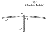
- Fig. 1 shows a portion of a known from the prior art Leitkanranzes with an outer shroud 1 and an airfoil 2, which has an end section 3 having.
- the outer shroud 1 In the outer shroud 1 are a plurality of generally equidistantly arranged Breakthroughs 4 formed.
- an airfoil 2 inserted with its end portion 3 and there by e.g. Soldering or Welding attached.
- the end sections In order to allow the assembly, the end sections must 3 the blades 2 have a two-dimensional or constant profile. Also if the blades 2 are not necessary a constant profile over the entire Channel height must have their profile geometry is subject to assembly reasons significant limitations. The blades 2 must not bend hard or have significant thickening. It is also problematic, the proportionate narrow profiled apertures 4 in the shroud 1 form.
- FIG. 2 shows a plan view of an embodiment of the built-around guide ring, FIG. in which an airfoil 2 in cross-section and at the free end of the Blade 2 subsequent platform 5 is shown.
- an airfoil 2 in cross-section and at the free end of the Blade 2 subsequent platform 5 is shown.
- the surface 8 of the airfoil 2 goes with a transition curvature 9 in the Platt form 6, which is designed so that in the mounted state both to the Surface 8 of the airfoil 2 and to the inner peripheral surface 10 of the Deckbands 1 hugs.
- the transition curvature 9 is formed as a radius which in the central region 11 of the Blade 2 larger than in the region of the leading edge and the trailing edge 12, 13th is and until then, e.g. can gradually decrease.
- the transition curvature 9 along the circumference have a constant radius, wherein in in this case the center of which is so changed towards the entry and exit edges 12, 13 that the circumferential curvature 9 also there to the surface 8 of the airfoil 2 hugs and, as shown in Fig. 7, to the inner peripheral surface 10 of the shroud 1 has a tolerable Tangentensprung. This alternative has manufacturing advantages.
- Fig. 3 shows a sectional view of the shroud 1 and the airfoil 2, at the radius of the transition curvature 9 in the central region 11 of the airfoil 2 is shown.
- the blade 2 is connected to the platform 5 in a breakthrough 4 in the Shroud 1 used, the profile or the shape of the opening 4 the profile or the circumference 6 of the platform 5 corresponds.
- the platform 5 stands with its circumference 6 in this area 11 clearly above the surface 8 of the airfoil 2 before.
- Fig. 4 is a section in the region of the inlet and outlet edge 12, 13 of the airfoil 2 shown.
- the blade 2 is with its platform 5 in the shroud 1 trained breakthrough 4 used and attached.
- the platform 5 points as transition curvature 9 to a radius that is significantly smaller than that in the center region 11, shown in Fig. 3, is, so that the platform 5 with its circumference. 6 protrudes significantly less over the surface 8 of the airfoil 2.
- the radius or the transition curvature 9 nestles on the one hand to the surface 8 of the Blade 2 and on the other hand to the inwardly facing peripheral surface 10th of the shroud 1 on. Due to the significant reduction of the transition radius 9 in Area of the entry and exit edge 12, 13 is the axial length of the built Leitranz effectively reduced.
- the openings 4 in the Make shroud 1 more efficient due to the absence of sharp edges or the like because the circumference 6 of the platform 5 is larger than that of the blade 2.
- the reduction of the axial length in the embodiment 4 manufacturing technology advantageous also with a transition curvature. 9 be achieved with a constant radius along the circumference, if its center, as described above, to the entry and / or exit edge 12, 13 out changes and there is a Tangentensprung T at the transition to the shroud 1 is allowed.
- the Tangentensprung T can at constant radius to the entry and / or exit edge 12, 13 gradually increase.
- Fig. 5 shows another embodiment of the constructed Leitkanranzes, in which a cut airfoil 2 and a platform 5 are shown in plan view.
- the platform 5 stands with its circumference 6 in the central region 11 of the blade 2 or on the pressure and suction side over the surface 8 of the airfoil 2 before and here has a transition curvature 9.
- the platform 5 ends immediately adjacent to the leading edge 12 and the trailing edge 13 and is in these two Not areas above the profile or the circumference 7 of the airfoil 2 before.
- the respectively on both sides of the entry and / or exit edge 12, 13 ending transition curvature 9 is formed to circumferentially contact the surface 8 hugs or there directly at the entry and exit edge 12, 13th expires. In this way, the axial dimensions of the built Leitkranzes effectively reduce without having narrow apertures 4 with sharp edges in the shrouds 1 must be made.
- FIG. 5 While in the embodiment in Fig. 2 to 4 at the entry and exit edge 12, 13 a transition curvature 9 with a much smaller radius (or with the same Radius and changed center and tangent jump) than on the suction and pressure side is present, the embodiment of FIG. 5 in the area of Einund Exit edge 12, 13 formed without transition curvature 9, so that the surface 8 of the airfoil 2 in the assembled state directly to the inner Peripheral surface 10 of the shroud 1 adjacent.
- FIG. 6 shows the embodiment of FIG. 5 in a sectional view, in which the Shroud 1, the blade 2 and the platform 5 directly in the area of the inlet and Exit edge 12, 13 is shown.
- the airfoil 2 at the transition to the platform 5 no transition curvature 9, whereby the axial length is effectively reduced.
- Platform 5 is in this area with its circumference 6 substantially not over the surface 8 of the airfoil 2 and its scope 7 before.
- FIG. 7 shows the embodiment from FIG. 5 in a section shown in FIG. 5 adjacent to the entry and exit edges 12, 13 of the airfoil 2.
- the transition curvature 9 has the same radius as in the central region 11 of the airfoil 2 on.
- the representation of the transition curvature 9 in the central region 11 corresponds in this embodiment, that of the embodiment according to FIG. 2 and is shown in FIG.
Description
Die Erfindung betrifft einen gebauten Leitkranz für eine Gasturbine, umfassend ein Deckband mit einer Umfangsfläche und wenigstens ein Schaufelblatt mit einer Oberfläche, wobei das Deckband wenigstens einen Durchbruch zur Befestigung des Schaufelblatts aufweist, und wobei das Schaufelblatt an wenigstens einem Endabschnitt eine zumindest abschnittsweise über dessen Oberfläche vorstehende, eine Übergangskrümmung aufweisende Plattform aufweist, die in den Durchbruch eingesetzt ist.The invention relates to a built Leitkranz for a gas turbine, comprising a Shroud having a peripheral surface and at least one airfoil having a surface, wherein the shroud has at least one opening for attachment of the Having airfoil, and wherein the airfoil on at least one end portion an at least partially protruding over the surface, a Transition curve having platform used in the breakthrough is.
Gebaute Leitkränze sind integrale Bauteile, die allgemein ein ringförmiges Außendeckband, mehrere Schaufelblätter und ggf. ein ringförmiges Innendeckband umfassen. Derartige Leitkränze können auch segmentweise aufgebaut sein und werden z.B. in Verdichtern von Flugtriebwerken eingesetzt. Das Deckband erstreckt sich im allgemeinen um die Längsachse der Gasturbine herum. Die Schaufelblätter sind im wesentlichen in Radialrichtung angeordnet.Built-Leitkränze are integral components, which is generally an annular outer shroud, comprise a plurality of airfoils and possibly an annular inner shroud. Such Leitkränze can also be constructed in segments and be e.g. used in compressors of aircraft engines. The shroud extends in generally around the longitudinal axis of the gas turbine. The blades are in essentially arranged in the radial direction.
Bei einem bekannten gebauten Leitkranz weist das Schaufelblatt wenigstens einen Endabschnitt mit einem konstanten Profil bzw. einer konstanten Querschnittsfläche auf, welche bei der Montage in einen im Deckband ausgebildeten Durchbruch eingesetzt und durch z.B. Löten oder Schweißen befestigt ist. Das Schaufelblatt kann auch an einem gegenüberliegenden, zweiten Endabschnitt ein konstantes Profil bzw. einen konstanten Querschnitt aufweisen und in einem zweiten Deckband, d.h. einem - Außen- und Innendeckband, eingesetzt sein. Nachteilig dabei ist, dass das Profil des Schaufelblatts zwar nicht über die gesamte Kanalhöhe konstant sein muss, jedoch im Hinblick auf seine Profilgeometrie aus Montagegründen eingeschränkt ist. Das Schaufelblatt darf z.B. keine starke Biegung oder deutliche Verdickung in seinem zwischen den Endabschnitten liegenden Bereich aufweisen. Zudem sind die Durchbrüche im Bereich der Ein- und Austrittskanten bei schmaler Schaufelgeometrie zum Teil sehr eng, was Probleme bei der Fertigung mit sich bringt.In a known built-Leitkranz, the airfoil has at least one End portion with a constant profile or a constant cross-sectional area on, which are used during assembly in a formed in the shroud breakthrough and by e.g. Soldering or welding is attached. The airfoil can too at a opposite, second end portion a constant profile or a have a constant cross-section and in a second shroud, i. one - Outside and inside cover tape to be used. The disadvantage here is that the profile of Although the blade does not have to be constant over the entire channel height, however is limited in terms of its profile geometry for assembly reasons. The Airfoil may be e.g. no strong bend or significant thickening in his have between the end portions lying area. In addition, the breakthroughs in the area of the inlet and outlet edges with narrow blade geometry for Part very tight, which brings problems in the production with it.
Aus der DE 12 00 070 B ist ein Herstellungsverfahren für einen Leitschaufelkranz bekannt, bei dem die Schaufeln in in einem Ringkörper ausgebildete Nuten mit ihrem Schaufelfuß eingesetzt werden, wobei das Schaufelblatt mit einer Krümmung in den Schaufelfuß übergeht und der Ringkörper abschließend in mehrere Segmente getrennt wird. Somit weist das Schaufelblatt an wenigstens einem Ende eine Plattform auf, die im Bereich der Ein- und Austrittskante nur wenig über dessen Oberfläche vorsteht. Im Mittenbereich des Schaufelblatts auf der Druckseite steht die Plattform weiter vor als an der Ein- und Austrittskante. Auf der Saugseite dagegen ist der Überstand der Plattform im Bereich der größten Profildicke praktisch "Null". Stromauf und stromabwärts der größten Profildicke nimmt der Überstand zunächst zu und dann zur Ein- bzw. Austrittskante hin wieder ab.From DE 12 00 070 B is a manufacturing method for a vane ring in which the blades are formed in grooves formed in a ring body with their Blade be used with the blade with a curvature in the Shovel goes over and the ring body finally separated into several segments becomes. Thus, the airfoil has a platform at at least one end on, in the area of the entry and exit edge only slightly above the surface protrudes. In the middle area of the airfoil on the pressure side is the platform further ahead than at the entry and exit edges. On the suction side, however, is the supernatant the platform in the area of the largest profile thickness practically "zero". Upstream and downstream of the largest profile thickness, the supernatant initially increases and then back to the entrance or exit edge.
Die EP 0 704 602 A2 offenbart an einem Träger angeordnete Turbinenschaufeln, bei denen die Schaufelblattoberfläche in einem Radius in die Umfangsfläche des Trägers übergeht.EP 0 704 602 A2 discloses turbine blades arranged on a support the blade surface in a radius in the peripheral surface of the carrier passes.
Ferner ist aus der EP 0 199 073 A1 ein Herstellungsverfahren für eine Leitschaufel bekannt, die durch Löten an einem Leitrad befestigt wird, wobei die Leitschaufel aus einem mit Übermaß abgelenkten Profilstab hergestellt wird, und wobei diesem zur Vergrößerung der Lötfläche an wenigstens einem Ende im kalten Zustand eine fußartige Verdickung angestaucht und in deren Bereich eine Lötfläche ausgebildet wird. Zur Anstellung der Leitschaufeln kann der Profilstab schräg-einseitig angestaucht werden.Furthermore, EP 0 199 073 A1 discloses a manufacturing method for a guide blade known, which is fixed by soldering to a stator, wherein the guide vane an excessively deflected profile bar is produced, and this to the Enlargement of the soldering surface at least one end in the cold state of a foot-like Thickening thickened and in the area of a soldering surface is formed. To adjust the vanes, the profile bar can be upset on one side become.
Die Aufgabe der vorliegenden Erfindung besteht darin, einen gebauten Leitkranz der eingangs beschriebenen Gattung zu schaffen, der axiale Baulänge einspart, festig keitstechnisch günstig ist, sich relativ einfach fertigen lässt und keinen oder nur geringen Einschränkungen im Hinblick auf die Profilgeometrie des Schaufelblatts, z.B. aus Montagegründen, unterliegt.The object of the present invention is a built Leitkranz the to create the genus described above, the axial length saves, fixed keitstechnisch is low, can be relatively easily finished and no or little Limitations on the profile geometry of the airfoil, e.g. for assembly reasons, subject.
Die Lösung der Aufgabe besteht erfindungsgemäß darin, dass die Plattform im Bereich einer Ein- und /oder Austrittskante des Schaufelblatts weniger als im Mittenbereich des Schaufelblatts auf der Saug seite über die Oberfläche des Schaufelblatts vorsteht, oder dass das Schaufelblatt im Bereich der Ein- und Austrittskante keine über dessen Oberfläche vorstehende Plattform aufweist, und so axialer Bauraum eingespart wird. Die Plattform kann mit ihrem Umfang an einen Umfang des Schaufelblatts, der radial in einem der Spitze des Schaufelblatts gegenüberliegenden Bereich liegt, angepasst sein, so dass der Abstand zwischen den beiden vorgenannten Umfängen außer im Bereich der Ein- und/oder Austrittskante im wesentlichen konstant ist.The solution of the task according to the invention is that the platform in the area an entry and / or exit edge of the airfoil less than in the central region of the airfoil on the suction side over the surface of the Projecting airfoil, or that the airfoil in the area of the entry and exit edge does not have over its surface projecting platform, and so on axial space is saved. The platform can with its perimeter to a circumference of the airfoil, which is located radially in one of the tip of the airfoil Range is adjusted, so the distance between the two above-mentioned perimeters except in the area of the entry and / or exit edge in is essentially constant.
Die Übergangskrümmung kann von einem Mittenbereich des Schaufelblatts in Richtung auf die Ein- und/oder Austrittskante zunehmend enger ausgebildet sein.The transition curvature may be from a central region of the airfoil in the direction be formed increasingly narrower on the entry and / or exit edge.
Der Vorteil eines solchen gebauten Leitkranzes besteht darin, dass durch die zusätzlich vorgesehene Plattform des Verbinden von Schaufelblatt und Deckband ohne Einschränkung im Hinblick auf die Profilgeometrie des Schaufelblatts möglich ist. Darüber hinaus bringt die mit einer Übergangskrümmung versehene Plattform im Hinblick auf die Aerodynamik und die Festigkeit Vorteile mit sich. Die Durchbrüche im Deckband weisen im Bereich der Ein- und Austrittskante größere Radien auf und lassen sich besser fertigen.The advantage of such a built Leitranz is that through the addition provided platform of connecting the blade and shroud without Restriction on the profile geometry of the airfoil is possible. In addition, the platform provided with a transition curvature brings in In terms of aerodynamics and strength advantages. The breakthroughs in the shroud have larger radii in the area of the entry and exit edge and can be made better.
In einer Ausgestaltung schmiegt sich die Übergangskrümmung zur optimalen Gestaltung im Hinblick auf Aerodynamik und die Festigkeit an die Oberfläche des Schaufelblatts und die im montierten Zustand an die Plattform angrenzende Umfangsfläche des Deckbands an.In one embodiment, the transition curvature nestles for optimal design in terms of aerodynamics and strength to the surface of the airfoil and in the mounted state adjacent to the platform peripheral surface of the shroud.
Da die Plattform zudem mit ihrem Umfang in die Ein- und/oder Austrittskante jeweils beidseitig ausläuft, tritt das Problem der zu engen und schwer zu fertigenden Kanten in den Durchbrüchen des Deckbands nicht auf.Since the platform also has its circumference in the entry and / or exit edge respectively leaking on both sides, the problem of too narrow and difficult to manufacture edges occurs in the breakthroughs of the shroud not on.
Die Oberfläche des Schaufelblatts kann im Bereich der Ein- und/oder Austrittskante im montierten Zustand an die Umfangsfläche des Deckbands angrenzen, wobei im sonstigen Bereich entlang des Umfangs des Schaufelblatts, z.B. im Mittenbereich auf der Saug- und Druckseite, eine über den Umfang des Schaufelblatts vorstehende Plattform mit einer Übergangskrümmung vorliegt. The surface of the airfoil may be in the region of the entry and / or exit edge in the mounted state adjacent to the peripheral surface of the shroud, wherein in other area along the circumference of the airfoil, e.g. in the middle area the suction and pressure side, a projecting beyond the circumference of the airfoil Platform with a transition curvature exists.
Die Übergangskrümmung kann von einem Mittenbereich des Schaufelblatts, z.B. auf der Saug- und Druckseite, in Richtung auf die Ein- und/oder Austrittskante zunehmend enger ausgebildet sein, so daß aufgrund der engeren Krümmung im Bereich der Ein- und/oder Austrittskante axiale Baulänge eingespart wird.The transition curvature may be from a central region of the airfoil, e.g. on the suction and pressure side, in the direction of the entry and / or exit edge increasingly be formed narrower, so that due to the narrower curvature in the area the entry and / or exit edge axial length is saved.
Die Übergangskrümmung kann wenigstens abschnittsweise kreisförmig ausgebildet sein und einen Radius aufweisen, wobei dieser im Mittenbereich des Schaufelblatts größer als in den anderen Bereichen entlang des Umfangs des Schaufelblatts sein kann. Weist das Schaufelblatt entlang des gesamten Umfangs eine über dessen Umfang vorstehende Plattform auf, so ist der Radius im Bereich der Ein- und/oder Austrittskante zur Verringerung der axialen Baulänge am kleinsten.The transition curvature can be at least partially circular be and have a radius, wherein this in the central region of the airfoil larger than in the other areas along the circumference of the airfoil can. Indicates the airfoil along its entire circumference over its circumference projecting platform, the radius is in the area of the entry and / or exit edge to reduce the axial length smallest.
Bei einem gebauten Leitkranz kann der Radius entlang des Umfangs des Schaufelblatts konstant und sein Mittelpunkt so verändert sein, daß sich die Übergangskrümmung entlang des gesamten Umfangs an die Oberfläche des Schaufelblatts anschmiegt und an der Ein- und/oder Austrittskante ein Tangentensprung zur Umfangsfläche des Deckbands vorliegt. Die Herstellung mit konstantem Radius ist günstig. Zudem wird durch den Tangentensprung an der Ein- und/oder Austrittskante, der bis dorthin sukzessive zunehmen kann, die axiale Baulänge des Leitkranzes verringert.For a constructed nozzle, the radius may be along the circumference of the airfoil constant and its center be changed so that the transition curvature along the entire circumference to the surface of the airfoil snuggles and at the entry and / or exit edge a tangent jump to the peripheral surface of the shroud. The production with constant radius is favorable. In addition, by the Tangentensprung at the entry and / or exit edge, the until there can gradually increase, reduces the axial length of the Leitkanranzes.
Weitere bevorzugte Ausführungsbeispiele der Erfindung sind in den Unteransprüchen beschrieben.Further preferred embodiments of the invention are in the subclaims described.
Im folgenden wir die Erfindung anhand von Ausführungsbeispielen unter Bezugnahme auf eine Zeichnung näher erläutert. Es zeigt:
- Fig. 1
- eine Schnittansicht durch ein Schaufelblatt und ein Deckband aus dem Stand der Technik,
- Fig. 2
- eine Draufsicht auf ein geschnittenes Schaufelblatt samt Plattform gemäß einem Ausführungsbeispiel des erfindungsgemäßen gebauten Leitkranzes,
- Fig. 3
- eine Schnittansicht des Ausführungsbeispiels aus Fig. 2,
- Fig. 4
- eine weitere Schnittansicht des Ausführungsbeispiels aus Fig. 2,
- Fig. 5
- eine Draufsicht auf ein geschnittenes Schaufelblatt samt Plattform gemäß einem anderen Ausführungsbeispiel des erfindungsgemäßen gebauten Leitkranzes,
- Fig. 6
- eine Schnittansicht des Ausführungsbeispiels gemäß Fig. 5 und
- Fig. 7
- eine weitere Schnittansicht des Ausführungsbeispiels gemäß Fig. 5.
- Fig. 1
- a sectional view through an airfoil and a shroud of the prior art,
- Fig. 2
- a plan view of a cut airfoil including platform according to an embodiment of the constructed Leitkanranzes invention,
- Fig. 3
- a sectional view of the embodiment of FIG. 2,
- Fig. 4
- a further sectional view of the embodiment of FIG. 2,
- Fig. 5
- a top view of a cut airfoil with platform according to another embodiment of the constructed Leitkanranzes invention,
- Fig. 6
- a sectional view of the embodiment of FIG. 5 and
- Fig. 7
- a further sectional view of the embodiment of FIG. 5.
Fig. 1 zeigt einen Abschnitt eines aus dem Stand der Technik bekannten Leitkranzes
mit einem äußeren Deckband 1 und einem Schaufelblatt 2, das einen Endabschnitt 3
aufweist. In dem äußeren Deckband 1 sind mehrere, im allgemeinen äquidistant angeordnete
Durchbrüche 4 ausgebildet. In jeden Durchbruch 4 wird jeweils ein Schaufelblatt
2 mit seinem Endabschnitt 3 eingesetzt und dort durch z.B. Löten oder
Schweißen befestigt. Um die Montage zu ermöglichen, müssen die Endabschnitte 3
der Schaufelblätter 2 ein zwei-dimensionales bzw. konstantes Profil aufweisen. Auch
wenn die Schaufelblätter 2 nicht notwendig ein konstantes Profil über die gesamte
Kanalhöhe besitzen müssen, unterliegt deren Profilgeometrie aus Montagegründen
deutlichen Einschränkungen. Die Schaufelblätter 2 dürfen keine starke Biegung oder
deutliche Verdickungen besitzen. Es ist zudem problematisch, die verhältnismäßig
schmal profilierten Durchbrüche 4 in dem Deckband 1 auszubilden.Fig. 1 shows a portion of a known from the prior art Leitkanranzes
with an outer shroud 1 and an
Fig. 2 zeigt eine Draufsicht auf ein Ausführungsbeispiel des gebauten Leitkranzes,
bei dem ein Schaufelblatt 2 im Querschnitt und eine sich an das freie Ende des
Schaufelblatts 2 anschließende Plattform 5 dargestellt ist. In diesem Fall entspricht
das Profil bzw. die Form des Durchbruchs 4 in dem Deckband 1 dem Profil bzw. Umfang
6 der Plattform 5 und ist größer als der Umfang 7 des Schaufelblatts 2. Die Oberfläche
8 des Schaufelblatts 2 geht mit einer Übergangskrümmung 9 in die Platt
form 6 über, die so gestaltet ist, daß sie sich im montierten Zustand sowohl an die
Oberfläche 8 des Schaufelblatts 2 als auch an die innere Umfangsfläche 10 des
Deckbands 1 anschmiegt.FIG. 2 shows a plan view of an embodiment of the built-around guide ring, FIG.
in which an
Die Übergangskrümmung 9 ist als Radius ausgebildet, der im Mittenbereich 11 des
Schaufelblatts 2 größer als im Bereich der Eintrittskante und Austrittskante 12, 13
ist und bis dorthin z.B. sukzessive abnehmen kann. Alternativ kann die Übergangskrümmung
9 entlang des Umfangs einen konstanten Radius aufweisen, wobei sich in
diesem Fall dessen Mittelpunkt zur Ein- und Austrittskante 12, 13 hin so verändert,
daß sich die Umfangskrümmung 9 auch dort an die Oberfläche 8 des Schaufelblatts
2 anschmiegt und, wie in Fig. 7 dargestellt, zur inneren Umfangsfläche 10 des Deckbands
1 hin einen tolerierbaren Tangentensprung aufweist. Diese Alternative hat
fertigungstechnische Vorteile.The
Fig. 3 zeigt eine geschnittene Ansicht des Deckbands 1 und des Schaufelblatts 2, bei
dem der Radius der Übergangskrümmung 9 im Mittenbereich 11 des Schaufelblatts
2 dargestellt ist. Die Schaufel 2 ist mit der Plattform 5 in einen Durchbruch 4 in das
Deckband 1 eingesetzt, wobei das Profil bzw. die Form des Durchbruchs 4 dem Profil
bzw. dem Umfang 6 der Plattform 5 entspricht. Die Plattform 5 steht mit ihrem Umfang
6 in diesem Bereich 11 deutlich über die Oberfläche 8 des Schaufelblatts 2 vor.Fig. 3 shows a sectional view of the shroud 1 and the
In Fig. 4 ist ein Schnitt im Bereich der Ein- und Austrittskante 12, 13 des Schaufelblatts
2 dargestellt. Das Schaufelblatt 2 ist mit seiner Plattform 5 in den im Deckband
1 ausgebildeten Durchbruch 4 eingesetzt und befestigt. Die Plattform 5 weist
als Übergangskrümmung 9 einen Radius auf, der deutlich kleiner als jener im Mittenbereich
11, dargestellt in Fig. 3, ist, so daß die Plattform 5 mit ihrem Umfang 6
deutlich weniger über die Oberfläche 8 des Schaufelblatts 2 vorsteht. Der Radius
bzw. die Übergangskrümmung 9 schmiegt sich einerseits an die Oberfläche 8 des
Schaufelblatts 2 und andererseits an die nach innen gewandte Umfangsfläche 10
des Deckbands 1 an. Durch die deutliche Verkleinerung des Übergangsradius 9 im
Bereich der Ein- und Austrittskante 12, 13 wird die axiale Baulänge des gebauten
Leitkranzes wirksam verringert. Gleichzeitig lassen sich die Durchbrüche 4 in dem
Deckband 1 aufgrund des Fehlens von spitzen Kanten oder dgl. effizienter fertigen,
da der Umfang 6 der Plattform 5 großflächiger als jener vom Schaufelblatt 2 ist.In Fig. 4 is a section in the region of the inlet and
Alternativ kann die Verringerung der axialen Baulänge bei dem Ausführungsbeispiel
gemäß Fig. 4 fertigungstechnisch vorteilhaft auch mit einer Übergangskrümmung 9
mit konstantem Radius entlang des Umfangs erzielt werden, wenn sich dessen Mittelpunkt,
wie oben beschrieben, zur Ein- und/oder Austrittskante 12, 13 hin ändert
und dort einen Tangentensprung T beim Übergang zum Deckband 1 zugelassen wird. Alternatively, the reduction of the axial length in the
Der Tangentensprung T kann bei konstantem Radius zur Ein- und/oder Austrittskante
12, 13 hin sukzessive zunehmen.The Tangentensprung T can at constant radius to the entry and / or
Fig. 5 zeigt ein weiteres Ausführungsbeispiel des gebauten Leitkranzes, bei dem ein
geschnittenes Schaufelblatt 2 und eine Plattform 5 in der Draufsicht dargestellt sind.
Die Plattform 5 steht mit ihrem Umfang 6 im Mittenbereich 11 des Schaufelblatts 2
bzw. an der Druck- und Saugseite über die Oberfläche 8 des Schaufelblatts 2 vor und
weist hier eine Übergangskrümmung 9 auf. Die Plattform 5 endet unmittelbar angrenzend
an die Eintrittskante 12 und die Austrittskante 13 und steht in diesen beiden
Bereichen nicht über das Profil bzw. den Umfang 7 des Schaufelblatts 2 vor. Die
jeweils zu beiden Seiten der Ein- und/oder Austrittskante 12, 13 endende Übergangskrümmung
9 wird so ausgebildet, daß sie sich in Umfangsrichtung an die Oberfläche
8 anschmiegt bzw. dort unmittelbar an der Ein- und Austrittskante 12, 13
ausläuft. Auf diese Weise lassen sich die axialen Abmessungen des gebauten Leitkranzes
wirksam verringern, ohne daß schmale Durchbrüche 4 mit spitzen Kanten in
den Deckbändern 1 gefertigt werden müssen.Fig. 5 shows another embodiment of the constructed Leitkanranzes, in which a
Während in dem Ausführungsbeispiel in Fig. 2 bis 4 an der Ein- und Austrittskante
12, 13 eine Übergangskrümmung 9 mit deutlich kleinerem Radius (bzw. mit demselben
Radius und verändertem Mittelpunkt und Tangentensprung) als auf der Saug
und Druckseite vorliegt, wird das Ausführungsbeispiel aus Fig. 5 im Bereich der Einund
Austrittskante 12, 13 ohne Übergangskrümmung 9 ausgebildet, so daß die Oberfläche
8 des Schaufelblatts 2 im montierten Zustand unmittelbar an die innere
Umfangsfläche 10 des Deckbands 1 angrenzt.While in the embodiment in Fig. 2 to 4 at the entry and
Fig. 6 zeigt das Ausführungsbeispiel aus Fig. 5 in einer Schnittansicht, in der das
Deckband 1, das Schaufelblatt 2 und die Plattform 5 unmittelbar im Bereich der Einund
Austrittskante 12, 13 dargestellt ist. In dieser Ausgestaltung weist das Schaufelblatt
2 am Übergang zur Plattform 5 keine Übergangskrümmung 9 auf, wodurch
die axiale Baulänge wirksam reduziert wird. Die Plattform 5 steht in diesem Bereich
mit ihrem Umfang 6 im wesentlichen nicht über die Oberfläche 8 des Schaufelblatts
2 bzw. dessen Umfang 7 vor. Fig. 6 shows the embodiment of FIG. 5 in a sectional view, in which the
Shroud 1, the
Fig. 7 zeigt das Ausführungsbeispiel aus Fig. 5 in einem in Fig. 5 gezeigten Schnitt
angrenzend an die Ein- und Austrittskante 12, 13 des Schaufelblatts 2. Die Übergangskrümmung
9 weist denselben Radius wie im Mittenbereich 11 des Schaufelblatts
2 auf. Die Darstellung der Übergangskrümmung 9 im Mittenbereich 11 entspricht
bei diesem Ausführungsbeispiel jener des Ausführungsbeispiels gemäß Fig. 2
und ist in Fig. 3 gezeigt.FIG. 7 shows the embodiment from FIG. 5 in a section shown in FIG. 5
adjacent to the entry and exit edges 12, 13 of the
Aufgrund des fertigungstechnisch vorteilhaften, konstanten Radius bei gleichzeitigem
Verschieben von dessen Mittelpunkt in der Weise, daß sich die Übergangskrümmung
9 entlang des gesamten Umfangs 7 an die Oberfläche 8 des Schaufelblatts
2 anschmiegt und bis angrenzend an die Ein- und/oder Austrittskante 12, 13
ein zunehmender Tangentensprung T zur inneren Oberfläche 10 des Deckbands 1
vorliegt, wird die axiale Läge des Leitkranzes verringert.Due to the manufacturing technology advantageous, constant radius at the same time
Move from its center in such a way that the
Die beispielhaft an einem äußeren Deckband beschriebenen Maßnahmen können in entsprechender Weise an einem zusätzlichen inneren Deckband verwirklicht werden.The measures described as an example on an outer shroud can in corresponding manner be realized on an additional inner shroud.
Claims (8)
- An assembled blade rim for a gas turbine comprising a shroud (1) with a peripheral surface (10) and at least one blade (2) with a surface (8), the shroud (1) having at least one opening (4) for fixing the blade (2) and the blade (2) having at at least one end section (3) a platform (5) with a transitional curve (9), at least some sections of which project beyond its surface (8), which is inserted into the opening (4), the platform (5) projecting beyond the surface (8) of the blade (2) in the central area (11) of the blade (2) on the suction and pressure side, and the platform (5) projecting less beyond the surface of the blade in the area of a leading and/or trailing edge (12, 13) of the blade (2) than in the central area (11) of the blade on the pressure side,
characterised in that
the platform (5) projects less beyond the surface of the blade (2) in the area of a leading and/or trailing edge (12, 13) of the blade (2) than in the central area (11) of the blade (2) or that the blade (2) has no platform (5) projecting beyond its surface (8) in the area of the leading and/or trailing edge (12, 13). - An assembled blade rim in accordance with claim 1,
characterised in that
the periphery (6) of the platform (5) is adapted to a periphery (7) of the blade (2). - An assembled blade rim in accordance with claim 1 or 2,
characterised in that
the transitional curve (9) is designed to narrow from a central area (11) of the blade (2) towards a leading and/or trailing edge (12, 13). - An assembled blade rim in accordance with one of the preceding claims,
characterised in that
the transitional curve (9) conforms to the surface (8) of the blade (2) and to an adjacent peripheral surface (10) of the shroud (1). - An assembled blade rim in accordance with one of the preceding claims,
characterised in that
the surface (8) of the blade (2) lies adjacent to the peripheral surface (10) of the shroud (1) in the area of the leading and/or trailing edge (12, 13). - An assembled blade rim in accordance with one of the preceding claims,
characterised in that
at least sections of the transitional curve (9) are designed as a radius. - An assembled blade rim in accordance with claim 6,
characterised in that
the radius is greater in a central area (11) of the blade (2) than in the other areas along the periphery (7) of the blade (2). - An assembled blade rim in accordance with claim 7,
characterised in that
the radius along the periphery (7) of the blade (2) is constant while its mid-point varies such that the transitional curve (9) conforms to the surface (8) of the blade (2) along the entire periphery (7) and there is a tangential distance (T) to the peripheral surface (10) of the shroud (1) at the leading and/or trailing edge (12, 13).
Applications Claiming Priority (2)
| Application Number | Priority Date | Filing Date | Title |
|---|---|---|---|
| DE19941133A DE19941133C1 (en) | 1999-08-30 | 1999-08-30 | Blade crown ring for gas turbine aircraft engine has each blade provided with curved transition region between blade surface and blade platform fitting in opening in carrier band |
| DE19941133 | 1999-08-30 |
Publications (3)
| Publication Number | Publication Date |
|---|---|
| EP1081336A2 EP1081336A2 (en) | 2001-03-07 |
| EP1081336A3 EP1081336A3 (en) | 2003-10-01 |
| EP1081336B1 true EP1081336B1 (en) | 2005-02-02 |
Family
ID=7920103
Family Applications (1)
| Application Number | Title | Priority Date | Filing Date |
|---|---|---|---|
| EP00115821A Expired - Lifetime EP1081336B1 (en) | 1999-08-30 | 2000-07-22 | Vane ring assembly for gas turbines |
Country Status (3)
| Country | Link |
|---|---|
| US (1) | US6543998B1 (en) |
| EP (1) | EP1081336B1 (en) |
| DE (2) | DE19941133C1 (en) |
Families Citing this family (13)
| Publication number | Priority date | Publication date | Assignee | Title |
|---|---|---|---|---|
| FR2899270A1 (en) * | 2006-03-30 | 2007-10-05 | Snecma Sa | LOCALLY-SHAPED RECTIFIER RAM, RECTIFIER AREA, COMPRESSION STAGE, COMPRESSOR AND TURBOMACHINE COMPRISING SUCH A BLADE |
| FR2899269A1 (en) * | 2006-03-30 | 2007-10-05 | Snecma Sa | OPTIMIZED RECTIFIER BLADE, RECTIFIER AREA, COMPRESSION FLOOR, COMPRESSOR AND TURBOMACHINE COMPRISING SUCH A BLADE |
| US7748956B2 (en) * | 2006-12-19 | 2010-07-06 | United Technologies Corporation | Non-stablug stator apparatus and assembly method |
| US8740557B2 (en) * | 2009-10-01 | 2014-06-03 | Pratt & Whitney Canada Corp. | Fabricated static vane ring |
| US8920117B2 (en) * | 2011-10-07 | 2014-12-30 | Pratt & Whitney Canada Corp. | Fabricated gas turbine duct |
| US9840929B2 (en) * | 2013-05-28 | 2017-12-12 | Pratt & Whitney Canada Corp. | Gas turbine engine vane assembly and method of mounting same |
| US9869190B2 (en) | 2014-05-30 | 2018-01-16 | General Electric Company | Variable-pitch rotor with remote counterweights |
| US20160017731A1 (en) * | 2014-07-17 | 2016-01-21 | Rolls-Royce Corporation | Vane assembly |
| US10072510B2 (en) | 2014-11-21 | 2018-09-11 | General Electric Company | Variable pitch fan for gas turbine engine and method of assembling the same |
| US9988918B2 (en) * | 2015-05-01 | 2018-06-05 | General Electric Company | Compressor system and airfoil assembly |
| US10100653B2 (en) | 2015-10-08 | 2018-10-16 | General Electric Company | Variable pitch fan blade retention system |
| US11674435B2 (en) | 2021-06-29 | 2023-06-13 | General Electric Company | Levered counterweight feathering system |
| US11795964B2 (en) | 2021-07-16 | 2023-10-24 | General Electric Company | Levered counterweight feathering system |
Family Cites Families (9)
| Publication number | Priority date | Publication date | Assignee | Title |
|---|---|---|---|---|
| US2681788A (en) * | 1951-05-23 | 1954-06-22 | Solar Aircraft Co | Gas turbine vane structure |
| FR1095927A (en) * | 1953-02-02 | 1955-06-07 | Bristol Aeroplane Co Ltd | Improvements to the mounting of wing profile vanes in compressors and other applications |
| DE1200070B (en) * | 1961-11-21 | 1965-09-02 | Siemens Ag | Process for the production of guide vane ring segments for gas turbines |
| FR1389254A (en) * | 1963-04-08 | 1965-02-12 | Rolls Royce | Compressor for gas turbine engine |
| US4260327A (en) * | 1979-07-25 | 1981-04-07 | General Electric Company | Guide vane assembly for reverse flow cooled dynamoelectric machine |
| DE3514122A1 (en) * | 1985-04-19 | 1986-10-23 | MAN Gutehoffnungshütte GmbH, 4200 Oberhausen | METHOD FOR PRODUCING A GUIDE BLADE FOR A TURBINE OR COMPRESSOR LEAD, AND GUIDE BLADE PRODUCED BY THE METHOD |
| US5474419A (en) * | 1992-12-30 | 1995-12-12 | Reluzco; George | Flowpath assembly for a turbine diaphragm and methods of manufacture |
| GB9417406D0 (en) * | 1994-08-30 | 1994-10-19 | Gec Alsthom Ltd | Turbine blade |
| US5765993A (en) * | 1996-09-27 | 1998-06-16 | Chromalloy Gas Turbine Corporation | Replacement vane assembly for fan exit guide |
-
1999
- 1999-08-30 DE DE19941133A patent/DE19941133C1/en not_active Expired - Fee Related
-
2000
- 2000-07-22 DE DE50009400T patent/DE50009400D1/en not_active Expired - Fee Related
- 2000-07-22 EP EP00115821A patent/EP1081336B1/en not_active Expired - Lifetime
- 2000-08-25 US US09/645,483 patent/US6543998B1/en not_active Expired - Fee Related
Also Published As
| Publication number | Publication date |
|---|---|
| US6543998B1 (en) | 2003-04-08 |
| DE19941133C1 (en) | 2000-12-28 |
| DE50009400D1 (en) | 2005-03-10 |
| EP1081336A2 (en) | 2001-03-07 |
| EP1081336A3 (en) | 2003-10-01 |
Similar Documents
| Publication | Publication Date | Title |
|---|---|---|
| DE19941134C1 (en) | Blade crown ring for gas turbine aircraft engine has each blade provided with transition region between blade surface and blade platform having successively decreasing curvature radii | |
| DE19929978B4 (en) | Fan with axial blades | |
| DE19518203C2 (en) | Device for receiving an inner guide vane end in an axial compressor | |
| DE69921320T2 (en) | TURBINENSTATORSCHAUFEL | |
| EP1081336B1 (en) | Vane ring assembly for gas turbines | |
| EP3176370B1 (en) | Blade cluster for a flow machine | |
| EP2505783B1 (en) | Rotor of an axial compressor stage of a turbo machine | |
| EP0661413A1 (en) | Axial blade cascade with blades of arrowed leading edge | |
| EP2478186B1 (en) | Rotor of a turbomachine | |
| DE102007002326A1 (en) | Turbine blade and vane construction | |
| DE3148985C2 (en) | ROTOR ASSEMBLY | |
| EP2505851B1 (en) | Stator stage of an axial compressor for a turbomachine | |
| DE3835622A1 (en) | RADIAL COMPRESSORS | |
| DE60019965T2 (en) | AXIAL TURBINE FOR GASES | |
| EP3056677B1 (en) | Blade and flow engine | |
| EP2994615B1 (en) | Rotor for a thermal turbomachine | |
| EP2410131A2 (en) | Rotor of a turbomachine | |
| EP1706595B1 (en) | Non-positive-displacement machine comprising a spiral channel provided in the housing middle part | |
| DE3844158A1 (en) | CASCADE PUMP MECHANISM | |
| DE2244805A1 (en) | FAN | |
| EP2607626A1 (en) | Turbomachine and stage of a turbomachine | |
| DE3049897A1 (en) | Exhaust pipe of turbine | |
| EP3109520B1 (en) | Seal carrier, guide blade assembly and fluid flow engine | |
| DE102009007664A1 (en) | Sealing device on the blade shank of a rotor stage of an axial flow machine | |
| DE60002781T2 (en) | Hub-axis connection |
Legal Events
| Date | Code | Title | Description |
|---|---|---|---|
| PUAI | Public reference made under article 153(3) epc to a published international application that has entered the european phase |
Free format text: ORIGINAL CODE: 0009012 |
|
| AK | Designated contracting states |
Kind code of ref document: A2 Designated state(s): AT BE CH CY DE DK ES FI FR GB GR IE IT LI LU MC NL PT SE |
|
| AX | Request for extension of the european patent |
Free format text: AL;LT;LV;MK;RO;SI |
|
| RAP1 | Party data changed (applicant data changed or rights of an application transferred) |
Owner name: MTU AERO ENGINES GMBH |
|
| PUAL | Search report despatched |
Free format text: ORIGINAL CODE: 0009013 |
|
| AK | Designated contracting states |
Kind code of ref document: A3 Designated state(s): AT BE CH CY DE DK ES FI FR GB GR IE IT LI LU MC NL PT SE |
|
| AX | Request for extension of the european patent |
Extension state: AL LT LV MK RO SI |
|
| 17P | Request for examination filed |
Effective date: 20031008 |
|
| 17Q | First examination report despatched |
Effective date: 20040212 |
|
| AKX | Designation fees paid |
Designated state(s): DE ES FR GB IT |
|
| GRAP | Despatch of communication of intention to grant a patent |
Free format text: ORIGINAL CODE: EPIDOSNIGR1 |
|
| GRAS | Grant fee paid |
Free format text: ORIGINAL CODE: EPIDOSNIGR3 |
|
| GRAA | (expected) grant |
Free format text: ORIGINAL CODE: 0009210 |
|
| AK | Designated contracting states |
Kind code of ref document: B1 Designated state(s): DE ES FR GB IT |
|
| REG | Reference to a national code |
Ref country code: GB Ref legal event code: FG4D Free format text: NOT ENGLISH |
|
| REG | Reference to a national code |
Ref country code: IE Ref legal event code: FG4D Free format text: GERMAN |
|
| REF | Corresponds to: |
Ref document number: 50009400 Country of ref document: DE Date of ref document: 20050310 Kind code of ref document: P |
|
| GBT | Gb: translation of ep patent filed (gb section 77(6)(a)/1977) |
Effective date: 20050318 |
|
| PG25 | Lapsed in a contracting state [announced via postgrant information from national office to epo] |
Ref country code: ES Free format text: LAPSE BECAUSE OF FAILURE TO SUBMIT A TRANSLATION OF THE DESCRIPTION OR TO PAY THE FEE WITHIN THE PRESCRIBED TIME-LIMIT Effective date: 20050513 |
|
| PLBE | No opposition filed within time limit |
Free format text: ORIGINAL CODE: 0009261 |
|
| STAA | Information on the status of an ep patent application or granted ep patent |
Free format text: STATUS: NO OPPOSITION FILED WITHIN TIME LIMIT |
|
| ET | Fr: translation filed | ||
| 26N | No opposition filed |
Effective date: 20051103 |
|
| PGFP | Annual fee paid to national office [announced via postgrant information from national office to epo] |
Ref country code: FR Payment date: 20090716 Year of fee payment: 10 |
|
| PGFP | Annual fee paid to national office [announced via postgrant information from national office to epo] |
Ref country code: DE Payment date: 20090722 Year of fee payment: 10 Ref country code: GB Payment date: 20090720 Year of fee payment: 10 |
|
| PGFP | Annual fee paid to national office [announced via postgrant information from national office to epo] |
Ref country code: IT Payment date: 20090725 Year of fee payment: 10 |
|
| GBPC | Gb: european patent ceased through non-payment of renewal fee |
Effective date: 20100722 |
|
| REG | Reference to a national code |
Ref country code: FR Ref legal event code: ST Effective date: 20110331 |
|
| PG25 | Lapsed in a contracting state [announced via postgrant information from national office to epo] |
Ref country code: DE Free format text: LAPSE BECAUSE OF NON-PAYMENT OF DUE FEES Effective date: 20110201 |
|
| REG | Reference to a national code |
Ref country code: DE Ref legal event code: R119 Ref document number: 50009400 Country of ref document: DE Effective date: 20110201 |
|
| PG25 | Lapsed in a contracting state [announced via postgrant information from national office to epo] |
Ref country code: FR Free format text: LAPSE BECAUSE OF NON-PAYMENT OF DUE FEES Effective date: 20100802 Ref country code: IT Free format text: LAPSE BECAUSE OF NON-PAYMENT OF DUE FEES Effective date: 20100722 |
|
| PG25 | Lapsed in a contracting state [announced via postgrant information from national office to epo] |
Ref country code: GB Free format text: LAPSE BECAUSE OF NON-PAYMENT OF DUE FEES Effective date: 20100722 |