EP2622244B2 - Gear wheel arrangement and method for producing a bayonet catch - Google Patents
Gear wheel arrangement and method for producing a bayonet catch Download PDFInfo
- Publication number
- EP2622244B2 EP2622244B2 EP11810994.1A EP11810994A EP2622244B2 EP 2622244 B2 EP2622244 B2 EP 2622244B2 EP 11810994 A EP11810994 A EP 11810994A EP 2622244 B2 EP2622244 B2 EP 2622244B2
- Authority
- EP
- European Patent Office
- Prior art keywords
- hub
- toothed wheel
- projections
- gear
- rotatable
- Prior art date
- Legal status (The legal status is an assumption and is not a legal conclusion. Google has not performed a legal analysis and makes no representation as to the accuracy of the status listed.)
- Active
Links
- 238000004519 manufacturing process Methods 0.000 title claims description 10
- 238000003754 machining Methods 0.000 claims description 16
- 238000000034 method Methods 0.000 claims description 11
- 238000005245 sintering Methods 0.000 claims description 10
- 230000007704 transition Effects 0.000 claims description 7
- 239000000463 material Substances 0.000 description 7
- 230000015572 biosynthetic process Effects 0.000 description 6
- 230000008901 benefit Effects 0.000 description 5
- 210000002105 tongue Anatomy 0.000 description 5
- 230000002093 peripheral effect Effects 0.000 description 4
- 239000000843 powder Substances 0.000 description 4
- 230000008569 process Effects 0.000 description 4
- 229910000831 Steel Inorganic materials 0.000 description 2
- 238000009826 distribution Methods 0.000 description 2
- 238000007654 immersion Methods 0.000 description 2
- 230000006872 improvement Effects 0.000 description 2
- 239000010959 steel Substances 0.000 description 2
- 241000538562 Banjos Species 0.000 description 1
- 229910000639 Spring steel Inorganic materials 0.000 description 1
- 230000008859 change Effects 0.000 description 1
- 238000010276 construction Methods 0.000 description 1
- 230000008878 coupling Effects 0.000 description 1
- 238000010168 coupling process Methods 0.000 description 1
- 238000005859 coupling reaction Methods 0.000 description 1
- 238000005520 cutting process Methods 0.000 description 1
- 238000000280 densification Methods 0.000 description 1
- 238000005516 engineering process Methods 0.000 description 1
- 238000007373 indentation Methods 0.000 description 1
- 238000009434 installation Methods 0.000 description 1
- 238000011068 loading method Methods 0.000 description 1
- 239000000314 lubricant Substances 0.000 description 1
- 238000003801 milling Methods 0.000 description 1
- 238000002156 mixing Methods 0.000 description 1
- 238000002360 preparation method Methods 0.000 description 1
- 238000003825 pressing Methods 0.000 description 1
- 238000007789 sealing Methods 0.000 description 1
Images


Classifications
-
- F—MECHANICAL ENGINEERING; LIGHTING; HEATING; WEAPONS; BLASTING
- F16—ENGINEERING ELEMENTS AND UNITS; GENERAL MEASURES FOR PRODUCING AND MAINTAINING EFFECTIVE FUNCTIONING OF MACHINES OR INSTALLATIONS; THERMAL INSULATION IN GENERAL
- F16H—GEARING
- F16H55/00—Elements with teeth or friction surfaces for conveying motion; Worms, pulleys or sheaves for gearing mechanisms
- F16H55/02—Toothed members; Worms
- F16H55/17—Toothed wheels
- F16H55/18—Special devices for taking up backlash
-
- F—MECHANICAL ENGINEERING; LIGHTING; HEATING; WEAPONS; BLASTING
- F16—ENGINEERING ELEMENTS AND UNITS; GENERAL MEASURES FOR PRODUCING AND MAINTAINING EFFECTIVE FUNCTIONING OF MACHINES OR INSTALLATIONS; THERMAL INSULATION IN GENERAL
- F16H—GEARING
- F16H55/00—Elements with teeth or friction surfaces for conveying motion; Worms, pulleys or sheaves for gearing mechanisms
- F16H55/02—Toothed members; Worms
- F16H55/17—Toothed wheels
-
- B—PERFORMING OPERATIONS; TRANSPORTING
- B22—CASTING; POWDER METALLURGY
- B22F—WORKING METALLIC POWDER; MANUFACTURE OF ARTICLES FROM METALLIC POWDER; MAKING METALLIC POWDER; APPARATUS OR DEVICES SPECIALLY ADAPTED FOR METALLIC POWDER
- B22F5/00—Manufacture of workpieces or articles from metallic powder characterised by the special shape of the product
- B22F5/08—Manufacture of workpieces or articles from metallic powder characterised by the special shape of the product of toothed articles, e.g. gear wheels; of cam discs
-
- Y—GENERAL TAGGING OF NEW TECHNOLOGICAL DEVELOPMENTS; GENERAL TAGGING OF CROSS-SECTIONAL TECHNOLOGIES SPANNING OVER SEVERAL SECTIONS OF THE IPC; TECHNICAL SUBJECTS COVERED BY FORMER USPC CROSS-REFERENCE ART COLLECTIONS [XRACs] AND DIGESTS
- Y10—TECHNICAL SUBJECTS COVERED BY FORMER USPC
- Y10T—TECHNICAL SUBJECTS COVERED BY FORMER US CLASSIFICATION
- Y10T74/00—Machine element or mechanism
- Y10T74/19—Gearing
- Y10T74/1987—Rotary bodies
- Y10T74/19893—Sectional
- Y10T74/19916—Multiple disks
Definitions
- the invention relates to a gear arrangement having a main gear and a relative to this relatively circumferentially rotatable gear, wherein the main gear has a gear body on which in the axial direction above a hub on the one hand for receiving a shaft and on the other hand for arranging the rotatable gear is arranged thereon the rotatable gear has a recess coaxial with an axially extending central axis of the main gear, and wherein the main gear is connected to the rotatable gear by means of a bayonet coupling formed between the hub and the rotatable gear, wherein hub protrusions project radially outward from the hub are formed and in the axial direction between the hub projections and the gear body extending in the direction of the circumference of the hub undercut in the form of a groove, wherein in the recess of the rotatable gear radially inwardly projecting V wherein an inner diameter between two opposing projections has a size which corresponds at least approximately to an outer diameter of the hub in
- the invention further relates to a method for producing a bayonet closure for a main gear and a relative to this relatively circumferentially rotatable gear having gear assembly according to the invention, wherein the main gear has a gear body on which in the axial direction above a hub on the one hand for receiving a shaft and on the other hand Arrangement of the rotatable gear is arranged thereon, for which purpose the rotatable gear has a coaxial with an axially extending central axis of the main gear recess.
- Such a gear arrangement is, for example, from that of the applicant WO 2005/090830 A1 is known, which is a gear for a backlash-free spur gear with a hub, with a hub supported by the sprocket, which is divided along an axis normal division plane in two sub-rings, namely in a hub-fixed collar part and in a coaxially rotatably mounted relative to this ring ring, and with a hub surrounding the annular spring, which is formed with their mutually circumferentially opposite ends integrally formed with the two sub-rings, overlapping each other in the axial direction supporting webs, which are arranged in the circumferential direction of the ring gear one behind the other.
- the support web of a sub-rim passes through the other sub-rim in a passage opening with clearance in the circumferential direction and forms the support web of the sub-rim with the passage opening a mounting stop limiting mounting stop for the other support web.
- the ring collar is secured axially on the hub, for example by means of a snap ring.
- a gear assembly comprising two gears, one of which is rotatably disposed against the other within certain limits.
- the two gears are coupled together via a spring element.
- the spring element is made in one piece with one of the gears.
- a bayonet lock can be arranged in order to secure the axial position of the two gears to each other after adjusting the position of the teeth to each other.
- the JP 08-159242 A describes a gear arrangement according to the preamble of claim 1, comprising a main gear and a rotatable gear.
- the main gear has a hub on which the rotatable gear is arranged.
- the two gears are connected by a bayonet lock. These are provided on the main gear on the hub in the radial direction extending, strip-shaped projections.
- the rotatable gear has corresponding slots through which the projections can be guided during assembly.
- the formation of the bayonet lock between the hub, which receives the shaft on which the gear arrangement is arranged, and the rotatable gear is achieved that an additional hub on the main gear is not required, whereby the structure of the gear arrangement simplified and with respect to the distribution of forces between the main gear and the rotatable gear during operation of the gear assembly forces can be improved.
- the assembly of the gear arrangement is simpler, as can be dispensed with an additional axial securing to secure the relative position of the two gears in the axial direction to each other.
- the main gear is produced by sintering.
- the hub projections as part of the bayonet closure so that a subsequent machining is required to form the "groove" between the closure elements and the gear body of the main gear.
- the main gear is made on the hub with recesses in the region of the circumference of the hub, which form in the finished main gear, the gaps between the closure elements in the circumferential direction, which allow the passage of the corresponding projections on the rotatable gear to form the bayonet closure.
- the inventive method has the advantage that by forming an obtuse angle between the side walls and the bottom surfaces of the recesses - viewed in the circumferential direction - better protection of the machining tool when re-immersion in the material is achieved, so that the life of the tool can be extended , In addition, this ensures that the formation of burrs in the area of the machining of the main gear is reduced.
- radially outwardly projecting hub projections are arranged on the hub. It is thus a relatively simple production of the bayonet closure allows, which can be done in particular after a sintering process.
- These radially outwardly projecting hub projections can also be formed in terms of their cross-sectional area - viewed in the axial direction of the gear assembly - relatively large area, whereby a better wear behavior by the presence of a large contact surface of the closure elements of the bayonet catch of the rotatable gear on the closure elements of the bayonet lock of the main gear, i. the hub projections, can be achieved.
- the hub projections are arranged symmetrically distributed over the circumference of the hub, so that the contact surfaces of the rotatable gear on the main gear are distributed uniformly over the circumference of the main gear, and thus distributes the forces acting uniformly over the entire circumference of the gear assembly can be. This positively influences the wear behavior.
- the undercut extends continuously over the circumference of the hub to facilitate the assembly of the gear assembly, since thus the rotatable gear on both sides of the hub projections can be pushed onto the hub.
- the hub projections in the circumferential direction of the hub have an overall length of between 20%, in particular 40%, preferably 50%, and 80%, in particular 60%, of the length of the circumference the hub is.
- the hub projections viewed in the axial direction, ie in plan view of the plane surface, a trapezoidal cross-section.
- the assembly of the gear arrangement is simplified.
- the manufacture of the bayonet closure is thereby improved by, as has already been explained above, thereby reducing the wear of the machining tools.
- the angle between the at least a side surfaces and the bottom surfaces is selected from a range having a lower limit of 95 °, in particular 100 °, and an upper limit of 130 °, in particular 120 °.
- angles from this angular range have proved to be particularly advantageous in practice.
- edges, preferably all edges, of the recesses are rounded or chamfered, whereby a further improvement with regard to the service life of the tool can be achieved, namely in the area of immersion of the tool in the material of Main gear of the angle in which the recessed surfaces are the tool is designed dull for this area, but at the same time this obtuse angle is limited only to the edge region, so that the removal rate of the material is not reduced.
- this i.
- the contact surface of the rotatable gear on the main gear in the assembled state of the gear arrangement is not reduced so much that the advantages of even loading of the bayonet closure over the circumference of the hub would be degraded ,
- the rotatable gear is also produced by sintering, wherein radially inwardly extending projections are formed in the recess of the gear. It is thus possible without substantial finishing the production of the rotatable gear, with complex bayonet geometries are formed without the rotatable gear would have to be subjected to a machining reworking.
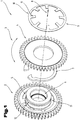
- Fig. 1 shows in exploded view a gear arrangement 1, as it is known from the prior art.
- This gear arrangement 1, also called “split gear”, has a main gear 2 and a relative to this relatively rotatable in a circumferential direction 3 gear 4, wherein the main gear 2 has a hub 5, which is in particular integrally formed with the main gear 2.
- the rotatable gear 4 is rotatably mounted on the hub 5 of the main gear 2.
- the hub 5 has a recess 6 in the form of a bore for receiving a shaft, not shown.
- the rotatable gear 4 is biased in the circumferential direction 3 relative to the main gear 2 by means of a spring element 7, which is in this case so-called ⁇ - spring, as shown in the WO 2005/090830 A1 is thus included in this scope of the basic structure of the gear assembly 1 to the content of this description.
- a spring element 7 is formed, which forms an assembly stop for another support web.
- the spring element 7 abuts against these support webs with its two open end regions.
- another spring element 9 which in this embodiment, the form of a plate spring, in particular a slotted plate spring to be designated in the broadest sense, arranged.
- This further spring element 9 has an outer ring 10, from which obliquely pointing radially inwards a plurality of tongues 11, so-called spring tongues, protrude. These tongues 11 are received by a circumferential groove 12, which is formed in an end portion 13 of the hub 5. By the spring tension is thus the further rotatable gear 4 in the axial direction biased against the main gear.
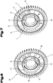
- the Fig. 2 to 7 show a first embodiment of the gear arrangement 1 according to the invention.
- Fig. 2 in turn, the main gear 2 and the adjacent thereto rotatable gear 4 can be seen.
- the rotatable gear 4 is arranged on the hub 5.
- This embodiment variant of the gear arrangement has, inter alia, the advantage that the additional spring element 9 of the embodiment according to Fig. 1 for axial securing of the rotatable gear 4 is not required.
- the biasing force for the rotatable gear 4 in the circumferential direction 3 by the spring element 7, for example, the ⁇ - spring, are generated.
- a bayonet 14 is arranged between the hub 5 of the main gear 2 and the rotatable gear 4.
- the rotatable gear 4 also has projections 16, which, however, extending radially inwardly in a recess 17 (FIG. Fig. 5 ) are arranged.
- the recess 17 is formed coaxially with the hub 5 and serves to be able to postpone the rotatable gear 4 to the hub 5 of the main gear 2.
- an inner diameter 18 between two opposing projections 16, as shown in FIG Fig. 5 is shown, a size which corresponds at least approximately to an outer diameter 19 of the hub in the region between recesses 20, wherein the recesses 20 are formed in the circumferential direction 3 between two adjacent hub projections 15 on the hub.
- the inner diameter 18 at least the outer diameter 19 corresponds in terms of its dimension, but preferably is slightly larger, so that the rotatable gear 4 can be easily pushed onto the hub 5.
- the recesses 20 between two hub projections 15 have a width 21 in the circumferential direction 3, which is at least as large as a width 22 (FIG. Fig. 5 ) of the projections 16 on the rotatable gear 4 in the same direction, so that the projections 16 can be inserted into these recesses 20.
- the width 21 is slightly greater than the width 22. It is further preferred if the recesses 20 in the axial direction of the gear arrangement 1 have a cross section which corresponds at least approximately to the cross section in the same direction of the projections 16 of the rotatable gear 4.
- an undercut 23 is formed in the form of a groove, as in particular from Fig. 4 can be seen.
- the hub projections 15 are thus spaced apart in the axial direction from an end face 24 (FIG. Fig. 7 ) of a gear body 25 of the main gear 2 - the main gear 2 consists of the gear body 25 and the hub 5 - arranged.
- a width 26 of the undercut 23 or the groove is chosen such that it has a size which is at least approximately a width 27 (FIG. Fig. 5 ) in the axial direction of the projections 16 of the rotatable gear 4, wherein at least approximately means that the width 26 of the undercut 23 is selected so that the rotatable gear 4 can be rotated in the circumferential direction 3.
- a facing in the direction of the gear body 25 of the main gear 2 end face 28 ( Fig. 3 ) of the hub projections 15 are aligned coplanar with the direction of the hub projections 15 facing end face 24 of the gear body 25 so that the undercut 23 in the circumferential direction 3 of the gear assembly has a rectangular or square cross-section.
- this end face 28 it is also possible for this end face 28 to be arranged at an oblique angle to the end face 24 of the gear body 25, so that the undercuts 23 narrow in the circumferential direction.
- a higher contact pressure of the rotatable gear 4 is achieved to the main gear 2 in a certain position, on the other hand, so that the rotatability of the rotatable gear 4 can be limited.
- the limitation of the rotatability of the rotatable gear 4 in the circumferential direction 3 of the gear assembly 1 can also be achieved so that the undercut 23 in the circumferential direction 3 is not continuous, so that the hub projections 15 are only partially spaced from the end face 24 of the gear body 25 of the main gear 2 ,
- the undercut 23 in the circumferential direction 3 is designed to be continuous, so that thus an annular groove is formed in the axial direction is open to the front in the region of the recesses 20.
- a groove bottom 29 ( Fig. 3 ) is preferably formed planar with a bottom surface 30 of the recesses 20.
- the groove bottom 29 is offset in the radial direction against this bottom surface, for example, is formed deeper, so as to form a "lubricant groove".
- the groove bottom 29 may be considered to be higher than the bottom surfaces 30 of the recesses 20 in the radial direction from the longitudinal central axis through the gear assembly 1, in which case the projections 16 of the rotatable gear 4 must be adjusted, ie a height 31 of the projections 16 in the radial direction is smaller than a height 32 of the hub projections 15, the difference resulting from the height difference in the radial direction between the groove bottom 29 and the bottom surface 30.
- the rotatable gear 4 is placed on the hub 5, wherein the projections 16 of the rotatable gear 4 are positioned in the axial direction in alignment with the recesses 20 of the hub 5, then the rotatable gear 4 in the axial direction in the direction pushed onto the gear body 25 of the main gear 2 and when the projections 16 of the rotatable gear 4 in the axial direction behind the hub projections 15 are circumferentially 3 rotated against the main gear, whereby on the projections 16 and the hub projections 15 of the bayonet lock 14 for axially securing the rotatable Gear 4 is made relative to the main gear 2.
- the spring element 7 can be arranged between the rotatable gear 4 and the main gear 2.
- a securing element 33 is pushed through the two gears, to which both the rotatable gear 4 and the Main gear 2 each have a recess 34 or 35 in the form of an opening. After installation of the gear arrangement 1, this securing element 33 is removed again.
- each six hub projections 15 and six projections 16 and accordingly six recesses 20 are shown, in the invention, a different number of hub projections 15, projections 16 and recesses 20 may be provided, for example, three, four, five, seven, eight, etc .. ..
- the hub projections 15 of the main gear 2 and the projections 16 of the rotatable gear 4 are arranged symmetrically about the circumference of the hub 5 and the recess 17 of the rotatable gear 4, that is between the distances between the hub projections 15 and projections 16 are equal are, as in the Fig. 2 to 5 is shown.
- the hub projections 15 in the direction of the circumference of the hub 5 have an overall length which is between 20%, in particular 40%, preferably 50%, and 80%, in particular 60%, of the length of the circumference of the hub 5 , In this case, the length of the circumference of the hub 5 in height of the bottom surface 30 of the recesses 20 - viewed in the radial direction - measured.
- At least transitions 36 between an axially forwardly facing end face 37 of the hub projections 15 and a peripheral surface 38 in the radially upper region of the hub projections 15 are rounded or chamfered.
- all transitions between the axially outwardly facing end face of the hub 5 and the circumferential surface of the hub 5 can be rounded or beveled, ie also the transitions in the area of the bottom surfaces 30 of the recesses 20 (it should be noted that the hub projections 15 are preferably in one piece formed with the hub, so that the peripheral surfaces 38 of the hub projections 15 form part of the total circumference of the hub 5).
- the main gear 2 is preferably made in one piece by a sintering process, that is, the hub 5 and the gear body 25 do not consist of two separate parts.
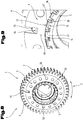
- a preform 39 as in Fig. 6 is prepared, for example, by the usual steps, such as optionally powder mixing, powder pressing in a mold, sintering, optionally after re-densification and / or calibration produced.
- this preform 39 differs from the finished gear only in that the undercut 23 or the (ring) groove between the thus not yet finished hub projections 15 and the gear body 25 is not yet formed, as the comparison of 6 and 7 shows.
- This undercut 23 is produced by the sintering process in a cutting process step with a tool, such as a chisel or by milling. Since the preform already has the recesses 20 between the hub projections 15 still to be finished, and recess end walls 40 of the recesses 20 are removed during the machining, the tool partially re-dips into the material of the hub 5 several times during the entire machining process. Thus, a higher tool wear and an increased burr formation are connected by the interrupted cut in the processing zone.
- a tool such as a chisel or by milling.
- the hub projections 15 at least partially have a trapezoidal cross-section when viewed in the axial direction.
- the cross section of the hub projections 15 can also be composed of several geometric shapes, for example, the cross section consists of a rectangle with attached trapezoid.
- a second side wall 42 of the recesses 20 and the hub projections 15, which is formed in the circumferential direction on the first side wall 41 following, against the bottom surface 30th is inclined, with an angle greater than 90 °.
- Embodiments of the cross-section which are symmetrical, that is, the two at least partially inclined side surfaces 41, 42 include the same angular value with the bottom surface 30, so that the cross section of the hub projections 15 at least partially, preferably entirely, has an isosceles trapezoid in the axial direction ,
- the angle which at least one of the side surfaces 41, 42 encloses with the bottom surface 30 is preferably selected from a range with a lower limit of 95 °, in particular 100 °, and an upper limit of 130 °, in particular 120 °.
- the projections 16 of the rotatable gear 4 have a cross section, which follow the contour of the recesses 30 of the hub 5, although this is the preferred embodiment of the gear assembly 1.
- an annular web 45 is formed, via which the rotatable gear 2 rests on the gear body 25 of the main gear 2, as in Fig. 4 is shown.
- a recess 46 in the form of an annular groove for receiving the spring element 7 between the rotatable gear 4 and the main gear 2 are created.
- This recess 46 can also be created at least partially by a corresponding indentation in the gear body 25 of the main gear 2.
- this ring land 45 can also be arranged on the gear body 25 of the main gear 2, or there is the possibility that both the rotatable gear 4 and the main gear 2 have such a ring land 45.
- annular groove for receiving the annular web 45 is arranged in order to achieve better guidance of the rotatable gear 4 on the main gear 2 during rotation.
- the rotatable gear 4 is recessed in a region 47 of the abutment of the projections 16 on the hub projections 15, so that the projections 16 are not in one plane with a main body 48 of the rotatable gear 4 above the region 47, as in Fig. 5 is shown in order to improve the training of the banjo zipper between the two gears.
- the 8 and 9 show a non-inventive embodiment of the gear assembly 1 in an oblique view or detail view with the main gear 2, the adjacent thereto rotatable gear 4 and the spring element 9, in particular a plate spring.
- the bayonet closure 14 is formed in this embodiment of the gear arrangement 1 between the hub 5 and serving as an axial securing spring element 9.
- the hub 5 in turn on the radially outwardly projecting hub projections 15.
- the projections 16 are also provided, which are however arranged unlike the above embodiment on the spring element 9 and are arranged by a spring element body 49 projecting radially inwardly in a recess 50 of the spring element 9.
- the recess 50 is sized, i. its diameter, so dimensioned that the spring element 9 can be pushed onto the hub 5, to which the projections 16 on the spring element 9, as in the above embodiment, the projections 16 are pushed through the recesses 20 between the hub projections 15.
- no annular groove for receiving the projections 16 of the spring element 9 is formed behind the hub projections 15, but the top walls 43 and top surfaces are angled, so so - viewed in the circumferential direction 3 of the gear assembly 1 - the hub projections in Area of the cover walls 43 have an at least approximately triangular cross-section.
- an edge-like center elevation 51 is dimensioned such that a circle following the center elevations of all hub projections 15 has a diameter 52 which is greater than a smallest inner diameter of the spring element 9, which is defined by the end regions of the tongue-shaped projections 16 of the spring element 9.
- the diameter defined by the hub projections 15 becomes smaller again - in comparison to the diameter defined by the edge-shaped center elevations 51 - so that the projections 16 of the spring element can be pushed onto the cover walls 43 of the hub projections 15 like this in Fig. 9 shown in detail.
- the center elevations 51 of the hub projections 15 do not necessarily have to be edge-shaped.
- these center elevations 51 can also be flattened, resulting in a step-shaped course in the area of the cover walls 43 with regard to the cross section of the hub projections 15.
- the center elevations 15 extend as far as an outer end face 53 of the hub projections 15.
- the spring element 9 is provided with an anti-rotation 54, which is designed in the illustrated embodiment as a tab which is bent in the direction of the rotatable gear 4 and is received in a recess 55 of the rotatable gear 4.
- an anti-rotation 54 which is designed in the illustrated embodiment as a tab which is bent in the direction of the rotatable gear 4 and is received in a recess 55 of the rotatable gear 4.
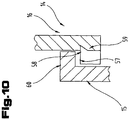
- Fig. 10 shows a variant of a bayonet closure 14.
- the hub projections 15 and the projections 16 of the rotatable gear 4 (not shown) in cross-section - in the circumferential direction 3 (eg Fig. 8 ) - each provided with an undercut 57, 58, so that the hub projections 15 and the projections 16 of the rotatable gear 4 are angular and engage bends 59 of the projections 16 of the rotatable gear 4 below bends 60 of the hub projections 15.
- the bends 59, 60 thereby run at least approximately in the axial direction of the gear arrangement 1.
- the main gear 2 and the rotatable gear 4 are preferably made of a sintered steel
- the further spring element 9 consists of a spring steel
Landscapes
- Engineering & Computer Science (AREA)
- General Engineering & Computer Science (AREA)
- Mechanical Engineering (AREA)
- Manufacturing & Machinery (AREA)
- Gears, Cams (AREA)
Description
Die Erfindung betrifft eine Zahnradanordnung mit einem Hauptzahnrad und einem gegenüber diesem relativ in Umfangsrichtung verdrehbaren Zahnrad, wobei das Hauptzahnrad einen Zahnradkörper aufweist, auf dem in axialer Richtung vorstehend eine Nabe einerseits zur Aufnahme einer Welle und andererseits zur Anordnung des verdrehbaren Zahnrades darauf angeordnet ist, wobei das verdrehbare Zahnrad eine zu einer axial verlaufenden Mittelachse des Hauptzahnrades koaxiale Ausnehmung aufweist, und wobei das Hauptzahnrad mit dem verdrehbaren Zahnrad mittels eines Bajonettverschlusses verbunden ist, der zwischen der Nabe und dem verdrehbaren Zahnrad ausgebildet ist, wobei an der Nabe radial nach außen ragende Nabenvorsprünge angeordnet sind und in axialer Richtung zwischen den Nabenvorsprüngen und dem Zahnradkörper eine in Richtung des Umfanges der Nabe verlaufende Hinterschneidung in Form einer Nut ausgebildet ist, wobei in der Ausnehmung des verdrehbaren Zahnrades radial nach innen ragende Vorsprünge ausgebildet sind, und wobei ein Innendurchmesser zwischen zwei einander gegenüberliegenden Vorsprüngen eine Größe aufweist, die zumindest annähernd einem Außendurchmesser der Nabe im Bereich von Ausnehmungen entspricht, die in Umfangsrichtung zwischen zwei nebeneinander angeordneten Nabenvorsprüngen an der Nabe ausgebildet sind. Weiter betrifft die Erfindung ein Verfahren zur Herstellung eines Bajonettverschlusses für eine ein Hauptzahnrad und ein gegenüber diesem relativ in Umfangsrichtung verdrehbares Zahnrad aufweisende erfindungsgemäße Zahnradanordnung, wobei das Hauptzahnrad einen Zahnradkörper aufweist, auf dem in axialer Richtung vorstehend eine Nabe einerseits zur Aufnahme einer Welle und andererseits zur Anordnung des verdrehbaren Zahnrades darauf angeordnet ist, wozu das verdrehbare Zahnrad eine zu einer axial verlaufenden Mittelachse des Hauptzahnrades koaxiale Ausnehmung aufweist.The invention relates to a gear arrangement having a main gear and a relative to this relatively circumferentially rotatable gear, wherein the main gear has a gear body on which in the axial direction above a hub on the one hand for receiving a shaft and on the other hand for arranging the rotatable gear is arranged thereon the rotatable gear has a recess coaxial with an axially extending central axis of the main gear, and wherein the main gear is connected to the rotatable gear by means of a bayonet coupling formed between the hub and the rotatable gear, wherein hub protrusions project radially outward from the hub are formed and in the axial direction between the hub projections and the gear body extending in the direction of the circumference of the hub undercut in the form of a groove, wherein in the recess of the rotatable gear radially inwardly projecting V wherein an inner diameter between two opposing projections has a size which corresponds at least approximately to an outer diameter of the hub in the region of recesses formed in the circumferential direction between two adjacent hub projections on the hub. The invention further relates to a method for producing a bayonet closure for a main gear and a relative to this relatively circumferentially rotatable gear having gear assembly according to the invention, wherein the main gear has a gear body on which in the axial direction above a hub on the one hand for receiving a shaft and on the other hand Arrangement of the rotatable gear is arranged thereon, for which purpose the rotatable gear has a coaxial with an axially extending central axis of the main gear recess.
Eine derartige Zahnradanordnung ist beispielsweise aus der von der Anmelderin stammenden
Aus der
Die
Es ist die Aufgabe der vorliegenden Erfindung, eine eingangs genannte Zahnradanordnung hinsichtlich der Verbindung der beiden Zahnräder miteinander zu verbessern. Es ist weiters eine Teilaufgabe der Erfindung, ein verbessertes Verfahren zur Herstellung der Zahnradanordnung anzugeben.It is the object of the present invention to improve an aforementioned gear arrangement with respect to the connection of the two gears with each other. It is a further object of the invention to provide an improved method of manufacturing the gear assembly.
Diese Aufgabe der Erfindung wird durch die eingangs genannte Zahnradanordnung gelöst, bei der durch den Bajonettverschluss eine Axialsicherung für das verdrehbare Zahnrad gebildet ist und damit die relative Lage des verdrehbaren Zahnrades in axialer Richtung der Zahnradanordnung fixiert wird, wobei eine Breite der Hinterschneidung eine Größe aufweist, die zumindest annähernd einer Breite der Vorsprünge des verdrehbaren Zahnrades in axialer Richtung entspricht.This object of the invention is achieved by the gear arrangement mentioned above, in which by the bayonet lock an axial securing is formed for the rotatable gear and thus the relative position of the rotatable gear in the axial direction of the gear arrangement is fixed, wherein a width of the undercut has a size which corresponds at least approximately to a width of the projections of the rotatable gear in the axial direction.
Die Aufgabe wird weiters durch das eingangs genannte Verfahren gelöst, dass die Schritte umfasst:
- sintertechnische Herstellung einer einstückigen Vorform für das Hauptzahnrad aus dem Zahnradkörper und der Nabe, wobei am Umfang der Nabe von einer Stirnfläche der Nabe beginnend, in axialer Richtung auf den Zahnradkörper verlaufende Vertiefungen ausgebildet werden, die sich bis zu einem, der Stirnfläche der Nabe in axialer Richtung gegenüberliegenden Ausnehmungsendwand erstrecken, und die jeweils zwei Seitenwände und eine Bodenfläche aufweisen, wobei zumindest eine der Seitenwände einen Winkel zur Bodenfläche der Ausnehmung einschließt, der größer als 90 ° ist;
- spanende Bearbeitung der Nabe der Vorform in Umfangsrichtung, wodurch die Ausnehmungsendwände entfernt und teilweise Hinterschneidungen gebildet werden, wodurch Nabenvorsprünge gebildet werden, die einen Teil des Bajonettverschlusses bilden.
- sintered production of a one-piece preform for the main gear from the gear body and the hub, wherein on the circumference of the hub starting from an end face of the hub, extending in the axial direction on the gear body depressions are formed, extending to one, the end face of the hub in the axial Extend towards the opposite recess end wall, and each having two side walls and a bottom surface, wherein at least one of the side walls forms an angle to the bottom surface of the recess, which is greater than 90 °;
- machining the hub of the preform circumferentially, thereby removing the recess end walls and partially forming undercuts, thereby forming hub protrusions forming part of the bayonet closure.
Durch die Ausbildung des Bajonettverschlusses zwischen der Nabe, die die Welle aufnimmt, auf der die Zahnradanordnung angeordnet wird, und dem verdrehbaren Zahnrad wird erreicht, dass eine zusätzliche Nabe auf dem Hauptzahnrad nicht erforderlich ist, wodurch der Aufbau der Zahnradanordnung vereinfacht und hinsichtlich der Kräfteverteilung der zwischen dem Hauptzahnrad und dem verdrehbaren Zahnrad im Betrieb der Zahnradanordnung auftretenden Kräfte verbessert werden kann. Zudem ist damit der Zusammenbau der Zahnradanordnung einfacher, da auf eine zusätzliche Axialsicherung zur Sicherung der relativen Lage der beiden Zahnräder in axialer Richtung zueinander verzichtet werden kann.The formation of the bayonet lock between the hub, which receives the shaft on which the gear arrangement is arranged, and the rotatable gear is achieved that an additional hub on the main gear is not required, whereby the structure of the gear arrangement simplified and with respect to the distribution of forces between the main gear and the rotatable gear during operation of the gear assembly forces can be improved. In addition, the assembly of the gear arrangement is simpler, as can be dispensed with an additional axial securing to secure the relative position of the two gears in the axial direction to each other.
Bevorzugt wird das Hauptzahnrad sintertechnisch hergestellt. Zur Ausbildung der Nabenvorsprünge als Teil des Bajonettverschlusses ist damit eine nachträgliche spanende Bearbeitung erforderlich, um die "Nut" zwischen den Verschlusselementen und dem Zahnradkörper des Hauptzahnrades auszubilden. In Vorbereitung der Verschlusselemente wird das Hauptzahnrad an der Nabe mit Ausnehmungen im Bereich des Umfanges der Nabe hergestellt, die beim fertigen Hauptzahnrad die Zwischenräume zwischen den Verschlusselementen in Umfangsrichtung bilden, die das Durchschieben der entsprechenden Vorsprünge am verdrehbaren Zahnrad zur Ausbildung des Bajonettverschlusses ermöglichen. Bei der späteren spanenden Nachbearbeitung trifft das Bearbeitungswerkzeug in diesen Bereichen also teilweise auf "Freistellungen" (durch die Entfernung der Ausnehmungsendwände) sodass das Bearbeitungswerkzeug mehrmals - über den Umfang der Nabe betrachtet - in das Material der Nabe eintaucht. Hierbei weist das erfindungsgemäße Verfahren den Vorteil auf, dass durch die Ausbildung eines stumpfen Winkels zwischen den Seitenwänden und der Bodenflächen der Ausnehmungen - in Umfangsrichtung betrachtet - eine bessere Schonung des Bearbeitungswerkzeuges beim Wiedereintauchen in das Material erreicht wird, sodass die Standzeit des Werkzeuges verlängert werden kann. Zudem wird damit erreicht, dass die Gratbildung im Bereich der spanenden Bearbeitung des Hauptzahnrades reduziert wird.Preferably, the main gear is produced by sintering. For the formation of the hub projections as part of the bayonet closure so that a subsequent machining is required to form the "groove" between the closure elements and the gear body of the main gear. In preparation of the closure elements, the main gear is made on the hub with recesses in the region of the circumference of the hub, which form in the finished main gear, the gaps between the closure elements in the circumferential direction, which allow the passage of the corresponding projections on the rotatable gear to form the bayonet closure. During the subsequent machining, the machining tool thus partially encounters "free positions" in these areas (due to the removal of the recess end walls) so that the machining tool is immersed several times over the circumference of the hub into the material of the hub. In this case, the inventive method has the advantage that by forming an obtuse angle between the side walls and the bottom surfaces of the recesses - viewed in the circumferential direction - better protection of the machining tool when re-immersion in the material is achieved, so that the life of the tool can be extended , In addition, this ensures that the formation of burrs in the area of the machining of the main gear is reduced.
Zur Ausbildung des Bajonettverschlusses sind an der Nabe radial nach außen ragende Nabenvorsprünge angeordnet. Es wird damit eine relativ einfache Fertigung des Bajonettverschlusses ermöglicht, die insbesondere auch nach einem Sinterverfahren erfolgen kann. Diese radial nach außen ragenden Nabenvorsprünge können zudem hinsichtlich ihrer Querschnittsfläche - in axialer Richtung der Zahnradanordnung betrachtet - relativ großflächig ausgebildet werden, wodurch ein besseres Verschleißverhalten durch das Vorhandensein einer großen Anlagefläche der Verschlusselemente des Bajonettverschlusses des verdrehbaren Zahnrades an den Verschlusselementen des Bajonettverschlusses des Hauptzahnrades, d.h. den Nabenvorsprüngen, erreicht werden kann.To form the bayonet catch radially outwardly projecting hub projections are arranged on the hub. It is thus a relatively simple production of the bayonet closure allows, which can be done in particular after a sintering process. These radially outwardly projecting hub projections can also be formed in terms of their cross-sectional area - viewed in the axial direction of the gear assembly - relatively large area, whereby a better wear behavior by the presence of a large contact surface of the closure elements of the bayonet catch of the rotatable gear on the closure elements of the bayonet lock of the main gear, i. the hub projections, can be achieved.
In axialer Richtung ist zwischen den Nabenvorsprüngen und dem Zahnradkörper eine in Richtung des Umfanges der Nabe verlaufende, Hinterschneidung ausgebildet, wodurch die Verschlussfestigkeit des Bajonettverschlusses verbessert werden kann.In the axial direction between the hub projections and the gear body is formed extending in the direction of the circumference of the hub, undercut, whereby the sealing strength of the bayonet lock can be improved.
Zur Ausbildung des Bajonettverschlusses sind in der Ausnehmung des verdrehbaren Zahnrades radial nach innen ragende Vorsprünge ausgebildet, da mit dieser Ausführung die sintertechnische Herstellung des verdrehbaren Zahnrades vereinfacht werden kann, indem die Pressformen einfacher ausgestaltet werden können.To form the bayonet catch radially inwardly projecting projections are formed in the recess of the rotatable gear, since with this embodiment, the sintering technology of the rotatable gear can be simplified by the press molds can be made simpler.
Gemäß einer Ausführungsvariante ist vorgesehen, dass die Nabenvorsprünge symmetrisch verteilt über den Umfang der Nabe angeordnet sind, sodass die Anlageflächen des verdrehbaren Zahnrades am Hauptzahnrad gleichmäßig über den Umfang des Hauptzahnrades verteilt angeordnet sind, und damit die einwirkenden Kräfte gleichmäßig über den gesamten Umfang der Zahnradanordnung verteilt werden können. Es wird damit das Verschleißverhalten positiv beeinflusst.According to one embodiment, it is provided that the hub projections are arranged symmetrically distributed over the circumference of the hub, so that the contact surfaces of the rotatable gear on the main gear are distributed uniformly over the circumference of the main gear, and thus distributes the forces acting uniformly over the entire circumference of the gear assembly can be. This positively influences the wear behavior.
Vorzugsweise erstreckt sich die Hinterschneidung durchgehend über den Umfang der Nabe, um den Zusammenbau der Zahnradanordnung zu vereinfachen, da damit des verdrehbare Zahnrad beidseitig der Nabenvorsprünge auf die Nabe aufgeschoben werden kann.Preferably, the undercut extends continuously over the circumference of the hub to facilitate the assembly of the gear assembly, since thus the rotatable gear on both sides of the hub projections can be pushed onto the hub.
In Hinblick auf einer Reduzierung des Verschleißes der Zahnradanordnung ist es von Vorteil, wenn die Nabenvorsprünge in Umfangsrichtung der Nabe eine Gesamtlänge aufweisen, die zwischen 20 %, insbesondere 40 %, vorzugsweise 50 %, und 80 %, insbesondere 60 %, der Länge des Umfanges der Nabe beträgt.In view of reducing the wear of the gear assembly, it is advantageous if the hub projections in the circumferential direction of the hub have an overall length of between 20%, in particular 40%, preferably 50%, and 80%, in particular 60%, of the length of the circumference the hub is.
Bevorzugt weisen die Nabenvorsprünge in axialer Richtung betrachtet, also in Draufsicht auf die Planfläche, einen trapezförmigen Querschnitt auf. Einerseits wird damit der Zusammenbau der Zahnradanordnung vereinfacht. Insbesondere wird damit aber die Herstellung des Bajonettverschlusses verbessert, indem, wie dies voranstehend bereits erläutert wurde, damit der Verschleiß der Bearbeitungswerkzeuge reduziert wird.Preferably, the hub projections viewed in the axial direction, ie in plan view of the plane surface, a trapezoidal cross-section. On the one hand so that the assembly of the gear arrangement is simplified. In particular, however, the manufacture of the bayonet closure is thereby improved by, as has already been explained above, thereby reducing the wear of the machining tools.
Zur Vereinfachung des Zusammenbaus der Zahnradanordnung kann vorgesehen sein, dass ein Übergang zwischen einer Stirnfläche der Nabe und der Umfangsfläche im Bereich der Nabenvorsprünge gerundet oder gefast ausgebildet ist, da damit das Aufschieben des verdrehbaren Zahnrades auf die Nabe des Hauptzahnrades vereinfacht werden kann.To simplify the assembly of the gear arrangement can be provided that a transition between an end face of the hub and the peripheral surface in the hub projections is rounded or beveled, since thus the sliding of the rotatable gear can be simplified to the hub of the main gear.
Gemäß einer Ausführungsvariante des Verfahrens ist vorgesehen, dass der Winkel zwischen den zumindest einen Seitenflächen und den Bodenflächen ausgewählt wird aus einem Bereich mit einer unteren Grenze von 95 °, insbesondere 100 °, und einer oberen Grenze von 130 °, insbesondere 120 °. Hinsichtlich der Werkzeugschonung und der Bearbeitungsgeschwindigkeit haben sich in der Praxis Winkel aus diesem Winkelbereich als besonders vorteilhaft erwiesen.According to one embodiment variant of the method, it is provided that the angle between the at least a side surfaces and the bottom surfaces is selected from a range having a lower limit of 95 °, in particular 100 °, and an upper limit of 130 °, in particular 120 °. With regard to tool protection and machining speed, angles from this angular range have proved to be particularly advantageous in practice.
Es kann auch vorgesehen werden, dass zumindest einzelne Kanten, bevorzugt sämtliche Kanten, der Ausnehmungen gerundet oder gefast ausgebildet werden, wodurch eine weitere Verbesserung in Hinblick auf die Standzeit des Werkzeuges erreicht werden kann, indem nämlich im Bereich des Eintauchens des Werkzeuges in das Material des Hauptzahnrades der Winkel, in dem die Ausnehmungsflächen zum Werkzeug stehen, für diesen Bereich stumpfer ausgebildet ist, wobei aber gleichzeitig dieser stumpfere Winkel nur auf den Kantenbereich beschränkt ist, sodass die Abtraggeschwindigkeit des Materials nicht verringert wird. Zudem wird damit, d.h. durch die im Vergleich zum Kantenbereich mit einem kleineren Winkel zur Bodenfläche angeordneten Seitenflächen der Ausnehmungen, die Anlagefläche des verdrehbaren Zahnrades an dem Hauptzahnrad im zusammengebauten Zustand der Zahnradanordnung nicht so weit verringert, dass die Vorteile der gleichmäßigen Beanspruchung des Bajonettverschlusses über den Umfang der Nabe verschlechtert würde.It can also be provided that at least individual edges, preferably all edges, of the recesses are rounded or chamfered, whereby a further improvement with regard to the service life of the tool can be achieved, namely in the area of immersion of the tool in the material of Main gear of the angle in which the recessed surfaces are the tool is designed dull for this area, but at the same time this obtuse angle is limited only to the edge region, so that the removal rate of the material is not reduced. In addition, with this, i. due to the side surfaces of the recesses arranged at a smaller angle to the bottom surface compared to the edge region, the contact surface of the rotatable gear on the main gear in the assembled state of the gear arrangement is not reduced so much that the advantages of even loading of the bayonet closure over the circumference of the hub would be degraded ,
Vorzugsweise wird das verdrehbare Zahnrad ebenfalls sintertechnisch hergestellt, wobei radial nach innen verlaufende Vorsprünge in der Ausnehmung des Zahnrades geformt werden. Es ist damit ohne wesentliche Nachbearbeitung die Fertigung des verdrehbaren Zahnrades möglich, wobei auch komplexe Bajonettgeometrien ausbildbar sind, ohne dass das verdrehbare Zahnrad einer spanenden Nachbearbeitung unterzogen werden müsste.Preferably, the rotatable gear is also produced by sintering, wherein radially inwardly extending projections are formed in the recess of the gear. It is thus possible without substantial finishing the production of the rotatable gear, with complex bayonet geometries are formed without the rotatable gear would have to be subjected to a machining reworking.
Für eine bessere Anlage des verdrehbaren Zahnrades am Hauptzahnrad kann vorgesehen werden, dass an einer in radialer Richtung verlaufenden Stirnfläche des verdrehbaren Zahnrades ein Ringsteg ausgebildet wird.For a better contact of the rotatable gear on the main gear can be provided that at an extending in the radial direction of the end face of the rotatable gear an annular web is formed.
Zum besseren Verständnis der Erfindung wird diese anhand der nachfolgenden Figuren näher erläutert.For a better understanding of the invention, this will be explained in more detail with reference to the following figures.
Es zeigen jeweils in stark schematisch vereinfachter Darstellung:
- Fig. 1
- eine Zahnradgruppe gemäß dem Stand der Technik in Explosionsdarstellung;
- Fig. 2
- eine erste Ausführungsvariante einer erfindungsgemäßen Zahnradgruppe in Schrägansicht;
- Fig. 3
- ein Detail der Zahnradanordnung nach
Fig. 2 ; - Fig. 4
- ein Detail der Zahnradanordnung nach
Fig. 2 in Seitenansicht geschnitten; - Fig. 5
- das verdrehbare Zahnrad der Ausführungsvariante nach
Fig. 2 in Schrägansicht; - Fig. 6
- eine Vorform des Hauptzahnrades der Ausführungsvariante nach
Fig. 2 in Schrägansicht; - Fig. 7
- das Hauptzahnrad nach
Fig. 6 in Schrägansicht nach einer spanenden Bearbeitung; - Fig. 8
- eine nicht erfindungsgemäße Ausführungsvariante einer Zahnradgruppe in Schrägansicht;
- Fig. 9
- ein Detail der Zahnradanordnung nach
Fig. 8 ; - Fig. 10
- ein Detail einer Ausführungsvariante eines Bajonettverschlusses im Querschnitt.
- Fig. 1
- a gear group according to the prior art in exploded view;
- Fig. 2
- a first embodiment of a gear group according to the invention in an oblique view;
- Fig. 3
- a detail of the gear arrangement after
Fig. 2 ; - Fig. 4
- a detail of the gear arrangement after
Fig. 2 cut in side view; - Fig. 5
- the rotatable gear of the embodiment according to
Fig. 2 in an oblique view; - Fig. 6
- a preform of the main gear of the embodiment according to
Fig. 2 in an oblique view; - Fig. 7
- the main gear to
Fig. 6 in an oblique view after a machining operation; - Fig. 8
- a non-inventive embodiment of a gear group in an oblique view;
- Fig. 9
- a detail of the gear arrangement after
Fig. 8 ; - Fig. 10
- a detail of a variant of a bayonet closure in cross section.
Einführend sei festgehalten, dass in den unterschiedlich beschriebenen Ausführungsformen gleiche Teile mit gleichen Bezugszeichen bzw. gleichen Bauteilbezeichnungen versehen werden, wobei die in der gesamten Beschreibung enthaltenen Offenbarungen sinngemäß auf gleiche Teile mit gleichen Bezugszeichen bzw. gleichen Bauteilbezeichnungen übertragen werden können. Auch sind die in der Beschreibung gewählten Lageangaben, wie z.B. oben, unten, seitlich usw. auf die unmittelbar beschriebene sowie dargestellte Figur bezogen und sind bei einer Lageänderung sinngemäß auf die neue Lage zu übertragen.By way of introduction, it should be noted that in the differently described embodiments, the same parts are provided with the same reference numerals or the same component names, wherein the disclosures contained in the entire description can be mutatis mutandis to the same parts with the same reference numerals or component names. Also, the location information chosen in the description, such as top, bottom, side, etc. related to the immediately described and illustrated figure and are to be transferred to the new situation mutatis mutandis when a change in position.
Das verdrehbare Zahnrad 4 ist mittels eines Federelementes 7, das in diesem Fall also so genannte Ω - Feder ausgebildet ist, in Umfangsrichtung 3 gegenüber dem Hauptzahnrad 2 vorgespannt, wie dies in der
Um das weitere verdrehbare Zahnrad 4 auch in einer axialen Richtung 8 gegen das Hauptzahnrad vorzuspannen, ist ein weiteres Federelement 9, das bei dieser Ausführungsvariante die Form einer Tellerfeder, insbesondere einer im weitesten Sinne zu bezeichnenden geschlitzten Tellerfeder, angeordnet. Dieses weitere Federelement 9 weist einen äußeren Ring 10 auf, von dem schräg radial nach innen weisend mehrere Zungen 11, so genannte Federzungen, abstehen. Diese Zungen 11 werden von einer umlaufenden Nut 12, die in einem Endbereich 13 der Nabe 5 ausgebildet ist, aufgenommen. Durch die Federspannung wird somit das weitere verdrehbare Zahnrad 4 in der axialen Richtung gegenüber dem Hauptzahnrad vorgespannt.To bias the further
Die
Aus
Obwohl nicht dargestellt, kann bei dieser und bei sämtlichen weiteren Ausführungsvarianten der Erfindung die Vorspannkraft für das verdrehbare Zahnrad 4 in Umfangsrichtung 3 durch das Federelement 7, beispielsweise die Ω - Feder, erzeugt werden.Although not shown, in this and in all other embodiments of the invention, the biasing force for the
Zur Verbindung und zur Axialsicherung des verdrehbaren Zahnrades 4 am Hauptzahnrad 2 ist zwischen der Nabe 5 des Hauptzahnrades 2 und dem verdrehbaren Zahnrad 4 ein Bajonettverschluss 14 angeordnet. Dazu weist, wie dies im Detail auch aus
Mit "zumindest annähernd" ist in diesem Zusammenhang gemeint, dass der Innendurchmesser 18 zumindest dem Außendurchmesser 19 hinsichtlich seiner Abmessung entspricht, vorzugsweise jedoch geringfügig größer ist, um damit das verdrehbare Zahnrad 4 leichter auf die Nabe 5 aufschieben zu können.By "at least approximately" is meant in this context that the
Die Ausnehmungen 20 zwischen zwei Nabenvorsprüngen 15 weisen eine Breite 21 in Umfangsrichtung 3 auf, die zumindest so groß ist, wie eine Breite 22 (
Hinter den Nabenvorsprüngen 15 ist axialer Richtung der Zahnradanordnung 1 eine Hinterschneidung 23 in Form einer Nut ausgebildet, wie dies insbesondere aus
In der bevorzugten Ausführung ist eine in Richtung auf den Zahnradkörper 25 des Hauptzahnrades 2 weisende Stirnfläche 28 (
Die Beschränkung der Verdrehbarkeit des verdrehbaren Zahnrades 4 in Umfangsrichtung 3 der Zahnradanordnung 1 kann auch damit erreicht werden, dass die Hinterschneidung 23 in Umfangsrichtung 3 nicht durchgängig ist, sodass also die Nabenvorsprünge 15 nur teilweise beabstandet zur Stirnfläche 24 des Zahnradkörpers 25 des Hauptzahnrades 2 angeordnet sind.The limitation of the rotatability of the
In der bevorzugten Ausführungsvariante ist die Hinterschneidung 23 in Umfangsrichtung 3 jedoch durchgängig ausgeführt, sodass also eine Ringnut entsteht, in um Bereich der Ausnehmungen 20 in axialer Richtung nach vorne offen ist. Dabei ist ein Nutengrund 29 (
Für den Zusammenbau der Zahnradanordnung 1 wird das verdrehbare Zahnrad 4 auf die Nabe 5 aufgesetzt, wobei die die Vorsprünge 16 des verdrehbaren Zahnrades 4 in axialer Richtung fluchtend zu den Ausnehmungen 20 der Nabe 5 positioniert werden, danach das verdrehbare Zahnrad 4 in axialer Richtung in Richtung auf den Zahnradkörper 25 des Hauptzahnrades 2 geschoben und wenn die Vorsprünge 16 des verdrehbaren Zahnrades 4 in axialer Richtung hinter den Nabenvorsprüngen 15 liegen in Umfangsrichtung 3 gegen das Hauptzahnrad verdreht, wodurch über die Vorsprünge 16 und die Nabenvorsprünge 15 der Bajonettverschluss 14 zur axialen Sicherung des verdrehbaren Zahnrades 4 relativ zum Hauptzahnrad 2 hergestellt ist. Gegebenenfalls kann zwischen dem verdrehbaren Zahnrad 4 und dem Hauptzahnrad 2 das Federelement 7 angeordnet werden. Um die relative Position in dieser Auslieferungsstellung, bei der die Zähne des verdrehbaren Zahnrades 4 mit den Zähnen des Hauptzahnrades 2 zumindest annähernd in axialer Richtung fluchten, zu sichern wird ein Sicherungselement 33 durch die beiden Zahnräder geschoben, wozu sowohl das verdrehbare Zahnrad 4 als auch das Hauptzahnrad 2 jeweils eine Ausnehmung 34 bzw. 35 in Form eines Durchbruches aufweisen. Nach dem Einbau der Zahnradanordnung 1 wird dieses Sicherungselement 33 wieder entfernt.For the assembly of the
Es sei an dieser Stelle angemerkt, dass, obwohl in den
Vorzugsweise sind die Nabenvorsprünge 15 des Hauptzahnrades 2 und die Vorsprünge 16 des verdrehbaren Zahnrades 4 symmetrisch über den Umfang der Nabe 5 bzw. der Ausnehmung 17 des verdrehbaren Zahnrades 4 angeordnet, d.h. dass zwischen die Abstände zwischen den Nabenvorsprüngen 15 bzw. Vorsprüngen 16 jeweils gleich groß sind, wie dies in den
Es ist jedoch auch möglich, diese Nabenvorsprünge 15 in unsymmetrischer Verteilung anzuordnen, wodurch die Montage des verdrehbaren Zahnrades 4 auf dem Hauptzahnrad 2 vereinfacht werden kann.However, it is also possible to arrange these
Von Vorteil ist es jedoch, wenn die Nabenvorsprünge 15 in Richtung des Umfanges der Nabe 5 eine Gesamtlänge aufweisen, die zwischen 20 %, insbesondere 40 %, vorzugsweise 50 %, und 80 %, insbesondere 60 %, der Länge des Umfanges der Nabe 5 beträgt. Dabei wird die Länge des Umfanges der Nabe 5 in Höhe der Bodenfläche 30 der Ausnehmungen 20 - in radialer Richtung aus betrachtet - gemessen.It is advantageous, however, if the
Gemäß einer weiteren Ausführungsvariante sind zumindest Übergänge 36 zwischen einer in axialer Richtung nach vorne weisenden Stirnfläche 37 der Nabenvorsprünge 15 und einer Umfangsfläche 38 im radial oberen Bereich der Nabenvorsprünge 15 gerundet oder gefast ausgebildet. Insbesondere können aber aller Übergänge zwischen der axial nach außen weisenden Stirnfläche der Nabe 5 und der Umfangsfläche der Nabe 5 gerundet oder gefast ausgebildet sein, also auch die Übergänge im Bereich der Bodenflächen 30 der Ausnehmungen 20 (es sei daraufhingewiesen, dass die Nabenvorsprünge 15 vorzugsweise einstückig mit der Nabe ausgebildet sind, sodass die Umfangsflächen 38 der Nabenvorsprünge 15 einen Teil des Gesamtumfanges der Nabe 5 bilden).According to a further embodiment, at
Das Hauptzahnrad 2 wird vorzugsweise nach einem Sinterverfahren einstückig hergestellt, d.h. dass die Nabe 5 und der Zahnradkörper 25 nicht aus zwei getrennten Teilen bestehen. Dazu wird aus einem Pulver, insbesondere einem Stahlpulver eine Vorform 39, wie sie in
Mit "zumindest teilweise trapezförmig" ist gemeint, dass sich der Querschnitt der Nabenvorsprünge 15 auch aus mehreren geometrischen Formen zusammensetzen kann, beispielsweise der Querschnitt aus einem Rechteck mit aufgesetztem Trapez besteht.By "at least partially trapezoidal" is meant that the cross section of the
Neben der Ausbildung des Querschnittes zumindest teilweise in Form eines rechtwinkeligen Trapezes besteht weiters die bevorzugte Möglichkeit, dass auch eine zweite Seitenwand 42 der Ausnehmungen 20 bzw. der Nabenvorsprünge 15, die in Umfangsrichtung auf die erste Seitenwand 41 folgend ausgebildet ist, gegen die Bodenfläche 30 geneigt ausgebildet ist, mit einem Winkel der größer als 90 ° ist. Besonders bevorzugt sind dabei Ausführungen des Querschnittes, der symmetrisch ist, also die beiden zumindest teilweise geneigten Seitenflächen 41, 42 den gleichen Winkelwert mit der Bodenfläche 30 einschließen, sodass der Querschnitt der Nabenvorsprünge 15 in axialer Richtung zumindest teilweise, bevorzugt zur Gänze ein gleichschenkeliges Trapez aufweist.In addition to the formation of the cross section at least partially in the form of a rectangular trapezoid further exists the preferred possibility that also a
Der Winkel, den zumindest eine der Seitenflächen 41, 42 mit der Bodenfläche 30 einschließt, ist bevorzugt aus einem Bereich mit einer unteren Grenze von 95 °, insbesondere 100 °, und einer oberen Grenze von 130 °, insbesondere 120 °, ausgewählt.The angle which at least one of the side surfaces 41, 42 encloses with the
Vorzugsweise ist weiters vorgesehen, dass zumindest einzelne, insbesondere sämtliche, Kanten bzw. Übergänge im Bereich der Nabenvorsprünge 15 in Umfangsrichtung 3, also die Übergänge bzw. Kanten zwischen der Bodenfläche 30 und den Seitenwänden 41, 42 und/oder zwischen den Seitenwänden 41, 42 und einer Deckwand 43 gerundet bzw. gefast ausgebildet sind.Preferably, it is further provided that at least individual, in particular all, edges or transitions in the region of the
Es ist im Rahmen der Erfindung nicht erforderlich, dass die Vorsprünge 16 des verdrehbaren Zahnrades 4 einen Querschnitt aufweisen, der der Kontur der Ausnehmungen 30 der Nabe 5 folgen, wenngleich dies die bevorzugte Ausführungsvariante der Zahnradanordnung 1 ist.It is not necessary in the context of the invention that the
Gemäß einer weiteren Ausführungsvariante der Zahnradanordnung 1 ist vorgesehen, das an einer Stirnfläche 44 des verdrehbaren Zahnrades 4 ein Ringsteg 45 ausgebildet wird, über den das verdrehbare Zahnrad 2 am Zahnradkörper 25 des Hauptzahnrades 2 anliegt, wie dies in
Dieser Ringsteg 45 kann aber auch am Zahnradkörper 25 des Hauptzahnrades 2 angeordnet werden, bzw. besteht die Möglichkeit, dass sowohl das verdrehbare Zahnrad 4 als auch das Hauptzahnrad 2 einen derartigen Ringsteg 45 aufweisen.But this
Des weiteren besteht die Möglichkeit, dass im Bereich, an dem der Ringsteg 45 am Hauptzahnrad 2 anliegt, in letzterem eine Ringnut zur Aufnahme des Ringsteges 45 angeordnet ist, um damit eine bessere Führung des verdrehbaren Zahnrades 4 am Hauptzahnrad 2 während der Verdrehung zu erreichen.Furthermore, there is the possibility that in the region in which the
Es ist weiters möglich, das das verdrehbare Zahnrad 4 in einem Bereich 47 der Anlage der Vorsprünge 16 an den Nabenvorsprüngen 15 vertieft ausgebildet ist, sodass die Vorsprünge 16 nicht auf einer Ebene mit einem Hauptkörper 48 des verdrehbaren Zahnrades 4 oberhalb des Bereiches 47, wie dies in
Die
Der Bajonettverschluss 14 ist bei dieser Ausführungsvariante der Zahnradanordnung 1 zwischen der Nabe 5 und dem als Axialsicherung dienenden Federelement 9 ausgebildet. Dazu weist die Nabe 5 wiederum die radial nach außen ragenden Nabenvorsprünge 15 auf. Zur Ausbildung des Bajonettverschlusses 14 sind ebenfalls die Vorsprünge 16 vorgesehen, die allerdings zum Unterschied zu voranstehender Ausführungsvariante am Federelement 9 angeordnet sind und von einem Federelementkörper 49 radial nach innen ragend in einer Ausnehmung 50 des Federelementes 9 angeordnet sind. Die Ausnehmung 50 ist in seiner Größe, d.h. seinem Durchmesser, so bemessen, dass das Federelement 9 auf die Nabe 5 aufgeschoben werden kann, wozu die Vorsprünge 16 am Federelement 9, wie bei voranstehender Ausführungsvariante die Vorsprünge 16 durch die Ausnehmungen 20 zwischen den Nabenvorsprüngen 15 geschoben werden.The
Zum Unterschied zur voranstehender Ausführungsvariante des Bajonettverschlusses 14 ist hinter den Nabenvorsprüngen 15 keine Ringnut zur Aufnahme der Vorsprünge 16 des Federelementes 9 ausgebildet, sondern sind die Deckwände 43 bzw. Deckflächen gewinkelt ausgeführt, sodass also - in Umfangsrichtung 3 der Zahnradanordnung 1 betrachtet - die Nabenvorsprünge im Bereich der Deckwände 43 einen zumindest annähernd dreieckförmigen Querschnitt aufweisen. Dabei ist eine kantenartige Mittenerhöhung 51 so bemessen, dass ein den Mittenerhöhungen sämtlicher Nabenvorsprünge 15 folgender Kreis einen Durchmesser 52 aufweist, der größer ist als ein kleinster Innendurchmesser des Federelementes 9, der durch die Endbereiche der zungenförmigen Vorsprünge 16 des Federelementes 9 definiert ist. In axialer Richtung und in Richtung auf das Hauptzahnrad 2 wird der durch die der Nabenvorsprünge 15 definierte Durchmesser wieder kleiner - im Vergleich zu den durch die kantenförmigen Mittenerhöhungen 51 definierten Durchmesser - sodass die Vorsprünge 16 des Federelementes auf die Deckwände 43 der Nabenvorsprünge 15 aufgeschoben werden können, wie dies in
Die Mittenerhöhungen 51 der Nabenvorsprünge 15 müssen nicht zwingend kantenförmig ausgebildet sein. Beispielsweise können diese Mittenerhöhungen 51 auch abgeflacht sein, wodurch sich hinsichtlich des Querschnittes der Nabenvorsprünge 15 im Bereich Deckwände 43 ein stufenförmiger Verlauf ergibt. Es besteht dabei die Möglichkeit, dass die Mittenerhöhungen 15 bis einer äußeren Stirnfläche 53 der Nabenvorsprünge 15 verlaufen.The
Selbstverständlich besteht aber auch bei dieser nicht erfindungsgemäßen Ausführungsvariante des Bajonettverschlusses 14 die Möglichkeit die zu den
Diese Ausführungsvarianten bieten den Vorteil, dass ein Federelement 9 verwendet werden kann, dass mehr als acht Zungen (in diesem Fall die Vorsprünge 16) aufweist, wie dies bereits voranstehend beschrieben wurde.These embodiments have the advantage that a
Bevorzugt ist das Federelement 9 mit einer Verdrehsicherung 54 versehen, die bei der dargestellten Ausführungsvariante als Lasche ausgeführt ist, die in Richtung auf das verdrehbare Zahnrad 4 umgebogen ist und in einer Ausnehmung 55 des verdrehbaren Zahnrades 4 aufgenommen ist.Preferably, the
Es besteht aber auch die Möglichkeit, die Verdrehsicherung durch zumindest einen Vorsprung am Federelement 9 und/oder am verdrehbaren Zahnrad 2 zu bilden, der in eine entsprechende Ausnehmung des jeweils anderen Elements eingreift, beispielsweise in, insbesondere kreisförmige, Ausnehmungen 56 des Federelementes 9, wie dies in
Der Vollständigkeit halber soll abschließend noch darauf hingewiesen sein, dass das Hauptzahnrad 2 und das verdrehbare Zahnrad 4 vorzugsweise aus einem Sinterstahl hergestellt sind, das weitere Federelement 9 aus einem Federstahl besteht.For the sake of completeness, it should finally be pointed out that the
Der Ordnung halber sei abschließend darauf hingewiesen, dass zum besseren Verständnis des Aufbaus der Zahnradanordnung 1 diese bzw. deren Bestandteile teilweise unmaßstäblich und/oder vergrößert und/oder verkleinert dargestellt wurden.
Claims (10)
- A toothed wheel arrangement (1) comprising a main toothed wheel (2) and a toothed wheel (4) rotatable relative thereto in a circumferential direction (3), wherein the main toothed wheel (2) comprises a toothed wheel body (25) on which a hub (5) projecting in an axial direction is arranged on the one hand for mounting a shaft and on the other hand for the arrangement of the rotatable toothed wheel (4), for which purpose the rotatable toothed wheel (4) has a cut-out (17) coaxial to an axially running central axis of the main toothed wheel (2), and wherein the main toothed wheel (2) is connected to the rotatable toothed wheel (4) by means of a bayonet fastening (14) which is configured between the hub (5) and the rotatable toothed wheel (4), wherein radially outwardly projecting hub projections (15) are arranged on the hub (5) and in an axial direction between the hub projections (15) and the toothed wheel body (25) an undercut (23) in the shape of a groove is configured in the direction of the circumference of the hub (5), wherein in the cut-out (17) of the rotatable toothed wheel (4) radially inwardly projecting projections (16) are formed and wherein an inner diameter (18) between two opposite projections (16) has a size which corresponds at least approximately to an outer diameter (19) of the hub (5) in the region of cut-outs (20) which are formed in the circumferential direction (3) between two hub projections (15) arranged alongside one another on the hub (5), wherein an axial securing for the rotatable toothed wheel (4) is formed by the bayonet fastening and the relative position of the rotatable toothed wheel (4) in the axial direction of the toothed wheel arrangement (1) is thereby fixed, wherein a width (26) of the undercut (23) exhibits a size which corresponds at least approximately to a width (27) of the projections (16) of the rotatable toothed wheel (4) in an axial direction, characterized in that the hub projections (15), as viewed in an axial direction, have at least partly a trapezoidal cross section.
- The toothed wheel arrangement (1) according to claim 1, characterized in that the hub projections (15) are arranged distributed symmetrically over the circumference of the hub (5).
- The toothed wheel arrangement (1) according to claim 1 or 2, characterized in that the undercut (25) extends continuously over the circumference of the hub (5).
- The toothed wheel arrangement (1) according to one of claims 1 to 3, characterized in that the hub projections (15) in the circumferential direction (3) of the hub (5) have a total length which is between 20 % and 80 % of the length of the circumference of the hub (5).
- The toothed wheel arrangement (1) according to one of claims 1 to 4, characterized in that a transition between an end face of the hub (5) and the circumferential surface (38) in the region of the hub projections (15) is formed in a rounded or beveled manner.
- A method for producing a bayonet fastening (14) for a toothed wheel arrangement (1) comprising a main toothed wheel (2) and a toothed wheel (4) rotatable relative to the latter in the circumferential direction (3) according to one of claims 1 to 5, wherein the main toothed wheel (2) has a toothed wheel body (25), on which projecting in an axial direction a hub (5) is arranged on the one hand for mounting a shaft and on the other hand for the arrangement of the rotatable toothed wheel (4) thereon, for which purpose the rotatable toothed wheel (4) comprises a cut-out (17) coaxial to an axially running central axis of the main toothed wheel (2), characterized in that it comprises the steps:- sintering a one-piece preform (39) for the main toothed wheel (2) from the toothed wheel body (25) and the hub (5), wherein on the circumference of the hub (5) starting from an end face of the hub (5), cut-outs (20) are formed running in axial direction to the toothed wheel body (25), which cut-outs extend up to a cut-out end wall (40) opposite the end face of the hub (5) in an axial direction, and which each have two side walls (41, 42) and a base surface (30), wherein at least one of the side walls (41, 42) forms an angle with the base surface (30) of the cut-out (20), which is greater than 90°;- machining the hub (5) in the circumferential direction (3), as a result of which the cut-out end walls (40) are removed and partial undercuts (23) are formed, as a result of which hub projections (15) are formed which form part of the bayonet fastening (14).
- The method according to claim 6, characterized in that the angle between the at least one side wall (41, 42) and the base surfaces (30) is selected from a range with a lower limit of 95 ° and an upper limit of 130 °.
- The method according to claim 6 or 7, characterized in that at least individual edges, preferably all edges, of the cut-outs (30) are shaped in a rounded or beveled manner.
- The method according to one of claims 6 to 8, characterized in that the rotatable toothed wheel (4) is also produced by sintering, wherein radially inwardly running projections (16) are formed in the cut-out (17) of the toothed wheel (2).
- The method according to claim 9, characterized in that on an end face (44) of the rotatable toothed wheel (2) running in a radial direction an annular web (45) is formed.
Applications Claiming Priority (2)
| Application Number | Priority Date | Filing Date | Title |
|---|---|---|---|
| AT0162510A AT510283B1 (en) | 2010-09-29 | 2010-09-29 | GEAR ARRANGEMENT |
| PCT/AT2011/050014 WO2012040762A1 (en) | 2010-09-29 | 2011-09-27 | Toothed wheel arrangement and method for producing a bayonet fastening |
Publications (3)
| Publication Number | Publication Date |
|---|---|
| EP2622244A1 EP2622244A1 (en) | 2013-08-07 |
| EP2622244B1 EP2622244B1 (en) | 2016-05-11 |
| EP2622244B2 true EP2622244B2 (en) | 2018-11-07 |
Family
ID=45509161
Family Applications (1)
| Application Number | Title | Priority Date | Filing Date |
|---|---|---|---|
| EP11810994.1A Active EP2622244B2 (en) | 2010-09-29 | 2011-09-27 | Gear wheel arrangement and method for producing a bayonet catch |
Country Status (6)
| Country | Link |
|---|---|
| US (1) | US9297451B2 (en) |
| EP (1) | EP2622244B2 (en) |
| CN (1) | CN103124867B (en) |
| AT (1) | AT510283B1 (en) |
| BR (1) | BR112013007526A2 (en) |
| WO (1) | WO2012040762A1 (en) |
Families Citing this family (24)
| Publication number | Priority date | Publication date | Assignee | Title |
|---|---|---|---|---|
| AT510283B1 (en) | 2010-09-29 | 2012-03-15 | Miba Sinter Austria Gmbh | GEAR ARRANGEMENT |
| DE102011122138A1 (en) * | 2011-12-22 | 2013-06-27 | PMG Füssen GmbH | gearing |
| CN102829157A (en) * | 2012-09-11 | 2012-12-19 | 力帆实业(集团)股份有限公司 | Exhaust timing gear for engine |
| DE102012025210B4 (en) * | 2012-12-28 | 2014-08-14 | Gkn Sinter Metals Holding Gmbh | Divided gear |
| AT513613B1 (en) * | 2013-02-08 | 2014-06-15 | Miba Sinter Austria Gmbh | gearing |
| DE102013009751A1 (en) * | 2013-06-11 | 2014-12-11 | Daimler Ag | Spur gear for a valve train |
| AT514070B1 (en) | 2013-06-11 | 2014-10-15 | Miba Sinter Austria Gmbh | gearing |
| US9618108B2 (en) * | 2013-07-17 | 2017-04-11 | Achates Power, Inc. | Gear noise reduction in opposed-piston engines |
| US9772030B2 (en) * | 2014-08-04 | 2017-09-26 | Achates Power, Inc. | Split gear assembly with one-way roller clutch for controlling backlash in opposed-piston engines |
| CA2970241C (en) * | 2014-12-11 | 2023-05-16 | Linamar Corporation | Scissor gear assembly with integral isolation mechanism |
| DE102015004454A1 (en) | 2015-04-04 | 2016-10-06 | Daimler Ag | Plate spring, in particular for a drive train of a motor vehicle, and drive train and method for mounting such a plate spring |
| NL2015189B1 (en) * | 2015-07-18 | 2017-02-07 | Vcst Ind Products Bvba | Scissor gear assembly. |
| AT518787B1 (en) | 2016-07-18 | 2018-01-15 | Miba Sinter Austria Gmbh | gearing |
| AT519135B1 (en) * | 2016-09-22 | 2019-03-15 | Miba Sinter Austria Gmbh | Method for producing a stator for a camshaft adjuster |
| FR3060072B1 (en) * | 2016-12-12 | 2020-06-26 | Peugeot Citroen Automobiles Sa | CIRCULAR MECHANICAL ELEMENT FOR TRANSMISSION OF MOTION |
| DE102016226131A1 (en) * | 2016-12-23 | 2018-06-28 | Robert Bosch Gmbh | Drive wheel for a transmission drive device and transmission drive device |
| DE102017217397A1 (en) * | 2017-09-29 | 2019-04-04 | Aktiebolaget Skf | Bearing arrangement which is equipped with a rolling bearing and a Schernenzahnrad, in particular for a balance shaft |
| DE102017126205A1 (en) * | 2017-11-09 | 2019-05-09 | Man Truck & Bus Ag | Gear, in particular intermediate, for a gear drive |
| AT520531B1 (en) * | 2018-04-24 | 2019-05-15 | Miba Sinter Austria Gmbh | gear |
| DE102018207493A1 (en) * | 2018-05-15 | 2019-11-21 | Sram Deutschland Gmbh | A bicycle adjusting device and method of controlling or adjusting such adjusting devices |
| AT521375B1 (en) * | 2018-11-15 | 2020-01-15 | Miba Sinter Austria Gmbh | gearing |
| CN109751394B (en) * | 2019-02-28 | 2021-09-03 | 西安工业大学 | Replaceable power split transmission combined gear |
| WO2023004104A1 (en) * | 2021-07-23 | 2023-01-26 | Gates Corporation | Segmented sprocket systems and methods for installing the same |
| CN113565944B (en) * | 2021-07-28 | 2023-07-28 | 中山市技佳传动科技有限公司 | High-strength plastic gear and preparation process thereof |
Family Cites Families (26)
| Publication number | Priority date | Publication date | Assignee | Title |
|---|---|---|---|---|
| US1554889A (en) | 1924-08-01 | 1925-09-22 | William A Hutson | Antirattling gear |
| US4189951A (en) * | 1978-06-27 | 1980-02-26 | Bulova Watch Company, Inc. | Anti-backlash gear |
| US4273995A (en) * | 1979-12-10 | 1981-06-16 | Veeder Industries Inc. | Fuel pump counter transfer pinion |
| JPS611770U (en) * | 1984-06-12 | 1986-01-08 | トヨタ自動車株式会社 | Backless gear device |
| JPH0141972Y2 (en) * | 1985-06-12 | 1989-12-11 | ||
| US5113713A (en) * | 1991-02-11 | 1992-05-19 | United Technologies Corporation | Elastomeric load sharing device |
| SG63581A1 (en) * | 1993-09-08 | 1999-03-30 | Erowa Ag | Driving apparatus |
| DE9415460U1 (en) * | 1994-09-23 | 1995-07-20 | Siemens Ag | Gear drive, in particular worm gear |
| JPH08159242A (en) * | 1994-12-02 | 1996-06-21 | Victor Co Of Japan Ltd | Backlashless gear structure |
| GB2305990B (en) * | 1995-10-03 | 1999-05-26 | Perkins Ltd | A method and a device for setting backlash between gears in a gear train |
| US5934144A (en) * | 1996-06-10 | 1999-08-10 | Active Automation, Inc. | Split gear assembly for use in a worm gear drive |
| US5813335A (en) * | 1996-12-18 | 1998-09-29 | Heidelberg Harris Inc. | Apparatus for preventing backlash between the meshing teeth of a first and a second gear in a printing unit of a lithographic rotary printing press |
| US5870928A (en) * | 1997-05-08 | 1999-02-16 | Cummins Engine Company, Inc. | Anti-lash gear with alignment device |
| US6148684A (en) * | 1999-03-10 | 2000-11-21 | Heidelberger Druckmaschinen Aktiengesellschaft | Anti-backlash gear |
| GB2360825B (en) * | 2000-03-30 | 2004-11-17 | Formflo Ltd | Gear wheels roll formed from powder metal blanks |
| IT250014Y1 (en) * | 2000-07-03 | 2003-07-07 | Re M S R L | TOOTHED WHEEL STRUCTURE |
| JP3658369B2 (en) * | 2001-10-10 | 2005-06-08 | キヤノン株式会社 | Image forming apparatus |
| AT413748B (en) | 2004-03-22 | 2006-05-15 | Miba Sinter Austria Gmbh | GEAR FOR A GAME-FREE HEAD WHEEL STAGE |
| JP4053528B2 (en) * | 2004-09-07 | 2008-02-27 | 本田技研工業株式会社 | Scissor gear |
| DE102005041357A1 (en) * | 2004-09-07 | 2006-04-06 | Honda Motor Co., Ltd. | Shearing gear wheel for motor vehicle, has adjacent gear wheel with number of tooth whose tooth flank angle is coined to obtain laminar contact with each tooth of main gear wheel, and spring arranged between gear wheels |
| EP2158418B1 (en) | 2007-05-21 | 2015-05-20 | VCST Industrial Products | Split gear for avoiding backlash when engaging a mating gear |
| EP2146116A4 (en) | 2008-03-28 | 2011-05-04 | Nec Display Solutions Ltd | Combination gear, lens adjusting mechanism and electronic equipment |
| AT506961B1 (en) * | 2008-09-09 | 2010-01-15 | Miba Sinter Austria Gmbh | GEAR ARRANGEMENT |
| KR101047607B1 (en) * | 2008-12-05 | 2011-07-07 | 현대자동차주식회사 | Caesars Gear |
| DE102009015953B4 (en) | 2009-03-27 | 2012-09-20 | Getrag Getriebe- Und Zahnradfabrik Hermann Hagenmeyer Gmbh & Co. Kg | Rattle-free component pairing |
| AT510283B1 (en) | 2010-09-29 | 2012-03-15 | Miba Sinter Austria Gmbh | GEAR ARRANGEMENT |
-
2010
- 2010-09-29 AT AT0162510A patent/AT510283B1/en not_active IP Right Cessation
-
2011
- 2011-09-27 EP EP11810994.1A patent/EP2622244B2/en active Active
- 2011-09-27 BR BR112013007526A patent/BR112013007526A2/en not_active IP Right Cessation
- 2011-09-27 WO PCT/AT2011/050014 patent/WO2012040762A1/en active Application Filing
- 2011-09-27 US US13/823,898 patent/US9297451B2/en active Active
- 2011-09-27 CN CN201180044798.4A patent/CN103124867B/en not_active Expired - Fee Related
Also Published As
| Publication number | Publication date |
|---|---|
| CN103124867B (en) | 2016-05-25 |
| AT510283B1 (en) | 2012-03-15 |
| AT510283A4 (en) | 2012-03-15 |
| US20130213168A1 (en) | 2013-08-22 |
| EP2622244B1 (en) | 2016-05-11 |
| WO2012040762A1 (en) | 2012-04-05 |
| US9297451B2 (en) | 2016-03-29 |
| BR112013007526A2 (en) | 2016-07-19 |
| CN103124867A (en) | 2013-05-29 |
| EP2622244A1 (en) | 2013-08-07 |
Similar Documents
| Publication | Publication Date | Title |
|---|---|---|
| EP2622244B2 (en) | Gear wheel arrangement and method for producing a bayonet catch | |
| EP0717212B1 (en) | Synchronising device for gearbox | |
| EP1834102B1 (en) | Shaft/hub connection with a securing system | |
| AT513613B1 (en) | gearing | |
| AT393717B (en) | GEARING FOR LOSS AND SLIDING CONNECTION AND TORQUE TRANSMISSION BETWEEN TWO COMPONENTALLY COMPONENT COMPONENTS | |
| WO2012037593A2 (en) | Toothed wheel | |
| EP1272305A1 (en) | Cutting insert for camshaft milling cutters | |
| EP2161478B1 (en) | Cogged wheel assembly | |
| AT511596B1 (en) | SYNCHRONIZED BODY | |
| WO2013053812A2 (en) | Tool holder | |
| EP2435721A1 (en) | Shaft-hub connection having polygon profile | |
| EP2179191B1 (en) | Connecting link for an interlocking device and production method | |
| EP3409392A1 (en) | Method for manufacturing stamped parts | |
| EP0906520A1 (en) | Coupling toothing in a gearbox | |
| AT517814A2 (en) | Method for producing a steel friction plate for a friction clutch | |
| EP3974680B1 (en) | Multi-component wheel, toothed wheel and planetary gear | |
| EP2769109A1 (en) | Connecting device and method for producing it | |
| DE69722679T2 (en) | Mold tool for producing a gear wheel in composite construction and method for producing such a tool | |
| EP2483027A1 (en) | Method for producing an internal toothing and component having internal toothing | |
| DE102017107209B4 (en) | Friction plate made of several interconnected segments | |
| EP3835609B1 (en) | Synchronisation device | |
| WO2023061523A1 (en) | Face toothing with shaping radii | |
| WO2022127965A1 (en) | Spur toothing system for wheel bearing arrangement | |
| DE10021588B4 (en) | Clutch toothing of an element of a synchronizing unit | |
| DE102020130712A1 (en) | Synchronizer ring for a manual transmission |
Legal Events
| Date | Code | Title | Description |
|---|---|---|---|
| PUAI | Public reference made under article 153(3) epc to a published international application that has entered the european phase |
Free format text: ORIGINAL CODE: 0009012 |
|
| 17P | Request for examination filed |
Effective date: 20130426 |
|
| AK | Designated contracting states |
Kind code of ref document: A1 Designated state(s): AL AT BE BG CH CY CZ DE DK EE ES FI FR GB GR HR HU IE IS IT LI LT LU LV MC MK MT NL NO PL PT RO RS SE SI SK SM TR |
|
| DAX | Request for extension of the european patent (deleted) | ||
| 17Q | First examination report despatched |
Effective date: 20141105 |
|
| GRAP | Despatch of communication of intention to grant a patent |
Free format text: ORIGINAL CODE: EPIDOSNIGR1 |
|
| INTG | Intention to grant announced |
Effective date: 20151202 |
|
| GRAS | Grant fee paid |
Free format text: ORIGINAL CODE: EPIDOSNIGR3 |
|
| GRAA | (expected) grant |
Free format text: ORIGINAL CODE: 0009210 |
|
| AK | Designated contracting states |
Kind code of ref document: B1 Designated state(s): AL AT BE BG CH CY CZ DE DK EE ES FI FR GB GR HR HU IE IS IT LI LT LU LV MC MK MT NL NO PL PT RO RS SE SI SK SM TR |
|
| REG | Reference to a national code |
Ref country code: GB Ref legal event code: FG4D Free format text: NOT ENGLISH |
|
| REG | Reference to a national code |
Ref country code: CH Ref legal event code: EP |
|
| REG | Reference to a national code |
Ref country code: AT Ref legal event code: REF Ref document number: 798927 Country of ref document: AT Kind code of ref document: T Effective date: 20160515 |
|
| REG | Reference to a national code |
Ref country code: IE Ref legal event code: FG4D Free format text: LANGUAGE OF EP DOCUMENT: GERMAN |
|
| REG | Reference to a national code |
Ref country code: DE Ref legal event code: R096 Ref document number: 502011009761 Country of ref document: DE |
|
| REG | Reference to a national code |
Ref country code: LT Ref legal event code: MG4D |
|
| REG | Reference to a national code |
Ref country code: NL Ref legal event code: MP Effective date: 20160511 |
|
| PG25 | Lapsed in a contracting state [announced via postgrant information from national office to epo] |
Ref country code: FI Free format text: LAPSE BECAUSE OF FAILURE TO SUBMIT A TRANSLATION OF THE DESCRIPTION OR TO PAY THE FEE WITHIN THE PRESCRIBED TIME-LIMIT Effective date: 20160511 Ref country code: NL Free format text: LAPSE BECAUSE OF FAILURE TO SUBMIT A TRANSLATION OF THE DESCRIPTION OR TO PAY THE FEE WITHIN THE PRESCRIBED TIME-LIMIT Effective date: 20160511 Ref country code: LT Free format text: LAPSE BECAUSE OF FAILURE TO SUBMIT A TRANSLATION OF THE DESCRIPTION OR TO PAY THE FEE WITHIN THE PRESCRIBED TIME-LIMIT Effective date: 20160511 Ref country code: NO Free format text: LAPSE BECAUSE OF FAILURE TO SUBMIT A TRANSLATION OF THE DESCRIPTION OR TO PAY THE FEE WITHIN THE PRESCRIBED TIME-LIMIT Effective date: 20160811 |
|
| PG25 | Lapsed in a contracting state [announced via postgrant information from national office to epo] |
Ref country code: PT Free format text: LAPSE BECAUSE OF FAILURE TO SUBMIT A TRANSLATION OF THE DESCRIPTION OR TO PAY THE FEE WITHIN THE PRESCRIBED TIME-LIMIT Effective date: 20160912 Ref country code: SE Free format text: LAPSE BECAUSE OF FAILURE TO SUBMIT A TRANSLATION OF THE DESCRIPTION OR TO PAY THE FEE WITHIN THE PRESCRIBED TIME-LIMIT Effective date: 20160511 Ref country code: ES Free format text: LAPSE BECAUSE OF FAILURE TO SUBMIT A TRANSLATION OF THE DESCRIPTION OR TO PAY THE FEE WITHIN THE PRESCRIBED TIME-LIMIT Effective date: 20160511 Ref country code: LV Free format text: LAPSE BECAUSE OF FAILURE TO SUBMIT A TRANSLATION OF THE DESCRIPTION OR TO PAY THE FEE WITHIN THE PRESCRIBED TIME-LIMIT Effective date: 20160511 Ref country code: HR Free format text: LAPSE BECAUSE OF FAILURE TO SUBMIT A TRANSLATION OF THE DESCRIPTION OR TO PAY THE FEE WITHIN THE PRESCRIBED TIME-LIMIT Effective date: 20160511 Ref country code: RS Free format text: LAPSE BECAUSE OF FAILURE TO SUBMIT A TRANSLATION OF THE DESCRIPTION OR TO PAY THE FEE WITHIN THE PRESCRIBED TIME-LIMIT Effective date: 20160511 Ref country code: GR Free format text: LAPSE BECAUSE OF FAILURE TO SUBMIT A TRANSLATION OF THE DESCRIPTION OR TO PAY THE FEE WITHIN THE PRESCRIBED TIME-LIMIT Effective date: 20160812 |
|
| PG25 | Lapsed in a contracting state [announced via postgrant information from national office to epo] |
Ref country code: IT Free format text: LAPSE BECAUSE OF FAILURE TO SUBMIT A TRANSLATION OF THE DESCRIPTION OR TO PAY THE FEE WITHIN THE PRESCRIBED TIME-LIMIT Effective date: 20160511 |
|
| PG25 | Lapsed in a contracting state [announced via postgrant information from national office to epo] |
Ref country code: CZ Free format text: LAPSE BECAUSE OF FAILURE TO SUBMIT A TRANSLATION OF THE DESCRIPTION OR TO PAY THE FEE WITHIN THE PRESCRIBED TIME-LIMIT Effective date: 20160511 Ref country code: EE Free format text: LAPSE BECAUSE OF FAILURE TO SUBMIT A TRANSLATION OF THE DESCRIPTION OR TO PAY THE FEE WITHIN THE PRESCRIBED TIME-LIMIT Effective date: 20160511 Ref country code: RO Free format text: LAPSE BECAUSE OF FAILURE TO SUBMIT A TRANSLATION OF THE DESCRIPTION OR TO PAY THE FEE WITHIN THE PRESCRIBED TIME-LIMIT Effective date: 20160511 Ref country code: SK Free format text: LAPSE BECAUSE OF FAILURE TO SUBMIT A TRANSLATION OF THE DESCRIPTION OR TO PAY THE FEE WITHIN THE PRESCRIBED TIME-LIMIT Effective date: 20160511 Ref country code: DK Free format text: LAPSE BECAUSE OF FAILURE TO SUBMIT A TRANSLATION OF THE DESCRIPTION OR TO PAY THE FEE WITHIN THE PRESCRIBED TIME-LIMIT Effective date: 20160511 |
|
| REG | Reference to a national code |
Ref country code: DE Ref legal event code: R026 Ref document number: 502011009761 Country of ref document: DE |
|
| PLBI | Opposition filed |
Free format text: ORIGINAL CODE: 0009260 |
|
| PG25 | Lapsed in a contracting state [announced via postgrant information from national office to epo] |
Ref country code: SM Free format text: LAPSE BECAUSE OF FAILURE TO SUBMIT A TRANSLATION OF THE DESCRIPTION OR TO PAY THE FEE WITHIN THE PRESCRIBED TIME-LIMIT Effective date: 20160511 Ref country code: PL Free format text: LAPSE BECAUSE OF FAILURE TO SUBMIT A TRANSLATION OF THE DESCRIPTION OR TO PAY THE FEE WITHIN THE PRESCRIBED TIME-LIMIT Effective date: 20160511 Ref country code: BE Free format text: LAPSE BECAUSE OF NON-PAYMENT OF DUE FEES Effective date: 20160930 |
|
| PLAX | Notice of opposition and request to file observation + time limit sent |
Free format text: ORIGINAL CODE: EPIDOSNOBS2 |
|
| 26 | Opposition filed |
Opponent name: SCHWAEBISCHE HUETTENWERKE AUTOMOTIVE GMBH Effective date: 20170209 |
|
| PG25 | Lapsed in a contracting state [announced via postgrant information from national office to epo] |
Ref country code: MC Free format text: LAPSE BECAUSE OF FAILURE TO SUBMIT A TRANSLATION OF THE DESCRIPTION OR TO PAY THE FEE WITHIN THE PRESCRIBED TIME-LIMIT Effective date: 20160511 |
|
| REG | Reference to a national code |
Ref country code: CH Ref legal event code: PL |
|
| PLBB | Reply of patent proprietor to notice(s) of opposition received |
Free format text: ORIGINAL CODE: EPIDOSNOBS3 |
|
| GBPC | Gb: european patent ceased through non-payment of renewal fee |
Effective date: 20160927 |
|
| PG25 | Lapsed in a contracting state [announced via postgrant information from national office to epo] |
Ref country code: SI Free format text: LAPSE BECAUSE OF FAILURE TO SUBMIT A TRANSLATION OF THE DESCRIPTION OR TO PAY THE FEE WITHIN THE PRESCRIBED TIME-LIMIT Effective date: 20160511 |
|
| REG | Reference to a national code |
Ref country code: IE Ref legal event code: MM4A |
|
| REG | Reference to a national code |
Ref country code: FR Ref legal event code: ST Effective date: 20170531 |
|
| PG25 | Lapsed in a contracting state [announced via postgrant information from national office to epo] |
Ref country code: FR Free format text: LAPSE BECAUSE OF NON-PAYMENT OF DUE FEES Effective date: 20160930 Ref country code: GB Free format text: LAPSE BECAUSE OF NON-PAYMENT OF DUE FEES Effective date: 20160927 Ref country code: CH Free format text: LAPSE BECAUSE OF NON-PAYMENT OF DUE FEES Effective date: 20160930 Ref country code: IE Free format text: LAPSE BECAUSE OF NON-PAYMENT OF DUE FEES Effective date: 20160927 Ref country code: LI Free format text: LAPSE BECAUSE OF NON-PAYMENT OF DUE FEES Effective date: 20160930 |
|
| PG25 | Lapsed in a contracting state [announced via postgrant information from national office to epo] |
Ref country code: LU Free format text: LAPSE BECAUSE OF NON-PAYMENT OF DUE FEES Effective date: 20160927 |
|
| PLBP | Opposition withdrawn |
Free format text: ORIGINAL CODE: 0009264 |
|
| REG | Reference to a national code |
Ref country code: AT Ref legal event code: MM01 Ref document number: 798927 Country of ref document: AT Kind code of ref document: T Effective date: 20160927 |
|
| REG | Reference to a national code |
Ref country code: BE Ref legal event code: MM Effective date: 20160930 |
|
| PG25 | Lapsed in a contracting state [announced via postgrant information from national office to epo] |
Ref country code: AT Free format text: LAPSE BECAUSE OF NON-PAYMENT OF DUE FEES Effective date: 20160927 |
|
| PG25 | Lapsed in a contracting state [announced via postgrant information from national office to epo] |
Ref country code: HU Free format text: LAPSE BECAUSE OF FAILURE TO SUBMIT A TRANSLATION OF THE DESCRIPTION OR TO PAY THE FEE WITHIN THE PRESCRIBED TIME-LIMIT; INVALID AB INITIO Effective date: 20110927 Ref country code: CY Free format text: LAPSE BECAUSE OF FAILURE TO SUBMIT A TRANSLATION OF THE DESCRIPTION OR TO PAY THE FEE WITHIN THE PRESCRIBED TIME-LIMIT Effective date: 20160511 |
|
| PG25 | Lapsed in a contracting state [announced via postgrant information from national office to epo] |
Ref country code: MT Free format text: LAPSE BECAUSE OF FAILURE TO SUBMIT A TRANSLATION OF THE DESCRIPTION OR TO PAY THE FEE WITHIN THE PRESCRIBED TIME-LIMIT Effective date: 20160511 Ref country code: TR Free format text: LAPSE BECAUSE OF FAILURE TO SUBMIT A TRANSLATION OF THE DESCRIPTION OR TO PAY THE FEE WITHIN THE PRESCRIBED TIME-LIMIT Effective date: 20160511 Ref country code: MK Free format text: LAPSE BECAUSE OF FAILURE TO SUBMIT A TRANSLATION OF THE DESCRIPTION OR TO PAY THE FEE WITHIN THE PRESCRIBED TIME-LIMIT Effective date: 20160511 Ref country code: IS Free format text: LAPSE BECAUSE OF FAILURE TO SUBMIT A TRANSLATION OF THE DESCRIPTION OR TO PAY THE FEE WITHIN THE PRESCRIBED TIME-LIMIT Effective date: 20160511 |
|
| REG | Reference to a national code |
Ref country code: DE Ref legal event code: R082 Ref document number: 502011009761 Country of ref document: DE Representative=s name: ABP BURGER RECHTSANWALTSGESELLSCHAFT MBH, DE |
|
| PG25 | Lapsed in a contracting state [announced via postgrant information from national office to epo] |
Ref country code: BG Free format text: LAPSE BECAUSE OF FAILURE TO SUBMIT A TRANSLATION OF THE DESCRIPTION OR TO PAY THE FEE WITHIN THE PRESCRIBED TIME-LIMIT Effective date: 20160511 |
|
| PUAH | Patent maintained in amended form |
Free format text: ORIGINAL CODE: 0009272 |
|
| STAA | Information on the status of an ep patent application or granted ep patent |
Free format text: STATUS: PATENT MAINTAINED AS AMENDED |
|
| PG25 | Lapsed in a contracting state [announced via postgrant information from national office to epo] |
Ref country code: AL Free format text: LAPSE BECAUSE OF FAILURE TO SUBMIT A TRANSLATION OF THE DESCRIPTION OR TO PAY THE FEE WITHIN THE PRESCRIBED TIME-LIMIT Effective date: 20160511 |
|
| 27A | Patent maintained in amended form |
Effective date: 20181107 |
|
| AK | Designated contracting states |
Kind code of ref document: B2 Designated state(s): AL AT BE BG CH CY CZ DE DK EE ES FI FR GB GR HR HU IE IS IT LI LT LU LV MC MK MT NL NO PL PT RO RS SE SI SK SM TR |
|
| REG | Reference to a national code |
Ref country code: DE Ref legal event code: R102 Ref document number: 502011009761 Country of ref document: DE |
|
| P01 | Opt-out of the competence of the unified patent court (upc) registered |
Effective date: 20230529 |
|
| PGFP | Annual fee paid to national office [announced via postgrant information from national office to epo] |
Ref country code: DE Payment date: 20230904 Year of fee payment: 13 |