EP2622244B2 - Agencement de roue dentée et procédé de fabrication d'un emboîtement à baïonnette - Google Patents
Agencement de roue dentée et procédé de fabrication d'un emboîtement à baïonnette Download PDFInfo
- Publication number
- EP2622244B2 EP2622244B2 EP11810994.1A EP11810994A EP2622244B2 EP 2622244 B2 EP2622244 B2 EP 2622244B2 EP 11810994 A EP11810994 A EP 11810994A EP 2622244 B2 EP2622244 B2 EP 2622244B2
- Authority
- EP
- European Patent Office
- Prior art keywords
- hub
- toothed wheel
- projections
- gear
- rotatable
- Prior art date
- Legal status (The legal status is an assumption and is not a legal conclusion. Google has not performed a legal analysis and makes no representation as to the accuracy of the status listed.)
- Active
Links
- 238000004519 manufacturing process Methods 0.000 title claims description 10
- 238000003754 machining Methods 0.000 claims description 16
- 238000000034 method Methods 0.000 claims description 11
- 238000005245 sintering Methods 0.000 claims description 10
- 230000007704 transition Effects 0.000 claims description 7
- 239000000463 material Substances 0.000 description 7
- 230000015572 biosynthetic process Effects 0.000 description 6
- 230000008901 benefit Effects 0.000 description 5
- 210000002105 tongue Anatomy 0.000 description 5
- 230000002093 peripheral effect Effects 0.000 description 4
- 239000000843 powder Substances 0.000 description 4
- 230000008569 process Effects 0.000 description 4
- 229910000831 Steel Inorganic materials 0.000 description 2
- 238000009826 distribution Methods 0.000 description 2
- 238000007654 immersion Methods 0.000 description 2
- 230000006872 improvement Effects 0.000 description 2
- 239000010959 steel Substances 0.000 description 2
- 241000538562 Banjos Species 0.000 description 1
- 229910000639 Spring steel Inorganic materials 0.000 description 1
- 230000008859 change Effects 0.000 description 1
- 238000010276 construction Methods 0.000 description 1
- 230000008878 coupling Effects 0.000 description 1
- 238000010168 coupling process Methods 0.000 description 1
- 238000005859 coupling reaction Methods 0.000 description 1
- 238000005520 cutting process Methods 0.000 description 1
- 238000000280 densification Methods 0.000 description 1
- 238000005516 engineering process Methods 0.000 description 1
- 238000007373 indentation Methods 0.000 description 1
- 238000009434 installation Methods 0.000 description 1
- 238000011068 loading method Methods 0.000 description 1
- 239000000314 lubricant Substances 0.000 description 1
- 238000003801 milling Methods 0.000 description 1
- 238000002156 mixing Methods 0.000 description 1
- 238000002360 preparation method Methods 0.000 description 1
- 238000003825 pressing Methods 0.000 description 1
- 238000007789 sealing Methods 0.000 description 1
Images


Classifications
-
- F—MECHANICAL ENGINEERING; LIGHTING; HEATING; WEAPONS; BLASTING
- F16—ENGINEERING ELEMENTS AND UNITS; GENERAL MEASURES FOR PRODUCING AND MAINTAINING EFFECTIVE FUNCTIONING OF MACHINES OR INSTALLATIONS; THERMAL INSULATION IN GENERAL
- F16H—GEARING
- F16H55/00—Elements with teeth or friction surfaces for conveying motion; Worms, pulleys or sheaves for gearing mechanisms
- F16H55/02—Toothed members; Worms
- F16H55/17—Toothed wheels
- F16H55/18—Special devices for taking up backlash
-
- F—MECHANICAL ENGINEERING; LIGHTING; HEATING; WEAPONS; BLASTING
- F16—ENGINEERING ELEMENTS AND UNITS; GENERAL MEASURES FOR PRODUCING AND MAINTAINING EFFECTIVE FUNCTIONING OF MACHINES OR INSTALLATIONS; THERMAL INSULATION IN GENERAL
- F16H—GEARING
- F16H55/00—Elements with teeth or friction surfaces for conveying motion; Worms, pulleys or sheaves for gearing mechanisms
- F16H55/02—Toothed members; Worms
- F16H55/17—Toothed wheels
-
- B—PERFORMING OPERATIONS; TRANSPORTING
- B22—CASTING; POWDER METALLURGY
- B22F—WORKING METALLIC POWDER; MANUFACTURE OF ARTICLES FROM METALLIC POWDER; MAKING METALLIC POWDER; APPARATUS OR DEVICES SPECIALLY ADAPTED FOR METALLIC POWDER
- B22F5/00—Manufacture of workpieces or articles from metallic powder characterised by the special shape of the product
- B22F5/08—Manufacture of workpieces or articles from metallic powder characterised by the special shape of the product of toothed articles, e.g. gear wheels; of cam discs
-
- Y—GENERAL TAGGING OF NEW TECHNOLOGICAL DEVELOPMENTS; GENERAL TAGGING OF CROSS-SECTIONAL TECHNOLOGIES SPANNING OVER SEVERAL SECTIONS OF THE IPC; TECHNICAL SUBJECTS COVERED BY FORMER USPC CROSS-REFERENCE ART COLLECTIONS [XRACs] AND DIGESTS
- Y10—TECHNICAL SUBJECTS COVERED BY FORMER USPC
- Y10T—TECHNICAL SUBJECTS COVERED BY FORMER US CLASSIFICATION
- Y10T74/00—Machine element or mechanism
- Y10T74/19—Gearing
- Y10T74/1987—Rotary bodies
- Y10T74/19893—Sectional
- Y10T74/19916—Multiple disks
Definitions
- the invention relates to a gear arrangement having a main gear and a relative to this relatively circumferentially rotatable gear, wherein the main gear has a gear body on which in the axial direction above a hub on the one hand for receiving a shaft and on the other hand for arranging the rotatable gear is arranged thereon the rotatable gear has a recess coaxial with an axially extending central axis of the main gear, and wherein the main gear is connected to the rotatable gear by means of a bayonet coupling formed between the hub and the rotatable gear, wherein hub protrusions project radially outward from the hub are formed and in the axial direction between the hub projections and the gear body extending in the direction of the circumference of the hub undercut in the form of a groove, wherein in the recess of the rotatable gear radially inwardly projecting V wherein an inner diameter between two opposing projections has a size which corresponds at least approximately to an outer diameter of the hub in
- the invention further relates to a method for producing a bayonet closure for a main gear and a relative to this relatively circumferentially rotatable gear having gear assembly according to the invention, wherein the main gear has a gear body on which in the axial direction above a hub on the one hand for receiving a shaft and on the other hand Arrangement of the rotatable gear is arranged thereon, for which purpose the rotatable gear has a coaxial with an axially extending central axis of the main gear recess.
- Such a gear arrangement is, for example, from that of the applicant WO 2005/090830 A1 is known, which is a gear for a backlash-free spur gear with a hub, with a hub supported by the sprocket, which is divided along an axis normal division plane in two sub-rings, namely in a hub-fixed collar part and in a coaxially rotatably mounted relative to this ring ring, and with a hub surrounding the annular spring, which is formed with their mutually circumferentially opposite ends integrally formed with the two sub-rings, overlapping each other in the axial direction supporting webs, which are arranged in the circumferential direction of the ring gear one behind the other.
- the support web of a sub-rim passes through the other sub-rim in a passage opening with clearance in the circumferential direction and forms the support web of the sub-rim with the passage opening a mounting stop limiting mounting stop for the other support web.
- the ring collar is secured axially on the hub, for example by means of a snap ring.
- a gear assembly comprising two gears, one of which is rotatably disposed against the other within certain limits.
- the two gears are coupled together via a spring element.
- the spring element is made in one piece with one of the gears.
- a bayonet lock can be arranged in order to secure the axial position of the two gears to each other after adjusting the position of the teeth to each other.
- the JP 08-159242 A describes a gear arrangement according to the preamble of claim 1, comprising a main gear and a rotatable gear.
- the main gear has a hub on which the rotatable gear is arranged.
- the two gears are connected by a bayonet lock. These are provided on the main gear on the hub in the radial direction extending, strip-shaped projections.
- the rotatable gear has corresponding slots through which the projections can be guided during assembly.
- the formation of the bayonet lock between the hub, which receives the shaft on which the gear arrangement is arranged, and the rotatable gear is achieved that an additional hub on the main gear is not required, whereby the structure of the gear arrangement simplified and with respect to the distribution of forces between the main gear and the rotatable gear during operation of the gear assembly forces can be improved.
- the assembly of the gear arrangement is simpler, as can be dispensed with an additional axial securing to secure the relative position of the two gears in the axial direction to each other.
- the main gear is produced by sintering.
- the hub projections as part of the bayonet closure so that a subsequent machining is required to form the "groove" between the closure elements and the gear body of the main gear.
- the main gear is made on the hub with recesses in the region of the circumference of the hub, which form in the finished main gear, the gaps between the closure elements in the circumferential direction, which allow the passage of the corresponding projections on the rotatable gear to form the bayonet closure.
- the inventive method has the advantage that by forming an obtuse angle between the side walls and the bottom surfaces of the recesses - viewed in the circumferential direction - better protection of the machining tool when re-immersion in the material is achieved, so that the life of the tool can be extended , In addition, this ensures that the formation of burrs in the area of the machining of the main gear is reduced.
- radially outwardly projecting hub projections are arranged on the hub. It is thus a relatively simple production of the bayonet closure allows, which can be done in particular after a sintering process.
- These radially outwardly projecting hub projections can also be formed in terms of their cross-sectional area - viewed in the axial direction of the gear assembly - relatively large area, whereby a better wear behavior by the presence of a large contact surface of the closure elements of the bayonet catch of the rotatable gear on the closure elements of the bayonet lock of the main gear, i. the hub projections, can be achieved.
- the hub projections are arranged symmetrically distributed over the circumference of the hub, so that the contact surfaces of the rotatable gear on the main gear are distributed uniformly over the circumference of the main gear, and thus distributes the forces acting uniformly over the entire circumference of the gear assembly can be. This positively influences the wear behavior.
- the undercut extends continuously over the circumference of the hub to facilitate the assembly of the gear assembly, since thus the rotatable gear on both sides of the hub projections can be pushed onto the hub.
- the hub projections in the circumferential direction of the hub have an overall length of between 20%, in particular 40%, preferably 50%, and 80%, in particular 60%, of the length of the circumference the hub is.
- the hub projections viewed in the axial direction, ie in plan view of the plane surface, a trapezoidal cross-section.
- the assembly of the gear arrangement is simplified.
- the manufacture of the bayonet closure is thereby improved by, as has already been explained above, thereby reducing the wear of the machining tools.
- the angle between the at least a side surfaces and the bottom surfaces is selected from a range having a lower limit of 95 °, in particular 100 °, and an upper limit of 130 °, in particular 120 °.
- angles from this angular range have proved to be particularly advantageous in practice.
- edges, preferably all edges, of the recesses are rounded or chamfered, whereby a further improvement with regard to the service life of the tool can be achieved, namely in the area of immersion of the tool in the material of Main gear of the angle in which the recessed surfaces are the tool is designed dull for this area, but at the same time this obtuse angle is limited only to the edge region, so that the removal rate of the material is not reduced.
- this i.
- the contact surface of the rotatable gear on the main gear in the assembled state of the gear arrangement is not reduced so much that the advantages of even loading of the bayonet closure over the circumference of the hub would be degraded ,
- the rotatable gear is also produced by sintering, wherein radially inwardly extending projections are formed in the recess of the gear. It is thus possible without substantial finishing the production of the rotatable gear, with complex bayonet geometries are formed without the rotatable gear would have to be subjected to a machining reworking.
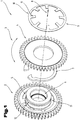
- Fig. 1 shows in exploded view a gear arrangement 1, as it is known from the prior art.
- This gear arrangement 1, also called “split gear”, has a main gear 2 and a relative to this relatively rotatable in a circumferential direction 3 gear 4, wherein the main gear 2 has a hub 5, which is in particular integrally formed with the main gear 2.
- the rotatable gear 4 is rotatably mounted on the hub 5 of the main gear 2.
- the hub 5 has a recess 6 in the form of a bore for receiving a shaft, not shown.
- the rotatable gear 4 is biased in the circumferential direction 3 relative to the main gear 2 by means of a spring element 7, which is in this case so-called ⁇ - spring, as shown in the WO 2005/090830 A1 is thus included in this scope of the basic structure of the gear assembly 1 to the content of this description.
- a spring element 7 is formed, which forms an assembly stop for another support web.
- the spring element 7 abuts against these support webs with its two open end regions.
- another spring element 9 which in this embodiment, the form of a plate spring, in particular a slotted plate spring to be designated in the broadest sense, arranged.
- This further spring element 9 has an outer ring 10, from which obliquely pointing radially inwards a plurality of tongues 11, so-called spring tongues, protrude. These tongues 11 are received by a circumferential groove 12, which is formed in an end portion 13 of the hub 5. By the spring tension is thus the further rotatable gear 4 in the axial direction biased against the main gear.
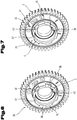
- the Fig. 2 to 7 show a first embodiment of the gear arrangement 1 according to the invention.
- Fig. 2 in turn, the main gear 2 and the adjacent thereto rotatable gear 4 can be seen.
- the rotatable gear 4 is arranged on the hub 5.
- This embodiment variant of the gear arrangement has, inter alia, the advantage that the additional spring element 9 of the embodiment according to Fig. 1 for axial securing of the rotatable gear 4 is not required.
- the biasing force for the rotatable gear 4 in the circumferential direction 3 by the spring element 7, for example, the ⁇ - spring, are generated.
- a bayonet 14 is arranged between the hub 5 of the main gear 2 and the rotatable gear 4.
- the rotatable gear 4 also has projections 16, which, however, extending radially inwardly in a recess 17 (FIG. Fig. 5 ) are arranged.
- the recess 17 is formed coaxially with the hub 5 and serves to be able to postpone the rotatable gear 4 to the hub 5 of the main gear 2.
- an inner diameter 18 between two opposing projections 16, as shown in FIG Fig. 5 is shown, a size which corresponds at least approximately to an outer diameter 19 of the hub in the region between recesses 20, wherein the recesses 20 are formed in the circumferential direction 3 between two adjacent hub projections 15 on the hub.
- the inner diameter 18 at least the outer diameter 19 corresponds in terms of its dimension, but preferably is slightly larger, so that the rotatable gear 4 can be easily pushed onto the hub 5.
- the recesses 20 between two hub projections 15 have a width 21 in the circumferential direction 3, which is at least as large as a width 22 (FIG. Fig. 5 ) of the projections 16 on the rotatable gear 4 in the same direction, so that the projections 16 can be inserted into these recesses 20.
- the width 21 is slightly greater than the width 22. It is further preferred if the recesses 20 in the axial direction of the gear arrangement 1 have a cross section which corresponds at least approximately to the cross section in the same direction of the projections 16 of the rotatable gear 4.
- an undercut 23 is formed in the form of a groove, as in particular from Fig. 4 can be seen.
- the hub projections 15 are thus spaced apart in the axial direction from an end face 24 (FIG. Fig. 7 ) of a gear body 25 of the main gear 2 - the main gear 2 consists of the gear body 25 and the hub 5 - arranged.
- a width 26 of the undercut 23 or the groove is chosen such that it has a size which is at least approximately a width 27 (FIG. Fig. 5 ) in the axial direction of the projections 16 of the rotatable gear 4, wherein at least approximately means that the width 26 of the undercut 23 is selected so that the rotatable gear 4 can be rotated in the circumferential direction 3.
- a facing in the direction of the gear body 25 of the main gear 2 end face 28 ( Fig. 3 ) of the hub projections 15 are aligned coplanar with the direction of the hub projections 15 facing end face 24 of the gear body 25 so that the undercut 23 in the circumferential direction 3 of the gear assembly has a rectangular or square cross-section.
- this end face 28 it is also possible for this end face 28 to be arranged at an oblique angle to the end face 24 of the gear body 25, so that the undercuts 23 narrow in the circumferential direction.
- a higher contact pressure of the rotatable gear 4 is achieved to the main gear 2 in a certain position, on the other hand, so that the rotatability of the rotatable gear 4 can be limited.
- the limitation of the rotatability of the rotatable gear 4 in the circumferential direction 3 of the gear assembly 1 can also be achieved so that the undercut 23 in the circumferential direction 3 is not continuous, so that the hub projections 15 are only partially spaced from the end face 24 of the gear body 25 of the main gear 2 ,
- the undercut 23 in the circumferential direction 3 is designed to be continuous, so that thus an annular groove is formed in the axial direction is open to the front in the region of the recesses 20.
- a groove bottom 29 ( Fig. 3 ) is preferably formed planar with a bottom surface 30 of the recesses 20.
- the groove bottom 29 is offset in the radial direction against this bottom surface, for example, is formed deeper, so as to form a "lubricant groove".
- the groove bottom 29 may be considered to be higher than the bottom surfaces 30 of the recesses 20 in the radial direction from the longitudinal central axis through the gear assembly 1, in which case the projections 16 of the rotatable gear 4 must be adjusted, ie a height 31 of the projections 16 in the radial direction is smaller than a height 32 of the hub projections 15, the difference resulting from the height difference in the radial direction between the groove bottom 29 and the bottom surface 30.
- the rotatable gear 4 is placed on the hub 5, wherein the projections 16 of the rotatable gear 4 are positioned in the axial direction in alignment with the recesses 20 of the hub 5, then the rotatable gear 4 in the axial direction in the direction pushed onto the gear body 25 of the main gear 2 and when the projections 16 of the rotatable gear 4 in the axial direction behind the hub projections 15 are circumferentially 3 rotated against the main gear, whereby on the projections 16 and the hub projections 15 of the bayonet lock 14 for axially securing the rotatable Gear 4 is made relative to the main gear 2.
- the spring element 7 can be arranged between the rotatable gear 4 and the main gear 2.
- a securing element 33 is pushed through the two gears, to which both the rotatable gear 4 and the Main gear 2 each have a recess 34 or 35 in the form of an opening. After installation of the gear arrangement 1, this securing element 33 is removed again.
- each six hub projections 15 and six projections 16 and accordingly six recesses 20 are shown, in the invention, a different number of hub projections 15, projections 16 and recesses 20 may be provided, for example, three, four, five, seven, eight, etc .. ..
- the hub projections 15 of the main gear 2 and the projections 16 of the rotatable gear 4 are arranged symmetrically about the circumference of the hub 5 and the recess 17 of the rotatable gear 4, that is between the distances between the hub projections 15 and projections 16 are equal are, as in the Fig. 2 to 5 is shown.
- the hub projections 15 in the direction of the circumference of the hub 5 have an overall length which is between 20%, in particular 40%, preferably 50%, and 80%, in particular 60%, of the length of the circumference of the hub 5 , In this case, the length of the circumference of the hub 5 in height of the bottom surface 30 of the recesses 20 - viewed in the radial direction - measured.
- At least transitions 36 between an axially forwardly facing end face 37 of the hub projections 15 and a peripheral surface 38 in the radially upper region of the hub projections 15 are rounded or chamfered.
- all transitions between the axially outwardly facing end face of the hub 5 and the circumferential surface of the hub 5 can be rounded or beveled, ie also the transitions in the area of the bottom surfaces 30 of the recesses 20 (it should be noted that the hub projections 15 are preferably in one piece formed with the hub, so that the peripheral surfaces 38 of the hub projections 15 form part of the total circumference of the hub 5).
- the main gear 2 is preferably made in one piece by a sintering process, that is, the hub 5 and the gear body 25 do not consist of two separate parts.
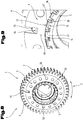
- a preform 39 as in Fig. 6 is prepared, for example, by the usual steps, such as optionally powder mixing, powder pressing in a mold, sintering, optionally after re-densification and / or calibration produced.
- this preform 39 differs from the finished gear only in that the undercut 23 or the (ring) groove between the thus not yet finished hub projections 15 and the gear body 25 is not yet formed, as the comparison of 6 and 7 shows.
- This undercut 23 is produced by the sintering process in a cutting process step with a tool, such as a chisel or by milling. Since the preform already has the recesses 20 between the hub projections 15 still to be finished, and recess end walls 40 of the recesses 20 are removed during the machining, the tool partially re-dips into the material of the hub 5 several times during the entire machining process. Thus, a higher tool wear and an increased burr formation are connected by the interrupted cut in the processing zone.
- a tool such as a chisel or by milling.
- the hub projections 15 at least partially have a trapezoidal cross-section when viewed in the axial direction.
- the cross section of the hub projections 15 can also be composed of several geometric shapes, for example, the cross section consists of a rectangle with attached trapezoid.
- a second side wall 42 of the recesses 20 and the hub projections 15, which is formed in the circumferential direction on the first side wall 41 following, against the bottom surface 30th is inclined, with an angle greater than 90 °.
- Embodiments of the cross-section which are symmetrical, that is, the two at least partially inclined side surfaces 41, 42 include the same angular value with the bottom surface 30, so that the cross section of the hub projections 15 at least partially, preferably entirely, has an isosceles trapezoid in the axial direction ,
- the angle which at least one of the side surfaces 41, 42 encloses with the bottom surface 30 is preferably selected from a range with a lower limit of 95 °, in particular 100 °, and an upper limit of 130 °, in particular 120 °.
- the projections 16 of the rotatable gear 4 have a cross section, which follow the contour of the recesses 30 of the hub 5, although this is the preferred embodiment of the gear assembly 1.
- an annular web 45 is formed, via which the rotatable gear 2 rests on the gear body 25 of the main gear 2, as in Fig. 4 is shown.
- a recess 46 in the form of an annular groove for receiving the spring element 7 between the rotatable gear 4 and the main gear 2 are created.
- This recess 46 can also be created at least partially by a corresponding indentation in the gear body 25 of the main gear 2.
- this ring land 45 can also be arranged on the gear body 25 of the main gear 2, or there is the possibility that both the rotatable gear 4 and the main gear 2 have such a ring land 45.
- annular groove for receiving the annular web 45 is arranged in order to achieve better guidance of the rotatable gear 4 on the main gear 2 during rotation.
- the rotatable gear 4 is recessed in a region 47 of the abutment of the projections 16 on the hub projections 15, so that the projections 16 are not in one plane with a main body 48 of the rotatable gear 4 above the region 47, as in Fig. 5 is shown in order to improve the training of the banjo zipper between the two gears.
- the 8 and 9 show a non-inventive embodiment of the gear assembly 1 in an oblique view or detail view with the main gear 2, the adjacent thereto rotatable gear 4 and the spring element 9, in particular a plate spring.
- the bayonet closure 14 is formed in this embodiment of the gear arrangement 1 between the hub 5 and serving as an axial securing spring element 9.
- the hub 5 in turn on the radially outwardly projecting hub projections 15.
- the projections 16 are also provided, which are however arranged unlike the above embodiment on the spring element 9 and are arranged by a spring element body 49 projecting radially inwardly in a recess 50 of the spring element 9.
- the recess 50 is sized, i. its diameter, so dimensioned that the spring element 9 can be pushed onto the hub 5, to which the projections 16 on the spring element 9, as in the above embodiment, the projections 16 are pushed through the recesses 20 between the hub projections 15.
- no annular groove for receiving the projections 16 of the spring element 9 is formed behind the hub projections 15, but the top walls 43 and top surfaces are angled, so so - viewed in the circumferential direction 3 of the gear assembly 1 - the hub projections in Area of the cover walls 43 have an at least approximately triangular cross-section.
- an edge-like center elevation 51 is dimensioned such that a circle following the center elevations of all hub projections 15 has a diameter 52 which is greater than a smallest inner diameter of the spring element 9, which is defined by the end regions of the tongue-shaped projections 16 of the spring element 9.
- the diameter defined by the hub projections 15 becomes smaller again - in comparison to the diameter defined by the edge-shaped center elevations 51 - so that the projections 16 of the spring element can be pushed onto the cover walls 43 of the hub projections 15 like this in Fig. 9 shown in detail.
- the center elevations 51 of the hub projections 15 do not necessarily have to be edge-shaped.
- these center elevations 51 can also be flattened, resulting in a step-shaped course in the area of the cover walls 43 with regard to the cross section of the hub projections 15.
- the center elevations 15 extend as far as an outer end face 53 of the hub projections 15.
- the spring element 9 is provided with an anti-rotation 54, which is designed in the illustrated embodiment as a tab which is bent in the direction of the rotatable gear 4 and is received in a recess 55 of the rotatable gear 4.
- an anti-rotation 54 which is designed in the illustrated embodiment as a tab which is bent in the direction of the rotatable gear 4 and is received in a recess 55 of the rotatable gear 4.
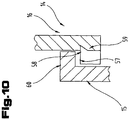
- Fig. 10 shows a variant of a bayonet closure 14.
- the hub projections 15 and the projections 16 of the rotatable gear 4 (not shown) in cross-section - in the circumferential direction 3 (eg Fig. 8 ) - each provided with an undercut 57, 58, so that the hub projections 15 and the projections 16 of the rotatable gear 4 are angular and engage bends 59 of the projections 16 of the rotatable gear 4 below bends 60 of the hub projections 15.
- the bends 59, 60 thereby run at least approximately in the axial direction of the gear arrangement 1.
- the main gear 2 and the rotatable gear 4 are preferably made of a sintered steel
- the further spring element 9 consists of a spring steel
Landscapes
- Engineering & Computer Science (AREA)
- General Engineering & Computer Science (AREA)
- Mechanical Engineering (AREA)
- Manufacturing & Machinery (AREA)
- Gears, Cams (AREA)
Claims (10)
- Agencement de roues dentées (1) comprenant une roue dentée principale (2) et une roue dentée (4) déplaçable en rotation en direction circonférentielle (3) par rapport à la première, la roue dentée principale (2) ayant un corps de roue dentée (25) sur lequel est disposé un moyeu (5) en saillie servant d'une part à recevoir un axe et d'autre part à disposer la roue dentée (4) déplaçable en rotation, la roue dentée (4) déplaçable en rotation présentant un évidement (17) coaxial à un axe central s'étendant axialement de la roue dentée principale (2), et la roue dentée principale (2) étant reliée à la roue dentée (4) déplaçable en rotation par un emboîtement à baïonnette (14) qui est formé entre le moyeu (5) et la roue dentée (4) déplaçable en rotation, des saillies de moyeu (15) s'étendant radialement vers l'extérieur étant disposées sur le moyeu (5) et une contre-dépouille (23) sous la forme d'une rainure s'étendant dans la direction du pourtour du moyeu (5) étant formée en direction axiale entre les saillies de moyeu (15) et le corps de roue dentée (25), des saillies (16) s'étendant radialement vers l'intérieur étant formées dans l'évidement (17) de la roue dentée (4) déplaçable en rotation, et un diamètre intérieur (18) entre deux saillies (16) en regard présentant une dimension qui correspond au moins approximativement à un diamètre extérieur (19) du moyeu (5) aux alentours d'évidements (20) qui sont formés sur le moyeu (5) en direction périphérique (3) entre deux saillies de moyeu (15) avoisinantes, un verrouillage axial étant formé, par l'emboîtement à baïonnette, pour la roue dentée déplaçable en rotation et, par cela, la position relative de la roue dentée (4) déplaçable en rotation est fixée en direction axiale de l'agencement de roues dentées (1), une largeur (26) de la contre-dépouille (23) présentant une dimension qui correspond au moins approximativement à une largeur (27) des saillies (16) de la roue dentée (4) déplaçable en rotation, caractérisé en ce que les saillies de moyeu (15) présentent, vu en direction axiale, au moins partiellement une section transversale en forme de trapèze.
- Agencement de roues dentées (1) selon la revendication 1, caractérisé en ce que les saillies de moyeu (15) sont disposées en répartition symétrique sur le pourtour du moyeu (5).
- Agencement de roues dentées (1) selon la revendication 1 ou 2, caractérisé en ce que la contre-dépouille (25) s'étend de manière continue sur le pourtour du moyeu (5).
- Agencement de roues dentées (1) selon l'une des revendications 1 à 3, caractérisé en ce que les saillies de moyeu (15) présentent, en direction périphérique (3) du moyeu (5), une longueur totale d'entre 20% et 80% de la longueur du pourtour du moyeu (5).
- Agencement de roues dentées (1) selon l'une quelconque des revendications 1 à 5, caractérisé en ce qu'une transition entre une face frontale du moyeu (5) et la surface de pourtour (38) aux alentours des saillies de moyeu (15) est formée de façon arrondie ou chanfreinée.
- Procédé de fabrication d'un emboîtement à baïonnette (14) pour un agencement de roues dentées (1) comprenant une roue dentée principale (2) et une roue dentée (4) déplaçable en rotation en direction circonférentielle (3) par rapport à la première selon l'une quelconque des revendications 1 à 6, la roue dentée principale (2) ayant un corps de roue dentée (25) sur lequel est disposé un moyeu (5) en saillie servant d'une part à recevoir un axe et d'autre part à disposer la roue dentée (4) déplaçable en rotation, ce pourquoi la roue dentée (4) déplaçable en rotation présentant un évidement (17) coaxial à un axe central s'étendant radialement de la roue dentée principale (2), caractérisé en ce que celui-ci comprend les étapes de- fabrication par frittage d'une ébauche (39) en une seule pièce pour la roue dentée principale (2) avec le corps de roue dentée (25) et le moyeu (5), des évidements (20) étant formés sur le pourtour du moyeu (5), en commençant à une face frontale du moyeu (5), qui s'étendent en direction axiale sur le corps de roue dentée (25) et qui s'étendent jusqu'à une paroi de fond d'évidement (40) située en direction axiale en regard de la face frontale du moyeu (5), et qui présentent chacun deux parois latérales (41, 42) et une surface de fond (30), au moins une des parois latérales (41, 42) enfermant avec la surface de fond (30) de l'évidement (20) un angle qui est supérieur à 90°,- usinage avec formation de copeaux du moyeu (5) en direction périphérique (3), les parois de fond (40) des évidements étant enlevées et des contre-dépouilles (23) étant formées partiellement, ce par quoi des saillies de moyeu (15) étant formées qui constituent une partie de l'emboîtement à baïonnette (14).
- Procédé selon la revendication 6, caractérisé en ce que l'angle entre lesdites au moins unes parois latérales (41, 42) et les surfaces de fond (30) est choisi dans une plage ayant une limite inférieure de 95° et une limite supérieure de 130°.
- Procédé selon la revendication 6 ou 7, caractérisé en ce que au moins quelques bords, de préférence tous les bords, des évidements (20) sont formés de façon arrondie ou chanfreinée.
- Procédé selon l'une quelconque des revendications 6 à 8, caractérisé en ce que la roue dentée (4) déplaçable en rotation est également réalisée par frittage, des saillies (16) s'étendant radialement vers l'intérieur étant formées dans l'évidement (17) de la roue dentée (2).
- Procédé selon la revendication 9, caractérisé en ce qu'un pont annulaire (45) est formé sur une face frontale (44), s'étendant en direction radiale, de la roue dentée (4) déplaçable en rotation.
Applications Claiming Priority (2)
| Application Number | Priority Date | Filing Date | Title |
|---|---|---|---|
| AT0162510A AT510283B1 (de) | 2010-09-29 | 2010-09-29 | Zahnradanordnung |
| PCT/AT2011/050014 WO2012040762A1 (fr) | 2010-09-29 | 2011-09-27 | Ensemble de roues dentées et procédé de production d'une fermeture à baïonnette |
Publications (3)
| Publication Number | Publication Date |
|---|---|
| EP2622244A1 EP2622244A1 (fr) | 2013-08-07 |
| EP2622244B1 EP2622244B1 (fr) | 2016-05-11 |
| EP2622244B2 true EP2622244B2 (fr) | 2018-11-07 |
Family
ID=45509161
Family Applications (1)
| Application Number | Title | Priority Date | Filing Date |
|---|---|---|---|
| EP11810994.1A Active EP2622244B2 (fr) | 2010-09-29 | 2011-09-27 | Agencement de roue dentée et procédé de fabrication d'un emboîtement à baïonnette |
Country Status (6)
| Country | Link |
|---|---|
| US (1) | US9297451B2 (fr) |
| EP (1) | EP2622244B2 (fr) |
| CN (1) | CN103124867B (fr) |
| AT (1) | AT510283B1 (fr) |
| BR (1) | BR112013007526A2 (fr) |
| WO (1) | WO2012040762A1 (fr) |
Families Citing this family (24)
| Publication number | Priority date | Publication date | Assignee | Title |
|---|---|---|---|---|
| AT510283B1 (de) | 2010-09-29 | 2012-03-15 | Miba Sinter Austria Gmbh | Zahnradanordnung |
| DE102011122138A1 (de) * | 2011-12-22 | 2013-06-27 | PMG Füssen GmbH | Zahnradanordnung |
| CN102829157A (zh) * | 2012-09-11 | 2012-12-19 | 力帆实业(集团)股份有限公司 | 发动机排气正时齿轮 |
| DE102012025210B4 (de) * | 2012-12-28 | 2014-08-14 | Gkn Sinter Metals Holding Gmbh | Geteiltes Zahnrad |
| AT513613B1 (de) * | 2013-02-08 | 2014-06-15 | Miba Sinter Austria Gmbh | Zahnradanordnung |
| DE102013009751A1 (de) * | 2013-06-11 | 2014-12-11 | Daimler Ag | Stirnrad für einen Ventiltrieb |
| AT514070B1 (de) * | 2013-06-11 | 2014-10-15 | Miba Sinter Austria Gmbh | Zahnradanordnung |
| US9618108B2 (en) * | 2013-07-17 | 2017-04-11 | Achates Power, Inc. | Gear noise reduction in opposed-piston engines |
| US9772030B2 (en) * | 2014-08-04 | 2017-09-26 | Achates Power, Inc. | Split gear assembly with one-way roller clutch for controlling backlash in opposed-piston engines |
| EP3230626B1 (fr) * | 2014-12-11 | 2020-08-19 | Linamar Corporation | Ensemble engrenage en ciseaux doté d'un mécanisme d'isolation intégré |
| DE102015004454A1 (de) | 2015-04-04 | 2016-10-06 | Daimler Ag | Tellerfeder, insbesondere für einen Antriebsstrang eines Kraftwagens, sowie Antriebsstrang und Verfahren zum Montieren einer solchen Tellerfeder |
| NL2015189B1 (en) * | 2015-07-18 | 2017-02-07 | Vcst Ind Products Bvba | Scissor gear assembly. |
| AT518787B1 (de) | 2016-07-18 | 2018-01-15 | Miba Sinter Austria Gmbh | Zahnradanordnung |
| AT519135B1 (de) * | 2016-09-22 | 2019-03-15 | Miba Sinter Austria Gmbh | Verfahren zur Herstellung eines Stators für einen Nockenwellenversteller |
| FR3060072B1 (fr) * | 2016-12-12 | 2020-06-26 | Peugeot Citroen Automobiles Sa | Element mecanique circulaire de transmission de mouvement |
| DE102016226131B4 (de) * | 2016-12-23 | 2024-05-16 | Robert Bosch Gmbh | Antriebsrad für eine Getriebe-Antriebseinrichtung und Getriebe-Antriebseinrichtung |
| DE102017217397A1 (de) * | 2017-09-29 | 2019-04-04 | Aktiebolaget Skf | Lageranordnung, die mit einem Wälzlager und einem Scherenzahnrad ausgestattet ist, insbesondere für eine Ausgleichswelle |
| DE102017126205A1 (de) * | 2017-11-09 | 2019-05-09 | Man Truck & Bus Ag | Zahnrad, insbesondere Zwischenrad, für einen Rädertrieb |
| AT520531B1 (de) * | 2018-04-24 | 2019-05-15 | Miba Sinter Austria Gmbh | Zahnrad |
| DE102018207493A1 (de) * | 2018-05-15 | 2019-11-21 | Sram Deutschland Gmbh | Stelleinrichtung für ein Fahrrad und Verfahren zur Steuerung oder Einstellung solcher Stelleinrichtungen |
| AT521375B1 (de) * | 2018-11-15 | 2020-01-15 | Miba Sinter Austria Gmbh | Zahnradanordnung |
| CN109751394B (zh) * | 2019-02-28 | 2021-09-03 | 西安工业大学 | 一种可更换式动力分流传动组合齿轮 |
| US12049947B2 (en) | 2021-07-23 | 2024-07-30 | Gates Corporation | Segmented sprocket systems and methods for installing the same |
| CN113565944B (zh) * | 2021-07-28 | 2023-07-28 | 中山市技佳传动科技有限公司 | 一种高强度塑料齿轮及其制备工艺 |
Family Cites Families (26)
| Publication number | Priority date | Publication date | Assignee | Title |
|---|---|---|---|---|
| US1554889A (en) | 1924-08-01 | 1925-09-22 | William A Hutson | Antirattling gear |
| US4189951A (en) * | 1978-06-27 | 1980-02-26 | Bulova Watch Company, Inc. | Anti-backlash gear |
| US4273995A (en) * | 1979-12-10 | 1981-06-16 | Veeder Industries Inc. | Fuel pump counter transfer pinion |
| JPS611770U (ja) * | 1984-06-12 | 1986-01-08 | トヨタ自動車株式会社 | 無背隙歯車装置 |
| JPH0141972Y2 (fr) * | 1985-06-12 | 1989-12-11 | ||
| US5113713A (en) * | 1991-02-11 | 1992-05-19 | United Technologies Corporation | Elastomeric load sharing device |
| DE59404267D1 (de) * | 1993-09-08 | 1997-11-13 | Erowa Ag | Drehantriebsvorrichtung |
| DE9415460U1 (de) * | 1994-09-23 | 1995-07-20 | Siemens AG, 80333 München | Getriebeantrieb, insbesondere Schneckengetriebe |
| JPH08159242A (ja) | 1994-12-02 | 1996-06-21 | Victor Co Of Japan Ltd | バックラッシュレス歯車構造 |
| GB2305990B (en) * | 1995-10-03 | 1999-05-26 | Perkins Ltd | A method and a device for setting backlash between gears in a gear train |
| US5934144A (en) * | 1996-06-10 | 1999-08-10 | Active Automation, Inc. | Split gear assembly for use in a worm gear drive |
| US5813335A (en) * | 1996-12-18 | 1998-09-29 | Heidelberg Harris Inc. | Apparatus for preventing backlash between the meshing teeth of a first and a second gear in a printing unit of a lithographic rotary printing press |
| US5870928A (en) * | 1997-05-08 | 1999-02-16 | Cummins Engine Company, Inc. | Anti-lash gear with alignment device |
| US6148684A (en) * | 1999-03-10 | 2000-11-21 | Heidelberger Druckmaschinen Aktiengesellschaft | Anti-backlash gear |
| GB2360825B (en) * | 2000-03-30 | 2004-11-17 | Formflo Ltd | Gear wheels roll formed from powder metal blanks |
| IT250014Y1 (it) * | 2000-07-03 | 2003-07-07 | Re M S R L | Struttura di ruota dentata |
| JP3658369B2 (ja) * | 2001-10-10 | 2005-06-08 | キヤノン株式会社 | 画像形成装置 |
| AT413748B (de) | 2004-03-22 | 2006-05-15 | Miba Sinter Austria Gmbh | Zahnrad für eine spielfreie stirnradstufe |
| JP4053528B2 (ja) | 2004-09-07 | 2008-02-27 | 本田技研工業株式会社 | シザーズギヤ |
| DE102005041357A1 (de) * | 2004-09-07 | 2006-04-06 | Honda Motor Co., Ltd. | Scherzahnrad und spielfreier Mechanismus |
| WO2008142131A2 (fr) | 2007-05-21 | 2008-11-27 | Vcst Industrial Products | Engrenage en deux pièces pour éviter un jeu d'engrènement lors de l'engagement avec un engrenage correspondant |
| EP2146116A4 (fr) | 2008-03-28 | 2011-05-04 | Nec Display Solutions Ltd | Engrenage combine, mecanisme d'ajustement de lentille et equipement electronique |
| AT506961B1 (de) | 2008-09-09 | 2010-01-15 | Miba Sinter Austria Gmbh | Zahnradanordnung |
| KR101047607B1 (ko) * | 2008-12-05 | 2011-07-07 | 현대자동차주식회사 | 시저스 기어 |
| DE102009015953B4 (de) | 2009-03-27 | 2012-09-20 | Getrag Getriebe- Und Zahnradfabrik Hermann Hagenmeyer Gmbh & Co. Kg | Rasselfreie Bauteilpaarung |
| AT510283B1 (de) | 2010-09-29 | 2012-03-15 | Miba Sinter Austria Gmbh | Zahnradanordnung |
-
2010
- 2010-09-29 AT AT0162510A patent/AT510283B1/de not_active IP Right Cessation
-
2011
- 2011-09-27 EP EP11810994.1A patent/EP2622244B2/fr active Active
- 2011-09-27 WO PCT/AT2011/050014 patent/WO2012040762A1/fr active Application Filing
- 2011-09-27 BR BR112013007526A patent/BR112013007526A2/pt not_active IP Right Cessation
- 2011-09-27 US US13/823,898 patent/US9297451B2/en not_active Expired - Fee Related
- 2011-09-27 CN CN201180044798.4A patent/CN103124867B/zh not_active Expired - Fee Related
Also Published As
| Publication number | Publication date |
|---|---|
| US9297451B2 (en) | 2016-03-29 |
| BR112013007526A2 (pt) | 2016-07-19 |
| AT510283A4 (de) | 2012-03-15 |
| CN103124867B (zh) | 2016-05-25 |
| EP2622244B1 (fr) | 2016-05-11 |
| EP2622244A1 (fr) | 2013-08-07 |
| AT510283B1 (de) | 2012-03-15 |
| CN103124867A (zh) | 2013-05-29 |
| US20130213168A1 (en) | 2013-08-22 |
| WO2012040762A1 (fr) | 2012-04-05 |
Similar Documents
| Publication | Publication Date | Title |
|---|---|---|
| EP2622244B2 (fr) | Agencement de roue dentée et procédé de fabrication d'un emboîtement à baïonnette | |
| EP0717212B1 (fr) | Synchronisateur de boíte de vitesse | |
| EP1834102B1 (fr) | Liaison arbre-moyeu a systeme d'arret | |
| AT513613B1 (de) | Zahnradanordnung | |
| AT393717B (de) | Verzahnung zur loes- und verschiebbaren verbindung sowie drehmomentuebertragung zwischen zwei koaxial ineinander angeordneten bauteilen | |
| WO2012037593A2 (fr) | Engrenage | |
| EP1272305A1 (fr) | Plaquette de coupe de fraise pour arbres a cames | |
| EP2161478B1 (fr) | Agencement de roue dentée | |
| AT511596B1 (de) | Synchronkörper | |
| EP3409392A1 (fr) | Procédé de fabrication de pièces estampées | |
| EP2766572A2 (fr) | Porte-outil | |
| EP2435721A1 (fr) | Liaison arbre-moyeu à profil polygonal | |
| EP2179191B1 (fr) | Élément d'accouplement pour un accouplement entraîneur, et procédé de fabrication | |
| EP3974680B1 (fr) | Roue à composants multiples, pignon et train épicycloïdal | |
| EP0906520A1 (fr) | Denture d'accouplement dans une boite de vitesses | |
| AT517814A2 (de) | Verfahren zur Herstellung einer Stahl- Reiblamelle für eine Reibungskupplung | |
| EP2769109A1 (fr) | Dispositif d'assemblage et procédé de fabrication dudit dispositif | |
| EP2483027A1 (fr) | Procédé de fabrication d'une denture intérieure et élément à denture intérieure | |
| DE102017107209B4 (de) | Reiblamelle aus mehreren miteinander verbundenen Segmenten | |
| EP3835609B1 (fr) | Dispositif de synchronisation | |
| EP4415976A1 (fr) | Denture faciale à rayons de mise en forme | |
| WO2022127965A1 (fr) | Système de denture droite pour agencement de roulement de roue | |
| DE10021588B4 (de) | Kupplungsverzahnung eines Elementes einer Synchronisiereinheit | |
| DE102020130712A1 (de) | Synchronring für ein Schaltgetriebe | |
| AT521391A1 (de) | Schiebemuffe |
Legal Events
| Date | Code | Title | Description |
|---|---|---|---|
| PUAI | Public reference made under article 153(3) epc to a published international application that has entered the european phase |
Free format text: ORIGINAL CODE: 0009012 |
|
| 17P | Request for examination filed |
Effective date: 20130426 |
|
| AK | Designated contracting states |
Kind code of ref document: A1 Designated state(s): AL AT BE BG CH CY CZ DE DK EE ES FI FR GB GR HR HU IE IS IT LI LT LU LV MC MK MT NL NO PL PT RO RS SE SI SK SM TR |
|
| DAX | Request for extension of the european patent (deleted) | ||
| 17Q | First examination report despatched |
Effective date: 20141105 |
|
| GRAP | Despatch of communication of intention to grant a patent |
Free format text: ORIGINAL CODE: EPIDOSNIGR1 |
|
| INTG | Intention to grant announced |
Effective date: 20151202 |
|
| GRAS | Grant fee paid |
Free format text: ORIGINAL CODE: EPIDOSNIGR3 |
|
| GRAA | (expected) grant |
Free format text: ORIGINAL CODE: 0009210 |
|
| AK | Designated contracting states |
Kind code of ref document: B1 Designated state(s): AL AT BE BG CH CY CZ DE DK EE ES FI FR GB GR HR HU IE IS IT LI LT LU LV MC MK MT NL NO PL PT RO RS SE SI SK SM TR |
|
| REG | Reference to a national code |
Ref country code: GB Ref legal event code: FG4D Free format text: NOT ENGLISH |
|
| REG | Reference to a national code |
Ref country code: CH Ref legal event code: EP |
|
| REG | Reference to a national code |
Ref country code: AT Ref legal event code: REF Ref document number: 798927 Country of ref document: AT Kind code of ref document: T Effective date: 20160515 |
|
| REG | Reference to a national code |
Ref country code: IE Ref legal event code: FG4D Free format text: LANGUAGE OF EP DOCUMENT: GERMAN |
|
| REG | Reference to a national code |
Ref country code: DE Ref legal event code: R096 Ref document number: 502011009761 Country of ref document: DE |
|
| REG | Reference to a national code |
Ref country code: LT Ref legal event code: MG4D |
|
| REG | Reference to a national code |
Ref country code: NL Ref legal event code: MP Effective date: 20160511 |
|
| PG25 | Lapsed in a contracting state [announced via postgrant information from national office to epo] |
Ref country code: FI Free format text: LAPSE BECAUSE OF FAILURE TO SUBMIT A TRANSLATION OF THE DESCRIPTION OR TO PAY THE FEE WITHIN THE PRESCRIBED TIME-LIMIT Effective date: 20160511 Ref country code: NL Free format text: LAPSE BECAUSE OF FAILURE TO SUBMIT A TRANSLATION OF THE DESCRIPTION OR TO PAY THE FEE WITHIN THE PRESCRIBED TIME-LIMIT Effective date: 20160511 Ref country code: LT Free format text: LAPSE BECAUSE OF FAILURE TO SUBMIT A TRANSLATION OF THE DESCRIPTION OR TO PAY THE FEE WITHIN THE PRESCRIBED TIME-LIMIT Effective date: 20160511 Ref country code: NO Free format text: LAPSE BECAUSE OF FAILURE TO SUBMIT A TRANSLATION OF THE DESCRIPTION OR TO PAY THE FEE WITHIN THE PRESCRIBED TIME-LIMIT Effective date: 20160811 |
|
| PG25 | Lapsed in a contracting state [announced via postgrant information from national office to epo] |
Ref country code: PT Free format text: LAPSE BECAUSE OF FAILURE TO SUBMIT A TRANSLATION OF THE DESCRIPTION OR TO PAY THE FEE WITHIN THE PRESCRIBED TIME-LIMIT Effective date: 20160912 Ref country code: SE Free format text: LAPSE BECAUSE OF FAILURE TO SUBMIT A TRANSLATION OF THE DESCRIPTION OR TO PAY THE FEE WITHIN THE PRESCRIBED TIME-LIMIT Effective date: 20160511 Ref country code: ES Free format text: LAPSE BECAUSE OF FAILURE TO SUBMIT A TRANSLATION OF THE DESCRIPTION OR TO PAY THE FEE WITHIN THE PRESCRIBED TIME-LIMIT Effective date: 20160511 Ref country code: LV Free format text: LAPSE BECAUSE OF FAILURE TO SUBMIT A TRANSLATION OF THE DESCRIPTION OR TO PAY THE FEE WITHIN THE PRESCRIBED TIME-LIMIT Effective date: 20160511 Ref country code: HR Free format text: LAPSE BECAUSE OF FAILURE TO SUBMIT A TRANSLATION OF THE DESCRIPTION OR TO PAY THE FEE WITHIN THE PRESCRIBED TIME-LIMIT Effective date: 20160511 Ref country code: RS Free format text: LAPSE BECAUSE OF FAILURE TO SUBMIT A TRANSLATION OF THE DESCRIPTION OR TO PAY THE FEE WITHIN THE PRESCRIBED TIME-LIMIT Effective date: 20160511 Ref country code: GR Free format text: LAPSE BECAUSE OF FAILURE TO SUBMIT A TRANSLATION OF THE DESCRIPTION OR TO PAY THE FEE WITHIN THE PRESCRIBED TIME-LIMIT Effective date: 20160812 |
|
| PG25 | Lapsed in a contracting state [announced via postgrant information from national office to epo] |
Ref country code: IT Free format text: LAPSE BECAUSE OF FAILURE TO SUBMIT A TRANSLATION OF THE DESCRIPTION OR TO PAY THE FEE WITHIN THE PRESCRIBED TIME-LIMIT Effective date: 20160511 |
|
| PG25 | Lapsed in a contracting state [announced via postgrant information from national office to epo] |
Ref country code: CZ Free format text: LAPSE BECAUSE OF FAILURE TO SUBMIT A TRANSLATION OF THE DESCRIPTION OR TO PAY THE FEE WITHIN THE PRESCRIBED TIME-LIMIT Effective date: 20160511 Ref country code: EE Free format text: LAPSE BECAUSE OF FAILURE TO SUBMIT A TRANSLATION OF THE DESCRIPTION OR TO PAY THE FEE WITHIN THE PRESCRIBED TIME-LIMIT Effective date: 20160511 Ref country code: RO Free format text: LAPSE BECAUSE OF FAILURE TO SUBMIT A TRANSLATION OF THE DESCRIPTION OR TO PAY THE FEE WITHIN THE PRESCRIBED TIME-LIMIT Effective date: 20160511 Ref country code: SK Free format text: LAPSE BECAUSE OF FAILURE TO SUBMIT A TRANSLATION OF THE DESCRIPTION OR TO PAY THE FEE WITHIN THE PRESCRIBED TIME-LIMIT Effective date: 20160511 Ref country code: DK Free format text: LAPSE BECAUSE OF FAILURE TO SUBMIT A TRANSLATION OF THE DESCRIPTION OR TO PAY THE FEE WITHIN THE PRESCRIBED TIME-LIMIT Effective date: 20160511 |
|
| REG | Reference to a national code |
Ref country code: DE Ref legal event code: R026 Ref document number: 502011009761 Country of ref document: DE |
|
| PLBI | Opposition filed |
Free format text: ORIGINAL CODE: 0009260 |
|
| PG25 | Lapsed in a contracting state [announced via postgrant information from national office to epo] |
Ref country code: SM Free format text: LAPSE BECAUSE OF FAILURE TO SUBMIT A TRANSLATION OF THE DESCRIPTION OR TO PAY THE FEE WITHIN THE PRESCRIBED TIME-LIMIT Effective date: 20160511 Ref country code: PL Free format text: LAPSE BECAUSE OF FAILURE TO SUBMIT A TRANSLATION OF THE DESCRIPTION OR TO PAY THE FEE WITHIN THE PRESCRIBED TIME-LIMIT Effective date: 20160511 Ref country code: BE Free format text: LAPSE BECAUSE OF NON-PAYMENT OF DUE FEES Effective date: 20160930 |
|
| PLAX | Notice of opposition and request to file observation + time limit sent |
Free format text: ORIGINAL CODE: EPIDOSNOBS2 |
|
| 26 | Opposition filed |
Opponent name: SCHWAEBISCHE HUETTENWERKE AUTOMOTIVE GMBH Effective date: 20170209 |
|
| PG25 | Lapsed in a contracting state [announced via postgrant information from national office to epo] |
Ref country code: MC Free format text: LAPSE BECAUSE OF FAILURE TO SUBMIT A TRANSLATION OF THE DESCRIPTION OR TO PAY THE FEE WITHIN THE PRESCRIBED TIME-LIMIT Effective date: 20160511 |
|
| REG | Reference to a national code |
Ref country code: CH Ref legal event code: PL |
|
| PLBB | Reply of patent proprietor to notice(s) of opposition received |
Free format text: ORIGINAL CODE: EPIDOSNOBS3 |
|
| GBPC | Gb: european patent ceased through non-payment of renewal fee |
Effective date: 20160927 |
|
| PG25 | Lapsed in a contracting state [announced via postgrant information from national office to epo] |
Ref country code: SI Free format text: LAPSE BECAUSE OF FAILURE TO SUBMIT A TRANSLATION OF THE DESCRIPTION OR TO PAY THE FEE WITHIN THE PRESCRIBED TIME-LIMIT Effective date: 20160511 |
|
| REG | Reference to a national code |
Ref country code: IE Ref legal event code: MM4A |
|
| REG | Reference to a national code |
Ref country code: FR Ref legal event code: ST Effective date: 20170531 |
|
| PG25 | Lapsed in a contracting state [announced via postgrant information from national office to epo] |
Ref country code: FR Free format text: LAPSE BECAUSE OF NON-PAYMENT OF DUE FEES Effective date: 20160930 Ref country code: GB Free format text: LAPSE BECAUSE OF NON-PAYMENT OF DUE FEES Effective date: 20160927 Ref country code: CH Free format text: LAPSE BECAUSE OF NON-PAYMENT OF DUE FEES Effective date: 20160930 Ref country code: IE Free format text: LAPSE BECAUSE OF NON-PAYMENT OF DUE FEES Effective date: 20160927 Ref country code: LI Free format text: LAPSE BECAUSE OF NON-PAYMENT OF DUE FEES Effective date: 20160930 |
|
| PG25 | Lapsed in a contracting state [announced via postgrant information from national office to epo] |
Ref country code: LU Free format text: LAPSE BECAUSE OF NON-PAYMENT OF DUE FEES Effective date: 20160927 |
|
| PLBP | Opposition withdrawn |
Free format text: ORIGINAL CODE: 0009264 |
|
| REG | Reference to a national code |
Ref country code: AT Ref legal event code: MM01 Ref document number: 798927 Country of ref document: AT Kind code of ref document: T Effective date: 20160927 |
|
| REG | Reference to a national code |
Ref country code: BE Ref legal event code: MM Effective date: 20160930 |
|
| PG25 | Lapsed in a contracting state [announced via postgrant information from national office to epo] |
Ref country code: AT Free format text: LAPSE BECAUSE OF NON-PAYMENT OF DUE FEES Effective date: 20160927 |
|
| PG25 | Lapsed in a contracting state [announced via postgrant information from national office to epo] |
Ref country code: HU Free format text: LAPSE BECAUSE OF FAILURE TO SUBMIT A TRANSLATION OF THE DESCRIPTION OR TO PAY THE FEE WITHIN THE PRESCRIBED TIME-LIMIT; INVALID AB INITIO Effective date: 20110927 Ref country code: CY Free format text: LAPSE BECAUSE OF FAILURE TO SUBMIT A TRANSLATION OF THE DESCRIPTION OR TO PAY THE FEE WITHIN THE PRESCRIBED TIME-LIMIT Effective date: 20160511 |
|
| PG25 | Lapsed in a contracting state [announced via postgrant information from national office to epo] |
Ref country code: MT Free format text: LAPSE BECAUSE OF FAILURE TO SUBMIT A TRANSLATION OF THE DESCRIPTION OR TO PAY THE FEE WITHIN THE PRESCRIBED TIME-LIMIT Effective date: 20160511 Ref country code: TR Free format text: LAPSE BECAUSE OF FAILURE TO SUBMIT A TRANSLATION OF THE DESCRIPTION OR TO PAY THE FEE WITHIN THE PRESCRIBED TIME-LIMIT Effective date: 20160511 Ref country code: MK Free format text: LAPSE BECAUSE OF FAILURE TO SUBMIT A TRANSLATION OF THE DESCRIPTION OR TO PAY THE FEE WITHIN THE PRESCRIBED TIME-LIMIT Effective date: 20160511 Ref country code: IS Free format text: LAPSE BECAUSE OF FAILURE TO SUBMIT A TRANSLATION OF THE DESCRIPTION OR TO PAY THE FEE WITHIN THE PRESCRIBED TIME-LIMIT Effective date: 20160511 |
|
| REG | Reference to a national code |
Ref country code: DE Ref legal event code: R082 Ref document number: 502011009761 Country of ref document: DE Representative=s name: ABP BURGER RECHTSANWALTSGESELLSCHAFT MBH, DE |
|
| PG25 | Lapsed in a contracting state [announced via postgrant information from national office to epo] |
Ref country code: BG Free format text: LAPSE BECAUSE OF FAILURE TO SUBMIT A TRANSLATION OF THE DESCRIPTION OR TO PAY THE FEE WITHIN THE PRESCRIBED TIME-LIMIT Effective date: 20160511 |
|
| PUAH | Patent maintained in amended form |
Free format text: ORIGINAL CODE: 0009272 |
|
| STAA | Information on the status of an ep patent application or granted ep patent |
Free format text: STATUS: PATENT MAINTAINED AS AMENDED |
|
| PG25 | Lapsed in a contracting state [announced via postgrant information from national office to epo] |
Ref country code: AL Free format text: LAPSE BECAUSE OF FAILURE TO SUBMIT A TRANSLATION OF THE DESCRIPTION OR TO PAY THE FEE WITHIN THE PRESCRIBED TIME-LIMIT Effective date: 20160511 |
|
| 27A | Patent maintained in amended form |
Effective date: 20181107 |
|
| AK | Designated contracting states |
Kind code of ref document: B2 Designated state(s): AL AT BE BG CH CY CZ DE DK EE ES FI FR GB GR HR HU IE IS IT LI LT LU LV MC MK MT NL NO PL PT RO RS SE SI SK SM TR |
|
| REG | Reference to a national code |
Ref country code: DE Ref legal event code: R102 Ref document number: 502011009761 Country of ref document: DE |
|
| P01 | Opt-out of the competence of the unified patent court (upc) registered |
Effective date: 20230529 |
|
| PGFP | Annual fee paid to national office [announced via postgrant information from national office to epo] |
Ref country code: DE Payment date: 20240913 Year of fee payment: 14 |