EP3885102B1 - Counter-rotating differential speed extrusion device, and related method of using the same - Google Patents
Counter-rotating differential speed extrusion device, and related method of using the same Download PDFInfo
- Publication number
- EP3885102B1 EP3885102B1 EP20193657.2A EP20193657A EP3885102B1 EP 3885102 B1 EP3885102 B1 EP 3885102B1 EP 20193657 A EP20193657 A EP 20193657A EP 3885102 B1 EP3885102 B1 EP 3885102B1
- Authority
- EP
- European Patent Office
- Prior art keywords
- screw
- arcs
- circular
- circular arc
- circular arcs
- Prior art date
- Legal status (The legal status is an assumption and is not a legal conclusion. Google has not performed a legal analysis and makes no representation as to the accuracy of the status listed.)
- Active
Links
Images


Classifications
-
- B—PERFORMING OPERATIONS; TRANSPORTING
- B29—WORKING OF PLASTICS; WORKING OF SUBSTANCES IN A PLASTIC STATE IN GENERAL
- B29B—PREPARATION OR PRETREATMENT OF THE MATERIAL TO BE SHAPED; MAKING GRANULES OR PREFORMS; RECOVERY OF PLASTICS OR OTHER CONSTITUENTS OF WASTE MATERIAL CONTAINING PLASTICS
- B29B7/00—Mixing; Kneading
- B29B7/30—Mixing; Kneading continuous, with mechanical mixing or kneading devices
- B29B7/34—Mixing; Kneading continuous, with mechanical mixing or kneading devices with movable mixing or kneading devices
- B29B7/38—Mixing; Kneading continuous, with mechanical mixing or kneading devices with movable mixing or kneading devices rotary
- B29B7/46—Mixing; Kneading continuous, with mechanical mixing or kneading devices with movable mixing or kneading devices rotary with more than one shaft
- B29B7/48—Mixing; Kneading continuous, with mechanical mixing or kneading devices with movable mixing or kneading devices rotary with more than one shaft with intermeshing devices, e.g. screws
- B29B7/488—Parts, e.g. casings, sealings; Accessories, e.g. flow controlling or throttling devices
- B29B7/489—Screws
-
- B—PERFORMING OPERATIONS; TRANSPORTING
- B29—WORKING OF PLASTICS; WORKING OF SUBSTANCES IN A PLASTIC STATE IN GENERAL
- B29B—PREPARATION OR PRETREATMENT OF THE MATERIAL TO BE SHAPED; MAKING GRANULES OR PREFORMS; RECOVERY OF PLASTICS OR OTHER CONSTITUENTS OF WASTE MATERIAL CONTAINING PLASTICS
- B29B7/00—Mixing; Kneading
- B29B7/30—Mixing; Kneading continuous, with mechanical mixing or kneading devices
- B29B7/34—Mixing; Kneading continuous, with mechanical mixing or kneading devices with movable mixing or kneading devices
- B29B7/38—Mixing; Kneading continuous, with mechanical mixing or kneading devices with movable mixing or kneading devices rotary
- B29B7/46—Mixing; Kneading continuous, with mechanical mixing or kneading devices with movable mixing or kneading devices rotary with more than one shaft
- B29B7/48—Mixing; Kneading continuous, with mechanical mixing or kneading devices with movable mixing or kneading devices rotary with more than one shaft with intermeshing devices, e.g. screws
- B29B7/482—Mixing; Kneading continuous, with mechanical mixing or kneading devices with movable mixing or kneading devices rotary with more than one shaft with intermeshing devices, e.g. screws provided with screw parts in addition to other mixing parts, e.g. paddles, gears, discs
-
- B—PERFORMING OPERATIONS; TRANSPORTING
- B29—WORKING OF PLASTICS; WORKING OF SUBSTANCES IN A PLASTIC STATE IN GENERAL
- B29C—SHAPING OR JOINING OF PLASTICS; SHAPING OF MATERIAL IN A PLASTIC STATE, NOT OTHERWISE PROVIDED FOR; AFTER-TREATMENT OF THE SHAPED PRODUCTS, e.g. REPAIRING
- B29C48/00—Extrusion moulding, i.e. expressing the moulding material through a die or nozzle which imparts the desired form; Apparatus therefor
- B29C48/25—Component parts, details or accessories; Auxiliary operations
- B29C48/251—Design of extruder parts, e.g. by modelling based on mathematical theories or experiments
- B29C48/2517—Design of extruder parts, e.g. by modelling based on mathematical theories or experiments of intermeshing screws
-
- B—PERFORMING OPERATIONS; TRANSPORTING
- B29—WORKING OF PLASTICS; WORKING OF SUBSTANCES IN A PLASTIC STATE IN GENERAL
- B29C—SHAPING OR JOINING OF PLASTICS; SHAPING OF MATERIAL IN A PLASTIC STATE, NOT OTHERWISE PROVIDED FOR; AFTER-TREATMENT OF THE SHAPED PRODUCTS, e.g. REPAIRING
- B29C48/00—Extrusion moulding, i.e. expressing the moulding material through a die or nozzle which imparts the desired form; Apparatus therefor
- B29C48/25—Component parts, details or accessories; Auxiliary operations
- B29C48/36—Means for plasticising or homogenising the moulding material or forcing it through the nozzle or die
- B29C48/395—Means for plasticising or homogenising the moulding material or forcing it through the nozzle or die using screws surrounded by a cooperating barrel, e.g. single screw extruders
- B29C48/40—Means for plasticising or homogenising the moulding material or forcing it through the nozzle or die using screws surrounded by a cooperating barrel, e.g. single screw extruders using two or more parallel screws or at least two parallel non-intermeshing screws, e.g. twin screw extruders
- B29C48/41—Intermeshing counter-rotating screws
-
- B—PERFORMING OPERATIONS; TRANSPORTING
- B29—WORKING OF PLASTICS; WORKING OF SUBSTANCES IN A PLASTIC STATE IN GENERAL
- B29C—SHAPING OR JOINING OF PLASTICS; SHAPING OF MATERIAL IN A PLASTIC STATE, NOT OTHERWISE PROVIDED FOR; AFTER-TREATMENT OF THE SHAPED PRODUCTS, e.g. REPAIRING
- B29C48/00—Extrusion moulding, i.e. expressing the moulding material through a die or nozzle which imparts the desired form; Apparatus therefor
- B29C48/25—Component parts, details or accessories; Auxiliary operations
- B29C48/36—Means for plasticising or homogenising the moulding material or forcing it through the nozzle or die
- B29C48/395—Means for plasticising or homogenising the moulding material or forcing it through the nozzle or die using screws surrounded by a cooperating barrel, e.g. single screw extruders
- B29C48/40—Means for plasticising or homogenising the moulding material or forcing it through the nozzle or die using screws surrounded by a cooperating barrel, e.g. single screw extruders using two or more parallel screws or at least two parallel non-intermeshing screws, e.g. twin screw extruders
- B29C48/425—Means for plasticising or homogenising the moulding material or forcing it through the nozzle or die using screws surrounded by a cooperating barrel, e.g. single screw extruders using two or more parallel screws or at least two parallel non-intermeshing screws, e.g. twin screw extruders using three or more screws
-
- B—PERFORMING OPERATIONS; TRANSPORTING
- B29—WORKING OF PLASTICS; WORKING OF SUBSTANCES IN A PLASTIC STATE IN GENERAL
- B29C—SHAPING OR JOINING OF PLASTICS; SHAPING OF MATERIAL IN A PLASTIC STATE, NOT OTHERWISE PROVIDED FOR; AFTER-TREATMENT OF THE SHAPED PRODUCTS, e.g. REPAIRING
- B29C48/00—Extrusion moulding, i.e. expressing the moulding material through a die or nozzle which imparts the desired form; Apparatus therefor
- B29C48/25—Component parts, details or accessories; Auxiliary operations
- B29C48/36—Means for plasticising or homogenising the moulding material or forcing it through the nozzle or die
- B29C48/50—Details of extruders
- B29C48/505—Screws
-
- B—PERFORMING OPERATIONS; TRANSPORTING
- B29—WORKING OF PLASTICS; WORKING OF SUBSTANCES IN A PLASTIC STATE IN GENERAL
- B29C—SHAPING OR JOINING OF PLASTICS; SHAPING OF MATERIAL IN A PLASTIC STATE, NOT OTHERWISE PROVIDED FOR; AFTER-TREATMENT OF THE SHAPED PRODUCTS, e.g. REPAIRING
- B29C48/00—Extrusion moulding, i.e. expressing the moulding material through a die or nozzle which imparts the desired form; Apparatus therefor
- B29C48/25—Component parts, details or accessories; Auxiliary operations
- B29C48/36—Means for plasticising or homogenising the moulding material or forcing it through the nozzle or die
- B29C48/50—Details of extruders
- B29C48/505—Screws
- B29C48/52—Screws with an outer diameter varying along the longitudinal axis, e.g. for obtaining different thread clearance
- B29C48/525—Conical screws
-
- B—PERFORMING OPERATIONS; TRANSPORTING
- B29—WORKING OF PLASTICS; WORKING OF SUBSTANCES IN A PLASTIC STATE IN GENERAL
- B29C—SHAPING OR JOINING OF PLASTICS; SHAPING OF MATERIAL IN A PLASTIC STATE, NOT OTHERWISE PROVIDED FOR; AFTER-TREATMENT OF THE SHAPED PRODUCTS, e.g. REPAIRING
- B29C48/00—Extrusion moulding, i.e. expressing the moulding material through a die or nozzle which imparts the desired form; Apparatus therefor
- B29C48/25—Component parts, details or accessories; Auxiliary operations
- B29C48/36—Means for plasticising or homogenising the moulding material or forcing it through the nozzle or die
- B29C48/50—Details of extruders
- B29C48/505—Screws
- B29C48/535—Screws with thread pitch varying along the longitudinal axis
-
- B—PERFORMING OPERATIONS; TRANSPORTING
- B29—WORKING OF PLASTICS; WORKING OF SUBSTANCES IN A PLASTIC STATE IN GENERAL
- B29C—SHAPING OR JOINING OF PLASTICS; SHAPING OF MATERIAL IN A PLASTIC STATE, NOT OTHERWISE PROVIDED FOR; AFTER-TREATMENT OF THE SHAPED PRODUCTS, e.g. REPAIRING
- B29C48/00—Extrusion moulding, i.e. expressing the moulding material through a die or nozzle which imparts the desired form; Apparatus therefor
- B29C48/25—Component parts, details or accessories; Auxiliary operations
- B29C48/36—Means for plasticising or homogenising the moulding material or forcing it through the nozzle or die
- B29C48/50—Details of extruders
- B29C48/505—Screws
- B29C48/575—Screws provided with elements of a generally circular cross-section for shearing the melt, i.e. shear-ring elements
-
- B—PERFORMING OPERATIONS; TRANSPORTING
- B29—WORKING OF PLASTICS; WORKING OF SUBSTANCES IN A PLASTIC STATE IN GENERAL
- B29C—SHAPING OR JOINING OF PLASTICS; SHAPING OF MATERIAL IN A PLASTIC STATE, NOT OTHERWISE PROVIDED FOR; AFTER-TREATMENT OF THE SHAPED PRODUCTS, e.g. REPAIRING
- B29C48/00—Extrusion moulding, i.e. expressing the moulding material through a die or nozzle which imparts the desired form; Apparatus therefor
- B29C48/25—Component parts, details or accessories; Auxiliary operations
- B29C48/36—Means for plasticising or homogenising the moulding material or forcing it through the nozzle or die
- B29C48/50—Details of extruders
- B29C48/505—Screws
- B29C48/59—Screws characterised by details of the thread, i.e. the shape of a single thread of the material-feeding screw
-
- B—PERFORMING OPERATIONS; TRANSPORTING
- B29—WORKING OF PLASTICS; WORKING OF SUBSTANCES IN A PLASTIC STATE IN GENERAL
- B29C—SHAPING OR JOINING OF PLASTICS; SHAPING OF MATERIAL IN A PLASTIC STATE, NOT OTHERWISE PROVIDED FOR; AFTER-TREATMENT OF THE SHAPED PRODUCTS, e.g. REPAIRING
- B29C48/00—Extrusion moulding, i.e. expressing the moulding material through a die or nozzle which imparts the desired form; Apparatus therefor
- B29C48/25—Component parts, details or accessories; Auxiliary operations
- B29C48/36—Means for plasticising or homogenising the moulding material or forcing it through the nozzle or die
- B29C48/50—Details of extruders
- B29C48/505—Screws
- B29C48/64—Screws with two or more threads
- B29C48/65—Screws with two or more threads neighbouring threads or channels having different configurations, e.g. one thread being lower than its neighbouring thread
-
- B—PERFORMING OPERATIONS; TRANSPORTING
- B29—WORKING OF PLASTICS; WORKING OF SUBSTANCES IN A PLASTIC STATE IN GENERAL
- B29C—SHAPING OR JOINING OF PLASTICS; SHAPING OF MATERIAL IN A PLASTIC STATE, NOT OTHERWISE PROVIDED FOR; AFTER-TREATMENT OF THE SHAPED PRODUCTS, e.g. REPAIRING
- B29C48/00—Extrusion moulding, i.e. expressing the moulding material through a die or nozzle which imparts the desired form; Apparatus therefor
- B29C48/25—Component parts, details or accessories; Auxiliary operations
- B29C48/36—Means for plasticising or homogenising the moulding material or forcing it through the nozzle or die
- B29C48/50—Details of extruders
- B29C48/68—Barrels or cylinders
- B29C48/682—Barrels or cylinders for twin screws
-
- B—PERFORMING OPERATIONS; TRANSPORTING
- B29—WORKING OF PLASTICS; WORKING OF SUBSTANCES IN A PLASTIC STATE IN GENERAL
- B29C—SHAPING OR JOINING OF PLASTICS; SHAPING OF MATERIAL IN A PLASTIC STATE, NOT OTHERWISE PROVIDED FOR; AFTER-TREATMENT OF THE SHAPED PRODUCTS, e.g. REPAIRING
- B29C48/00—Extrusion moulding, i.e. expressing the moulding material through a die or nozzle which imparts the desired form; Apparatus therefor
- B29C48/25—Component parts, details or accessories; Auxiliary operations
- B29C48/36—Means for plasticising or homogenising the moulding material or forcing it through the nozzle or die
- B29C48/50—Details of extruders
- B29C48/68—Barrels or cylinders
- B29C48/683—Barrels or cylinders for more than two screws
-
- B—PERFORMING OPERATIONS; TRANSPORTING
- B29—WORKING OF PLASTICS; WORKING OF SUBSTANCES IN A PLASTIC STATE IN GENERAL
- B29C—SHAPING OR JOINING OF PLASTICS; SHAPING OF MATERIAL IN A PLASTIC STATE, NOT OTHERWISE PROVIDED FOR; AFTER-TREATMENT OF THE SHAPED PRODUCTS, e.g. REPAIRING
- B29C48/00—Extrusion moulding, i.e. expressing the moulding material through a die or nozzle which imparts the desired form; Apparatus therefor
- B29C48/25—Component parts, details or accessories; Auxiliary operations
- B29C48/36—Means for plasticising or homogenising the moulding material or forcing it through the nozzle or die
- B29C48/50—Details of extruders
- B29C48/76—Venting, drying means; Degassing means
- B29C48/765—Venting, drying means; Degassing means in the extruder apparatus
- B29C48/766—Venting, drying means; Degassing means in the extruder apparatus in screw extruders
- B29C48/767—Venting, drying means; Degassing means in the extruder apparatus in screw extruders through a degassing opening of a barrel
Definitions
- the present disclosure relates to the field of multi-screw extruders, and in particular relates to a counter-rotating differential speed extrusion device, an extruder and a related method for manufacturing materials.
- Co-rotating multi-screw extruder and counter-rotating multi-screw extruder mainly include a barrel and multiple screws installed in an inner cavity of the barrel, where, intermeshing counter-rotating twin-screw extruder is the most widely used in counter-rotating multi-screw extruder.
- the traditional counter-rotating twin-screw extruder adopts the working mode of two screws rotating in opposite directions at the same speed, the materials is enclosed in several independent C-shaped chambers and pushed towards the outlet, thus the traditional counter-rotating twin-screw extruder has good pressure-building ability, thus is widely used in the extrusion molding process.
- differential speed counter-rotating twin screws strengthens the dispersion and mixing effect by introducing a larger speed difference in the meshing zone, but the fact that the materials is still enclosed in several independent C-shaped chambers has not changed, there is still no mixing relationship between different screws and between the upstream and downstream of the screw, which has led to a limited effect on mixing.
- the C-shaped chamber is pushed axially from the inlet to the outlet, and the materials is enclosed in the same C-shaped chamber to complete the melting, mixing and exhausting process.
- the upstream and downstream of the screw lack the adaptive mechanism of the melting process, when the output increases, it is easy to cause unmelted solid materials to block the screw channel, resulting in a significant increase in energy consumption.
- the present disclosure aims to address at least one of the technical problems existing in the prior art.
- the present disclosure proposes a counter-rotating differential speed extrusion device.
- the counter-rotating differential speed extrusion device has a simple structure, thus improves the melting and mixing effect, and solves the problem of solid materials blocking the screw channel.
- the present disclosure also proposes a counter-rotating extruder and a method for manufacturing materials.
- the counter-rotating differential speed extrusion device includes a barrel and a screw mechanism arranged in the barrel, the screw mechanism includes a first screw and a second screw, wherein a crest diameter and a root diameter of the first screw are respectively meshed with a root diameter and a crest diameter of the second screw; the first screw (210) and the second screw (220) are configured for counter-rotating in differential speeds at a fixed rotation speed ratio; at least one first intermediate circular arc structure is provided between the root diameter and the crest diameter of the first screw, a second intermediate circular arc structure that is tangent to the first intermediate circular arc structure is provided between the root diameter and the crest diameter of the second screw; a trend of the first intermediate circular arc structure is consistent with a trend of the crest diameter and the root diameter of the first screw; a trend of the second intermediate circular arc structure is consistent with a trend of the root diameter and the crest diameter of the second screw.
- the counter-rotating differential speed extrusion device has at least the following technical effects: the first screw and the second screw rotate in different directions to achieve mutual wiping between the two screws, and achieve self-cleaning during processing; through the first intermediate circular arc structure provided between the root diameter and the crest diameter of the first screw and the second intermediate circular arc structure provided between the root diameter and the crest diameter of the second screw, the two screw grooves are open to each other, the original closed C-shaped chamber positive displacement conveying unit is expanded to "8"-shaped chamber positive displacement conveying unit, which can effectively strengthen the melt plasticization and also have a more stable pressure-building ability.
- the ratio of frictional conveying and positive displacement conveying can be adjusted to control the pressure-building ability and extrusion characteristics of the screw structure.
- the first screw and the second screw form a local mixing and kneading pool in the upper and lower meshing zones, and the unmelted materials advances at a faster speed than the melt under the action of positive displacement movement, and participates in the stirring process, thereby strengthening the melting and mixing, forming an adaptive melting mechanism, effectively improving the processing flexibility of the screws.
- the rotation speed ratio of the first screw and the second screw is N 1 /N 2 , and N 1 and N 2 are positive integers that are relatively prime; in each cross section of the screw mechanism, a cross-sectional profile of the first screw and a cross-sectional profile of the second screw include multiple continuous curved arcs, and a number ratio of the curved arcs of the cross-sectional profile of the first screw and the curved arcs of the cross-sectional profile of the second screw is inversely proportional to the rotation speed ratio.
- the first intermediate circular arc structure is provided on both sides of the crest diameter of the first screw
- the second intermediate circular arc structure is provided on both sides of the crest diameter of the second screw
- the cross-sectional profile of the first screw is composed of 8N 2 curved arcs
- the cross-sectional profile of the second screw is composed of 8N 1 curved arcs
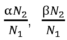
- 8N 1 curved arcs of the cross-sectional profile of the second screw includes N 1 circular arcs A 1 B 1 , N 1 circular arcs E 1 F 1 , 2N 1 circular arcs C 1 D 1 , 2N 1 non-circular arcs E 1 D 1 connecting circular arcs E 1 F 1 and circular arcs C 1 D 1 , 2N 2 non-circular arcs C 1 B 1 connecting circular arcs C 1 D 1 and circular arcs A 1 B 1 , diameters corresponding to A 1 B 1 , C 1 D 1 and E 1 F 1 are R,C-r M and r , central angles corresponding to A 1 B 1 , C 1 D 1 and E 1 F 1 are respectively ⁇ N 2 N 1 , ⁇ N 2 N 1 and ⁇ N 2 N 1 . .
- the first intermediate circular arc structure is provided on one side of the crest diameter of the first screw
- the second intermediate circular arc structure is provided on a side of the crest diameter of the second screw corresponding to the first intermediate circular arc structure
- the cross-sectional profile of the first screw is composed of 6N 2 curved arcs
- the cross-sectional profile of the second screw is composed of 6N 1 curved arcs
- 6N 1 curved arcs of the cross-sectional profile of the second screw include N 1 circular arcs A 1 B 1 , N 1 circular arcs E 1 F 1 , N 1 circular arcs C 1 D 1 , N 1 non-circular circular arcs E 1 D 1 connecting circular arcs E 1 F 1 and circular arcs C 1 D 1 , N 2 non-circular circular arcs C 1 B 1 connecting circular arcs C 1 D 1 and circular arcs A 1 B 1 , N 1 non-circular arcs F 1 A 1 connecting arcs E 1 F 1 and arcs A 1 B 1 , diameters corresponding to A 1 B 1 , C 1 D 1 and E 1 F 1 are R,C-r M and r, central angles corresponding to A 1 B 1 , C 1 D 1 and E 1 F 1 are respectively ⁇ N 2 N 1 , ⁇ N 2 N 1 and ⁇ N 2 N 1 . .
- the crest diameters of the first screw and the second screw are both tangent to a wall of an inner cavity of the barrel.
- the screw mechanism sequentially divides the inner cavity of the barrel into a conveying section, a melting section, an exhaust section, and a mixing and extrusion section; the barrel is provided with a feed port corresponding to the conveying section, an exhaust port corresponding to the exhaust section, a discharge port corresponding to an end of the mixing and extrusion section.
- the screw mechanism further includes a third screw having a same structure as the first screw, the third screw and the second screw are meshed with each other; the third screw and the first screw have a same rotating direction.
- both the first screw and the second screw adopt a tapered structure.
- the counter-rotating extruder according to claim 8 includes the counter-rotating differential speed extrusion device of any one of the above embodiments.
- the counter-rotating extruder according to the embodiment of the present disclosure has at least the following technical effects: the counter-rotating differential speed extrusion device realizes the self-cleaning during processing and enhances the disturbance effect, thus can effectively strengthen the melt plasticization and also have a more stable pressure building capability.
- the counter-rotating differential speed extrusion device realizes the self-cleaning during processing and enhances the disturbance effect, thus can effectively strengthen the melt plasticization and also have a more stable pressure building capability.
- the counter-rotating differential speed extrusion device realizes the self-cleaning during processing and enhances the disturbance effect, thus can effectively strengthen the melt plasticization and also have a more stable pressure building capability.
- the counter-rotating differential speed extrusion device realizes the self-cleaning during processing and enhances the disturbance effect, thus can effectively strengthen the melt plasticization and also have a more stable pressure building capability.
- the unmelted materials can be pushed forward at a faster speed than the melt under the action of positive displacement movement, and participates in the stirring process, thereby strengthening the melting
- the method for manufacturing materials according to independent claim 9 includes: adding materials; counter-rotating the first screw and the second screw, and advancing the materials through the first screw and the second screw; melting the materials by heat generated by the rotation of the first screw and the second screw and external heating to make the materials form a melt; stretching, compressing and kneading the melt through the first screw, the second screw, and the barrel to form a final target product.
- the method for manufacturing materials according to the embodiment of the present disclosure has at least the following technical effects: through the counter rotation of the first screw and the second screw, materials can be automatically pushed forward, at the same time, because of the specificity of the first screw and the second screw, the unmelted materials can be pushed forward along the groove axis at a faster speed than the melt under the action of positive displacement movement, and participates in the stirring process, thereby strengthening the plasticization and mixing and make the extrusion of the melted materials stable.
- the differential rotation between the first screw and the second screw also achieves better self-cleaning.
- FIGS. 1 to 12 a counter-rotating differential speed extrusion device according to an embodiment of the first aspect of the present disclosure will be described with reference to FIGS. 1 to 12 .
- a counter-rotating differential speed extrusion device includes: a barrel 100 and a screw mechanism 200 arranged in the barrel 100, the screw mechanism 200 includes a first screw 210 and a second screw 220, wherein a crest diameter and a root diameter of the first screw 210 are respectively meshed with a root diameter and a crest diameter of the second screw 220; at least one first intermediate circular arc structure 211 is provided between the root diameter and the crest diameter of the first screw 210, a second intermediate circular arc structure 221 that is tangent to the first intermediate circular arc structure 211 is provided between the root diameter and the crest diameter of the second screw 220; a trend of the first intermediate circular arc structure 211 is consistent with a trend of the crest diameter and the root diameter of the first screw 210; a trend of the second intermediate circular arc structure 221 is consistent with a trend of the root diameter and the crest diameter of the second screw 220.
- the crest diameter and the root diameter of the first screw 210 and the root diameter and the crest diameter of the second screw 220 are always in a state of intermeshing with each other, the first intermediate circular arc structure 211 and the second intermediate circular arc structure 221 also need to maintain a state of being always tangent.
- the number of the first intermediate circular arc structures 211 and the number of the second intermediate circular arc structures 221 may be multiple according to the difference in the rotation speed ratio.
- the first intermediate circular arc structure 211 may be disposed on one side or both sides of the crest diameter of the first screw 210, and the second intermediate circular arc structure 221 is also disposed on one side or both sides of the crest diameter of the second screw 220.
- 3 and 4 includes a conveying section 110 with an axially closed screw groove structure, a melting section 120 with an axially fully open screw groove structure, an exhaust section 130 with an axially closed screw groove structure, and a mixing and extrusion section 140 with an axially closed screw groove structure, which can ensure that the extruder can play a best role in each section.
- the existence of the first intermediate circular arc structure 211 and the second intermediate circular arc structure 221 will communicate the original left and right C-shaped chambers formed after the first screw 210 and the second screw 220 are meshed, and expanding to an overall "8"-shaped chamber, increasing a mixing effect.
- the first screw 210 and the second screw 220 always counter-rotate in differential rotation speed, so that the surfaces of the first screw 210 and the second screw 220 can be wiped with each other to achieve a self-cleaning effect.
- an upper meshing zone and a lower meshing zone are also formed, and local mixing and kneading pools are formed in the upper and lower meshing zones.
- the root diameter and crest diameter of the first screw 210 and the second screw 220 and the first intermediate circular arc structure 211 and the second intermediate circular arc structure 221 generally adopt a smooth spiral rib structures.
- the first screw 210 and the second screw 220 counter-rotate in differential speeds to wipe each other and realize the self-cleaning during the processing.
- the two screw grooves are opened to each other, the original closed C-shaped chamber positive displacement conveying unit is expanded to "8"-shaped chamber positive displacement conveying unit, which can effectively strengthen the melt plasticization and also have a more stable pressure-building ability.
- the ratio of frictional conveying and positive displacement conveying can be adjusted to control the pressure-building ability and extrusion characteristics of the screw structure.
- the first screw 210 and the second screw 220 form a local mixing and kneading pool in the upper and lower meshing zones, and the unmelted materials advances at a faster speed than the melt under the action of positive displacement movement, and participates in the stirring process, thus the melting and mixing are strengthened to form an adaptive melting mechanism, which effectively improves the processing flexibility of the screws.
- the rotation speed ratio of the first screw and the second screw is N 1 /N 2 , and N 1 and N 2 are positive integers that are relatively prime.
- a cross-sectional profile of the first screw 210 and a cross-sectional profile of the second screw 220 include multiple continuous curved arcs, and a number ratio of the curved arcs in the cross-sectional profile of the first screw 210 and the curved arcs in the cross-sectional profile of the second screw 220 is inversely proportional to the rotation speed ratio.
- the rotation speed ratio of the first screw 210 and the second screw 220 is N 1 /N 2 , and N 1 and N 2 are positive integers that are relatively prime, according to the principle of meshing conjugate, the number of threads of the first screw 210 and the second screw 220 are N 2 and N 1 , respectively.
- the number of threads here can be understood as: in the cross-sectional profile of the first screw 210 and the second screw 220 at the same place of the screw mechanism 200, the number of curved arcs included in the cross-sectional profile of the first screw 210 with a diameter equal to the crest diameter of the first screw 210 is N 2 , the number of curved arcs included in the cross-sectional profile of the second screw 220 with a corresponding diameter equal to the crest diameter of the second screw 220 is N 1 .
- the rotation speed ratio will be set to an integer ratio as much as possible, which can facilitate the design and manufacture of the extrusion device, as well as the calculation of performance.
- the cross-sectional profiles of the first screw 210 and the second screw 220 are also basically determined.
- a typical cross-sectional profile is selected here, it can be found that the cross-sectional profiles of the first intermediate circular arc structure 211 and the second intermediate circular arc structure 221 are not a standard arc, but a continuous multi-section curved arc.
- the continuous multi-section curved arc structure can ensure that the first intermediate circular arc structure 211 and the second intermediate circular arc structure 221 open the first screw 2102 and the second screw 220 in left and right sides at the same time while ensuring a high effect of strengthening melting and mixing.
- the numbers of circular arcs and non-circular arcs in the cross-sectional profiles of the first screw 210 and the second screw 220 need to be determined according to N 1 , N 2 , generally, the larger N 1 and N 2 are, the more the corresponding arcs and non-circular arcs are.
- a first intermediate circular arc structure 211 is provided on both sides of the crest diameter of the first screw 210
- a second intermediate circular arc structure 221 corresponding to the first intermediate circular arc structure 211 is provided on both sides of the crest diameter of the second screw 220.
- C is a distance of the connection line between rotation center O 1 of the first screw 210 and rotation center O 2 of the second screw 220.
- the first screw 210 is connected with 2N 2 first intermediate circular arc structures 211 between the root diameter and the crest diameter, that is, the first screw 210 is connected with a first intermediate circular arc structure 211 on both sides of the crest diameter, let the radius corresponding to the first intermediate circular arc structure 211 be r M , r ⁇ r M ⁇ R ⁇ 2N 1 second intermediate circular arc structures 221 corresponding to the first intermediate circular arc structure 211 are introduced into the cross-sectional profile of the second screw 220, and the radius corresponding to the second intermediate circular arc structure 221 is C-r M .
- the cross-sectional profile of the first screw 210 is composed of 8N 2 curved arcs;
- the cross-sectional profile of the second screw 220 is composed of 8N 1 curved arcs.
- the 8N 1 curved arcs of the cross-sectional profile of the second screw 220 includes N 1 circular arcs A 1 B 1 , N 1 circular arcs E 1 F 1 , 2N 1 circular arcs C 1 D 1 , 2N 1 non-circular arcs E 1 D 1 connecting circular arcs E 1 F 1 and circular arcs C 1 D 1 , 2N 2 non-circular arcs C 1 B 1 connecting circular arcs C 1 D 1 and circular arcs A 1 B 1 , corresponding diameters of A 1 B 1 , C 1 D 1 and E 1 F 1 are R, C-r M and r, central angles corresponding to A 1 B 1 , C 1 D 1 and E 1 F 1 are respectively ⁇ N 2 N 1 , ⁇ N 2 N 1 and ⁇ N 2 N 1 .
- ⁇ 4 t 4 arcsin r M sin N 1 t 4 C 2 + r M 2 ⁇ 2 Cr M cos N 1 t 4 ⁇ N 2 t 4
- the crest diameter of the first screw 210 is provided with a first intermediate circular arc structure 211 on only one side, a side of the crest diameter of the second screw 220 corresponding to the first intermediate circular arc structure 211 is provided with a second intermediate circular arc structure 221.
- FIGS. 6 , 8 and 10 which show the cross-sectional profiles of the first screw 210 and the second screw 220, where C is a distance of the connection line between rotation center O 1 of the first screw 210 and rotation center O 2 of the second screw 220.
- the root diameter and crest diameter of the first screw 210 are connected by N 2 first intermediate circular arc structure 211, that is, the crest diameter of the first screw 210 is connected with the first intermediate circular arc structure 211 only on one side, and the other side is directly connected to the root diameter through a non-circular arc, the radius corresponding to the first intermediate circular arc structure 211 is r M , r ⁇ r M ⁇ R.
- the arc radius corresponding to the N 1 second intermediate circular arc structure 221 introduced in the cross-sectional profile of the second screw 220 is C-r M .
- the cross-sectional profile of the first screw 210 is composed of 6N 2 curved arcs; the cross-sectional profile of the second screw 220 is composed of 6N 1 curved arcs.
- 6N 1 curved arcs of the cross-sectional profile of the second screw 220 include N 1 circular arcs A 1 B 1 , N 1 circular arcs E 1 F 1 , N 1 circular arcs C 1 D 1 , N 1 non-circular circular arcs E 1 D 1 connecting circular arcs E 1 F 1 and circular arcs C 1 D 1 , N 2 non-circular circular arcs C 1 B 1 connecting circular arcs C 1 D 1 and circular arcs A 1 B 1 , N1 non-circular arcs F 1 A 1 connecting arcs E 1 F 1 and arcs A 1 B 1 , corresponding diameters of A 1 B 1 , C 1 D 1 and E 1 F 1 are R, C-r M and r , central angles corresponding to A 1 B 1 , C 1 D 1 and E 1 F 1 are respectively ⁇ N 2 N 1 , ⁇ N 2 N 1 and ⁇ N 2 N 1 .
- the crest diameters of the first screw 210 and the second screw 220 are both tangent to the inner cavity wall of the barrel 100.
- the root diameter and crest diameter of the first screw 210 are equal to the root diameter and crest diameter of the second screw 220. This can bring greater disturbance and mixing effect.
- the first screw 210, the second screw 220 and the barrel 100 form a flow channel 30 for the passage of materials.
- the screw mechanism 200 divides the inner cavity of the barrel 100 into a conveying section 110, a melting section 120, an exhaust section 130, and a mixing and extrusion section 140 in sequence.
- the barrel 100 is provided with a feed port 111 corresponding to the conveying section 110, an exhaust port 131 corresponding to the exhaust section 130, and a discharge port 141 corresponding to an end of the mixing and extrusion section 140.
- the first screw 210 and the second screw 220 respectively rotate in different directions along the respective screw axes, thereby generating a conveying force.
- the cylindrical surface swept by the first intermediate circular arc structure 211 of the first screw 210 meshes with the cylindrical surface swept by the corresponding second intermediate circular arc structure 221 of the second screw 220, the screw grooves of the two screws form an open structure, forming an "8" shaped chamber positive displacement conveying unit, which increases the axial positive displacement conveying force.
- the materials moves in the direction of the melting section 120 under the combined action of the positive displacement conveying force and the friction force between the two screws.
- the first screw 210 and the second screw 220 form a mixing and kneading pool in the upper and lower meshing zones, under the action of positive displacement of the first screw 210 and the second screw 220, the unmelted materials advances along the screw groove axis at a faster speed than the melt, in this way, the melting and mixing are strengthened, an adaptive melting mechanism is formed, the heat transfer process is strengthened, and the melting process of solid materials is accelerated, so that the materials eventually become melts, which will be pushed into the exhaust section 130 by the first screw 210 and the second screw 220. If the heat generated by the high speed rotation of the first screw 210 and the second screw 220 is insufficient to melt the material, external heating means may be introduced in the melting section 120 to assist in heating and melting.
- the pushing and scraping action formed by the meshing of the first intermediate circular arc structure 211 and the second intermediate circular arc structure 221 promotes the interface renewal and expands the exhaust zone, the collection of materials creates a negative pressure here, which accelerates the exhaust gas discharged from the exhaust port 131. At the same time, the materials will be pushed into the mixing and extrusion section 140 by the first screw 210 and the second screw 220.
- the first screw 210 and the second screw 220 counter-rotate in differential speeds, meanwhile, because of the existence of the first intermediate circular arc structure 211 and the second intermediate circular arc structure 221, the first screw 210 and the second screw 220 have better pressure-building ability and extrusion characteristics, and, which also strengthens the mixing and plasticizing effect, so that the melted materials can be stably extruded from the discharge port 141.
- the screw mechanism 200 further includes a third screw with the same structure as the first screw 210, the third screw and the second screw 220 are always in mesh with each other, the third screw has the same rotation direction as the first screw 210.
- the use of a three-screw structure can bring greater extrusion effects and greater extrusion efficiency.
- the third screw may be substantially the same as the first screw 210 or the second screw 220. If it is the same as the first screw 210, it meshes with the second screw 220, and if it is the same as the second screw 220, it meshes with the first screw 210.
- FIGs 11 and 12 are schematic diagrams of the three-screw mechanism 200. Generally, the first screw 210, the second screw, and the third screw are arranged in an "in-line shape" and meshed according to the meshing situation.
- both the first screw 210 and the second screw 220 adopt a tapered structure.
- Adopting conical structure can provide stronger mixing and greater extrusion output.
- a counter-rotating extruder includes the counter-rotating differential speed extrusion device of any one of the above embodiment.
- the counter-rotating extruder realizes, by using the counter-rotating differential speed extrusion device, the self-cleaning during the processing and enhances the disturbance effect, thus can effectively strengthen the melt plasticization and also have a more stable pressure building capability.
- the counter-rotating differential speed extrusion device the unmelted materials can be pushed forward at a faster speed than the melt under the action of positive displacement movement, and participates in the stirring process, thereby strengthening the melting and mixing, forming an adaptive melting mechanism, effectively improving the processing flexibility of the screws.
- a method for manufacturing materials includes: adding materials; counter-rotating the first screw and the second screw in differential speeds, and advancing the materials through the first screw and the second screw; melting the materials by heat generated by the rotation of the first screw and the second screw and external heating to make the materials form a melt; stretching, compressing and kneading the melt through the first screw, the second screw, and the barrel to form a final target product.
- the method for manufacturing materials according to the embodiment of the present disclosure has at least the following technical effects: through the counter rotation of the first screw and the second screw, materials can be automatically pushed forward, at the same time, because of the specificity of the first screw and the second screw, the unmelted materials can be pushed forward along the groove axis at a faster speed than the melt under the action of positive displacement movement, and participates in the stirring process, thereby strengthening the plasticization and kneading and make the extrusion of the melted materials stable.
- the differential rotation between the first screw and the second screw also achieves better self-cleaning.
Landscapes
- Engineering & Computer Science (AREA)
- Mechanical Engineering (AREA)
- Physics & Mathematics (AREA)
- Algebra (AREA)
- General Physics & Mathematics (AREA)
- Mathematical Analysis (AREA)
- Mathematical Optimization (AREA)
- Mathematical Physics (AREA)
- Pure & Applied Mathematics (AREA)
- Extrusion Moulding Of Plastics Or The Like (AREA)
Description
- The present disclosure relates to the field of multi-screw extruders, and in particular relates to a counter-rotating differential speed extrusion device, an extruder and a related method for manufacturing materials.
- Co-rotating multi-screw extruder and counter-rotating multi-screw extruder mainly include a barrel and multiple screws installed in an inner cavity of the barrel, where, intermeshing counter-rotating twin-screw extruder is the most widely used in counter-rotating multi-screw extruder. The traditional counter-rotating twin-screw extruder adopts the working mode of two screws rotating in opposite directions at the same speed, the materials is enclosed in several independent C-shaped chambers and pushed towards the outlet, thus the traditional counter-rotating twin-screw extruder has good pressure-building ability, thus is widely used in the extrusion molding process.
- Currently, in order to change the mixing and melting efficiency in the meshing zone, differential speed counter-rotating twin screws have appeared. Referring to
Fig. 1 , the differential speed counter-rotating twin screws strengthens the dispersion and mixing effect by introducing a larger speed difference in the meshing zone, but the fact that the materials is still enclosed in several independent C-shaped chambers has not changed, there is still no mixing relationship between different screws and between the upstream and downstream of the screw, which has led to a limited effect on mixing. In such a screw configuration, through meshing displacement relationship, the C-shaped chamber is pushed axially from the inlet to the outlet, and the materials is enclosed in the same C-shaped chamber to complete the melting, mixing and exhausting process. The upstream and downstream of the screw lack the adaptive mechanism of the melting process, when the output increases, it is easy to cause unmelted solid materials to block the screw channel, resulting in a significant increase in energy consumption. - There are many instances where such proposed solution to counter-rotate a first and second screw in differential speeds. For example,
U.S. Patent Application No. 3,501,807, filed on September 8, 1967, by Hans Werner Selbach, et al. , entitled "MASTICATING SYSTEM FOR PLASTIC MATERIALS", discloses a masticating device for plasticizing a synthetic-resin material,U.S. Patent Application No. 3,104,420, filed on December 5, 1961, by Hans Werner Selbach, et al. , entitled "MASTICATOR FOR PLASTIC MATERIALS", discloses a masticator for the plastification of moldable material, S.U. Patent Application No.1634511, filed on March 15, 1991, by Konovalov Sergej V, et al. , entitled "SCREW MIXER FOR PROCESSING POLYMERS", discloses an equipment for the processing of polymeric materials,J.P. Patent Application No. H0557725, filed on March 9, 1993, by Nakamura Kensaku, et al. C.N. Patent Application No. 201720512864.0, filed May 9, 2017, by Baiping XU et al. - The present disclosure aims to address at least one of the technical problems existing in the prior art. For this purpose, the present disclosure proposes a counter-rotating differential speed extrusion device. The counter-rotating differential speed extrusion device has a simple structure, thus improves the melting and mixing effect, and solves the problem of solid materials blocking the screw channel. The present disclosure also proposes a counter-rotating extruder and a method for manufacturing materials.
- The counter-rotating differential speed extrusion device according to
independent claim 1 includes a barrel and a screw mechanism arranged in the barrel, the screw mechanism includes a first screw and a second screw, wherein a crest diameter and a root diameter of the first screw are respectively meshed with a root diameter and a crest diameter of the second screw; the first screw (210) and the second screw (220) are configured for counter-rotating in differential speeds at a fixed rotation speed ratio;
at least one first intermediate circular arc structure is provided between the root diameter and the crest diameter of the first screw, a second intermediate circular arc structure that is tangent to the first intermediate circular arc structure is provided between the root diameter and the crest diameter of the second screw; a trend of the first intermediate circular arc structure is consistent with a trend of the crest diameter and the root diameter of the first screw; a trend of the second intermediate circular arc structure is consistent with a trend of the root diameter and the crest diameter of the second screw. - The counter-rotating differential speed extrusion device according to the invention has at least the following technical effects: the first screw and the second screw rotate in different directions to achieve mutual wiping between the two screws, and achieve self-cleaning during processing; through the first intermediate circular arc structure provided between the root diameter and the crest diameter of the first screw and the second intermediate circular arc structure provided between the root diameter and the crest diameter of the second screw, the two screw grooves are open to each other, the original closed C-shaped chamber positive displacement conveying unit is expanded to "8"-shaped chamber positive displacement conveying unit, which can effectively strengthen the melt plasticization and also have a more stable pressure-building ability. And by controlling the number of the first intermediate circular arc structure and the second intermediate circular arc to adjust the degree of axial opening or closing in the meshing zone, therefore, the ratio of frictional conveying and positive displacement conveying can be adjusted to control the pressure-building ability and extrusion characteristics of the screw structure. In addition, the first screw and the second screw form a local mixing and kneading pool in the upper and lower meshing zones, and the unmelted materials advances at a faster speed than the melt under the action of positive displacement movement, and participates in the stirring process, thereby strengthening the melting and mixing, forming an adaptive melting mechanism, effectively improving the processing flexibility of the screws.
- Furthermore, still according to the invention as claimed in
independent claim 1, the rotation speed ratio of the first screw and the second screw is N1/N2, and N1 and N2 are positive integers that are relatively prime; in each cross section of the screw mechanism, a cross-sectional profile of the first screw and a cross-sectional profile of the second screw include multiple continuous curved arcs, and a number ratio of the curved arcs of the cross-sectional profile of the first screw and the curved arcs of the cross-sectional profile of the second screw is inversely proportional to the rotation speed ratio. - According to some embodiments of the present disclosure, the first intermediate circular arc structure is provided on both sides of the crest diameter of the first screw, the second intermediate circular arc structure is provided on both sides of the crest diameter of the second screw; the cross-sectional profile of the first screw is composed of 8N2 curved arcs; the cross-sectional profile of the second screw is composed of 8N1 curved arcs;
- the 8N2 curved arcs of the cross-sectional profile of the first screw includes N2 circular arcs AB, N2 circular arcs EF, 2N2 circular arcs CD, and 2N2 non-circular arcs ED connecting circular arc EF and circular arc CD, 2N2 non-circular arcs CB connecting circular arc CD and circular arc AB; diameters corresponding to AB, CD and EF are R, rM and r, and central angles corresponding to AB, CD and EF are α, β, and γ, respectively, parameters Ø1,Ø2 are given, then Ø1,Ø2 satisfy the following relational expressions:


the central angles α, β, and γ satisfy the following relational expression:

- 8N1 curved arcs of the cross-sectional profile of the second screw includes N1 circular arcs A1B1, N1 circular arcs E1F1, 2N1 circular arcs C1D1, 2N1 non-circular arcs E1D1 connecting circular arcs E1F1 and circular arcs C1D1, 2N2 non-circular arcs C1B1 connecting circular arcs C1D1 and circular arcs A1B1, diameters corresponding to A1B1, C1D1 and E1F1 are R,C-r M and r, central angles corresponding to A1B1, C1D1 and E1F1 are respectively


- According to some embodiments of the present disclosure, the first intermediate circular arc structure is provided on one side of the crest diameter of the first screw, the second intermediate circular arc structure is provided on a side of the crest diameter of the second screw corresponding to the first intermediate circular arc structure; the cross-sectional profile of the first screw is composed of 6N2 curved arcs; the cross-sectional profile of the second screw is composed of 6N1 curved arcs;
- 6N2 circular arcs of the cross-sectional profile of the first screw includes N2 circular arcs AB, N2 circular arcs EF, N2 circular arcs CD, N2 non-circular arcs ED connecting circular arc EF and circular arc CD, N2 non-circular arcs CB connecting circular arc CD and circular arc AB, N2 non-circular arcs FA connecting circular arc EF and circular arc AB; diameters corresponding to AB, CD and EF are R, rM and r, and central angles corresponding to AB, CD and EF are α, β, and γ, respectively, parameters Ø1, Ø2, Ø3 are given, then Ø1, Ø2, Ø3 satisfy the following relational expression:


- 6N1 curved arcs of the cross-sectional profile of the second screw include N1 circular arcs A1B1, N1 circular arcs E1F1, N1 circular arcs C1D1, N1 non-circular circular arcs E1D1 connecting circular arcs E1F1 and circular arcs C1D1, N2 non-circular circular arcs C1B1 connecting circular arcs C1D1 and circular arcs A1B1, N1 non-circular arcs F1A1 connecting arcs E1F1 and arcs A1B1, diameters corresponding to A1B1, C1D1 and E1F1 are R,C-r M and r, central angles corresponding to A1B1, C1D1 and E1F1 are respectively

- According to some embodiments of the present disclosure, the crest diameters of the first screw and the second screw are both tangent to a wall of an inner cavity of the barrel.
- According to some embodiments of the present disclosure, the screw mechanism sequentially divides the inner cavity of the barrel into a conveying section, a melting section, an exhaust section, and a mixing and extrusion section; the barrel is provided with a feed port corresponding to the conveying section, an exhaust port corresponding to the exhaust section, a discharge port corresponding to an end of the mixing and extrusion section.
- According to some embodiments of the present disclosure, the screw mechanism further includes a third screw having a same structure as the first screw, the third screw and the second screw are meshed with each other; the third screw and the first screw have a same rotating direction.
- According to some embodiments of the present disclosure, both the first screw and the second screw adopt a tapered structure.
- The counter-rotating extruder according to claim 8 includes the counter-rotating differential speed extrusion device of any one of the above embodiments.
- The counter-rotating extruder according to the embodiment of the present disclosure has at least the following technical effects: the counter-rotating differential speed extrusion device realizes the self-cleaning during processing and enhances the disturbance effect, thus can effectively strengthen the melt plasticization and also have a more stable pressure building capability. In addition, through the counter-rotating differential speed extrusion device, the unmelted materials can be pushed forward at a faster speed than the melt under the action of positive displacement movement, and participates in the stirring process, thereby strengthening the melting and mixing, forming an adaptive melting mechanism, effectively improving the processing flexibility of the screw.
- The method for manufacturing materials according to independent claim 9 includes: adding materials; counter-rotating the first screw and the second screw, and advancing the materials through the first screw and the second screw; melting the materials by heat generated by the rotation of the first screw and the second screw and external heating to make the materials form a melt; stretching, compressing and kneading the melt through the first screw, the second screw, and the barrel to form a final target product.
- The method for manufacturing materials according to the embodiment of the present disclosure has at least the following technical effects: through the counter rotation of the first screw and the second screw, materials can be automatically pushed forward, at the same time, because of the specificity of the first screw and the second screw, the unmelted materials can be pushed forward along the groove axis at a faster speed than the melt under the action of positive displacement movement, and participates in the stirring process, thereby strengthening the plasticization and mixing and make the extrusion of the melted materials stable. At the same time, the differential rotation between the first screw and the second screw also achieves better self-cleaning.
- Additional aspects and advantages of the present disclosure will be partially given in the following description, and some will become apparent from the following description, or can be learned through the practice of the present disclosure.
- The above and / or additional aspects and advantages of the present disclosure will become apparent and easily understood from the description of the embodiments in conjunction with the following drawings, in which:
-
FIG. 1 is a schematic structural view of a conventional counter-rotating differential speed twin screw with a rotation speed ratio of 3: 1; -
FIG. 2 is a schematic structural view of a twin screw with an axially closed screw groove and a rotation speed ratio of 2: 1 (except the barrel) according to an embodiment of the first aspect of the present disclosure; -
FIG. 3 is a schematic structural view of a twin screw with a rotation speed ratio of 2: 1 according to an embodiment of the first aspect of the present disclosure; -
FIG. 4 is a schematic sectional view of the extrusion device shown inFIG. 3 ; -
FIG. 5 is a schematic view of the cross-sectional profile of an extrusion device (except the barrel) with a rotation speed ratio of 2:1 and an axially fully open screw groove according to an embodiment of the first aspect of the present disclosure; -
FIG. 6 is a schematic view of the cross-sectional profile of an extrusion device (except the barrel) with a rotation speed ratio of 2:1 and an axially closed screw groove according to an embodiment of the first aspect of the present disclosure; -
FIG. 7 is a schematic view of the cross-sectional profile of an extrusion device (except the barrel) with a rotation speed ratio of 3:1 and an axially fully open screw groove according to an embodiment of the first aspect of the present disclosure; -
FIG. 8 is a schematic view of the cross-sectional profile of an extrusion device (except the barrel) with a rotation speed ratio of 3:1 and an axially closed screw groove according to an embodiment of the first aspect of the present disclosure; -
FIG. 9 is a schematic view of the cross-sectional profile of an extrusion device (except the barrel) with a rotation speed ratio of 3:2 and an axially fully open screw groove according to an embodiment of the first aspect of the present disclosure; -
FIG. 10 is a schematic view of the cross-sectional profile of an extrusion device (except the barrel) with a rotation speed ratio of 2:1 and an axially closed screw groove according to an embodiment of the first aspect of the present disclosure; -
FIG. 11 is a schematic diagram of a three-screw structure (one fast and two slow) according to an embodiment of the first aspect of the present disclosure; -
FIG. 12 is a schematic diagram of a three-screw structure (one slow and two fast) according to an embodiment of the first aspect of the present disclosure. -
-
Barrel 100, - Conveying
section 110, - Feed
port 111, -
Melting section 120, -
Exhaust section 130, -
Exhaust port 131, - Mixing and
extrusion section 140, -
Discharge port 141, -
Screw mechanism 200, -
First screw 210, - First intermediate
circular arc structure 211, -
Second screw 220, - Second intermediate
circular arc structure 221, -
Flow channel 300. - The following describes in detail embodiments of the present disclosure, examples of which are shown in the drawings, wherein the same or similar reference numbers indicate the same or similar elements or elements with the same or similar functions throughout.
- In the description of the present disclosure, the terms such as first, second, third, fourth, if described, are just for the purpose of distinguishing technical features, it cannot be understood as indicating or implying relative importance or implicitly indicating the number of indicated technical features or impliedly indicating the sequence of indicated technical features.
- In the description of the present disclosure, unless otherwise clearly defined, words such as arranging and connecting should be understood in a broad sense, and those skilled in the art can reasonably determine the specific meaning of the above words in the present disclosure in conjunction with the specific content of the technical solution.
- Hereinafter, a counter-rotating differential speed extrusion device according to an embodiment of the first aspect of the present disclosure will be described with reference to
FIGS. 1 to 12 . - According to an embodiment of the first aspect of the present disclosure, a counter-rotating differential speed extrusion device includes: a
barrel 100 and ascrew mechanism 200 arranged in thebarrel 100, thescrew mechanism 200 includes afirst screw 210 and asecond screw 220, wherein a crest diameter and a root diameter of thefirst screw 210 are respectively meshed with a root diameter and a crest diameter of thesecond screw 220; at least one first intermediatecircular arc structure 211 is provided between the root diameter and the crest diameter of thefirst screw 210, a second intermediatecircular arc structure 221 that is tangent to the first intermediatecircular arc structure 211 is provided between the root diameter and the crest diameter of thesecond screw 220; a trend of the first intermediatecircular arc structure 211 is consistent with a trend of the crest diameter and the root diameter of thefirst screw 210; a trend of the second intermediatecircular arc structure 221 is consistent with a trend of the root diameter and the crest diameter of thesecond screw 220. - Referring to
Figures 2 to 4 , the crest diameter and the root diameter of thefirst screw 210 and the root diameter and the crest diameter of thesecond screw 220 are always in a state of intermeshing with each other, the first intermediatecircular arc structure 211 and the second intermediatecircular arc structure 221 also need to maintain a state of being always tangent. The number of the first intermediatecircular arc structures 211 and the number of the second intermediatecircular arc structures 221 may be multiple according to the difference in the rotation speed ratio. The first intermediatecircular arc structure 211 may be disposed on one side or both sides of the crest diameter of thefirst screw 210, and the second intermediatecircular arc structure 221 is also disposed on one side or both sides of the crest diameter of thesecond screw 220. When the existence states (whether it exists on both sides or one side of the crest diameter) and the number of the first intermediatecircular arc structure 211 and the second intermediatecircular arc structure 221 are changed, it is possible to adjust the axial opening and closing of the upstream and downstream screw grooves, thereby changing the axial mixing capacity and meeting different mixing capacity requirements. For example, when the crest diameter of thefirst screw 210 is connected with the first intermediatecircular arc structure 211 on both sides, and the crest diameter of thesecond screw 220 is connected with the second intermediatecircular arc structure 221 on both sides, a structure in which the screw groove is axially fully opened can be realized, thus increasing the axial mixing and adaptive melting ability; when the crest diameter of thefirst screw 210 is connected with the first intermediatecircular arc structure 211 on only one side, and the crest diameter of thesecond screw 220 is connected with the second intermediatecircular arc structure 221 on only one side, a structure in which the screw groove is axially closed can be realized, which can effectively improve the positive displacement conveying capacity. With further reference toFIGS. 3 and 4 , the device inFIGS. 3 and 4 includes a conveyingsection 110 with an axially closed screw groove structure, amelting section 120 with an axially fully open screw groove structure, anexhaust section 130 with an axially closed screw groove structure, and a mixing andextrusion section 140 with an axially closed screw groove structure, which can ensure that the extruder can play a best role in each section. - At the same time, the existence of the first intermediate
circular arc structure 211 and the second intermediatecircular arc structure 221 will communicate the original left and right C-shaped chambers formed after thefirst screw 210 and thesecond screw 220 are meshed, and expanding to an overall "8"-shaped chamber, increasing a mixing effect. Thefirst screw 210 and thesecond screw 220 always counter-rotate in differential rotation speed, so that the surfaces of thefirst screw 210 and thesecond screw 220 can be wiped with each other to achieve a self-cleaning effect. In addition, after thefirst screw 210 and thesecond screw 220 are meshed, an upper meshing zone and a lower meshing zone are also formed, and local mixing and kneading pools are formed in the upper and lower meshing zones. In some embodiments, the root diameter and crest diameter of thefirst screw 210 and thesecond screw 220 and the first intermediatecircular arc structure 211 and the second intermediatecircular arc structure 221 generally adopt a smooth spiral rib structures. - In the counter-rotating differential speed extrusion device according to the embodiment of the present disclosure, the
first screw 210 and thesecond screw 220 counter-rotate in differential speeds to wipe each other and realize the self-cleaning during the processing. Through the first intermediatecircular arc structure 211 provided between the root diameter and crest diameter of thefirst screw 210 and the second intermediatecircular arc structure 221 provided between the root diameter and crest diameter of thesecond screw 220, the two screw grooves are opened to each other, the original closed C-shaped chamber positive displacement conveying unit is expanded to "8"-shaped chamber positive displacement conveying unit, which can effectively strengthen the melt plasticization and also have a more stable pressure-building ability. And by controlling the number of the first intermediatecircular arc structure 211 and the second intermediate circular arc to adjust the axial opening or closing degree in the meshing zone, therefore, the ratio of frictional conveying and positive displacement conveying can be adjusted to control the pressure-building ability and extrusion characteristics of the screw structure. In addition, thefirst screw 210 and thesecond screw 220 form a local mixing and kneading pool in the upper and lower meshing zones, and the unmelted materials advances at a faster speed than the melt under the action of positive displacement movement, and participates in the stirring process, thus the melting and mixing are strengthened to form an adaptive melting mechanism, which effectively improves the processing flexibility of the screws. - According to the invention the rotation speed ratio of the first screw and the second screw is N1/N2, and N1 and N2 are positive integers that are relatively prime. In each cross section of the
screw mechanism 200, a cross-sectional profile of thefirst screw 210 and a cross-sectional profile of thesecond screw 220 include multiple continuous curved arcs, and a number ratio of the curved arcs in the cross-sectional profile of thefirst screw 210 and the curved arcs in the cross-sectional profile of thesecond screw 220 is inversely proportional to the rotation speed ratio. The rotation speed ratio of thefirst screw 210 and thesecond screw 220 is N1/N2, and N1 and N2 are positive integers that are relatively prime, according to the principle of meshing conjugate, the number of threads of thefirst screw 210 and thesecond screw 220 are N2 and N1, respectively. The number of threads here can be understood as: in the cross-sectional profile of thefirst screw 210 and thesecond screw 220 at the same place of thescrew mechanism 200, the number of curved arcs included in the cross-sectional profile of thefirst screw 210 with a diameter equal to the crest diameter of thefirst screw 210 is N2, the number of curved arcs included in the cross-sectional profile of thesecond screw 220 with a corresponding diameter equal to the crest diameter of thesecond screw 220 is N1. Usually in actual engineering, the rotation speed ratio will be set to an integer ratio as much as possible, which can facilitate the design and manufacture of the extrusion device, as well as the calculation of performance. Meanwhile, generally, after the rotation speed ratio is determined, the cross-sectional profiles of thefirst screw 210 and thesecond screw 220 are also basically determined. Referring toFigure 5 , a typical cross-sectional profile is selected here, it can be found that the cross-sectional profiles of the first intermediatecircular arc structure 211 and the second intermediatecircular arc structure 221 are not a standard arc, but a continuous multi-section curved arc. The continuous multi-section curved arc structure can ensure that the first intermediatecircular arc structure 211 and the second intermediatecircular arc structure 221 open the first screw 2102 and thesecond screw 220 in left and right sides at the same time while ensuring a high effect of strengthening melting and mixing. The numbers of circular arcs and non-circular arcs in the cross-sectional profiles of thefirst screw 210 and thesecond screw 220 need to be determined according to N1, N2, generally, the larger N1 and N2 are, the more the corresponding arcs and non-circular arcs are. - In some embodiments of the present disclosure, in order to realize the axially fully open screw groove, increase the axial mixing and adaptive melting ability, generally, a first intermediate
circular arc structure 211 is provided on both sides of the crest diameter of thefirst screw 210, a second intermediatecircular arc structure 221 corresponding to the first intermediatecircular arc structure 211 is provided on both sides of the crest diameter of thesecond screw 220. Referring toFigure 5 ,Figure 7 andFigure 9 which show the cross-sectional profiles of thefirst screw 210 and thesecond screw 220, where C is a distance of the connection line between rotation center O1 of thefirst screw 210 and rotation center O2 of thesecond screw 220. The crest diameters of thefirst screw 210 and thesecond screw 220 are both D, and the corresponding radius is R, the root diameters of thefirst screw 210 and thesecond screw 220 are both d, and the corresponding radius is r, then r = C-R. Thefirst screw 210 is connected with 2N2 first intermediatecircular arc structures 211 between the root diameter and the crest diameter, that is, thefirst screw 210 is connected with a first intermediatecircular arc structure 211 on both sides of the crest diameter, let the radius corresponding to the first intermediatecircular arc structure 211 be r M , r < rM < R ∘ 2N1 second intermediatecircular arc structures 221 corresponding to the first intermediatecircular arc structure 211 are introduced into the cross-sectional profile of thesecond screw 220, and the radius corresponding to the second intermediatecircular arc structure 221 is C-rM. At this time, the cross-sectional profile of thefirst screw 210 is composed of 8N2 curved arcs; the cross-sectional profile of thesecond screw 220 is composed of 8N1 curved arcs. - 8N2 curved arcs of the cross-sectional profile of the
first screw 210 includes N2 circular arcs AB, N2 circular arcs EF, 2N2 circular arcs CD, and 2N2 non-circular arcs ED connecting circular arc EF and circular arc CD, 2N2 non-circular arcs CB connecting circular arc CD and circular arc AB; diameters corresponding to AB, CD and EF are R, rM and r, and central angles corresponding to AB, CD and EF are α, β, and γ, respectively, parameters Ø1,Ø2 are given, then Ø1,Ø2 satisfy the following relational expressions:

the central angles α, β, and γ satisfy the following relational expression:
- For the non-circular curved arc ED, by taking O1E as a polar radius, introducing an auxiliary angle t1 is introduced, and taking the counterclockwise direction as a positive direction, the polar angle θ 1(t) of the non-circular curved arc ED is expressed as:

the corresponding polar radius ρ1(t 1) is:

- For the non-circular arc CB, by taking O1C as a polar radius, introducing an auxiliary angle ε 2(t 2), and taking the counterclockwise direction as a positive direction, the polar angle θ 2(t 2) of the non-circular curved arc CB is:

the corresponding polar radius ρ2(t 2) is:

- Correspondingly, the 8N1 curved arcs of the cross-sectional profile of the
second screw 220 includes N1 circular arcs A1B1, N1 circular arcs E1F1, 2N1 circular arcs C1D1, 2N1 non-circular arcs E1D1 connecting circular arcs E1F1 and circular arcs C1D1, 2N2 non-circular arcs C1B1 connecting circular arcs C1D1 and circular arcs A1B1, corresponding diameters of A1B1, C1D1 and E1F1 are R, C-r M and r, central angles corresponding to A1B1, C1D1 and E1F1 are respectively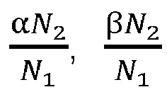

- For the non-circular arc E1D1, by taking O2E1 as a polar radius, introducing an auxiliary angle t3, and taking the counterclockwise direction as a positive direction, the polar angle θ 3(t 3) of the non-circular arc E1D1 is expressed as:


- For non-circular curved arc C1B1, by taking O2C1 as a polar radius, introducing an auxiliary angle t4, and taking the counterclockwise direction as a positive direction, the polar angle θ 4(t 4) of the non-circular curved arc C1B1 is expressed as:

the corresponding polar radius ρ4(t 4) is:

where,
- In some embodiments of the present disclosure, in order to realize the axially closed screw groove and improve the positive displacement conveying capacity, the crest diameter of the
first screw 210 is provided with a first intermediatecircular arc structure 211 on only one side, a side of the crest diameter of thesecond screw 220 corresponding to the first intermediatecircular arc structure 211 is provided with a second intermediatecircular arc structure 221. Referring toFIGS. 6 ,8 and10 which show the cross-sectional profiles of thefirst screw 210 and thesecond screw 220, where C is a distance of the connection line between rotation center O1 of thefirst screw 210 and rotation center O2 of thesecond screw 220. The crest diameters of thefirst screw 210 and thesecond screw 220 are both D, the corresponding radius is R; the root diameters of thefirst screw 210 and thesecond screw 220 are both d, and the corresponding radius is r, then r = C-R. The root diameter and crest diameter of thefirst screw 210 are connected by N2 first intermediatecircular arc structure 211, that is, the crest diameter of thefirst screw 210 is connected with the first intermediatecircular arc structure 211 only on one side, and the other side is directly connected to the root diameter through a non-circular arc, the radius corresponding to the first intermediatecircular arc structure 211 is rM, r < rM < R. The arc radius corresponding to the N1 second intermediatecircular arc structure 221 introduced in the cross-sectional profile of thesecond screw 220 is C-rM. At this time, the cross-sectional profile of thefirst screw 210 is composed of 6N2 curved arcs; the cross-sectional profile of thesecond screw 220 is composed of 6N1 curved arcs. - 6N2 circular arcs of the cross-sectional profile of the
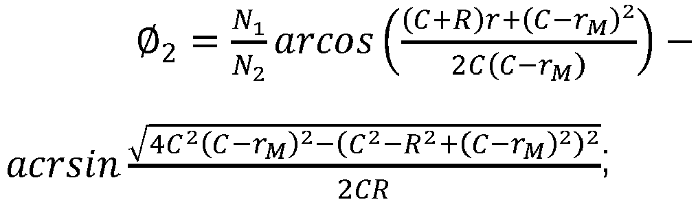
first screw 210 includes N2 circular arcs AB, N2 circular arcs EF, N2 circular arcs CD, N2 non-circular arcs ED connecting circular arc EF and circular arc CD, N2 non-circular arcs CB connecting circular arc CD and circular arc AB, N2 non-circular arcs FA connecting circular arc EF and circular arc AB; diameters corresponding to AB, CD and EF are R, rM and r, and central angles corresponding to AB, CD and EF are α, β, and γ, respectively, parameters Ø1, Ø2, Ø3 are given, the Ø1, Ø2, Ø3 satisfy the following relational expression:

- The central angles α, β, and γ satisfy the following relational expression:

- For the non-circular curved arc ED, by taking O1E as a polar radius, introducing an auxiliary angle t1, and taking the counterclockwise direction as a positive direction, the polar angle θ 1(t) of the non-circular curved arc ED is:

the corresponding polar radius ρ1(t 1) is:

- For the non-circular arc CB, by taking O1C as a polar radius, introducing an auxiliary angle ε 2(t 2), and taking the counterclockwise direction as a positive direction, the polar angle θ 2(t 2) of the non-circular arc CB is:

the corresponding polar radius ρ2(t 2) is:

where,
- For the non-circular arc FA, by taking O1F as a polar radius, introducing an auxiliary angle t3, and taking the counterclockwise direction as a positive direction, the polar angle θ 3(t 3) of the non-circular arc FA is:

the corresponding polar radius ρ3(t 3) is:

where,
- 6N1 curved arcs of the cross-sectional profile of the
second screw 220 include N1 circular arcs A1B1, N1 circular arcs E1F1, N1 circular arcs C1D1, N1 non-circular circular arcs E1D1 connecting circular arcs E1F1 and circular arcs C1D1, N2 non-circular circular arcs C1B1 connecting circular arcs C1D1 and circular arcs A1B1, N1 non-circular arcs F1A1 connecting arcs E1F1 and arcs A1B1, corresponding diameters of A1B1, C1D1 and E1F1 are R, C-r M and r, central angles corresponding to A1B1, C1D1 and E1F1 are respectively

- For the non-circular arc E1D1, by taking O2E1 as a polar radius, introducing an auxiliary angle t4, and taking the counterclockwise direction as a positive direction, the polar angle θ 4(t 4) of the non-circular arc E1D1 is:

the corresponding polar radius ρ4(t 4) is:

- For the non-circular curved arc C1B1, by taking O2C1 as a polar radius, introducing an auxiliary angle t5, and taking the counterclockwise direction as a positive direction, the polar angle θ 5(t 5) of the non-circular arc C1B1 is:

the corresponding polar radius ρ5(t 5) is:

- For the non-circular curved arc F1A1, by taking O2F1 as a polar radius, introducing an auxiliary angle t6, and taking the counterclockwise direction as a positive direction, the polar angle θ 6(t 6) of the non-circular arc F1A1 is:

the corresponding polar radius ρ6(t 6) is:

- In some embodiments of the present disclosure, referring to
FIGS. 3 and 4 , the crest diameters of thefirst screw 210 and thesecond screw 220 are both tangent to the inner cavity wall of thebarrel 100. The root diameter and crest diameter of thefirst screw 210 are equal to the root diameter and crest diameter of thesecond screw 220. This can bring greater disturbance and mixing effect. - In some embodiments of the present disclosure, referring to
FIGS. 3 and 4 , thefirst screw 210, thesecond screw 220 and thebarrel 100 form a flow channel 30 for the passage of materials. - In some embodiments of the present disclosure, referring to
FIG. 4 , thescrew mechanism 200 divides the inner cavity of thebarrel 100 into a conveyingsection 110, amelting section 120, anexhaust section 130, and a mixing andextrusion section 140 in sequence. Thebarrel 100 is provided with afeed port 111 corresponding to the conveyingsection 110, anexhaust port 131 corresponding to theexhaust section 130, and adischarge port 141 corresponding to an end of the mixing andextrusion section 140. - In the conveying
section 110, thefirst screw 210 and thesecond screw 220 respectively rotate in different directions along the respective screw axes, thereby generating a conveying force. At the same time, the cylindrical surface swept by the first intermediatecircular arc structure 211 of thefirst screw 210 meshes with the cylindrical surface swept by the corresponding second intermediatecircular arc structure 221 of thesecond screw 220, the screw grooves of the two screws form an open structure, forming an "8" shaped chamber positive displacement conveying unit, which increases the axial positive displacement conveying force. The materials moves in the direction of themelting section 120 under the combined action of the positive displacement conveying force and the friction force between the two screws. - In the
melting section 120, thefirst screw 210 and thesecond screw 220 form a mixing and kneading pool in the upper and lower meshing zones, under the action of positive displacement of thefirst screw 210 and thesecond screw 220, the unmelted materials advances along the screw groove axis at a faster speed than the melt, in this way, the melting and mixing are strengthened, an adaptive melting mechanism is formed, the heat transfer process is strengthened, and the melting process of solid materials is accelerated, so that the materials eventually become melts, which will be pushed into theexhaust section 130 by thefirst screw 210 and thesecond screw 220. If the heat generated by the high speed rotation of thefirst screw 210 and thesecond screw 220 is insufficient to melt the material, external heating means may be introduced in themelting section 120 to assist in heating and melting. - In the
exhaust section 130, the pushing and scraping action formed by the meshing of the first intermediatecircular arc structure 211 and the second intermediatecircular arc structure 221 promotes the interface renewal and expands the exhaust zone, the collection of materials creates a negative pressure here, which accelerates the exhaust gas discharged from theexhaust port 131. At the same time, the materials will be pushed into the mixing andextrusion section 140 by thefirst screw 210 and thesecond screw 220. In the mixing andextrusion section 140, thefirst screw 210 and thesecond screw 220 counter-rotate in differential speeds, meanwhile, because of the existence of the first intermediatecircular arc structure 211 and the second intermediatecircular arc structure 221, thefirst screw 210 and thesecond screw 220 have better pressure-building ability and extrusion characteristics, and, which also strengthens the mixing and plasticizing effect, so that the melted materials can be stably extruded from thedischarge port 141. - In some embodiments of the present disclosure, the
screw mechanism 200 further includes a third screw with the same structure as thefirst screw 210, the third screw and thesecond screw 220 are always in mesh with each other, the third screw has the same rotation direction as thefirst screw 210. The use of a three-screw structure can bring greater extrusion effects and greater extrusion efficiency. Because thefirst screw 210 and thesecond screw 220 themselves are not specifically limited, therefore, the third screw may be substantially the same as thefirst screw 210 or thesecond screw 220. If it is the same as thefirst screw 210, it meshes with thesecond screw 220, and if it is the same as thesecond screw 220, it meshes with thefirst screw 210.FIGs 11 and 12 are schematic diagrams of the three-screw mechanism 200. Generally, thefirst screw 210, the second screw, and the third screw are arranged in an "in-line shape" and meshed according to the meshing situation. - In some embodiments of the present disclosure, both the
first screw 210 and thesecond screw 220 adopt a tapered structure. Adopting conical structure can provide stronger mixing and greater extrusion output. - According to an embodiment of a second aspect of the present disclosure, a counter-rotating extruder includes the counter-rotating differential speed extrusion device of any one of the above embodiment.
- The counter-rotating extruder according to the embodiment of the present disclosure realizes, by using the counter-rotating differential speed extrusion device, the self-cleaning during the processing and enhances the disturbance effect, thus can effectively strengthen the melt plasticization and also have a more stable pressure building capability. In addition, through the counter-rotating differential speed extrusion device, the unmelted materials can be pushed forward at a faster speed than the melt under the action of positive displacement movement, and participates in the stirring process, thereby strengthening the melting and mixing, forming an adaptive melting mechanism, effectively improving the processing flexibility of the screws.
- According to an embodiment of a third aspect of the present disclosure, a method for manufacturing materials includes: adding materials; counter-rotating the first screw and the second screw in differential speeds, and advancing the materials through the first screw and the second screw; melting the materials by heat generated by the rotation of the first screw and the second screw and external heating to make the materials form a melt; stretching, compressing and kneading the melt through the first screw, the second screw, and the barrel to form a final target product.
- The method for manufacturing materials according to the embodiment of the present disclosure has at least the following technical effects: through the counter rotation of the first screw and the second screw, materials can be automatically pushed forward, at the same time, because of the specificity of the first screw and the second screw, the unmelted materials can be pushed forward along the groove axis at a faster speed than the melt under the action of positive displacement movement, and participates in the stirring process, thereby strengthening the plasticization and kneading and make the extrusion of the melted materials stable. At the same time, the differential rotation between the first screw and the second screw also achieves better self-cleaning.
Claims (9)
- A counter-rotating differential speed extrusion device, comprising a barrel (100) and a screw mechanism (200) arranged in the barrel (100), the screw mechanism (200) comprising a first screw (210) and a second screw (220),wherein a crest diameter and a root diameter of the first screw (210) are respectively meshed with a root diameter and a crest diameter of the second screw (220); the first screw (210) and the second screw (220) are configured for counter-rotating in differential speeds at a fixed rotation speed ratio;at least one first intermediate circular arc structure (211) is provided between the root diameter and the crest diameter of the first screw (210), a second intermediate circular arc structure (221) that is tangent to the first intermediate circular arc structure (211) is provided between the root diameter and the crest diameter of the second screw (220);a trend of the first intermediate circular arc structure (211) is consistent with a trend of the crest diameter and the root diameter of the first screw (210);a trend of the second intermediate circular arc structure (221) is consistent with a trend of the root diameter and the crest diameter of the second screw (220);characterized in that the rotation speed ratio of the first screw (210) and the second screw (220) is N1/N2, and N1 and N2 are positive integers that are relatively prime;in each cross section of the screw mechanism (200), a cross-sectional profile of the first screw (210) and a cross-sectional profile of the second screw (220) comprise multiple continuous curved arcs,and a number ratio of the curved arcs of the cross-sectional profile of the first screw (210) and the curved arcs of the cross-sectional profile of the second screw (220) is inversely proportional to the rotation speed ratio.
- The counter-rotating differential speed extrusion device of claim 1, wherein the first intermediate circular arc structure (211) is provided on both sides of the crest diameter of the first screw (210),the second intermediate circular arc structure (221) is provided on both sides of the crest diameter of the second screw (220);the cross-sectional profile of the first screw (210) is composed of 8N2 curved arcs;the cross-sectional profile of the second screw (220) is composed of 8N1 curved arcs;8N2 curved arcs of the cross-sectional profile of the first screw (210) comprises N2 circular arcs AB, N2 circular arcs EF, 2N2 circular arcs CD, and 2N2 non-circular arcs ED connecting circular arc EF and circular arc CD, 2N2 non-circular arcs CB connecting circular arc CD and circular arc AB; diameters corresponding to AB, CD and EF are R, rM and r, and central angles corresponding to AB, CD and EF are α, β, and γ, respectively, parameters Ø1,Ø2 are given, then Ø1,Ø2 satisfy the following relational expressions:

 the central angles α, β, and γ satisfy the following relational expression:
 8N1 curved arcs of the cross-sectional profile of the second screw (220) comprises N1 circular arcs A1B1, N1 circular arcs E1F1, 2N1 circular arcs C1D1, 2N1 non-circular arcs E1D1 connecting circular arcs E1F1 and circular arcs C1D1, 2N2 non-circular arcs C1B1 connecting circular arcs C1D1 and circular arcs A1B1, diameters corresponding to A1B1, C1D1 and E1F1 are R, C-r M and r, central angles corresponding to A1B1, C1D1 and E1F1 are respectively

- The counter-rotating differential speed extrusion device of claim 1, wherein the first intermediate circular arc structure (211) is provided on one side of the crest diameter of the first screw (210), the second intermediate circular arc structure (221) is provided on a side of the crest diameter of the second screw (220) corresponding to the first intermediate circular arc structure (211);the cross-sectional profile of the first screw (210) is composed of 6N2 curved arcs; the cross-sectional profile of the second screw (220) is composed of 6N1 curved arcs;6N2 circular arcs of the cross-sectional profile of the first screw (210) comprises N2 circular arcs AB, N2 circular arcs EF, N2 circular arcs CD, N2 non-circular arcs ED connecting circular arc EF and circular arc CD, N2 non-circular arcs CB connecting circular arc CD and circular arc AB, N2 non-circular arcs FA connecting circular arc EF and circular arc AB; diameters corresponding to AB, CD and EF are R, rM and r, and central angles corresponding to AB, CD and EF are α, β, and γ, respectively, parameters Ø1, Ø2, Ø3 are given, then Ø1, Ø2, Ø3 satisfy the following relational expression:


 the central angles α, β, and γ satisfy the following relational expression:
 6N1 curved arcs of the cross-sectional profile of the second screw (220) comprise N1 circular arcs A1B1, N1 circular arcs E1F1, N1 circular arcs C1D1, N1 non-circular circular arcs E1D1 connecting circular arcs E1F1 and circular arcs C1D1, N2 non-circular circular arcs C1B1 connecting circular arcs C1D1 and circular arcs A1B1, N1 non-circular arcs F1A1 connecting arcs E1F1 and arcs A1B1, diameters corresponding to A1B1, C1D1 and E1F1 are R, C-r M and r, central angles corresponding to A1B1, C1D1 and E1F1 are respectively

- The counter-rotating differential speed extrusion device of claim 1, wherein the crest diameters of the first screw (210) and the second screw (220) are both tangent to a wall of an inner cavity of the barrel (100).
- The counter-rotating differential speed extrusion device of claim 1, wherein the screw mechanism (200) sequentially divides the inner cavity of the barrel (100) into a conveying section (110), a melting section (120), an exhaust section (130), and a mixing and extrusion section (140); the barrel is provided with a feed port (111) corresponding to the conveying section (110), an exhaust port (131) corresponding to the exhaust section (130), a discharge port (141) corresponding to an end of the mixing and extrusion section (140).
- The counter-rotating differential speed extrusion device of claim 1, wherein the screw mechanism (200) further comprises a third screw having a same structure as the first screw (210), the third screw and the second screw (220) are meshed with each other; the third screw and the first screw (210) have a same rotating direction.
- The counter-rotating differential speed extrusion device of claim 1, wherein both the first screw (210) and the second screw (220) adopt a tapered structure.
- A counter-rotating extruder comprising the counter-rotating differential speed extrusion device of any one of claims 1 to 7.
- A method for manufacturing materials using the counter-rotating differential speed extrusion device of any one of claims 1 to 7, comprising:adding materials;counter-rotating the first screw (210) and the second screw (220) in differential speeds, and advancing the materials through the first screw (210) and the second screw (220);melting the materials by heat generated by the rotation of the first screw (210) and the second screw (220) and external heating to make the materials form a melt;stretching, compressing and kneading the melt through the first screw (210), the second screw (220), and the barrel (100) to form a final target product.
Applications Claiming Priority (1)
| Application Number | Priority Date | Filing Date | Title |
|---|---|---|---|
| CN202010216298.5A CN111391274B (en) | 2020-03-25 | 2020-03-25 | A kind of anisotropic differential rotating extrusion device, extruder and material production method |
Publications (2)
| Publication Number | Publication Date |
|---|---|
| EP3885102A1 EP3885102A1 (en) | 2021-09-29 |
| EP3885102B1 true EP3885102B1 (en) | 2022-10-05 |
Family
ID=71424924
Family Applications (1)
| Application Number | Title | Priority Date | Filing Date |
|---|---|---|---|
| EP20193657.2A Active EP3885102B1 (en) | 2020-03-25 | 2020-08-31 | Counter-rotating differential speed extrusion device, and related method of using the same |
Country Status (3)
| Country | Link |
|---|---|
| US (1) | US11485063B2 (en) |
| EP (1) | EP3885102B1 (en) |
| CN (1) | CN111391274B (en) |
Families Citing this family (3)
| Publication number | Priority date | Publication date | Assignee | Title |
|---|---|---|---|---|
| CN111791459B (en) * | 2020-07-31 | 2021-12-07 | 南通回力橡胶有限公司 | Incongruous double helix desulfurization extruder |
| CN116277868B (en) * | 2022-12-30 | 2026-02-13 | 五邑大学 | Manufacturing method of twin-screw extruders, twin-screw extruders |
| CN118061581B (en) * | 2024-03-26 | 2025-09-09 | 五邑大学 | Intermittent extrusion system and extrusion equipment |
Family Cites Families (19)
| Publication number | Priority date | Publication date | Assignee | Title |
|---|---|---|---|---|
| US2698962A (en) * | 1952-12-03 | 1955-01-11 | Union Carbide & Carbon Corp | Apparatus for continuously milling plastics |
| US3104420A (en) * | 1960-12-06 | 1963-09-24 | Gerhard Kestermann K G | Masticator for plastic materials |
| DE1554751B1 (en) * | 1966-09-10 | 1971-01-07 | Kestermann Maschf Rolf | Screw extruder |
| FR1533698A (en) | 1967-08-04 | 1968-07-19 | Vich Khim T I | Archimedean screw with sesquialteric thread or the like, in particular for extruding machines |
| JPH0613174B2 (en) | 1986-06-05 | 1994-02-23 | 株式会社石中鉄工所 | Kneading machine |
| SU1634511A2 (en) | 1988-07-04 | 1991-03-15 | Тамбовское Научно-Производственное Объединение Полимерного Машиностроения "Полимермаш" | Screw mixer for processing polymers |
| JPH0673857B2 (en) * | 1991-08-22 | 1994-09-21 | 株式会社石中鉄工所 | Kneading machine |
| JP2554836Y2 (en) | 1992-01-14 | 1997-11-19 | 昭和電線電纜株式会社 | Wire preheating device |
| DE19801073A1 (en) * | 1998-01-14 | 1999-07-15 | Bayer Ag | Mixing device |
| US6988821B2 (en) | 2002-12-30 | 2006-01-24 | Dray Sr Robert F | Plastics screw with barrier members |
| JP4102706B2 (en) * | 2003-05-19 | 2008-06-18 | 株式会社神戸製鋼所 | Screw, kneader and extruder with heat exchange function |
| JP4907366B2 (en) * | 2007-01-26 | 2012-03-28 | 株式会社神戸製鋼所 | Extruder screw, bearing segment used therefor, and twin screw extruder provided with extruder screw |
| CN100575051C (en) * | 2007-03-16 | 2009-12-30 | 广东轻工职业技术学院 | Counter-rotating twin-screw chaotic field enhanced mixing exhaust extrusion method and equipment |
| TWM358055U (en) * | 2008-12-10 | 2009-06-01 | Shuo-Jie Zhang | Reversing twin screw extruder |
| CN102275286A (en) * | 2011-04-15 | 2011-12-14 | 北京化工大学 | Differential conical three-screw extruder with screws arranged abreast |
| CN103862654A (en) * | 2012-12-17 | 2014-06-18 | 陈克俭 | Parallel counter-rotating intermeshing twin-screw extruder |
| CN206840670U (en) | 2017-05-09 | 2018-01-05 | 徐百平 | The differential multi-screw extruder in the same direction of number of starts gradual change type |
| CN108016018A (en) | 2018-01-04 | 2018-05-11 | 武军 | A kind of pulsation plasticizing screw rod based on volume deformation |
| CN110116488B (en) * | 2019-04-28 | 2020-12-01 | 五邑大学 | A co-rotating differential speed multi-screw extruder and processing method |
-
2020
- 2020-03-25 CN CN202010216298.5A patent/CN111391274B/en active Active
- 2020-08-31 US US17/007,886 patent/US11485063B2/en active Active
- 2020-08-31 EP EP20193657.2A patent/EP3885102B1/en active Active
Also Published As
| Publication number | Publication date |
|---|---|
| US20210308929A1 (en) | 2021-10-07 |
| CN111391274B (en) | 2022-04-05 |
| EP3885102A1 (en) | 2021-09-29 |
| US11485063B2 (en) | 2022-11-01 |
| CN111391274A (en) | 2020-07-10 |
Similar Documents
| Publication | Publication Date | Title |
|---|---|---|
| US6136246A (en) | Screw extruder with improved dispersive mixing elements | |
| CN110116488B (en) | A co-rotating differential speed multi-screw extruder and processing method | |
| US11485063B2 (en) | Counter-rotating differential speed extrusion device, extruder and method for manufacturing materials | |
| WO2018196274A1 (en) | Co-rotating self-cleaning multi-screw extruder with speed ratio of 2.5 and extruding method therefor | |
| JP2546880B2 (en) | Screw extruder | |
| CN107139425A (en) | Strongly tensile differential multi-screw extruder in the same direction and its processing method | |
| EP2093037A2 (en) | Kneading disc segment and twin-screw extruder | |
| CN202146733U (en) | Three-rotor continuous mixing machine set provided with triangularly-arranged rotors | |
| CN215203386U (en) | Special extrusion screw for efficient granulation of flat-double polyvinyl chloride powder | |
| CN103434113A (en) | Self-cleaning type synclastic differential rotation double-screw extrusion device and method | |
| CN102189663A (en) | Differential three-screw extruder with triangularly-arranged screws | |
| CN206840670U (en) | The differential multi-screw extruder in the same direction of number of starts gradual change type | |
| CN111152440B (en) | Counter-rotating extrusion device, extruder and material manufacturing method | |
| CN102228818A (en) | Continuous mixing unit with three tapered rotors in triangular arrangement | |
| CN110466133B (en) | Asymmetric homodromous multi-screw extrusion device, extruder and processing method thereof | |
| CN202212120U (en) | Conical tri-rotor continuous mixing unit with triangularly arranged rotors | |
| CN102189664A (en) | Differential extruder with three straightly-arranged screws | |
| CN220143093U (en) | Double-rotor mixing mechanism and mixer | |
| CN206967925U (en) | Embedded short spiral shell rib asymmetric multi-screw extruder in the same direction | |
| CN210733220U (en) | Asymmetric equidirectional multi-screw extrusion device and extruder thereof | |
| CN103112193B (en) | Homodromous self-cleaning double-screw extruder with stretching function and processing method thereof | |
| CN116330617A (en) | screw for extruder | |
| CN206967928U (en) | Strongly tensile differential multi-screw extruder in the same direction | |
| CN206967926U (en) | Rotating ratio is 2.5 self-clean type multi-screw extruder in the same direction | |
| CN215703492U (en) | Plastic foaming extrusion equipment |
Legal Events
| Date | Code | Title | Description |
|---|---|---|---|
| PUAI | Public reference made under article 153(3) epc to a published international application that has entered the european phase |
Free format text: ORIGINAL CODE: 0009012 |
|
| STAA | Information on the status of an ep patent application or granted ep patent |
Free format text: STATUS: THE APPLICATION HAS BEEN PUBLISHED |
|
| AK | Designated contracting states |
Kind code of ref document: A1 Designated state(s): AL AT BE BG CH CY CZ DE DK EE ES FI FR GB GR HR HU IE IS IT LI LT LU LV MC MK MT NL NO PL PT RO RS SE SI SK SM TR |
|
| STAA | Information on the status of an ep patent application or granted ep patent |
Free format text: STATUS: REQUEST FOR EXAMINATION WAS MADE |
|
| 17P | Request for examination filed |
Effective date: 20220110 |
|
| RBV | Designated contracting states (corrected) |
Designated state(s): AL AT BE BG CH CY CZ DE DK EE ES FI FR GB GR HR HU IE IS IT LI LT LU LV MC MK MT NL NO PL PT RO RS SE SI SK SM TR |
|
| GRAP | Despatch of communication of intention to grant a patent |
Free format text: ORIGINAL CODE: EPIDOSNIGR1 |
|
| STAA | Information on the status of an ep patent application or granted ep patent |
Free format text: STATUS: GRANT OF PATENT IS INTENDED |
|
| GRAS | Grant fee paid |
Free format text: ORIGINAL CODE: EPIDOSNIGR3 |
|
| INTG | Intention to grant announced |
Effective date: 20220712 |
|
| GRAA | (expected) grant |
Free format text: ORIGINAL CODE: 0009210 |
|
| STAA | Information on the status of an ep patent application or granted ep patent |
Free format text: STATUS: THE PATENT HAS BEEN GRANTED |
|
| AK | Designated contracting states |
Kind code of ref document: B1 Designated state(s): AL AT BE BG CH CY CZ DE DK EE ES FI FR GB GR HR HU IE IS IT LI LT LU LV MC MK MT NL NO PL PT RO RS SE SI SK SM TR |
|
| REG | Reference to a national code |
Ref country code: GB Ref legal event code: FG4D |
|
| REG | Reference to a national code |
Ref country code: CH Ref legal event code: EP |
|
| REG | Reference to a national code |
Ref country code: AT Ref legal event code: REF Ref document number: 1522490 Country of ref document: AT Kind code of ref document: T Effective date: 20221015 |
|
| REG | Reference to a national code |
Ref country code: DE Ref legal event code: R096 Ref document number: 602020005464 Country of ref document: DE |
|
| REG | Reference to a national code |
Ref country code: IE Ref legal event code: FG4D |
|
| REG | Reference to a national code |
Ref country code: LT Ref legal event code: MG9D |
|
| REG | Reference to a national code |
Ref country code: NL Ref legal event code: MP Effective date: 20221005 |
|
| REG | Reference to a national code |
Ref country code: AT Ref legal event code: MK05 Ref document number: 1522490 Country of ref document: AT Kind code of ref document: T Effective date: 20221005 |
|
| PG25 | Lapsed in a contracting state [announced via postgrant information from national office to epo] |
Ref country code: NL Free format text: LAPSE BECAUSE OF FAILURE TO SUBMIT A TRANSLATION OF THE DESCRIPTION OR TO PAY THE FEE WITHIN THE PRESCRIBED TIME-LIMIT Effective date: 20221005 |
|
| PG25 | Lapsed in a contracting state [announced via postgrant information from national office to epo] |
Ref country code: SE Free format text: LAPSE BECAUSE OF FAILURE TO SUBMIT A TRANSLATION OF THE DESCRIPTION OR TO PAY THE FEE WITHIN THE PRESCRIBED TIME-LIMIT Effective date: 20221005 Ref country code: PT Free format text: LAPSE BECAUSE OF FAILURE TO SUBMIT A TRANSLATION OF THE DESCRIPTION OR TO PAY THE FEE WITHIN THE PRESCRIBED TIME-LIMIT Effective date: 20230206 Ref country code: NO Free format text: LAPSE BECAUSE OF FAILURE TO SUBMIT A TRANSLATION OF THE DESCRIPTION OR TO PAY THE FEE WITHIN THE PRESCRIBED TIME-LIMIT Effective date: 20230105 Ref country code: LT Free format text: LAPSE BECAUSE OF FAILURE TO SUBMIT A TRANSLATION OF THE DESCRIPTION OR TO PAY THE FEE WITHIN THE PRESCRIBED TIME-LIMIT Effective date: 20221005 Ref country code: FI Free format text: LAPSE BECAUSE OF FAILURE TO SUBMIT A TRANSLATION OF THE DESCRIPTION OR TO PAY THE FEE WITHIN THE PRESCRIBED TIME-LIMIT Effective date: 20221005 Ref country code: ES Free format text: LAPSE BECAUSE OF FAILURE TO SUBMIT A TRANSLATION OF THE DESCRIPTION OR TO PAY THE FEE WITHIN THE PRESCRIBED TIME-LIMIT Effective date: 20221005 Ref country code: AT Free format text: LAPSE BECAUSE OF FAILURE TO SUBMIT A TRANSLATION OF THE DESCRIPTION OR TO PAY THE FEE WITHIN THE PRESCRIBED TIME-LIMIT Effective date: 20221005 |
|
| PG25 | Lapsed in a contracting state [announced via postgrant information from national office to epo] |
Ref country code: RS Free format text: LAPSE BECAUSE OF FAILURE TO SUBMIT A TRANSLATION OF THE DESCRIPTION OR TO PAY THE FEE WITHIN THE PRESCRIBED TIME-LIMIT Effective date: 20221005 Ref country code: PL Free format text: LAPSE BECAUSE OF FAILURE TO SUBMIT A TRANSLATION OF THE DESCRIPTION OR TO PAY THE FEE WITHIN THE PRESCRIBED TIME-LIMIT Effective date: 20221005 Ref country code: LV Free format text: LAPSE BECAUSE OF FAILURE TO SUBMIT A TRANSLATION OF THE DESCRIPTION OR TO PAY THE FEE WITHIN THE PRESCRIBED TIME-LIMIT Effective date: 20221005 Ref country code: IS Free format text: LAPSE BECAUSE OF FAILURE TO SUBMIT A TRANSLATION OF THE DESCRIPTION OR TO PAY THE FEE WITHIN THE PRESCRIBED TIME-LIMIT Effective date: 20230205 Ref country code: HR Free format text: LAPSE BECAUSE OF FAILURE TO SUBMIT A TRANSLATION OF THE DESCRIPTION OR TO PAY THE FEE WITHIN THE PRESCRIBED TIME-LIMIT Effective date: 20221005 Ref country code: GR Free format text: LAPSE BECAUSE OF FAILURE TO SUBMIT A TRANSLATION OF THE DESCRIPTION OR TO PAY THE FEE WITHIN THE PRESCRIBED TIME-LIMIT Effective date: 20230106 |
|
| REG | Reference to a national code |
Ref country code: DE Ref legal event code: R097 Ref document number: 602020005464 Country of ref document: DE |
|
| PG25 | Lapsed in a contracting state [announced via postgrant information from national office to epo] |
Ref country code: SM Free format text: LAPSE BECAUSE OF FAILURE TO SUBMIT A TRANSLATION OF THE DESCRIPTION OR TO PAY THE FEE WITHIN THE PRESCRIBED TIME-LIMIT Effective date: 20221005 Ref country code: RO Free format text: LAPSE BECAUSE OF FAILURE TO SUBMIT A TRANSLATION OF THE DESCRIPTION OR TO PAY THE FEE WITHIN THE PRESCRIBED TIME-LIMIT Effective date: 20221005 Ref country code: EE Free format text: LAPSE BECAUSE OF FAILURE TO SUBMIT A TRANSLATION OF THE DESCRIPTION OR TO PAY THE FEE WITHIN THE PRESCRIBED TIME-LIMIT Effective date: 20221005 Ref country code: DK Free format text: LAPSE BECAUSE OF FAILURE TO SUBMIT A TRANSLATION OF THE DESCRIPTION OR TO PAY THE FEE WITHIN THE PRESCRIBED TIME-LIMIT Effective date: 20221005 Ref country code: CZ Free format text: LAPSE BECAUSE OF FAILURE TO SUBMIT A TRANSLATION OF THE DESCRIPTION OR TO PAY THE FEE WITHIN THE PRESCRIBED TIME-LIMIT Effective date: 20221005 |
|
| PLBE | No opposition filed within time limit |
Free format text: ORIGINAL CODE: 0009261 |
|
| STAA | Information on the status of an ep patent application or granted ep patent |
Free format text: STATUS: NO OPPOSITION FILED WITHIN TIME LIMIT |
|
| PG25 | Lapsed in a contracting state [announced via postgrant information from national office to epo] |
Ref country code: SK Free format text: LAPSE BECAUSE OF FAILURE TO SUBMIT A TRANSLATION OF THE DESCRIPTION OR TO PAY THE FEE WITHIN THE PRESCRIBED TIME-LIMIT Effective date: 20221005 Ref country code: AL Free format text: LAPSE BECAUSE OF FAILURE TO SUBMIT A TRANSLATION OF THE DESCRIPTION OR TO PAY THE FEE WITHIN THE PRESCRIBED TIME-LIMIT Effective date: 20221005 |
|
| 26N | No opposition filed |
Effective date: 20230706 |
|
| PG25 | Lapsed in a contracting state [announced via postgrant information from national office to epo] |
Ref country code: SI Free format text: LAPSE BECAUSE OF FAILURE TO SUBMIT A TRANSLATION OF THE DESCRIPTION OR TO PAY THE FEE WITHIN THE PRESCRIBED TIME-LIMIT Effective date: 20221005 |
|
| PG25 | Lapsed in a contracting state [announced via postgrant information from national office to epo] |
Ref country code: MC Free format text: LAPSE BECAUSE OF FAILURE TO SUBMIT A TRANSLATION OF THE DESCRIPTION OR TO PAY THE FEE WITHIN THE PRESCRIBED TIME-LIMIT Effective date: 20221005 |
|
| PG25 | Lapsed in a contracting state [announced via postgrant information from national office to epo] |
Ref country code: MC Free format text: LAPSE BECAUSE OF FAILURE TO SUBMIT A TRANSLATION OF THE DESCRIPTION OR TO PAY THE FEE WITHIN THE PRESCRIBED TIME-LIMIT Effective date: 20221005 |
|
| PG25 | Lapsed in a contracting state [announced via postgrant information from national office to epo] |
Ref country code: LU Free format text: LAPSE BECAUSE OF NON-PAYMENT OF DUE FEES Effective date: 20230831 |
|
| PG25 | Lapsed in a contracting state [announced via postgrant information from national office to epo] |
Ref country code: LU Free format text: LAPSE BECAUSE OF NON-PAYMENT OF DUE FEES Effective date: 20230831 |
|
| REG | Reference to a national code |
Ref country code: BE Ref legal event code: MM Effective date: 20230831 |
|
| REG | Reference to a national code |
Ref country code: IE Ref legal event code: MM4A |
|
| PG25 | Lapsed in a contracting state [announced via postgrant information from national office to epo] |
Ref country code: IT Free format text: LAPSE BECAUSE OF FAILURE TO SUBMIT A TRANSLATION OF THE DESCRIPTION OR TO PAY THE FEE WITHIN THE PRESCRIBED TIME-LIMIT Effective date: 20221005 |
|
| PG25 | Lapsed in a contracting state [announced via postgrant information from national office to epo] |
Ref country code: IE Free format text: LAPSE BECAUSE OF NON-PAYMENT OF DUE FEES Effective date: 20230831 |
|
| PG25 | Lapsed in a contracting state [announced via postgrant information from national office to epo] |
Ref country code: IE Free format text: LAPSE BECAUSE OF NON-PAYMENT OF DUE FEES Effective date: 20230831 |
|
| PG25 | Lapsed in a contracting state [announced via postgrant information from national office to epo] |
Ref country code: BE Free format text: LAPSE BECAUSE OF NON-PAYMENT OF DUE FEES Effective date: 20230831 |
|
| PG25 | Lapsed in a contracting state [announced via postgrant information from national office to epo] |
Ref country code: BG Free format text: LAPSE BECAUSE OF FAILURE TO SUBMIT A TRANSLATION OF THE DESCRIPTION OR TO PAY THE FEE WITHIN THE PRESCRIBED TIME-LIMIT Effective date: 20221005 |
|
| PG25 | Lapsed in a contracting state [announced via postgrant information from national office to epo] |
Ref country code: BG Free format text: LAPSE BECAUSE OF FAILURE TO SUBMIT A TRANSLATION OF THE DESCRIPTION OR TO PAY THE FEE WITHIN THE PRESCRIBED TIME-LIMIT Effective date: 20221005 |
|
| PG25 | Lapsed in a contracting state [announced via postgrant information from national office to epo] |
Ref country code: CY Free format text: LAPSE BECAUSE OF FAILURE TO SUBMIT A TRANSLATION OF THE DESCRIPTION OR TO PAY THE FEE WITHIN THE PRESCRIBED TIME-LIMIT; INVALID AB INITIO Effective date: 20200831 |
|
| PG25 | Lapsed in a contracting state [announced via postgrant information from national office to epo] |
Ref country code: HU Free format text: LAPSE BECAUSE OF FAILURE TO SUBMIT A TRANSLATION OF THE DESCRIPTION OR TO PAY THE FEE WITHIN THE PRESCRIBED TIME-LIMIT; INVALID AB INITIO Effective date: 20200831 |
|
| PGFP | Annual fee paid to national office [announced via postgrant information from national office to epo] |
Ref country code: DE Payment date: 20250702 Year of fee payment: 6 |
|
| PGFP | Annual fee paid to national office [announced via postgrant information from national office to epo] |
Ref country code: GB Payment date: 20250703 Year of fee payment: 6 |
|
| PGFP | Annual fee paid to national office [announced via postgrant information from national office to epo] |
Ref country code: FR Payment date: 20250703 Year of fee payment: 6 |
|
| PGFP | Annual fee paid to national office [announced via postgrant information from national office to epo] |
Ref country code: CH Payment date: 20250901 Year of fee payment: 6 |
|
| PG25 | Lapsed in a contracting state [announced via postgrant information from national office to epo] |
Ref country code: TR Free format text: LAPSE BECAUSE OF FAILURE TO SUBMIT A TRANSLATION OF THE DESCRIPTION OR TO PAY THE FEE WITHIN THE PRESCRIBED TIME-LIMIT Effective date: 20221005 |
|
| PG25 | Lapsed in a contracting state [announced via postgrant information from national office to epo] |
Ref country code: MT Free format text: LAPSE BECAUSE OF NON-PAYMENT OF DUE FEES Effective date: 20230831 |