JP4907366B2 - Extruder screw, bearing segment used therefor, and twin screw extruder provided with extruder screw - Google Patents
Extruder screw, bearing segment used therefor, and twin screw extruder provided with extruder screw Download PDFInfo
- Publication number
- JP4907366B2 JP4907366B2 JP2007016361A JP2007016361A JP4907366B2 JP 4907366 B2 JP4907366 B2 JP 4907366B2 JP 2007016361 A JP2007016361 A JP 2007016361A JP 2007016361 A JP2007016361 A JP 2007016361A JP 4907366 B2 JP4907366 B2 JP 4907366B2
- Authority
- JP
- Japan
- Prior art keywords
- screw
- kneading
- segment
- extruder
- bearing segment
- Prior art date
- Legal status (The legal status is an assumption and is not a legal conclusion. Google has not performed a legal analysis and makes no representation as to the accuracy of the status listed.)
- Active
Links
- 238000004898 kneading Methods 0.000 claims description 156
- 239000000463 material Substances 0.000 claims description 76
- 230000010006 flight Effects 0.000 claims description 33
- 238000011144 upstream manufacturing Methods 0.000 claims description 21
- 230000004323 axial length Effects 0.000 claims description 5
- 230000010363 phase shift Effects 0.000 claims description 4
- 238000010008 shearing Methods 0.000 description 11
- 239000012530 fluid Substances 0.000 description 7
- 238000005299 abrasion Methods 0.000 description 5
- 238000001125 extrusion Methods 0.000 description 4
- 238000005452 bending Methods 0.000 description 3
- 230000000694 effects Effects 0.000 description 3
- 230000002093 peripheral effect Effects 0.000 description 3
- 239000004743 Polypropylene Substances 0.000 description 2
- 239000000945 filler Substances 0.000 description 2
- 239000007788 liquid Substances 0.000 description 2
- 229920003002 synthetic resin Polymers 0.000 description 2
- 239000000057 synthetic resin Substances 0.000 description 2
- 239000000654 additive Substances 0.000 description 1
- 230000000996 additive effect Effects 0.000 description 1
- 239000000805 composite resin Substances 0.000 description 1
- 238000011109 contamination Methods 0.000 description 1
- 230000007423 decrease Effects 0.000 description 1
- 238000010586 diagram Methods 0.000 description 1
- 239000011521 glass Substances 0.000 description 1
- 238000010438 heat treatment Methods 0.000 description 1
- 238000009434 installation Methods 0.000 description 1
- 230000033001 locomotion Effects 0.000 description 1
- 230000014759 maintenance of location Effects 0.000 description 1
- 238000002844 melting Methods 0.000 description 1
- 230000008018 melting Effects 0.000 description 1
- 238000000034 method Methods 0.000 description 1
- -1 polypropylene Polymers 0.000 description 1
- 229920001155 polypropylene Polymers 0.000 description 1
- 229920005992 thermoplastic resin Polymers 0.000 description 1
Images


Classifications
-
- B—PERFORMING OPERATIONS; TRANSPORTING
- B29—WORKING OF PLASTICS; WORKING OF SUBSTANCES IN A PLASTIC STATE IN GENERAL
- B29C—SHAPING OR JOINING OF PLASTICS; SHAPING OF MATERIAL IN A PLASTIC STATE, NOT OTHERWISE PROVIDED FOR; AFTER-TREATMENT OF THE SHAPED PRODUCTS, e.g. REPAIRING
- B29C48/00—Extrusion moulding, i.e. expressing the moulding material through a die or nozzle which imparts the desired form; Apparatus therefor
- B29C48/03—Extrusion moulding, i.e. expressing the moulding material through a die or nozzle which imparts the desired form; Apparatus therefor characterised by the shape of the extruded material at extrusion
- B29C48/07—Flat, e.g. panels
- B29C48/08—Flat, e.g. panels flexible, e.g. films
-
- B—PERFORMING OPERATIONS; TRANSPORTING
- B29—WORKING OF PLASTICS; WORKING OF SUBSTANCES IN A PLASTIC STATE IN GENERAL
- B29C—SHAPING OR JOINING OF PLASTICS; SHAPING OF MATERIAL IN A PLASTIC STATE, NOT OTHERWISE PROVIDED FOR; AFTER-TREATMENT OF THE SHAPED PRODUCTS, e.g. REPAIRING
- B29C48/00—Extrusion moulding, i.e. expressing the moulding material through a die or nozzle which imparts the desired form; Apparatus therefor
- B29C48/25—Component parts, details or accessories; Auxiliary operations
- B29C48/36—Means for plasticising or homogenising the moulding material or forcing it through the nozzle or die
- B29C48/395—Means for plasticising or homogenising the moulding material or forcing it through the nozzle or die using screws surrounded by a cooperating barrel, e.g. single screw extruders
- B29C48/40—Means for plasticising or homogenising the moulding material or forcing it through the nozzle or die using screws surrounded by a cooperating barrel, e.g. single screw extruders using two or more parallel screws or at least two parallel non-intermeshing screws, e.g. twin screw extruders
- B29C48/402—Means for plasticising or homogenising the moulding material or forcing it through the nozzle or die using screws surrounded by a cooperating barrel, e.g. single screw extruders using two or more parallel screws or at least two parallel non-intermeshing screws, e.g. twin screw extruders the screws having intermeshing parts
Landscapes
- Engineering & Computer Science (AREA)
- Mechanical Engineering (AREA)
- Processing And Handling Of Plastics And Other Materials For Molding In General (AREA)
- Extrusion Moulding Of Plastics Or The Like (AREA)
Description
本発明は、混練中に、スクリュ本体が振れることのないように当該スクリュ本体を支持する軸受セグメントを備えた押出機用スクリュ、この押出機用スクリュに用いられる軸受セグメント、及び、この押出機用スクリュを備える2軸押出機に関するものである。 The present invention relates to an extruder screw provided with a bearing segment that supports the screw body so that the screw body does not shake during kneading, a bearing segment used in the extruder screw, and the extruder The present invention relates to a twin-screw extruder provided with a screw.
複合樹脂材料を押出成形する場合は、熱可塑性樹脂の母材にフィラー等の添加剤や異なる合成樹脂を加える混練が行われる。このような混練には連続押出機が用いられることが多い。
連続押出機は、軸方向に沿って長い空洞部(チャンバー)を備えるバレルと、該空洞部を軸方向に挿通するようにスクリュ体とを備えており、スクリュ体の数により単軸や2軸のものが知られている。
連続押出機は、バレル内に被混練材料を供給し、モータなどによりスクリュ体を回動させて、被混練材料を混練するものである。該スクリュ体は軸方向に複数のセグメントを連結しており、各セグメントには特徴的なフライトが備えられ、該フライトにより被混練材料の上流側から下流側への移動と、混練に必要な剪断応力の付与とが行われる。
When the composite resin material is extruded, kneading is performed by adding an additive such as a filler or a different synthetic resin to the base material of the thermoplastic resin. A continuous extruder is often used for such kneading.
The continuous extruder includes a barrel having a long hollow portion (chamber) along the axial direction, and a screw body so as to be inserted through the hollow portion in the axial direction. Things are known.
The continuous extruder supplies a material to be kneaded into a barrel and rotates a screw body with a motor or the like to knead the material to be kneaded. The screw body has a plurality of segments connected in the axial direction. Each segment is provided with a characteristic flight, and the flight requires the movement of the material to be kneaded from the upstream side to the downstream side and the shear required for kneading. Stress is applied.
連続押出機は、被混練材料の成分により様々な構成がとられるが、一般にはバレルに1以上の材料供給口を設けて、ここから各種フィラーや合成樹脂等が適宜供給される。そのため、スクリュ体には、材料供給口のやや下流側に混練作用が大きな混練用フライトを有するニーディングディスクセグメントやロータセグメントからなる混練セグメントが複数設けられた混練部が形成される。混練部を複数設ける場合には混練部に対応して材料供給口が軸方向に複数設けられることもある。スクリュ体には被混練材料を下流側に向かって送り出すのに適した送り用フライトを有するスクリュセグメントも設けられており、混練された被混練材料は下流側に移動し、下流端付近に設置される押出部で加圧押出が行われる。 The continuous extruder has various configurations depending on the components of the material to be kneaded, but generally one or more material supply ports are provided in the barrel, and various fillers, synthetic resins, and the like are appropriately supplied therefrom. Therefore, the screw body is formed with a kneading section provided with a plurality of kneading segments including kneading disk segments and rotor segments having a kneading flight having a large kneading action slightly downstream of the material supply port. When a plurality of kneading units are provided, a plurality of material supply ports may be provided in the axial direction corresponding to the kneading unit. The screw body is also provided with a screw segment having a flight for feeding suitable for sending the material to be kneaded toward the downstream side, and the kneaded material to be kneaded moves downstream and is installed near the downstream end. Press extrusion is performed in the extrusion section.
混練は、被混練材料がバレルの内壁と混練用フライトの頂部(チップ部)との間に形成されるチップクリアランスを通過する際に剪断作用を受けることにより主に進行する。そのため、混練作用(分散性)を向上させるには、バレルの内壁とフライト頂部との間に設けられる間隔(チップクリアランス)を適度に狭くとるのが良いとされ、混練作用(分配性)を向上させるには間隔(チップクリアランス)を適度に広くとるのが良いとされている。
例えば、特許文献1では2軸押出機の技術が開示されており、ロータセグメントに軸方向に対して螺旋状に捩じれた2条の混練フライトが採用されている。該フライトは、回転外径の大きな高位チップ部と、回転外径の小さな低位チップ部とを有しており、高位チップ部ではバレル内壁までのチップクリアランスが小さくされ、低位チップ部においてはチップクリアランスが大きくされている。
For example,
2軸押出機は、良好な混練作用を達成できるものではある。
しかしながら、2軸押出機は一般に高い混練作用の反作用として混練スクリュにも大きな力学的負荷が作用する。特に、ニーディングセグメントとロータセグメントとの双方においてスクリュ体に加わる力学的負荷は非常に大きなものとなる。
その結果、スクリュ体の軸芯が撓み、スクリュ体の回転軸がぶれやすくなる。回転軸がぶれたスクリュ体ではフライトの先端部がバレルの内壁に接触しやすくなる。この傾向はチップクリアランスが小さなニーディングセグメントやロータセグメントを備える混練部において顕著であると予想される。
A twin screw extruder can achieve a good kneading action.
However, the twin screw extruder generally has a large mechanical load acting on the kneading screw as a reaction to the high kneading action. In particular, the mechanical load applied to the screw body in both the kneading segment and the rotor segment is very large.
As a result, the axis of the screw body is bent, and the rotation axis of the screw body is likely to be shaken. In a screw body with a rotating shaft, the tip of the flight is likely to come into contact with the inner wall of the barrel. This tendency is expected to be remarkable in a kneading section having a kneading segment and a rotor segment with a small chip clearance.
本発明はこのような問題に鑑みてなされたものであって、本発明は、被混練材料に大きな剪断力を加えて混練ができるものでありながら、スクリュ本体の撓みを防止でき、各フライトやバレルの摩耗を抑制することができる押出機用スクリュを提供することを目的とする。
また、本発明は、スクリュ本体のぶれを防止できる軸受セグメントを提供することを目的としている。
さらに、本発明は、上述の押出機用スクリュを備えた2軸押出機を提供することを目的としている。
The present invention has been made in view of such problems, and the present invention can prevent the screw body from being bent while being able to knead by applying a large shearing force to the material to be kneaded. It aims at providing the screw for extruders which can suppress wear of a barrel.
Another object of the present invention is to provide a bearing segment that can prevent the screw body from shaking.
Furthermore, this invention aims at providing the twin-screw extruder provided with the screw for extruders mentioned above.
前記目的を達成するため、本発明の押出機用スクリュは次の技術的手段を講じている。
即ち、被混練材料を搬送するスクリュセグメントと、該スクリュセグメントにより搬送されてきた被混練材料を混練する2条以上の混練用フライトを有する混練セグメントと、該混練セグメントからなる混練部とを備えるスクリュ本体を備えている押出機用スクリュにおいて、
前記被混練材料の混練を行っている際にスクリュ本体を中途部で支持する機能を備えた軸受セグメントが、前記混練部に対応する位置又は混練部より下流側に設けられており、
前記軸受セグメントは、1条完全噛合い型の断面形状を有するフライトを軸方向に少なくとも2つ以上備え、各フライトが回転方向にそれぞれ均等に位相をずらして配置されていて、前記各フライトの軸方向長さが0.2D以上(D:軸受セグメントの回転外径)に設定されている。
In order to achieve the object, the extruder screw of the present invention employs the following technical means.
That is, a screw comprising a screw segment for conveying a material to be kneaded, a kneading segment having two or more kneading flights for kneading the material to be kneaded that has been conveyed by the screw segment, and a kneading part comprising the kneading segment. In the extruder screw provided with the main body,
A bearing segment having a function of supporting the screw main body in the middle part when kneading the material to be kneaded is provided at a position corresponding to the kneading part or downstream from the kneading part,
The bearing segment includes at least two flights having a single-engagement complete mesh type cross-sectional shape in the axial direction, and each flight is arranged with an equal phase shift in the rotation direction. The direction length is set to 0.2D or more (D: rotating outer diameter of the bearing segment).
この技術的手段によれば、該軸受セグメントはフライトの先端部がバレルの内壁に対して大きな対向面積を有し、この先端部に入り込んだ被混練材料がスクリュ本体をバレルの内壁から一定距離あけて支持する流体軸受機能を発揮するので、被混練材料に大きな剪断力を加えて混練ができるものでありながらスクリュ本体の撓みを防止でき、各フライトやバレルの摩耗を抑制することができる。
なお、前記混練セグメントの回転外径は前記軸受セグメントの回転外径より小さく構成されているのが好ましい。
According to this technical means, the front end of the flight of the bearing segment has a large facing area with respect to the inner wall of the barrel, and the material to be kneaded entering the front end separates the screw body from the inner wall of the barrel by a certain distance. Therefore, the screw body can be prevented from being bent while being able to knead by applying a large shearing force to the material to be kneaded, and wear of each flight and barrel can be suppressed.
In addition, it is preferable that the rotational outer diameter of the kneading segment is smaller than the rotational outer diameter of the bearing segment.
これにより混練セグメントがバレルの内壁に接触することをより確実に回避でき、フライトやバレルの摩耗をさらに抑制することができる。
また、スクリュ本体の軸方向に複数かつ互いに離間して設けられている場合には、複数の前記混練部のうち最も上流側に位置する第1混練部に前記軸受セグメントが備えられているのが良い。さらに、前記混練部は、スクリュ本体の軸方向に互いに離間して設けられている複数の混練部のうち最も上流側に位置する第1混練部であって、前記第1混練部の軸方向長さが4.5D以上である場合には、前記軸受セグメントが第1混練部の上流端から下流側4.5D以上に位置しているのが良い。なお、前記軸受セグメントは第1混練部の下流端から下流側3.0D以内に位置させることもできる。
Thereby, it can avoid more reliably that a kneading segment contacts the inner wall of a barrel, and can further suppress the wear of a flight or a barrel.
Further, in the case where a plurality of the kneading parts are provided apart from each other in the axial direction of the screw body, the first kneading part located on the most upstream side among the plurality of kneading parts is provided with the bearing segment. good. Further, the kneading part is a first kneading part located on the most upstream side among a plurality of kneading parts provided apart from each other in the axial direction of the screw body, and the axial length of the first kneading part When the height is 4.5D or more, the bearing segment is preferably located 4.5D or more downstream from the upstream end of the first kneading section. In addition, the said bearing segment can also be located within the downstream 3.0D from the downstream end of a 1st kneading part.
この技術的手段によれば、複数の混練部のうちで最も上流側に位置しているため溶融が進行しにくく、それゆえにスクリュ本体に対する負荷も大きくなる第1混練部に前記軸受セグメントを設けているので、スクリュ本体の撓みをより効果的に防止でき、フライトやバレルの摩耗をさらに抑制することができる。また、前記第1混練部の軸方向長さが4.5D以上である場合においては、前記軸受セグメントを第1混練部の上流端から下流側4.5D以上に位置させることで、供給された被混練材料がフライトの先端部とバレルの内壁との間に容易に入り込める程度まで融解されるので、前記軸受セグメントに十分な流体軸受機能を発揮させることができる。このように、前記軸受セグメントは混練部に対応する位置に設けるのが好ましいが、混練部の下流端から3.0D以内の下流側に設けられても、該スクリュ本体に対する撓み防止効果を十分に発揮させることができる。 According to this technical means, the bearing segment is provided in the first kneading part, which is located on the most upstream side among the plurality of kneading parts, so that the melting does not proceed easily, and therefore the load on the screw body increases. Therefore, the bending of the screw body can be more effectively prevented, and the wear of the flight and the barrel can be further suppressed. Further, when the axial length of the first kneading part is 4.5D or more, the bearing segment is supplied by being positioned 4.5D or more downstream from the upstream end of the first kneading part. Since the material to be kneaded is melted to such an extent that it can easily enter between the tip of the flight and the inner wall of the barrel, the bearing segment can exhibit a sufficient fluid bearing function. As described above, the bearing segment is preferably provided at a position corresponding to the kneading part. However, even when provided on the downstream side within 3.0D from the downstream end of the kneading part, the effect of preventing the bending of the screw body is sufficiently obtained. It can be demonstrated.
なお、前記軸受セグメントのフライトは、前記スクリュ本体が挿入されるバレルの内壁に対向する先端部に、前記スクリュ本体の回転方向前方に向って該先端部とバレルの内壁との間のクリアランスが徐々に広がるクリアランス部が形成されているのが好ましい。該クリアランス部によりフライトの先端部に被混練材料が導入されやすくなり、より確実に被混練材料が膜状に形成されるので流体軸受機能が発揮され、フライトやバレルの摩耗をより確実に抑制できる。
さて、ここで本発明は軸受セグメントに以下の通りの技術的手段を講じている。
In the flight of the bearing segment, the clearance between the front end portion and the inner wall of the barrel gradually increases toward the front in the rotational direction of the screw main body at the front end portion facing the inner wall of the barrel into which the screw main body is inserted. It is preferable that a clearance portion extending in the direction is formed. The clearance portion makes it easy to introduce the material to be kneaded into the tip of the flight, and the material to be kneaded is more reliably formed into a film shape, so that the hydrodynamic bearing function is exhibited and the flight and barrel wear can be more reliably suppressed. .
Now, the present invention provides the following technical means for the bearing segment.
即ち、1条完全噛合い型の断面形状を有するフライトを軸方向に少なくとも2つ以上備え、各フライトが周方向にそれぞれ均等に位相をずらして配置されていて、前記各フライトの軸方向長さが0.2D以上(Dは軸受セグメントの回転外径)に設定されている。
この場合においては、前記フライトは、前記スクリュ本体が挿入されるバレルの内壁に対向する先端部に、クリアランス部が形成されており、該クリアランス部は、軸受セグメントの回転方向前方に向って先端部とバレルの内壁との間の間隔が徐々に広がるように設定されているのが良い。
That is, at least two flights having a cross-sectional shape of a single full mesh type are provided in the axial direction, and each flight is arranged with an equal phase shift in the circumferential direction. Is set to 0.2D or more (D is the rotation outer diameter of the bearing segment).
In this case, the flight has a clearance portion formed at a tip portion facing the inner wall of the barrel into which the screw body is inserted, and the clearance portion is a tip portion facing forward in the rotation direction of the bearing segment. It is preferable that the distance between the inner wall of the barrel and the inner wall of the barrel is gradually increased.
この技術的手段によれば、該フライトの先端部がバレルの内壁に対して大きな対向面積を有し、このバレルの内壁とフライトの先端部との間に被混練材料を導き入れることで、該被混練材料がスクリュ本体をバレルの内壁から一定距離あけて支持する液体軸受機能を発揮し、スクリュ本体の撓みを抑制してぶれを防止することができる。また、スクリュ本体の回転方向に沿って該先端部とバレルの内壁との間のクリアランスが徐々に広がるクリアランス部を設けることにより、フライトの先端部に被混練材料が導入されやすくなり、フライトやバレルの摩耗をより確実に抑制できる。 According to this technical means, the tip of the flight has a large facing area with respect to the inner wall of the barrel, and the material to be kneaded is introduced between the inner wall of the barrel and the tip of the flight, The material to be kneaded exhibits a liquid bearing function that supports the screw main body at a certain distance from the inner wall of the barrel, and can suppress the deflection of the screw main body to prevent shaking. Further, by providing a clearance portion in which the clearance between the tip portion and the inner wall of the barrel gradually increases along the direction of rotation of the screw body, the material to be kneaded can be easily introduced into the tip portion of the flight, and the flight and barrel Can be more reliably suppressed.
なお、被混練材料を搬送するスクリュセグメントと、該スクリュセグメントにより搬送されてきた被混練材料を混練する2条以上の混練用フライトを有する混練セグメントとを備え、該混練セグメントからなる混練部が軸方向に複数かつ互いに離間して設けられているスクリュ本体を備えていて、
前記混練部のうち最も上流側に位置する第1混練部に対応する位置に、前述の軸受セグメントが設けられているのが好ましい。
また、本発明は2軸押出機に同方向回転噛合型であって前述の押出機用スクリュを備えるという技術的手段を講じている。
A kneading segment comprising a screw segment for conveying the material to be kneaded and a kneading segment having two or more kneading flights for kneading the material to be kneaded that has been conveyed by the screw segment. A plurality of screw bodies are provided in the direction and spaced apart from each other,
It is preferable that the above-described bearing segment is provided at a position corresponding to the first kneading portion located on the most upstream side among the kneading portions.
Further, the present invention employs technical means that the twin-screw extruder is of the same direction rotational meshing type and includes the aforementioned extruder screw.
この技術的手段によれば、大きな剪断力で被混練材料を混練できる2軸押出機でありながら、スクリュ本体やバレルの摩耗を抑制することができる。 According to this technical means, it is possible to suppress the wear of the screw body and the barrel while being a twin screw extruder capable of kneading the material to be kneaded with a large shearing force.
本発明の押出機用スクリュによれば、混練部乃至は混練部の下流端近傍にスクリュ本体を支持する軸受セグメントを設けることで、該軸受セグメントがスクリュ本体の撓みを防止し、被混練材料に大きな剪断力を加えて混練ができるものでありながら、スクリュ本体やバレルの摩耗を抑制することができる。
また、本発明の軸受セグメントによれば、被混練材料をバレルの内壁とフライトの先端部との間に導き入れることで、該被混練材料がスクリュ本体をバレルの内壁から一定距離あけて支持する液体軸受機能を発揮し、スクリュ本体のぶれを防止できる。
According to the screw for an extruder of the present invention, by providing a kneading part or a bearing segment that supports the screw main body in the vicinity of the downstream end of the kneading part, the bearing segment prevents the screw main body from being bent, and the kneaded material is While kneading can be performed by applying a large shearing force, wear of the screw body and the barrel can be suppressed.
Further, according to the bearing segment of the present invention, the material to be kneaded is introduced between the inner wall of the barrel and the tip of the flight so that the material to be kneaded supports the screw body at a certain distance from the inner wall of the barrel. It can function as a liquid bearing and prevent the screw body from shaking.
さらに、本発明の2軸押出機によれば、大きな剪断力で被混練材料を混練できるものでありながら、スクリュ本体やバレルの摩耗を抑制することができる。 Furthermore, according to the twin-screw extruder of the present invention, the material to be kneaded can be kneaded with a large shearing force, but the wear of the screw body and the barrel can be suppressed.
以下、本発明に係る押出機用スクリュ、これに用いられる軸受セグメント、および押出機用スクリュを備える2軸押出機の実施の形態を説明する。
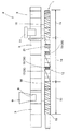
図1は、本発明の押出機用スクリュ1を組み込んだ2軸押出機2を模式的に示したものであり、図上部は押出機用スクリュ1とバレル3との位置関係を示すためのバレル3の側面図であり、図下部は該バレル3に収容される押出機用スクリュ1の側面図である。なお、以降の説明において、図1の左側(供給側)を上流側と呼び、図1の右側(排出側)を下流側と呼ぶ。
Hereinafter, an embodiment of a twin screw extruder provided with a screw for an extruder according to the present invention, a bearing segment used for the screw, and a screw for an extruder will be described.
FIG. 1 schematically shows a twin-
2軸押出機2は、内部に空洞部4を備えるバレル3と、該空洞部4に収容される左右一対の押出機用スクリュ1,1とを有している。該バレル3及び押出機用スクリュ1はそれぞれが複数のセグメントを軸方向に組み合わせて構成されている。該空洞部4は、図4に示すように横断面が一対の円を両者の中間で互いに円周の一部が重なり合うように重ねた形状(めがね孔状)にくり抜かれている。
バレル3の上流側には材料供給口8が形成されており、該材料供給口8にはホッパ9が接続されている。該ホッパ9を介して投入された被混練材料10は、該材料供給口8を通って空洞部4に供給される。該ホッパ9の下流側にあるバレル3には電気ヒーターや加熱した油を用いた加熱装置(図示せず)が設けられており、該バレル3から内部を通過する被混練材料10に熱が供給され、該被混練材料10を溶融状態または半溶融状態で搬送可能となっている。
The twin-
A
バレル3の下流側には主に脱揮の用途に用いられる開口部11が設けられており、該開口部11を介して空洞部4の内外が連通状態となっている。該開口部11は、空洞部4内を減圧状態として被混練材料10から水分などの揮発成分を脱揮するために、真空ポンプ等の吸引装置(図示略)に接続可能とされている。なお、該開口部11は、混練条件に合わせて適宜設けられるものであり、混練条件によっては設けられなかったり他の軸方向位置に設けられたり複数箇所に設けられたりする場合もある。
本発明の押出機用スクリュ1は、複数のセグメントを軸方向に組み合わして成るスクリュ本体12を有している。該スクリュ本体12は、互いに機能の異なるセグメントが組み合わされて、異なった機能を発揮する部分を軸方向に複数有している。本実施形態のスクリュ本体10においては、被混練材料10を下流側へ送る送り部13、被混練材料10を混練する混練部14、及び被混練材料10を加圧して押し出す押出部15が上流側から下流側に向けて設けられている。
An
The
送り部13は、送り用フライトを有するスクリュセグメント16を軸芯方向に連結して構成されている。スクリュセグメント16は回転中心Oを挟んで径方向で互いに反対向きに突出する一対のフライト(2条フライト)を有し、各々のフライトは軸心方向に螺旋状に捩じれている。スクリュセグメント16は、フライト間に形成された溝部に入り込んだ被混練材料10を、自身の回転に合わして下流側に搬送する機能を有している。
混練部14は被混練部材10を混練する混練用フライトを有する混練セグメント36を有しており、該混練セグメント36は本実施の形態においては8個のロータセグメント17と2個のニーディングディスクセグメント19で成る。
The
The kneading
ロータセグメント17は、軸方向に螺旋状にねじれた2条フライトを有し、該フライトの先端部とバレル3の内壁との間に形成されるチップクリアランスに被混練材料10を通過させて、被混練材料10に剪断力を与えながら混練を行っている。該ロータセグメント17は、そのフライトの先端部にチップクリアランスが小さい高位チップ部と高位チップ部よりチップクリアランスが大きい低位チップ部とが軸方向及び周方向に交互に出現するように形成されており、これらをフライトに設けることで被混練材料10に混練作用を付与して混練できるようになっている。
The
ニーディングディスクセグメント19は、厚さ0.1D1(D1:ニーディングディスクセグメント19の回転外径)の平板状の複数枚の混練用フライトを軸方向に互い違いに有している。該ニーディングディスクセグメント19は、チップクリアランスが上述のロータセグメント17より小さい2条翼タイプを採用している。このため、該ニーディングセグメント19を通過する被混練材料10は高い剪断力を受けて混練されることになる。
押出部15は、上記送り部13と同様なスクリュセグメント16を軸方向に連結して構成されているが、上記送り部13と異なる点は下流側にいくに従ってスクリュセグメント16の軸方向ピッチが徐々に狭くなっている点である。これによって、押出部15では下流側に向かう被混練材料10の送り出し速度が徐々に下がり、被混練材料10が空洞部4内に充満して加圧状態となる。
The
The extruding
混練部14の混練セグメント36は、チップクリアランスの小さなロータセグメント17及びニーディングセグメント19で構成されており、大きな剪断力を被混練材料10に付与できるように混練用フライトが形成されている。しかし、大きな剪断力の反力の影響を受けるスクリュ本体12には非常に大きな力学的負荷が加わり、そのためスクリュ本体12が撓みやすくなる。その結果、回転中のスクリュ本体12ではスクリュ本体12の回転軸がぶれて、該混練セグメント36の混練用フライトの先端部がバレル3の内壁に接触しやすくなる。そこで、本発明ではスクリュ本体12を撓まないように支持する軸受セグメント21を設けている。
The kneading
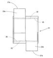
図2〜図4を用いて、軸受セグメント21について以下に詳しく説明する。
図2(a)、図2(b)は軸受セグメント21を軸方向から見た図(正面図)であり、図3は軸受セグメント21の側面図である。また、図4は軸受セグメント21とバレル3との関係を示す断面図である。
図4にあるように、軸受セグメント21、21は、左右一対のスクリュ軸22、22にそれぞれ噛み合い状態になるように取り付けられており、更に各々の軸受セグメント21は2つのフライト23a、23bを軸方向に組み合わして構成される。
The bearing
2A and 2B are views (front view) of the bearing
As shown in FIG. 4, the bearing
それぞれのフライト23a、23bには基端部にスクリュ軸22を挿入可能な軸孔25がそれぞれ形成されており、該軸孔25の内周面には軸方向に亘る複数の歯溝が回転方向Rに沿って形成された穴スプラインが設けられている。該スクリュ軸22には、軸孔25の歯溝に対応した歯を複数外周面に形成した軸スプラインが設けられており、該フライト23a、23bはスクリュ軸22の回転に合わせて回転方向Rに向かって一体回転可能となっている。
図2(a)にあるように、フライト23a、23bは、スクリュ本体12の回転軸心Oを中心として回転方向Rにそれぞれ均等(等角度の間隔)となるように位相をずらして配置されている。すなわち、本実施形態のようにフライトの軸方向の設置数が2枚である場合は180°位相をずらして設けられ、仮にフライトの設置数が3枚である場合は120°位相をずらして等角度の間隔となるよう設けられる。
Each of the
As shown in FIG. 2A, the
図2(a)乃至図4にあるように、フライト23a、23bは、径方向に伸びる板状に形成された1条ディスクであって、該軸受セグメント21の回転外径をDとした場合に、該ディスクの厚み(最大厚み)は軸方向に0.2D以上とされている。通常のニーディングディスクではディスクの厚みは0.1D以下であるが、このディスクを1条とし且つその厚みを0.2D以上とすることで、フライト23a、23bの先端部27a、27bがバレル3(空洞部4)の内壁面に対して有する対向面積を大きくすることができ、この大面積の先端部27a、27bに溶解した被混練材料10が膜状に広がって流体軸受としてスクリュ本体12を支持することが可能となる。
As shown in FIGS. 2A to 4, the
また、フライト23a、23bの先端部27a、27bの対向面積を大きくすることで、スクリュ本体12に軸方向と垂直方向に力が加わっても、該先端部27a、27bに加わる面圧を下げることができるようになる。そのため、先端部27a、27bに形成された膜状の被混練材料10が切れにくくなって、スクリュ回転中に流体軸受の機能を失うことなく、混練セグメント36のフライトやバレル3の内壁の摩耗を抑制することができるようになる。
フライト23a、23bは、断面形状がスクリュ軸22の軸心を頂点としてバレル3の内壁に向かって広がるように形成され、スクリュ本体12の回転軸心Oからもっとも離れた外周面には円弧状の先端部27a、27bが形成されている。該フライト23a、23bは、左右のいずれか一方の先端部27a、27bが絶えず他方のフライト23a及びフライト23bのフライトが形成されていない胴部周縁に対向する完全噛み合い型の断面形状となっている。軸受セグメント21のフライト23a、23bを完全噛み合い型とすることで、フライト23a、23b相互により被混練材料10が相互にかき取られセルフクリーニングされるようになり、被混練材料10に滞留及びそれに起因する材料変質が生じなくなる。その結果、滞留に起因するコンタミの発生が抑制される。
Further, by increasing the facing area of the
The
フライト23a、23bは、バレル3の内壁と先端部27a、27bとの間にそれぞれクリアランス部(チップクリアランス)28a、28bが形成されている。該クリアランス部28a、28bは、該先端部27a、27bとバレル3の内壁との間に形成された空間であり、最も狭い部分で0.004D2〜0.01D2(D2は混練セグメントの回転外径)となるように設定されているとともに軸受セグメント21の回転方向Rに沿って先端部27a、27bとバレル3の間隔が徐々に広がるように設定されている。これによって、該軸受セグメント21が回転すると回転方向Rに面した広い入り側から被混練材料10がクリアランス部28a、28bに容易に導入され、先端部27a、27bとバレル3の間隔が徐々に狭くなるに従ってこの導入された被混練材料10を先端部27a、27bとバレル3の間に隙間なく広げることができるようになり、該先端部27a、27bに被混練材料10の膜状物が形成されこの膜状に広がった被混練材料10が軸受セグメント21の流体軸受作用を発揮させる。
In the
またさらに、軸受セグメント21は、図2(b)に示すように、クリアランス部28a、28bをフライト23a、23bの先端部27a、27bとバレル3の内壁との間隔が一定となるように形成することもできる。この間隔は0.005D2〜0.02D2(D2は混練セグメントの回転外径)に設定するのが好ましく、これによって、被混練材料10がクリアランス部28a、28bの先端部27a、27bとバレル3の間に隙間なく広がり、この膜状に広がった被混練材料10が軸受セグメント21の流体軸受作用を発揮するようになる。
Furthermore, as shown in FIG. 2B, the bearing
なお、該混練セグメント36の回転外径は、前記軸受セグメント21の回転外径Dより小さく構成されていることが好ましい。言い替えれば、ロータセグメント17及びニーディングセグメント19のフライトの回転外径を該軸受セグメント21のフライト23a、23bの回転外径Dより小さくすることで、該混練セグメント36のフライトの先端部がバレル3の内壁に接触することをより確実に防止することができる。
本発明の押出機用スクリュ1は、上述した軸受セグメント21を異なる軸方向位置に設けることで、特に混練部14との位置関係を変えることで、複数の実施形態を得ることができる。
In addition, it is preferable that the rotational outer diameter of the kneading
The
つまり、本発明の押出機用スクリュ1は、図1〜図4及び図6に示すように軸受セグメント21が混練部14内に設けられる第1実施形態の押出機用スクリュ1、図7に示すように軸受セグメント21が混練部14から下流側に離れて設けられる第2実施形態の押出機用スクリュ1、または図8に示すように複数の混練部14が押出機用スクリュ1に備えられる場合に、複数の混練部のうち最も上流側に位置する第1混練部14a内に軸受セグメント21が設けられる第3実施形態の押出機用スクリュ1を有している。
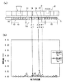
そこで、図5〜8を用いて第1〜第3実施形態に係る押出機用スクリュ1の軸受セグメント21の設置位置とスクリュ本体12の摩耗量との関係を詳しく説明する。なお、図5〜図8の上図(a)はいずれもスクリュ本体12を構成する各セグメントが軸方向にどのように連結されているかを示しており、下図(b)は各セグメント毎の摩耗量を軸方向位置に対して示したものである。
That is, the
Then, the relationship between the installation position of the bearing
該摩耗量は、被混練材料10(PP:ポリプロピレン)を2軸押出機に供給し、バレル3を200℃に加熱した状態で回転数300rpmで一定時間連続的に運転させた後に計測したものである。2軸押出機はスクリュ本体12(最大回転外径72mm、全長2m)をバレル3内に2軸備えている同方向回転型押出機である。
摩耗量は、運転前のスクリュ本体12の各セグメントの質量から運転後の各セグメントの質量を引いて、その値を運転前のスクリュ本体12の各セグメントの質量で割ったものである。該摩耗量は左右一対の押出機用スクリュ1、1のそれぞれ、つまり左側と右側の押出機用スクリュのそれぞれについて求められる。
The amount of wear was measured after supplying the material to be kneaded 10 (PP: polypropylene) to a twin-screw extruder and continuously operating at a rotation speed of 300 rpm for a fixed time with the
The amount of wear is obtained by subtracting the mass of each segment after operation from the mass of each segment of the screw
図5は軸受セグメント21を有していない従来の押出機用スクリュ29を図1と同様に模式的に示している。なお、従来の押出機用スクリュ29は、軸受セグメント21が設けられていないが、この点を除けば第1実施形態における押出機用スクリュ1と同種類のセグメントが同じ組み合わせで設けられている。
図5(a)のA1及びA2に設けられるニーディングセグメント19の摩耗量は、図5(b)のa1及びa2に示されるように0.25%以上となっており、混練部14のA1またはA2以外のセグメントにおいても摩耗量は殆どが0.05%以上となっている。これに対して、送り部13のセグメントや押出部15のセグメントでは摩耗量が0.05%以下と低い。このことから、従来の押出機用スクリュ29においては、軸方向のいずれかの位置に摩耗が発生していること、及び摩耗が特に混練部で生じやすいことが分かる。
FIG. 5 schematically shows a conventional screw 29 for an extruder that does not have a bearing
The amount of wear of the kneading
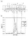
図6は、第1実施形態における押出機用スクリュ1を示している。該押出機用スクリュ1は混練部14に設けられた8個のロータセグメント17の7番目の後に図2(b)に示される軸受セグメント21が設けられている。該軸受セグメント21は混練部14に対応した位置(混練セグメント36のいずれかに隣接する位置)に設けられており、その軸方向位置は図6(a)においてB1で示され、その摩耗量は図6(b)においてb1で示される。
図6(a)のA1及びA2に設けられるニーディングセグメント19は、図6(b)のa1及びa2に示されるように、摩耗量が0.05%以下となっており、従来の押出機用スクリュ29のニーディングセグメント19の摩耗量より著しく低くなっていることが分かる。また、図6(b)の混練部14の摩耗量も0.05%以下となっており、混練部14のいずれの位置においても摩耗が従来の押出機用スクリュ29より抑制されていることが分かる。
FIG. 6 shows the
The kneading
このことから、軸受セグメント21を混練部14内に設けることで、スクリュ本体12の撓みが防止され、該軸受セグメント21の流体軸受作用により混練部14におけるフライト23a、23bやバレル3の内壁の摩耗を抑制することができる。
また、混練部14の軸方向長さは4.5D以上であり、軸受セグメント21は混練部14の上流端より下流側4.5D以上に設けられている。これによって、混練部14を通過する間に被混練材料10が十分に溶解・混練され、供給された被混練材料10がフライト23a、23bの先端部27a、27bとバレル3の内壁との間に入り込める程度まで溶解されるので、十分に溶解された被混練材料10により流体軸受効果を発揮させることができる。
Therefore, by providing the bearing
Moreover, the axial direction length of the kneading
図7(a)は、第2実施形態の押出機用スクリュ1を示している。該押出機用スクリュ1には、軸受セグメント21が混練部14の下流端からその下流側に向かって距離Sが3.0D以内(D:軸受セグメントの回転外径)となる位置、本実施形態では軸受セグメント21の下流端が混練部14の下流端より下流側3.0Dとなる位置に軸受セグメント21が設けられている。
第2実施形態の押出機用スクリュ1では、図7(a)のa1及びa2に示されるニーディングセグメント19の摩耗量は、第1実施形態の摩耗量(図6(b)のa1及びa2の摩耗量)よりは大きくなるものの、従来の押出機用スクリュ29の摩耗量(図5(b)のa1及びa2の摩耗量)よりは小さくなっている。また、本実施形態のニーディングセグメント19の摩耗量においては、軸受セグメント21に近い側のa2の摩耗量の方がa1より小さくなっている。
Fig.7 (a) has shown the
In the
このことから、軸受セグメント21を混練部14の下流端より下流側3.0D以内に設けることによっても、スクリュ本体12の撓みが防止され、混練部14におけるフライト23a、23bやバレル3の摩耗を抑制できることがわかる。
また、本実施形態においても、押出機用スクリュ1の混練部14は軸方向長さが4.5D以上であり、軸受セグメント21は混練部14の下流端より下流側3.0D以内であると共に混練部14の上流端より下流側4.5D以上の軸方向位置に設けられている。これによって、材料供給口8が混練部14のやや上流側に設けられた場合であっても、混練部14を通過する間に被混練材料10が十分に溶融・混練され、供給された被混練材料10がフライト23a、23bの先端部27a、27bとバレル3の内壁との間に入り込める程度まで融解された被混練材料10により流体軸受効果を発揮させることができる。
Therefore, by providing the bearing
Also in the present embodiment, the kneading
図8は、第3実施形態の押出機用スクリュ1を示したものである。該押出機用スクリュ1は第1送り部13a、第1混練部14aに続いて第2送り部13b、第2混練部14bを有しており、該第1混練部14aに対応する位置に軸受セグメント21が設けられている。
第3実施形態の押出機用スクリュ1においても、第1混練部14a及び第2混練部14bのニーディングセグメント19の摩耗量が第2実施形態のa1及びa2の摩耗量より小さくなることが確認されている。よって、本実施形態の押出機用スクリュ1のように、混練部14がスクリュ本体12の軸方向に複数かつ互いに離間して設けられる場合にあっては、軸方向に設けられる複数の混練部14のうちで最も上流側の第1混練部14aに少なくとも軸受セグメント21を設置するのがよいと判断される。これは、被混練材料10が上流側に位置するほど未溶融の割合が増して粘度が高くなる場合があるため、スクリュ本体12に及ぼされる力学的負荷が大きくなるからである。
FIG. 8 shows the
Also in the
上記実施形態の押出機用スクリュ1は反方向回転型の2軸押出機2にも用いることができる。該押出機用スクリュ1を備える2軸押出機2は、大きな剪断力で被混練材料10を混練できるものでありながら、スクリュ本体12やバレル3の摩耗を抑制することができ、2軸押出機2の耐久性を向上させることができる。
なお、上記実施の形態においては、混練セグメント36としてロータセグメント17及びニーディングディスクセグメント19を用いているが、少なくとも一方からなる混練セグメント36を用いればよく、組合せて用いる場合は組合せ個数を任意に設定することができる。また、ロータセグメント17としては、チップクリアランスが一定となるクリアランス部28a、28b(チップ部)を形成したものを用いることができる。
The
In the above-described embodiment, the
1 押出機用スクリュ
2 2軸押出機
3 バレル
10 押出機用スクリュ
12 スクリュ本体
14 混練部
16 スクリュセグメント
21 軸受セグメント
23 フライト
27 先端部
28 クリアランス部
DESCRIPTION OF
Claims (10)
前記被混練材料の混練を行っている際にスクリュ本体を中途部で支持する機能を備えた軸受セグメントが、前記混練部に対応する位置又は混練部より下流側に設けられており、
前記軸受セグメントは、1条完全噛合い型の断面形状を有するフライトを軸方向に少なくとも2つ以上備え、各フライトが回転方向にそれぞれ均等に位相をずらして配置されていて、前記各フライトの軸方向長さが0.2D以上(D:軸受セグメントの回転外径)に設定されていることを特徴とする押出機用スクリュ。 A screw body comprising a screw segment for conveying a material to be kneaded, a kneading segment having two or more kneading flights for kneading the material to be kneaded that has been conveyed by the screw segment, and a kneading part comprising the kneading segment. In the extruder screw provided,
A bearing segment having a function of supporting the screw main body in the middle part when kneading the material to be kneaded is provided at a position corresponding to the kneading part or downstream from the kneading part,
The bearing segment includes at least two flights having a single-engagement complete mesh type cross-sectional shape in the axial direction, and each flight is arranged with an equal phase shift in the rotation direction. A screw for an extruder, characterized in that the direction length is set to 0.2 D or more (D: rotating outer diameter of bearing segment).
前記第1混練部の軸方向長さが4.5D以上である場合に、
前記軸受セグメントが、第1混練部の上流端から下流側4.5D以上の距離に位置していることを特徴とする請求項1又は2に記載の押出機用スクリュ。 The kneading part is a first kneading part located on the most upstream side among a plurality of kneading parts provided apart from each other in the axial direction of the screw body,
When the axial length of the first kneading part is 4.5D or more,
The screw for an extruder according to claim 1 or 2, wherein the bearing segment is located at a distance of 4.5D or more downstream from the upstream end of the first kneading section.
該クリアランス部は、軸受セグメントの回転方向前方に向って先端部とバレルの内壁との間の間隔が徐々に広がるように設定されていることを特徴とする請求項3〜5のいずれか1項に記載の押出機用スクリュ。 In the flight of the bearing segment, a clearance portion is formed at a tip portion facing the inner wall of the barrel into which the screw body is inserted,
The clearance part is set so that the space | interval between a front-end | tip part and an inner wall of a barrel may spread gradually toward the rotation direction front of a bearing segment. The screw for an extruder according to 1.
前記混練部のうち最も上流側に位置する第1混練部に対応する位置に、請求項7又は8に記載の軸受セグメントが設けられていることを特徴とする押出機用スクリュ。 A screw segment for conveying the material to be kneaded, and a kneading segment having two or more kneading flights for kneading the material to be kneaded conveyed by the screw segment, and the kneading part comprising the kneading segment is axially A plurality of screw bodies provided apart from each other,
The screw for an extruder according to claim 7 or 8, wherein the bearing segment according to claim 7 or 8 is provided at a position corresponding to the first kneading section located on the most upstream side among the kneading sections.
Priority Applications (5)
| Application Number | Priority Date | Filing Date | Title |
|---|---|---|---|
| JP2007016361A JP4907366B2 (en) | 2007-01-26 | 2007-01-26 | Extruder screw, bearing segment used therefor, and twin screw extruder provided with extruder screw |
| US11/940,007 US8403554B2 (en) | 2007-01-26 | 2007-11-14 | Screw for extruder, bearing segment used in the same and twin screw extruder provided with screw for extruder |
| DE102007055764.9A DE102007055764B4 (en) | 2007-01-26 | 2007-12-11 | STORAGE SEGMENT, EXTRUDER NECK WITH SUCH A STORAGE SEGMENT AND DOUBLE SNAIL EXTRUDERS |
| IT000085A ITMI20080085A1 (en) | 2007-01-26 | 2008-01-21 | SCREW FOR EXTRUDER, BEARING SEGMENT USED FOR THE SAME, AND EXTRUDER WITH DOUBLE SCREW EQUIPPED WITH THIS EXTRUDER SCREW |
| CN200810003279.3A CN101259749B (en) | 2007-01-26 | 2008-01-28 | Screw for extruder, bearing segment and double-shaft extruder |
Applications Claiming Priority (1)
| Application Number | Priority Date | Filing Date | Title |
|---|---|---|---|
| JP2007016361A JP4907366B2 (en) | 2007-01-26 | 2007-01-26 | Extruder screw, bearing segment used therefor, and twin screw extruder provided with extruder screw |
Publications (2)
| Publication Number | Publication Date |
|---|---|
| JP2008183721A JP2008183721A (en) | 2008-08-14 |
| JP4907366B2 true JP4907366B2 (en) | 2012-03-28 |
Family
ID=39564071
Family Applications (1)
| Application Number | Title | Priority Date | Filing Date |
|---|---|---|---|
| JP2007016361A Active JP4907366B2 (en) | 2007-01-26 | 2007-01-26 | Extruder screw, bearing segment used therefor, and twin screw extruder provided with extruder screw |
Country Status (5)
| Country | Link |
|---|---|
| US (1) | US8403554B2 (en) |
| JP (1) | JP4907366B2 (en) |
| CN (1) | CN101259749B (en) |
| DE (1) | DE102007055764B4 (en) |
| IT (1) | ITMI20080085A1 (en) |
Families Citing this family (12)
| Publication number | Priority date | Publication date | Assignee | Title |
|---|---|---|---|---|
| DE102008048580B4 (en) * | 2008-09-23 | 2014-08-21 | List Holding Ag | Device for carrying out mechanical, chemical and / or thermal processes |
| DE102009059072A1 (en) * | 2009-12-18 | 2011-06-22 | Bayer Technology Services GmbH, 51373 | Screw elements for extruding viscoelastic masses |
| CN101879777A (en) * | 2010-06-12 | 2010-11-10 | 广东轻工职业技术学院 | Co-rotating non-uniform self-cleaning multi-screw plasticizing exhaust extrusion device and method |
| JP5693269B2 (en) * | 2011-02-02 | 2015-04-01 | 株式会社神戸製鋼所 | Kneading segment and kneading equipment |
| EP2842716B1 (en) * | 2013-08-29 | 2016-07-13 | Coperion GmbH | Worm machine and method for the treatment of plastic melts |
| JP6242232B2 (en) | 2014-02-13 | 2017-12-06 | 株式会社神戸製鋼所 | Continuous kneader |
| EP2965889A1 (en) | 2014-07-11 | 2016-01-13 | Covestro Deutschland AG | Mixing elements with improved dispersant effect |
| JP6735135B2 (en) * | 2016-04-20 | 2020-08-05 | 株式会社神戸製鋼所 | Screw type extruder |
| JP7034422B2 (en) * | 2018-02-13 | 2022-03-14 | 株式会社日本製鋼所 | Two-screw extruder, reducer and extrusion method |
| CN111391274B (en) * | 2020-03-25 | 2022-04-05 | 五邑大学 | A kind of anisotropic differential rotating extrusion device, extruder and material production method |
| CN116020338B (en) * | 2023-02-24 | 2025-12-23 | 厦门环塑源新材料科技有限公司 | A twin-screw extruder for biodegradable materials |
| CN121468920A (en) * | 2026-01-08 | 2026-02-06 | 四川中旺科技有限公司 | A twin-screw extruder for lithium battery separator plastics |
Family Cites Families (65)
| Publication number | Priority date | Publication date | Assignee | Title |
|---|---|---|---|---|
| USRE26147E (en) * | 1967-01-24 | Parshall et | ||
| US2670188A (en) * | 1949-09-23 | 1954-02-23 | Bayer Ag | Mixing and kneading machine |
| USRE23880E (en) * | 1950-03-07 | 1954-09-28 | Extruder | |
| US2744287A (en) * | 1952-09-24 | 1956-05-08 | Us Rubber Co | Mill |
| US2910726A (en) * | 1957-08-20 | 1959-11-03 | Us Rubber Co | Pelletizing apparatus |
| CA836936A (en) * | 1962-03-21 | 1970-03-17 | A. Loomans Bernard | Continuous mixer |
| US3335461A (en) * | 1964-06-12 | 1967-08-15 | Lester Engineering Co | Reciprocating screw injection molding machine |
| US3287477A (en) * | 1964-11-12 | 1966-11-22 | Koppers Co Inc | Process and apparatus for extruding a foamed plastic |
| GB1132898A (en) * | 1965-08-13 | 1968-11-06 | Werner & Pfleiderer | Multi-stage screw treatment device |
| CH445457A (en) * | 1966-02-11 | 1967-10-31 | Werner & Pfleiderer | Mixing or kneading machine |
| JPS5149661Y1 (en) * | 1966-06-06 | 1976-11-30 | ||
| US3486192A (en) * | 1967-03-24 | 1969-12-30 | Union Carbide Corp | Apparatus for extrusion of thermoplastics |
| GB1223275A (en) * | 1967-04-05 | 1971-02-24 | Kanegafuchii Kagaku Kogyo Kabu | Improvements in and relating to extruders |
| DE1679884B2 (en) * | 1967-12-16 | 1971-08-26 | Werner & Pfleiderer | MULTIPLE SHAFT CONTINUOUSLY WORKING MIXER AND MIXING MACHINE FOR PLASTIC MACHINE |
| US3814563A (en) * | 1969-02-25 | 1974-06-04 | French Oil Mill Machinery | Apparatus for treating elastomeric materials |
| US3618902A (en) * | 1969-11-14 | 1971-11-09 | Teledyne Inc | Continuous mixer |
| DE2019522C3 (en) * | 1970-04-22 | 1975-08-07 | Windmoeller & Hoelscher, 4540 Lengerich | Screw press for thermoplastics and non-crosslinked elastomers |
| DE2043833B2 (en) * | 1970-09-04 | 1972-03-09 | Fa. Werner & Pfleiderer, 7000 Stuttgart | SCREW EXTRUSION PRESS FOR THE PROCESSING AND TREATMENT OF MELTS OF PLASTIC MATERIALS, PLASTIC POWDER AND GRANU LATEN |
| US3685804A (en) * | 1970-10-26 | 1972-08-22 | Sterling Extruder Corp | Mixing apparatus and method |
| DE2107927B1 (en) * | 1971-02-19 | 1972-07-20 | Fa Werner & Pfleiderer | Process for the continuous preparation and granulation of thermosetting molding compounds |
| US3719350A (en) * | 1971-03-22 | 1973-03-06 | Baker Perkins Inc | Self-cleaning venting section for continuous mixers |
| US3981658A (en) * | 1972-01-14 | 1976-09-21 | International Basic Economy Corporation | Screw type apparatus for drying moist polymeric materials |
| US3881708A (en) * | 1972-06-15 | 1975-05-06 | Usm Corp | Mixing extruders |
| DE2245570A1 (en) * | 1972-09-16 | 1974-04-04 | Krupp Gmbh | SCREW EXTRUDER |
| US3884452A (en) * | 1972-09-25 | 1975-05-20 | Manbritt Ind Inc | Blow-molding plasticizing manifold |
| US3823921A (en) * | 1972-11-14 | 1974-07-16 | Teledyne Inc | Continuous processor for treating material |
| US4110843A (en) * | 1973-02-23 | 1978-08-29 | Welding Engineers, Inc. | Pressure restricting means for a liquid outlet of an extruder |
| JPS5111882A (en) * | 1974-07-20 | 1976-01-30 | Sumitomo Chemical Co | Mihannotanryotaio jokyosuruhoho |
| US4099897A (en) * | 1975-11-04 | 1978-07-11 | Hitachi Cable, Ltd. | Apparatus for producing foamed plastic insulated wires |
| US4118164A (en) * | 1977-07-15 | 1978-10-03 | Wenger Manufacturing | High-output apparatus for producing dense, uniformly layered meat analogue product |
| US4184773A (en) * | 1977-08-11 | 1980-01-22 | Usm Corporation | Mixer rotor with a shear edge |
| US4408887A (en) * | 1981-12-07 | 1983-10-11 | Kishihiro Yamaoka | Continuous kneader |
| US4875847A (en) * | 1984-04-23 | 1989-10-24 | Wenger Manufacturing, Inc. | Twin-screw extruder having respective conical nose screw sections |
| JPS6219074A (en) * | 1985-07-17 | 1987-01-27 | Tech Res Assoc Extru Cook Food Ind | Method of extrusion processing of food ingredient and device therefor |
| DE3615586C1 (en) * | 1986-05-09 | 1987-05-07 | Berstorff Gmbh Masch Hermann | Extrusion device for the production of plastic melt mixtures |
| US4744669A (en) * | 1986-10-23 | 1988-05-17 | Baker Perkins, Inc. | Mixing and extruding apparatus and methods |
| US4752135A (en) * | 1986-12-01 | 1988-06-21 | Baker Perkins, Inc. | Mixing apparatus and methods |
| US4779989A (en) * | 1986-12-01 | 1988-10-25 | Barr Robert A | Transfer mixer assembly for use with an extruder screw of a polymer extruder or the like |
| US4842414A (en) * | 1987-09-16 | 1989-06-27 | Dray Robert F | Mixing device for a feed screw |
| GB8804313D0 (en) * | 1988-02-24 | 1988-03-23 | Apv Plc | Improvements in/relating to mixers |
| GB8808107D0 (en) * | 1988-04-07 | 1988-05-11 | Meyer P | Method & means for improving uniformity-performance of cold feed rubber extruders |
| JP2578479B2 (en) * | 1988-07-26 | 1997-02-05 | 帝人株式会社 | Method for producing polymer containing powder additive |
| US5129729A (en) * | 1990-12-20 | 1992-07-14 | Paul Geyer | Extrusion apparatus for mixing and extruding of thermo-plastic and thermo-setting materials |
| JPH0677679B2 (en) * | 1991-07-29 | 1994-10-05 | ビーエイチ工業有限会社 | Continuous kneading machine |
| JP2915705B2 (en) * | 1991-11-25 | 1999-07-05 | 三菱重工業株式会社 | Manufacturing method of screw for molding machine |
| US5332314A (en) * | 1992-07-06 | 1994-07-26 | Paul Geyer | Extrusion apparatus with a backfeed extruder for mixing and extruding of thermo-plastic and thermo-setting materials |
| US5348388A (en) * | 1992-09-15 | 1994-09-20 | Paul Geyer | Extrusion apparatus for mixing and extruding thermo-plastic materials |
| US5352539A (en) * | 1992-10-27 | 1994-10-04 | Friedrich Theysohn Gmbh | Extruder housing for double-screw extruder having an annularly stepped internal bore covered by a hot isostatically-pressed structure, and method of making same |
| JP3113879B2 (en) * | 1993-07-12 | 2000-12-04 | 中央化学株式会社 | Continuous kneading extruder |
| US5573332A (en) * | 1993-09-02 | 1996-11-12 | Werner & Pfleiderer Gmbh | Screw element for a screw-like extrusion machine |
| JP2530417B2 (en) * | 1993-11-10 | 1996-09-04 | 株式会社佐藤鉄工所 | Vacuum extrusion molding method and apparatus |
| US5641227A (en) * | 1995-04-27 | 1997-06-24 | Geyer; Paul | Extrusion and refining apparatus and method |
| US5965173A (en) * | 1995-05-31 | 1999-10-12 | Goldup; Frederick H. | Plasticating apparatus and screw therefor |
| JP3472391B2 (en) * | 1995-07-19 | 2003-12-02 | 東芝機械株式会社 | Twin screw extruder and extrusion method using the twin screw extruder |
| US5573331A (en) * | 1995-09-08 | 1996-11-12 | Lin; Ping H. | Multiple-stage screw for blending materials |
| JP3373154B2 (en) * | 1998-06-09 | 2003-02-04 | 住友ベークライト株式会社 | Single-shaft continuous kneader |
| US6116770A (en) * | 1998-10-02 | 2000-09-12 | Krupp Werner & Pfleiderer Corporation | Mixing element for screw extruder |
| DE19860256A1 (en) * | 1998-12-24 | 2000-06-29 | Krupp Werner & Pfleiderer Gmbh | Two-shaft extruder |
| US6170975B1 (en) * | 1999-02-08 | 2001-01-09 | Krupp Werner & Pfleiderer | Multi-shaft extruder kneading discs, kneading disc blocks and extruder |
| JP2000296517A (en) * | 1999-04-15 | 2000-10-24 | Japan Steel Works Ltd:The | Kneading screw piece |
| JP3798595B2 (en) * | 2000-01-25 | 2006-07-19 | 株式会社神戸製鋼所 | Kneading rotor, screw set and twin screw extruder |
| WO2002009919A2 (en) * | 2000-07-31 | 2002-02-07 | Babu Padmanabhan | Fractional and higher lobed co-rotating twin-screw elements |
| JP3656957B2 (en) * | 2001-01-16 | 2005-06-08 | 株式会社神戸製鋼所 | Biaxial continuous kneader and kneading method using the same |
| JP4252016B2 (en) * | 2004-06-21 | 2009-04-08 | 株式会社神戸製鋼所 | Extruder |
| JP4782507B2 (en) * | 2004-10-26 | 2011-09-28 | 住友化学株式会社 | Method for producing thermoplastic elastomer composition |
-
2007
- 2007-01-26 JP JP2007016361A patent/JP4907366B2/en active Active
- 2007-11-14 US US11/940,007 patent/US8403554B2/en not_active Expired - Fee Related
- 2007-12-11 DE DE102007055764.9A patent/DE102007055764B4/en active Active
-
2008
- 2008-01-21 IT IT000085A patent/ITMI20080085A1/en unknown
- 2008-01-28 CN CN200810003279.3A patent/CN101259749B/en active Active
Also Published As
| Publication number | Publication date |
|---|---|
| US20080181051A1 (en) | 2008-07-31 |
| DE102007055764A1 (en) | 2008-07-31 |
| CN101259749B (en) | 2015-07-01 |
| US8403554B2 (en) | 2013-03-26 |
| ITMI20080085A1 (en) | 2008-07-27 |
| CN101259749A (en) | 2008-09-10 |
| JP2008183721A (en) | 2008-08-14 |
| DE102007055764B4 (en) | 2019-01-24 |
Similar Documents
| Publication | Publication Date | Title |
|---|---|---|
| JP4907366B2 (en) | Extruder screw, bearing segment used therefor, and twin screw extruder provided with extruder screw | |
| JP5137613B2 (en) | Kneading disc segment and twin screw extruder | |
| CN101541494B (en) | Kneading screw, biaxial extruder and method for assembling kneading screw | |
| US6136246A (en) | Screw extruder with improved dispersive mixing elements | |
| US6170975B1 (en) | Multi-shaft extruder kneading discs, kneading disc blocks and extruder | |
| EP2484505B1 (en) | Kneading segment and kneading equipment | |
| US11273420B2 (en) | Extruder screw, extrusion device having an extruder screw and method for plasticizing a plastic | |
| JP2002210731A (en) | Biaxial continuous kneader and kneading method using it | |
| US9090013B2 (en) | Dual screw extrusion apparatus having a mixing chamber and a conveying chamber downstream thereof with the mixing chamber having a wall clearance greater than that of the conveying chamber | |
| EP1148987B1 (en) | Multi-shaft extruder screw bushing and extruder | |
| CN101400500B (en) | Screw element | |
| JP4834653B2 (en) | Kneading screw and extruder | |
| US20030206482A1 (en) | Extrusion screw tip | |
| JP5679874B2 (en) | Twin screw extruder | |
| JPS61242822A (en) | Two-axial extruding machine | |
| CN220143093U (en) | Double-rotor mixing mechanism and mixer | |
| US6059440A (en) | Twin-screw extruder | |
| CN100374280C (en) | Plastifying screw for an extruder or a forcing machine, having a narrower thread width in the transition region | |
| EP3446850A1 (en) | Screw-type extruder | |
| JP2024022510A (en) | Processing elements for processing materials using screw machines | |
| JPS61244521A (en) | Two-shaft extruder | |
| JP2009286097A (en) | Screw and manufacturing process for molding |
Legal Events
| Date | Code | Title | Description |
|---|---|---|---|
| A621 | Written request for application examination |
Free format text: JAPANESE INTERMEDIATE CODE: A621 Effective date: 20090929 |
|
| A977 | Report on retrieval |
Free format text: JAPANESE INTERMEDIATE CODE: A971007 Effective date: 20111208 |
|
| TRDD | Decision of grant or rejection written | ||
| A01 | Written decision to grant a patent or to grant a registration (utility model) |
Free format text: JAPANESE INTERMEDIATE CODE: A01 Effective date: 20120110 |
|
| A01 | Written decision to grant a patent or to grant a registration (utility model) |
Free format text: JAPANESE INTERMEDIATE CODE: A01 |
|
| A61 | First payment of annual fees (during grant procedure) |
Free format text: JAPANESE INTERMEDIATE CODE: A61 Effective date: 20120111 |
|
| FPAY | Renewal fee payment (event date is renewal date of database) |
Free format text: PAYMENT UNTIL: 20150120 Year of fee payment: 3 |
|
| R150 | Certificate of patent or registration of utility model |
Ref document number: 4907366 Country of ref document: JP Free format text: JAPANESE INTERMEDIATE CODE: R150 Free format text: JAPANESE INTERMEDIATE CODE: R150 |