JP4252016B2 - Extruder - Google Patents
Extruder Download PDFInfo
- Publication number
- JP4252016B2 JP4252016B2 JP2004182905A JP2004182905A JP4252016B2 JP 4252016 B2 JP4252016 B2 JP 4252016B2 JP 2004182905 A JP2004182905 A JP 2004182905A JP 2004182905 A JP2004182905 A JP 2004182905A JP 4252016 B2 JP4252016 B2 JP 4252016B2
- Authority
- JP
- Japan
- Prior art keywords
- kneading
- segment
- devolatilization
- downstream side
- flight
- Prior art date
- Legal status (The legal status is an assumption and is not a legal conclusion. Google has not performed a legal analysis and makes no representation as to the accuracy of the status listed.)
- Expired - Lifetime
Links
Images

Classifications
-
- B—PERFORMING OPERATIONS; TRANSPORTING
- B29—WORKING OF PLASTICS; WORKING OF SUBSTANCES IN A PLASTIC STATE IN GENERAL
- B29C—SHAPING OR JOINING OF PLASTICS; SHAPING OF MATERIAL IN A PLASTIC STATE, NOT OTHERWISE PROVIDED FOR; AFTER-TREATMENT OF THE SHAPED PRODUCTS, e.g. REPAIRING
- B29C48/00—Extrusion moulding, i.e. expressing the moulding material through a die or nozzle which imparts the desired form; Apparatus therefor
- B29C48/25—Component parts, details or accessories; Auxiliary operations
- B29C48/36—Means for plasticising or homogenising the moulding material or forcing it through the nozzle or die
- B29C48/50—Details of extruders
- B29C48/76—Venting, drying means; Degassing means
- B29C48/765—Venting, drying means; Degassing means in the extruder apparatus
- B29C48/766—Venting, drying means; Degassing means in the extruder apparatus in screw extruders
- B29C48/767—Venting, drying means; Degassing means in the extruder apparatus in screw extruders through a degassing opening of a barrel
-
- B—PERFORMING OPERATIONS; TRANSPORTING
- B29—WORKING OF PLASTICS; WORKING OF SUBSTANCES IN A PLASTIC STATE IN GENERAL
- B29B—PREPARATION OR PRETREATMENT OF THE MATERIAL TO BE SHAPED; MAKING GRANULES OR PREFORMS; RECOVERY OF PLASTICS OR OTHER CONSTITUENTS OF WASTE MATERIAL CONTAINING PLASTICS
- B29B7/00—Mixing; Kneading
- B29B7/30—Mixing; Kneading continuous, with mechanical mixing or kneading devices
- B29B7/34—Mixing; Kneading continuous, with mechanical mixing or kneading devices with movable mixing or kneading devices
- B29B7/38—Mixing; Kneading continuous, with mechanical mixing or kneading devices with movable mixing or kneading devices rotary
- B29B7/46—Mixing; Kneading continuous, with mechanical mixing or kneading devices with movable mixing or kneading devices rotary with more than one shaft
- B29B7/48—Mixing; Kneading continuous, with mechanical mixing or kneading devices with movable mixing or kneading devices rotary with more than one shaft with intermeshing devices, e.g. screws
- B29B7/488—Parts, e.g. casings, sealings; Accessories, e.g. flow controlling or throttling devices
- B29B7/489—Screws
-
- B—PERFORMING OPERATIONS; TRANSPORTING
- B29—WORKING OF PLASTICS; WORKING OF SUBSTANCES IN A PLASTIC STATE IN GENERAL
- B29B—PREPARATION OR PRETREATMENT OF THE MATERIAL TO BE SHAPED; MAKING GRANULES OR PREFORMS; RECOVERY OF PLASTICS OR OTHER CONSTITUENTS OF WASTE MATERIAL CONTAINING PLASTICS
- B29B7/00—Mixing; Kneading
- B29B7/74—Mixing; Kneading using other mixers or combinations of mixers, e.g. of dissimilar mixers ; Plant
- B29B7/7476—Systems, i.e. flow charts or diagrams; Plants
- B29B7/7495—Systems, i.e. flow charts or diagrams; Plants for mixing rubber
-
- B—PERFORMING OPERATIONS; TRANSPORTING
- B29—WORKING OF PLASTICS; WORKING OF SUBSTANCES IN A PLASTIC STATE IN GENERAL
- B29B—PREPARATION OR PRETREATMENT OF THE MATERIAL TO BE SHAPED; MAKING GRANULES OR PREFORMS; RECOVERY OF PLASTICS OR OTHER CONSTITUENTS OF WASTE MATERIAL CONTAINING PLASTICS
- B29B7/00—Mixing; Kneading
- B29B7/80—Component parts, details or accessories; Auxiliary operations
- B29B7/84—Venting or degassing ; Removing liquids, e.g. by evaporating components
- B29B7/845—Venting, degassing or removing evaporated components in devices with rotary stirrers
-
- B—PERFORMING OPERATIONS; TRANSPORTING
- B29—WORKING OF PLASTICS; WORKING OF SUBSTANCES IN A PLASTIC STATE IN GENERAL
- B29C—SHAPING OR JOINING OF PLASTICS; SHAPING OF MATERIAL IN A PLASTIC STATE, NOT OTHERWISE PROVIDED FOR; AFTER-TREATMENT OF THE SHAPED PRODUCTS, e.g. REPAIRING
- B29C48/00—Extrusion moulding, i.e. expressing the moulding material through a die or nozzle which imparts the desired form; Apparatus therefor
- B29C48/03—Extrusion moulding, i.e. expressing the moulding material through a die or nozzle which imparts the desired form; Apparatus therefor characterised by the shape of the extruded material at extrusion
- B29C48/04—Particle-shaped
-
- B—PERFORMING OPERATIONS; TRANSPORTING
- B29—WORKING OF PLASTICS; WORKING OF SUBSTANCES IN A PLASTIC STATE IN GENERAL
- B29C—SHAPING OR JOINING OF PLASTICS; SHAPING OF MATERIAL IN A PLASTIC STATE, NOT OTHERWISE PROVIDED FOR; AFTER-TREATMENT OF THE SHAPED PRODUCTS, e.g. REPAIRING
- B29C48/00—Extrusion moulding, i.e. expressing the moulding material through a die or nozzle which imparts the desired form; Apparatus therefor
- B29C48/25—Component parts, details or accessories; Auxiliary operations
- B29C48/36—Means for plasticising or homogenising the moulding material or forcing it through the nozzle or die
- B29C48/395—Means for plasticising or homogenising the moulding material or forcing it through the nozzle or die using screws surrounded by a cooperating barrel, e.g. single screw extruders
- B29C48/40—Means for plasticising or homogenising the moulding material or forcing it through the nozzle or die using screws surrounded by a cooperating barrel, e.g. single screw extruders using two or more parallel screws or at least two parallel non-intermeshing screws, e.g. twin screw extruders
- B29C48/402—Means for plasticising or homogenising the moulding material or forcing it through the nozzle or die using screws surrounded by a cooperating barrel, e.g. single screw extruders using two or more parallel screws or at least two parallel non-intermeshing screws, e.g. twin screw extruders the screws having intermeshing parts
Landscapes
- Engineering & Computer Science (AREA)
- Mechanical Engineering (AREA)
- Processing And Handling Of Plastics And Other Materials For Molding In General (AREA)
- Extrusion Moulding Of Plastics Or The Like (AREA)
Description
本発明は、プラスチックやゴム等の材料から効率よく揮発分を脱揮するのに適した押出機に関するものである。 The present invention relates to an extruder suitable for efficiently removing volatile components from materials such as plastic and rubber.
一般に、プラスチックコンパウンド等の複合樹脂材料は、連続混練機のバレル体内に高分子樹脂よりなる材料や粉体状の添加物を供給し、バレル体内に挿通された混練スクリュー体によってを両者を混練しながら下流側へ押し出すことで製造される。さらに、連続混練機の下流側に設置された造粒装置等によって、前記複合樹脂材料はペレット状に成形されたりする。
前記連続混練機には、混練スクリュー体が単軸のものや2軸のものがある。
2軸連続混練機は、互いに連通する左右一対の混練室を内部に有するバレル体と、混練室内に回転自在に挿通された左右一対の混練スクリュー体と、混練室内に材料を供給すべくバレル体の上流側に接続された供給手段を備えている。
In general, a composite resin material such as a plastic compound supplies a material made of a polymer resin or a powdery additive into the barrel of a continuous kneader, and kneads them together by a kneading screw inserted through the barrel. However, it is manufactured by extruding to the downstream side. Further, the composite resin material may be formed into a pellet shape by a granulator installed on the downstream side of the continuous kneader.
The continuous kneader includes a single kneading screw body and a biaxial one.
The biaxial continuous kneader includes a barrel body having a pair of left and right kneading chambers communicating with each other, a pair of left and right kneading screw bodies rotatably inserted into the kneading chamber, and a barrel body for supplying materials into the kneading chamber. Supply means connected to the upstream side.
混練スクリュー体は、材料を下流側に搬送するためのスクリューセグメントや、材料に高い剪断力を付与しつつ材料を練り込むようにするロータセグメントやニーディングセグメントが軸芯方向に連なるように接続されている。
特許文献1に記載された2軸連続混練機も前述の構成を備えたものであって、成分調整の目的で材料から強制的に揮発分や水分を取り除くべく、真空吸引用の開口(真空ベント)を備えているものとなっている。真空ベントから吸気することで混練室内を負圧とし、材料の脱揮を促進すると共に真空ベントを介して強制的に揮発分を外部に導出するようになっている。
The kneading screw body is connected so that the screw segment for conveying the material downstream, and the rotor segment and kneading segment for kneading the material while applying high shearing force to the material are connected in the axial direction. ing.
The biaxial continuous kneader described in Patent Document 1 is also provided with the above-described configuration, and an opening for vacuum suction (vacuum vent) is used to forcibly remove volatile components and moisture from the material for the purpose of component adjustment. ). By sucking air from the vacuum vent, the inside of the kneading chamber is set to a negative pressure to promote the devolatilization of the material and forcibly lead out volatile matter to the outside through the vacuum vent.
なお、2軸連続混練機自体で材料の押し出し機能を備えたものは、一般に2軸押出機と呼ばれている。
しかしながら、特許文献1に開示された技術では、真空ベントから吸気されることにより生じている混練室内の負圧状態は、専ら材料(被混練材)を下流側へ搬送するために設けられたスクリューセグメントの範囲に限定して生じるものとなっていたため、材料の脱揮が十分にできないといった問題が生じていた。
そこで、本発明は、材料からの効果的な脱揮が行えるようにした押出機を提供することを目的とする。
However, in the technique disclosed in Patent Document 1, the negative pressure state in the kneading chamber caused by suction from the vacuum vent is a screw provided exclusively for conveying the material (material to be kneaded) downstream. The problem was that the material could not be volatilized sufficiently because it was limited to the segment range.
Then, an object of this invention is to provide the extruder which enabled it to perform the effective devolatilization from material.
前記目的を達成するため、本発明においては以下の技術的手段を講じた。
すなわち、本発明における課題解決のための技術的手段は、混練室を内部に有するバレル体と、複数のセグメントからなると共に前記混練室内に回転自在に挿通され且つ回転することで材料を混練しつつ上流側から下流側へ送る混練スクリュー体とを有する押出機において、前記混練スクリュー体には、材料を下流側に移送可能なように捩れた混練フライトを有すると共にこの混練フライトで材料を下流側に送りつつ練り混ぜて揮発分を分離する脱揮セグメント部が備えられ、前記バレル体には、当該脱揮セグメント部が挿通している混練室に通じる真空吸引用の開口が設けられ、前記脱揮セグメント部の上流側及び前記開口の下流側のそれぞれに、材料が混練室内に充満する充満部が設けられていることを特徴とする。
In order to achieve the above object, the present invention takes the following technical means.
That is, the technical means for solving the problem in the present invention is that the material is kneaded by rotating the barrel body having a kneading chamber therein and a plurality of segments, and being rotatably inserted into the kneading chamber and rotating. In an extruder having a kneading screw body fed from the upstream side to the downstream side, the kneading screw body has a kneading flight twisted so that the material can be transferred to the downstream side, and the material is moved downstream by this kneading flight. A devolatilizing segment for separating volatile components by mixing while feeding is provided, and the barrel body is provided with an opening for vacuum suction leading to a kneading chamber through which the devolatilizing segment is inserted, and the devolatilization Filling portions for filling the material into the kneading chamber are provided on the upstream side of the segment portion and the downstream side of the opening, respectively.
この技術的手段によれば、混練スクリュー体の脱揮セグメント部がその上流側および下流側にある充満部により圧力シールされるため、当該脱揮セグメント部の負圧状態が確実に維持されるようになる。ゆえに、材料から蒸発した揮発成分は、当該脱揮セグメント部が挿通している真空吸引用の開口を介して確実に外部に排出され、材料の効果的な脱揮が行える。
換言すれば、本発明は、充満部で気密性を保持された混練室内に、材料を下流側に送る方向に捩れた混練フライトを備える脱揮セグメント部を設けたものである。ゆえに、かかる脱揮セグメント部は、混練フライトで材料を下流側に送りつつ練り混ぜて、材料の表面更新を行い、さらに当該表面更新による揮発分の分離を促進するような作用効果を奏するものとなっている。
According to this technical means, the devolatilization segment portion of the kneading screw body is pressure-sealed by the filling portions on the upstream side and the downstream side thereof, so that the negative pressure state of the devolatilization segment portion is reliably maintained. become. Therefore, the volatile component evaporated from the material is surely discharged to the outside through the vacuum suction opening through which the devolatilization segment portion is inserted, and the material can be effectively devolatilized.
In other words, according to the present invention, a devolatilization segment portion provided with a kneading flight twisted in a direction in which the material is sent to the downstream side is provided in a kneading chamber that is kept airtight in a filled portion. Therefore, such a devolatilization segment portion has the effect of promoting the separation of volatile components by renewing the surface of the material by kneading while sending the material downstream in the kneading flight, renewing the surface of the material, and further. It has become.
加えて、脱揮セグメント部には、戻し方向に捩れた形状のフライトが設けられていないため、脱揮セグメント部自体に材料の充満する部分がなく、混練室の広い(長い)範囲において負圧状態とすることが可能となる。したがって、表面更新により脱揮が促進される部分を真空吸引するための負圧領域として最大限に利用することができるため、効果的な脱揮を行うことができる。
好ましくは、前記充満部の下流側には、下流側へ送られる材料の流れに対して抵抗となる抵抗体が設けられ、この抵抗体により、前記充満部に材料が充満し気密性が保たれるようにするとよい。
In addition, since the devolatilization segment part is not provided with a flight with a twisted shape in the return direction, the devolatilization segment part itself has no material-filled part, and the negative pressure in a wide (long) range of the kneading chamber It becomes possible to be in a state. Therefore, since the part where devolatilization is promoted by the surface renewal can be utilized to the maximum as a negative pressure region for vacuum suction, effective devolatilization can be performed.
Preferably, on the downstream side of the filling portion, a resistor is provided that resists the flow of the material sent to the downstream side, and the resistor fills the filling portion with the material and maintains airtightness. It is good to make it.
なお、前記抵抗体は、材料を上流側へ押し戻す方向に捩れたフライトを有するセグメントからなるとよい。
こうすることで、抵抗体を構成するセグメント(スクリューセグメントやロータセグメント)のフライトは、材料を上流側に移送可能な逆ネジ状態で捩れているため、上流側から移送されてきた材料はこの部分で滞留し、当該抵抗体の上流側に材料の充満率の高い充満部が形成され、かかる充満部の前後空間(上流側空間と下流側空間)を圧力的に確実に遮断でき、隣接する脱揮セグメント部を確実にシールすることが可能となる。
In addition, the said resistor is good to consist of a segment which has the flight twisted in the direction which pushes back material upstream.
By doing so, the flight of the segment (screw segment or rotor segment) constituting the resistor is twisted in a reverse screw state that can transfer the material to the upstream side, so the material transferred from the upstream side is this part. And a filled portion with a high filling rate of the material is formed on the upstream side of the resistor, and the space before and after the filled portion (the upstream space and the downstream space) can be reliably shut off in pressure, and the adjacent removal It is possible to securely seal the volatile segment.
前記抵抗体は、材料を外部に排出すると共に材料が流入した際に流路抵抗を発生する排出部材からなるとよい。
これにより、上流側から移送されてきた材料は、流路抵抗の大きいダイス、オリフィス、移送配管及び濾過装置などの排出部材で流路抵抗を受け、排出部材の上流側で充満部を形成する。かかる充満部は、前後空間(上流側空間と下流側空間)を圧力的に確実に遮断でき、隣接する脱揮セグメント部を確実にシールすることが可能となる。
また、本発明における課題解決のための技術的手段は、前記脱揮セグメント部は、径方向で互いに反対向きに突出する一対の混練フライトを備えた2条翼ロータセグメントからなり、前記混練室内壁への材料の薄膜形成とその掻き取りをすることで材料からの揮発分の分離を促進させるべく、前記混練フライトの先端部には、材料の薄膜形成が可能となるように混練室内壁とのチップクリアランスが大きく設定された低位チップ部と、前記薄膜を掻き取り可能なように混練室内壁とのチップクリアランスが小さく設定されている高位チップ部とが形成されていることを特徴とする。
The resistor may be a discharge member that discharges the material to the outside and generates flow resistance when the material flows in.
As a result, the material transferred from the upstream side is subjected to flow path resistance by the discharge member such as a die, orifice, transfer pipe, and filtration device having a large flow path resistance, and forms a full portion on the upstream side of the discharge member. Such a filling portion can reliably block the front and rear spaces (upstream space and downstream space) in pressure and can reliably seal adjacent devolatilization segment portions.
Further, the technical means for solving the problem in the present invention is that the devolatilization segment portion is composed of a two-blade rotor segment having a pair of kneading flights protruding in opposite directions in the radial direction, and the kneading chamber inner wall In order to promote separation of volatile components from the material by forming a thin film of the material and scraping the material, the tip of the kneading flight is provided with a kneading chamber wall so that a thin film of the material can be formed. A low-order tip portion having a large tip clearance and a high-order tip portion having a small tip clearance from the kneading chamber wall so that the thin film can be scraped off are formed.
この技術的手段によれば、2条翼ロータセグメントの低位チップ部で、材料を混練室の内面に材料の薄膜を形成すると共に、高位チップ部で前記薄膜を掻き取ることで、材料の表面更新を反復して行い脱揮をさらに効果的に促進することができる。
なお好ましくは、前記バレル体の内部には互いに連通する一対の混練室が設けられており、前記混連室のそれぞれに混練スクリュー体が同方向に回転自在であるように挿通され、両混練スクリュー体は互いに噛み合うように配置するとよい。
また、前記脱揮セグメント部は、混練スクリュー体の軸芯方向で隣り合う各セグメントが、それぞれに備えられたフライトの側面が互いに段差なく連続するように連設されてなることを特徴とする。
According to this technical means, the surface of the material is renewed by forming a thin film of material on the inner surface of the kneading chamber at the lower tip portion of the two-blade rotor segment and scraping the thin film at the higher tip portion. Can be repeated to more effectively promote devolatilization.
Preferably, a pair of kneading chambers communicating with each other is provided inside the barrel body, and the kneading screw bodies are inserted into each of the mixing chambers so as to be rotatable in the same direction. The bodies are preferably arranged so as to mesh with each other.
In addition, the devolatilization segment portion is characterized in that the segments adjacent in the axial direction of the kneading screw body are continuously arranged so that the side surfaces of the flights provided in the devolatilization segment portion are continuous without any step.
この技術的手段によれば、各セグメントのフライトが互いに段差なく繋がると共に、軸芯方向で隣り合うフライト間に形成された溝部も連続するようになり、脱揮部全体がなめらかなネジ状となる。脱揮部に形成された溝部は真空吸引用開口に連通するようになっているため、材料から蒸発した揮発成分はかかる溝部を流路として流れ出し、真空吸引用開口に確実に吸引されて外部に排出されるようになる。
なお、好ましくは、前記2条翼ロータセグメントのフライトの捩れ角は、混練スクリュー体の軸芯方向に対して0°より大きく60°以下の範囲とするとよい。
According to this technical means, the flights of the segments are connected to each other without any step, and the groove formed between the adjacent flights in the axial direction also becomes continuous, so that the entire devolatilization portion becomes a smooth screw shape. . Since the groove formed in the devolatilization part communicates with the vacuum suction opening, the volatile component evaporated from the material flows out through the groove part as a flow path, and is reliably sucked into the vacuum suction opening to the outside. It will be discharged.
Preferably, the twist angle of the flight of the two-blade rotor segment is in the range of more than 0 ° and not more than 60 ° with respect to the axial direction of the kneading screw body.
これにより、脱揮部の螺旋形状はその軸芯に対して緩やかなものとなるため、溝部の全長さが短くなり、ひいては真空吸引用開口までの距離を短くすることができる。そのため溝部の流路抵抗が少なくなり揮発成分を開口まで容易に流出させることができるようになる。
また、本発明に係る押出機は、混練室を内部に有するバレル体と、複数のセグメントからなると共に前記混練室内に回転自在に挿通され且つ回転することで材料を混練しつつ上流側から下流側へ送る混練スクリュー体とを有する押出機において、前記混練スクリュー体には、材料を下流側に移送可能なように捩れた混練フライトを有すると共にこの混練フライトで材料を下流側に送りつつ練り混ぜて揮発分を分離する脱揮セグメント部が備えられ、前記バレル体には、当該脱揮セグメント部が挿通している混練室に通じる真空吸引用の開口が設けられ、前記脱揮セグメント部の上流側及び前記開口の下流側のそれぞれに、材料が混練室内に充満する充満部が設けられており、前記脱揮セグメント部は、径方向で互いに反対向きに突出する一対の混練フライトを備えた2条翼ロータセグメントからなり、前記混練室内壁への材料の薄膜形成とその掻き取りをすることで材料からの揮発分の分離を促進させるべく、前記混練フライトの先端部には、材料の薄膜形成が可能となるように混練室内壁とのチップクリアランスが大きく設定された低位チップ部と、前記薄膜を掻き取り可能なように混練室内壁とのチップクリアランスが小さく設定されている高位チップ部とが形成されているのが好ましい。
Thereby, since the spiral shape of the devolatilization part becomes gentle with respect to the axis, the total length of the groove part is shortened, and as a result, the distance to the vacuum suction opening can be shortened. Therefore, the flow path resistance of the groove portion is reduced, and the volatile component can easily flow out to the opening.
The extruder according to the present invention comprises a barrel body having a kneading chamber therein and a plurality of segments, and is rotatably inserted into the kneading chamber and rotated to knead the material while upstream to downstream. In the extruder having a kneading screw body fed to the kneading screw body, the kneading screw body has a kneading flight twisted so that the material can be transferred to the downstream side and kneaded while feeding the material to the downstream side by this kneading flight. A devolatilization segment part for separating volatile components is provided, and the barrel body is provided with an opening for vacuum suction leading to a kneading chamber through which the devolatilization segment part is inserted, and upstream of the devolatilization segment part Further, each of the downstream side of the opening is provided with a filling portion where the material is filled in the kneading chamber, and the devolatilization segment portion is a pair protruding in opposite directions in the radial direction. It consists of a two-blade rotor segment equipped with a kneading flight, and at the tip of the kneading flight to promote separation of volatiles from the material by forming a thin film of material on the inner wall of the kneading chamber and scraping it off. The lower tip portion where the tip clearance with the kneading chamber wall is set large so that the thin film of the material can be formed, and the tip clearance with the kneading chamber wall is set small so that the thin film can be scraped off. It is preferable that a high-order chip portion is formed.
本発明によれば、押出機における材料の効果的な脱揮が行える。 According to this invention, the effective devolatilization of the material in an extruder can be performed.
以下、本発明にかかる押出機の実施の形態を説明する。
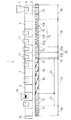
図1〜図4は本発明に係る同方向回転噛み合い型の2軸押出機1を示したものである。本押出機は、左右一対の混練スクリュー体2,2と、これらの混練スクリュー体2,2を回転自在に支持するバレル体3とを有している。バレル体3は複数のバレルセグメント4を軸心方向に接続して構成されている。
なお、説明において、図1の右側を上流側又は前側と呼び、図1の左側を下流側又は後側と呼ぶ。
Hereinafter, embodiments of an extruder according to the present invention will be described.
1 to 4 show a twin-screw extruder 1 of the same direction rotating mesh type according to the present invention. The present extruder has a pair of left and right kneading
In the description, the right side in FIG. 1 is referred to as the upstream side or the front side, and the left side in FIG. 1 is referred to as the downstream side or the rear side.
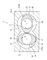
バレル体3の内部には、その上流側から下流側に向かって当該バレル体3を軸心方向に貫通する左右一対の混練室5,5が形成されている。各混練室5は、図2に示すように横断面がほぼ円形に形成されており、それらの側部同士をバレル体3中央部において互いに連通させることによって、めがね孔状にくり抜かれている。
バレル体3の上流側には材料供給口6が形成されており、この供給口6に接続したホッパー7を介して材料(被混練材)8を混練室5に供給する。ホッパー7の下流側にあるバレル体3には、投入された材料8を溶融するための電気ヒーターや加熱した油を用いた加熱装置(図示せず)が設けられており、高温となったバレル体3内を材料8が搬送されつつ融解するようになっている。
Inside the
A
バレル体3の下流側には、混練室5の内部を真空引きによって減圧状態とし、材料8からの揮発成分や水分(以下、揮発分)を取り去る、すなわち脱揮するための真空吸引用の開口10が設けられている。さらに、最下流部位には、材料8を排出するための排出部材35が設けられている。本願発明の排出部材は、バレル体内の混練物(混練が終了した材料8)が混練室5から外部に排出されて以降の位置(排出されてほどない位置)に設けられた部材であって、ダイス、オリフィス、移送配管、濾過装置が考えられる。これらはいずれも、混練物が流れるにあたっては流路抵抗が大きいものであって、後述する第2抵抗部35として作用するものである。
On the downstream side of the
バレル体3に中途部には、様々な用途に対応するためのプラグ11が設けられており、真空脱揮しない箇所ではこれを取り外して、混練室5の内部を大気に開放することによって脱揮を促進するオープンベントとして用いることも可能である。プラグ11を取り外して混練室5内に添加物などを供給するための供給手段を連結するようにしてもよい。
バレル体3の混練室5には、混練スクリュー体2がそれぞれ噛み合って回転するように挿通されており、この混練スクリュー体2が同方向に回転することで材料8を混練しつつ上流側から下流側へ送るようになっている。
The
The kneading
混練スクリュー体2は、複数のセグメントが軸芯方向に繋がるように配置されてなる。前記セグメントとしては、材料8を下流側へ搬送して押し出すための2条翼タイプのスクリューセグメント13や、材料8を練り混ぜて混合及び分散する2条翼タイプのロータセグメント14と、材料8を主に混合する2条翼タイプのニーディングセグメント15(ニーディングディスクセグメント)とがある。
図1に示すように、混練スクリュー体2は、上流側から第1送り部18、第1混練部19、第2送り部23、第1抵抗部24、脱揮部25、第2充満部28、第2抵抗部35となっており、第1抵抗部24、第2抵抗部35は、脱揮部25の上流側及び下流側に材料8を充満させるために、材料8の下流側への流れに対して抵抗となる抵抗体である。この抵抗体によって材料の流れが妨げられることで材料8の充満部が形成され、該充満部で脱揮部25の気密性が保たれるようになる。
The kneading
As shown in FIG. 1, the kneading
詳しくは、混練スクリュー体2の最上流側は、スクリューセグメント13を軸芯方向に連結して構成された第1送り部18となっている。スクリューセグメント13は回転中心Oを挟んで径方向で互いに反対向きに突出する一対のフライトを有し、これらのフライトは混練室5の内面30に対するチップクリアランス(隙間)が極めて小さい状態で軸心方向に螺旋状に捩じれている。
第1送り部18は、スリューセグメントのフライト間で形成された溝部29で、材料8を下流側に搬送する機能を有しているが、同材料8を混練する機能はほとんど無い。
Specifically, the uppermost stream side of the kneading
The
第1送り部18に隣接する下流側は第1混練部19となっており、ニーディングセグメント15とロータセグメント14が組み合わさって構成されている。
ニーディングセグメント15は、平板状の複数枚のニーディングディスクを互いに接合することによって構成されている。ニーディングディスクのフライトは、前記スクリューセグメント13と同じ断面を有すると共にチップクリアランス(フライト先端部と混練室内壁30との隙間)の極めて小さい2条翼タイプで、軸芯と平行に延びるように形成されている。このため、当該ニーディングセグメント15を通過する材料8は、チップクリアランスを通過する際に高い剪断力を受けて混練されることになる。
A downstream side adjacent to the
The kneading
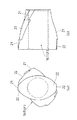
一方、ロータセグメント14として、送りセグメント14F及び戻しセグメント14Bが採用されている。送りセグメント14Fは、図3に示すように、材料8を下流側に搬送するようにフライト20が軸心方向に対して螺旋状に捩じれている。
戻しセグメント14Bは、前記送りセグメント14Fのフライト20をちょうど逆向きに捩じった形状に形成されており、材料8を上流側に戻しながら混練することで混練室5内の材料8の充満率を増大させて混練度合いを高めるように働く。
図3に示すように、ロータセグメント14のフライト20は、チップクリアランスが小さい高位チップ部21と、チップクリアランスが大きい低位チップ部22とを軸心方向に交互に並設することによって構成されている。混練スクリューが回転したときに、高位チップ部21のチップクリアランスを材料8が通過することで、材料8に対して大きな剪断力を付与し、混練室5の内面30に付着した材料8の表層を掻き落とす機能を有する。
On the other hand, as the
The
As shown in FIG. 3, the
低位チップ部22は、高位チップ部21に比べて大きなチップクリアランスが出現するように径方向の突出度合いが小さくなっている。このため、混練スクリュー体2が回転したとき、チップクリアランスにおける材料8により小さな剪断力を加えて材料8の通過量を増加させ、混練室5内における材料8の流動を促進して材料の混合度合いを高める。
送りセグメント14Fのフライト20の捩じれ角度は軸心方向に対して約30度に設定され、かつ、戻しセグメント14Bのフライト20の捩じれ角度はその逆の約−30度に設定されている。
The low-
The twist angle of the
第1混練部19を構成するロータセグメント14は、図1に示すように隣り合うセグメントに対して不連続に接合されてあってもよいが、段差ができないように連続的に接合してもよい。なお、第1混練部19に中立セグメント14Nを設けるようにしてもよい。
前記第1混練部19の下流側は、第2送り部23となっている。
第2送り部23は、第1送り部18と略同様にスクリューセグメント13から構成されており、上流側部分23Aは、第1スクリューセグメント13と略同様な作用を奏する。
この第2送り部23は更に下流側部分23Bを有しており、その下流側部分23Bには隣接して、第1抵抗部24が設けられている。
The
A downstream side of the
The
The
第1抵抗部24は、材料8を上流側に移送可能とする1つのスクリューセグメントであって、そのフライト20は、材料8を上流側に移送可能な逆ネジ状態で捩れている。そのため、第1抵抗部24は材料8の流れに対する抵抗体として働く。つまり、上流側から移送されてきた材料8は、第1抵抗部24が流れに対する抵抗となって、その上流側のスクリューセグメント23Bに材料8が滞留するようになる。そして、その部分が材料8の充満部(第1充満部23B)となる。その結果、当該第1充満部23Bをもって上流側空間と下流側空間とを確実に遮断でき、後述する脱揮部25が上流側と連通することを防止することができる。
The
前記第1抵抗部24の隣接下流側は脱揮部25となっている。
脱揮部25は、材料8中に存在する揮発分を蒸発させ外部に放出する役目を有し、この脱揮作用により材料8の成分調整がなされる。本実施形態の脱揮部25は、上流側の脱揮セグメント部26とその下流側に位置する第3送り部27とからなっている。
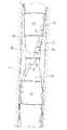
脱揮セグメント部26は、径方向で互いに反対向きに突出する一対のフライト20を備えた2条翼ロータセグメント16群から構成されている。この2条翼ロータセグメント16は、第1混練部19に用いられていた送りセグメント14Fと略同一形状を有するものであって、材料8を練り混ぜる機能を有しており、図4に示すように、軸芯方向で隣り合うセグメント間で段差ができないように連設されている。ゆえに、軸芯方向で隣り合うフライト20及びフライト20間に形成された溝部29は連続するようになり、脱揮セグメント部26は全体が滑らかなネジ状となっている。
A
The
The
この脱揮セグメント部26は、材料8を上流側に押し戻すフライトを有しておらず、材料8を下流側に送りながら練り混ぜるフライトを備えたセグメント16から構成されている。そのため、練り混ぜに伴った材料の表面更新による揮発分の分離が促進される一方で、材料が押し戻されて充満することがないため、脱揮セグメント部26に対応する混練室5の広い(長い)範囲を後述する真空ベント10による負圧領域として利用することができる。
前記フライト20の先端には、材料8の薄膜形成とその掻き取りをすることで材料8の脱揮をさらに促進するべく、材料8の薄膜形成が可能なように混練室5とのチップクリアランスが広く設定された低位チップ部22と、前記薄膜の掻き取りが可能なように混練室5とのチップクリアランスが狭く設定されている高位チップ部21とが形成されている。図3に示すように、一方のフライト20の前後両側が高位チップ部21で且つ中央部が低位チップ部22となっている場合、他方のフライト20は、その前後両側が低位チップ部22で且つ中央部が高位チップ部21となっている。こうすることで、脱揮セグメント部26は軸芯方向及び周方向で変化するチップ部を備えることになる。
高位チップ部21と低位チップ部22との形状は第1混練部19の送りセグメント14Fと略同一である。
The
The tip of the
The shapes of the high-
混練スクリュー体2が回転すると、2条翼ロータセグメント16のフライト20は、周方向および軸方向に交互に、狭いチップクリアランス→広いチップクリアランス→狭いチップクリアランスと変化する。
2条翼ロータセグメント16のフライト20の捩れ角は、混練スクリュー体2の軸芯方向に対して0°より大きく60°以下の範囲となっている。なお、捩れ角とは、軸方向に対するフライト20頂部の傾き角であって、2条翼ロータセグメント16の展開図において、フライト20頂部が軸方向から傾斜した角度である。これにより、脱揮セグメント部26の螺旋形状はその軸芯に対して緩やかなものとなると同時に溝部29も緩やかな螺旋で、溝部29により形成される流路の全長がスクリューセグメント13に比して短くなり、ひいては後述する真空吸引用の開口10までの流動抵抗が小さいものとなっている。
When the kneading
The twist angle of the
なお、前記捩れ角が0°に近づくと材料8の送り作用は小さくなるものの、材料8に対するして加えることのできる剪断力は大きくなる。ゆえに、上記フライト20の捩れ角を15°以上45°以下とすると材料8に対する剪断力が好適なものとなり非常に好ましい。
前記脱揮セグメント部26の隣接下流側には、脱揮部25を構成する第3送り部27が設けられている。この第3送り部27は、第1送り部18と略同一の構成を有しており、材料8を下流側に送る機能を有している。
When the twist angle approaches 0 °, the feeding action of the
On the downstream side adjacent to the
本実施形態の場合は、この第3送り部27の最上流側であって脱揮セグメント部26の最下流近傍(下流側)に対応するバレルセグメント4に、真空吸引用の開口すなわち真空ベント10が設けられている。
この真空ベント10を介して前記脱揮部25を減圧することで、材料8からの脱揮が行われる。前記脱揮セグメント部26のフライト20の側面とバレル内面30とで形成される空間である溝部29は、真空ベント10に通じるようになっており、材料8から蒸発した脱揮分は、この溝部29を流路として通じて真空ベント10に流れ込み、外部に排出されるようになる。前述の如く、当該溝部29はその流路長さが短い上に滑らかな流路を形成しているため、同じL/D(Lは脱揮セグメント部26の長さ、Dは混練室5の直径)のスクリューセグメントに比べて揮発分の流れに対する流動抵抗が少なく、真空ベント10からの減圧による脱揮効果が脱揮セグメント部26全域に及ぶようになっている。
In the case of the present embodiment, an opening for vacuum suction, that is, a
Volatilization from the
前記第3送り部27の隣接下流側は、第2充満部28となっている。
第2充満部28は、下流側へゆくにしたがってフライトピッチが密になるように配置されたスクリューセグメント13群からなっており、詳しくは、図1に示すように、上流側からフライトの配置ピッチが異なる4つのスクリューセグメント13が連なるように配設されており、もっとも上流側のセグメントは前記第3送り部27を構成するスクリューセグメント13と略同一フライトピッチであり、後3つのセグメントは順にピッチ間隔が短いものとなっている。
A downstream side adjacent to the
The
また、同軸に連なるバレル体3群の最下流側には、排出部材であって抵抗体として作用するダイス35が取り付けられており、その流動抵抗に抗して混練物は押し出されるため、第2充満部28で混練物が密になり材料8の充満部となる。この第2充満部28は、隣接する脱揮部25と、脱揮部25よりも下流側の領域とを確実に隔離するようになる。
以上のように、材料8の混練機能を有すると共に材料8が充満せず下流側へ移送可能に捩れたフライトを有するセグメントから構成された脱揮セグメント部26を設けることで、材料8の表面更新工程を積極的に揮発分の分離促進工程に利用し、同時に脱揮セグメント部26に対応する混練室5を長い範囲(全域)に亘って真空吸引するための負圧領域として利用することができる。
Further, a die 35 that is a discharge member and acts as a resistor is attached to the most downstream side of the group of
As described above, the surface of the
また、脱揮部25の上流側に第1抵抗部24(抵抗体)を設けると共に、下流側に第2抵抗部35(抵抗体)を設けて、それぞれの上流側で隣接する第1充満部23Bと第2充満部28とに材料8の充満領域が形成されることで、脱揮部25の気密性が保たれるようになり、脱揮部25の負圧状態が確実に維持されるようになる。ゆえに、材料8からの水分など蒸発を促進することができると共に、揮発した成分は真空ベント10を介して効果的に外部に排出されるようになる。
なお、脱揮セグメント部26の混練フライト20には、混練室内壁30への材料8の薄膜形成とその掻き取りを行うように低位チップ部22と高位チップ部21とが設けられている。このため、通常の混練フライトを用いる場合よりも更に表面更新作用が発揮される。
Moreover, while providing the 1st resistance part 24 (resistor) in the upstream of the
The kneading
脱揮セグメント部26と第3送り部27とで構成されている脱揮部25の長さは、本実施形態の場合、L/D=16(Lは脱揮部25の長さ、Dは混練室5の直径)と比較的長いものとなっている。
次に、本実施形態の2軸連続押出機1の作動態様について説明する。
2軸押出機1によってプラスチックコンパウンド等の複合樹脂材料を製造するには、まず、合成樹脂製のペレット等よりなる材料8をバレル体3の上流側ホッパー7に供給し、その材料8を第1送り部18で下流側に移送しながら加熱装置9で加熱し、さらに、第1混練部19で混練して溶融させる。
In the case of this embodiment, the length of the
Next, the operation | movement aspect of the biaxial continuous extruder 1 of this embodiment is demonstrated.
In order to manufacture a composite resin material such as a plastic compound by the twin-screw extruder 1, first, a
第1混練部19のロータセグメント14で混練が行われる際、低位チップ部22の大きいチップクリアランスを材料8が通過することで、添加物の練り込みが促進され、その一方で、低位チップ部22により混練室5内壁30へ材料8が付着しても、高位チップ部21によってその材料8が混練室5の内面30から掻き取られるようになる。このため、添加物の練り込み効果を向上させつつ、材料8が層状に付着することによる有効径の縮小が防止される。
第1混練部19で混練が終わった材料8は、第2送り部23で下流側に移送され脱揮部25へと導入される。脱揮部25では、真空ベント10によって混練室5内は減圧状態となっており材料8は、脱揮セグメント部26で練り混ぜられて表面が更新されながら強制的に脱揮される(脱気・脱水される)。
When kneading is performed in the
The
加えて、脱揮セグメント部26の低位チップ部22のチップクリアランスを材料8が通過する際には、混練室内面30に材料8が薄膜状に塗布され、その一方で、高位チップ部21によって当該薄膜が内面30から掻き取られることにより、材料8のより高レベルでの表面の更新が絶えず行われ、薄膜表面からの揮発成分や水分の蒸発が促進されることになる。
また、高位チップ部21を材料8が通過する際には、材料8に高いせん断の加えられることになるため、内部に含まれている充填剤あるいは添加剤などの凝集体、又はポリマーゲルなどを効果的に拡散させ複合樹脂材料内に混合させることができるようになる。すなわち、当該脱揮セグメント部26では、混練物の脱揮・乾燥と同時に充填剤、ポリマーゲルなどの分散・混合を図ることができる。
In addition, when the
In addition, when the
一方、脱揮セグメント部26の溝部29は、蒸発した揮発成分が真空ベント10に流れ込むための流路として働き、この流路の真空ベント10までの距離は、脱揮セグメント部26を同じL/Dのスクリューセグメント13で構成した場合と比較して非常に短いものとなっているため、真空状態の領域が脱揮ロータ26の広範囲に亘って形成されると共に、流路抵抗が少なくなり揮発成分を真空ベント10まで容易に流出させることができるようになっている。
真空ベント10からの吸引による減圧状態は、第3送り部27に移送された材料8に対しても及び、その部分でも脱揮が行われるようになる。
On the other hand, the
The depressurized state due to suction from the
なお、脱揮部25の上流側の第1充満部23Bでは、材料8が第1抵抗部24の逆ネジにより滞留状態となっており、下流側の第2充満部28には、ダイス35の流路抵抗により材料8が滞留しているため、脱揮部25の前後両側は常に密閉状態であって、脱揮部25の減圧状態は確実に保たれるようになっている。
脱揮が終わった材料8は、ダイス35から押し出される。
図5は、本発明の第2実施形態に係る2軸連続押出機を示している。
本実施形態の押出機1が第1実施形態と異なる点は、複数の脱揮部31,32,34と中間抵抗部33,33(抵抗体)を有することである。
In addition, in the
The
FIG. 5 shows a twin-screw continuous extruder according to the second embodiment of the present invention.
The difference of the extruder 1 of this embodiment from the first embodiment is that it has a plurality of
すなわち、第1脱揮部31の下流側に逆ネジ状のスクリューセグメント13からなる中間抵抗部33を設け、その隣接する下流側に第2脱揮部32を設けている。第2脱揮部32の隣接下流側には、さらに中間抵抗部33が設けられ、その隣接下流側には、第3脱揮部34が設けられている。第3脱揮部34の下流にはフライトピッチが密なるように接続されたスクリューセグメント13群からなる第2充満部28が設けられている。
各脱揮部31,32,34は、第1実施形態の第1脱揮部31と略同様の構成を有しており、それぞれに設けられた真空ベント10を介して材料8からの脱揮を行うものとなっている。各抵抗部24,33,33も第1実施形態の抵抗部24,35と略同様の働きをしてその上流側に材料8を充満させ充満部としシール性を高めるようにしている。
That is, the
Each
前述の脱揮部25が複数設けられていることで、材料8の混練を順次行いつつ脱揮を確実に行うことが可能となる。
なお、本実施形態の場合、第1混練部19の長さはL/D=10(Lは混練部の長さ、Dは混練室の直径)としており、第2および第3混練部の長さはL/D=4としている。第1混練部19の長さを長くしているのは、材料8中への添加物の分散効果を高める狙いがある。脱揮を主目的とした場合には、L/D=2〜10程度でも十分な効果を得ることが可能である。
By providing a plurality of the
In the case of this embodiment, the length of the first kneading
また、各脱揮部31,32,34の上流側・下流側にそれぞれ抵抗部24,33,33,28を設けて圧力シールを施しているが、中間抵抗部33,33は必要に応じて省略することも可能である。これは、第1充満部23Bと第2充満部28とで、第1脱揮部31〜第3脱揮部34の圧力シールを行うことができるためである。
なお、本発明は前記した各実施形態に限定されるものではない。
すなわち、本発明は、3条翼や単翼タイプのセグメントを採用した押出機にも採用することができる。単軸押出機に適用してもよい。
Moreover, although
Note that the present invention is not limited to the embodiments described above.
That is, the present invention can also be applied to an extruder that employs a triple-blade or single-blade type segment. You may apply to a single screw extruder.
また、事前に混練して溶融状態にある材料8を本発明にかかる押出機1に供給する場合には、第1混練部19を設ける必要はない。
また、各抵抗部24,33は逆ネジのスクリューセグメント13から構成されているが、これに限定されず材料8の下流側への流れに対する抵抗となり、且つ材料8を滞留させて充満部を作るものであればよく、逆ネジのロータセグメント14で構成されていてもよい。第2抵抗部35はダイスで構成されているが、オリフィス、移送配管、濾過装置など材料8の下流側への流れに対する抵抗となるものであれば何ら問題はない。
Further, when the
Further, each of the
また、2条翼ロータセグメント16のフライト20の捩れ角は、混練スクリュー体2の軸芯方向に対して0°より大きいものとしていたが、一部又は最終部のフライト捩れ角が0°であっても何ら問題はない。
In addition, the twist angle of the
[実施例1]
第1実施形態で述べた2軸押出機1を用いて、材料8を実際に混練した例を以下述べる。
材料8はポリスチレン樹脂であって、その中に含まれるエチルベンゼンおよびスチレンモノマーを脱揮部25で脱揮するようにしている。まず、第1混練部19にてポリスチレンを可塑化・溶融し、脱揮部25ではポリスチレンを前方に向かって送りながら揮発成分であるエチルベンゼン、スチレンモノマーを蒸発させ、真空ポンプを用いて真空ベント10から吸引することで外部に排出するようにした。
[Example 1]
An example in which the
The
混練スクリュー体2の全長はL/D=50、脱揮部25の長さはL/D=16であり、スクリューの直径は46mmである。スクリュー回転数を400rpm、材料8の押出量を100kg/h、真空ベント10部の圧力を0.5kPaの条件にて、ポリスチレンの脱揮を行った。
当該押出機1から排出されたポリスチレンをストランドカット方式にて造粒し、エチルベンゼンおよびスチレンモノマーの含有率を測定したところ、エチルベンゼン含有率は0.054%、スチレンモノマー含有率は、0.0012%となっていた。原料ポリスチレン中に含まれるエチルベンゼンおよびスチレンモノマーの含有率は、0.98%および0.042%であり、効果的な脱揮が行われたことが判明した。
[実施例2]
材料8はポリスチレン樹脂であって、カーボンブラックを混合したコンパウンドを製造した例を示す。押出機1としては第2実施形態で説明したものを用い、混練スクリュー体2の直径は46mm、全長はL/D=54である。
The total length of the kneading
The polystyrene discharged from the extruder 1 was granulated by a strand cut method, and the ethylbenzene and styrene monomer contents were measured. The ethylbenzene content was 0.054% and the styrene monomer content was 0.0012%. It was. The contents of ethylbenzene and styrene monomer contained in the raw polystyrene were 0.98% and 0.042%, and it was found that effective devolatilization was performed.
[Example 2]
第1混練部19は、ロータセグメント14およびニーディングセグメント15(3枚のニーディングディスクを各々45°づつ位相をずらしたもの)で構成され、ポリスチレンへのカーボンブラックの練り込みおよび分散・混合を行うようにしている。
材料押し出し量150kg/h、スクリュー回転数400rpm、混練物の温度228℃の条件下での混練作業の結果として、スチレンモノマー含有率0.001%以下の揮発性物質の含有率が少なく且つカーボン分散度の優れたコンパウンドが製造できた。
The
As a result of the kneading operation under the conditions of material extrusion rate 150 kg / h, screw rotation speed 400 rpm, kneaded material temperature 228 ° C., the content of volatile substances with a styrene monomer content of 0.001% or less is low and carbon dispersion The compound with excellent degree could be manufactured.
1 押出機
2 混練スクリュー体
3 バレル体
5 混練室
8 材料
10 真空吸引用の開口(真空ベント)
13 スクリューセグメント
16 2条翼ロータセグメント
20 (ロータセグメントの)フライト
21 高位チップ部
22 低位チップ部
23B 第1充満部
24 第1抵抗部
25 脱揮部
28 第2充満部
35 第2抵抗部(排出部材)
DESCRIPTION OF SYMBOLS 1
13
Claims (7)
前記混練スクリュー体(2)には、材料(8)を下流側に移送可能なように捩れた混練フライト(20)を有すると共にこの混練フライト(20)で材料(8)を下流側に送りつつ練り混ぜて揮発分を分離する脱揮セグメント部(26)が備えられ、
前記バレル体(3)には、当該脱揮セグメント部(26)が挿通している混練室(5)に通じる真空吸引用の開口(10)が設けられ、
前記脱揮セグメント部(26)の上流側及び前記開口(10)の下流側のそれぞれに、材料(8)が混練室(5)内に充満する充満部(23B)(28)が設けられており、
前記脱揮セグメント部(26)は、径方向で互いに反対向きに突出する一対の混練フライト(20)(20)を備えた2条翼ロータセグメント(16)からなり、
前記混練室内壁(30)への材料(8)の薄膜形成とその掻き取りをすることで材料(8)からの揮発分の分離を促進させるべく、前記混練フライト(20)の先端部には、材料(8)の薄膜形成が可能となるように混練室内壁(30)とのチップクリアランスが大きく設定された低位チップ部(22)と、前記薄膜を掻き取り可能なように混練室内壁(30)とのチップクリアランスが小さく設定されている高位チップ部(21)とが形成されていることを特徴とする押出機。 It comprises a barrel body (3) having a kneading chamber (5) therein and a plurality of segments (13) (14) (15) (16), and is rotatably inserted into the kneading chamber (5) and rotates. In an extruder having a kneading screw body (2) that is fed from the upstream side to the downstream side while kneading the material (8),
The kneading screw body (2) has a kneading flight (20) twisted so that the material (8) can be transferred to the downstream side, and the material (8) is sent to the downstream side by the kneading flight (20). A devolatilizing segment (26) for kneading and separating volatile components is provided,
The barrel body (3) is provided with a vacuum suction opening (10) leading to a kneading chamber (5) through which the devolatilization segment portion (26) is inserted,
Filling portions (23B) (28) in which the material (8) is filled in the kneading chamber (5) are provided on the upstream side of the devolatilization segment portion (26) and on the downstream side of the opening (10), respectively. And
The devolatilization segment portion (26) is composed of a two-blade rotor segment (16) provided with a pair of kneading flights (20) (20) protruding in opposite directions in the radial direction,
In order to promote separation of volatile matter from the material (8) by forming a thin film of the material (8) on the kneading chamber wall (30) and scraping the material (8), The lower tip portion (22) having a large tip clearance with the kneading chamber inner wall (30) so that a thin film of the material (8) can be formed, and the kneading chamber wall (so that the thin film can be scraped off) 30) A high-order tip portion (21) having a small tip clearance with respect to 30) is formed .
Priority Applications (4)
| Application Number | Priority Date | Filing Date | Title |
|---|---|---|---|
| JP2004182905A JP4252016B2 (en) | 2004-06-21 | 2004-06-21 | Extruder |
| US11/149,198 US7419295B2 (en) | 2004-06-21 | 2005-06-10 | Extruder |
| DE102005028401.9A DE102005028401B4 (en) | 2004-06-21 | 2005-06-20 | extruder |
| CN200510078659XA CN1721157B (en) | 2004-06-21 | 2005-06-21 | extruder |
Applications Claiming Priority (1)
| Application Number | Priority Date | Filing Date | Title |
|---|---|---|---|
| JP2004182905A JP4252016B2 (en) | 2004-06-21 | 2004-06-21 | Extruder |
Publications (2)
| Publication Number | Publication Date |
|---|---|
| JP2006001252A JP2006001252A (en) | 2006-01-05 |
| JP4252016B2 true JP4252016B2 (en) | 2009-04-08 |
Family
ID=35514238
Family Applications (1)
| Application Number | Title | Priority Date | Filing Date |
|---|---|---|---|
| JP2004182905A Expired - Lifetime JP4252016B2 (en) | 2004-06-21 | 2004-06-21 | Extruder |
Country Status (4)
| Country | Link |
|---|---|
| US (1) | US7419295B2 (en) |
| JP (1) | JP4252016B2 (en) |
| CN (1) | CN1721157B (en) |
| DE (1) | DE102005028401B4 (en) |
Families Citing this family (38)
| Publication number | Priority date | Publication date | Assignee | Title |
|---|---|---|---|---|
| JP3868757B2 (en) * | 2001-04-25 | 2007-01-17 | 株式会社神戸製鋼所 | Rubber composition kneading apparatus and kneading method |
| JP4252016B2 (en) * | 2004-06-21 | 2009-04-08 | 株式会社神戸製鋼所 | Extruder |
| WO2007006327A1 (en) * | 2005-07-12 | 2007-01-18 | Borealis Technology Oy | Counter-rotating twin screw extruder |
| JP4445478B2 (en) * | 2006-03-10 | 2010-04-07 | 株式会社日本製鋼所 | Plasticizing and kneading extruder for plastic raw materials |
| BRPI0712343B1 (en) | 2006-06-09 | 2014-09-02 | Kobe Steel Ltd | HIGH CLEANING STEEL SPRING |
| JP4205127B2 (en) * | 2006-11-28 | 2009-01-07 | 株式会社神戸製鋼所 | Kneading screw, twin screw extruder, and assembling method of kneading screw |
| DE502007003920D1 (en) * | 2006-12-14 | 2010-07-08 | Sulzer Chemtech Ag | Porous dosing element with coating |
| JP4907366B2 (en) * | 2007-01-26 | 2012-03-28 | 株式会社神戸製鋼所 | Extruder screw, bearing segment used therefor, and twin screw extruder provided with extruder screw |
| JP4746014B2 (en) | 2007-07-09 | 2011-08-10 | 株式会社日本製鋼所 | Melt-kneading devolatilizing extruder |
| JP5085582B2 (en) * | 2009-02-06 | 2012-11-28 | 株式会社日本製鋼所 | Twin screw extruder for devolatilization |
| ES2584514T3 (en) * | 2009-07-16 | 2016-09-28 | Blach Verwaltungs Gmbh & Co. Kg | Extruder |
| US9481759B2 (en) | 2009-08-14 | 2016-11-01 | Boral Ip Holdings Llc | Polyurethanes derived from highly reactive reactants and coal ash |
| US8846776B2 (en) | 2009-08-14 | 2014-09-30 | Boral Ip Holdings Llc | Filled polyurethane composites and methods of making same |
| US9238723B2 (en) | 2010-10-29 | 2016-01-19 | Dow Global Technologies Llc | Melt devolatilization extrusion process |
| JP5675956B2 (en) * | 2011-03-08 | 2015-02-25 | 日立マクセル株式会社 | Kneading apparatus and method for producing thermoplastic resin molded body |
| JP5684063B2 (en) * | 2011-07-28 | 2015-03-11 | 株式会社日本製鋼所 | Volatilization apparatus and method in an extruder |
| CN103890048B (en) | 2011-09-27 | 2015-12-02 | 陶氏环球技术有限责任公司 | Melt Devolatilization Extrusion Method |
| SA112330882B1 (en) * | 2011-09-28 | 2018-01-24 | ارلانكسيو دوتشلاند جى ام بى اتش. | Apparatus for removing volatiles from polymer-containing media |
| CA2851349C (en) | 2011-10-07 | 2020-01-21 | Russell L. Hill | Inorganic polymer/organic polymer composites and methods of making same |
| JP6179318B2 (en) * | 2012-09-26 | 2017-08-16 | 三菱ケミカル株式会社 | Method for producing polycarbonate resin |
| JP5761871B2 (en) * | 2013-08-23 | 2015-08-12 | 株式会社日本製鋼所 | Twin screw extruder used for manufacturing fiber reinforced resin composition and method for manufacturing fiber reinforced resin composition |
| JP5619239B1 (en) * | 2013-08-27 | 2014-11-05 | 株式会社日本製鋼所 | Bent type twin-screw kneading extrusion apparatus and method |
| JP6341921B2 (en) * | 2013-09-26 | 2018-06-13 | 伏虎金属工業株式会社 | Blender pump |
| JP6242232B2 (en) | 2014-02-13 | 2017-12-06 | 株式会社神戸製鋼所 | Continuous kneader |
| JP6251089B2 (en) * | 2014-03-13 | 2017-12-20 | マクセルホールディングス株式会社 | Manufacturing method of molded body |
| JP6198666B2 (en) * | 2014-04-22 | 2017-09-20 | 宏平 澤 | Kneading equipment |
| WO2016018226A1 (en) | 2014-07-28 | 2016-02-04 | Crocco Guy | The use of evaporative coolants to manufacture filled polyurethane composites |
| US9752015B2 (en) | 2014-08-05 | 2017-09-05 | Boral Ip Holdings (Australia) Pty Limited | Filled polymeric composites including short length fibers |
| WO2016118141A1 (en) | 2015-01-22 | 2016-07-28 | Boral Ip Holdings (Australia) Pty Limited | Highly filled polyurethane composites |
| WO2016195717A1 (en) | 2015-06-05 | 2016-12-08 | Boral Ip Holdings (Australia) Pty Limited | Filled polyurethane composites with lightweight fillers |
| JP6798101B2 (en) | 2015-10-19 | 2020-12-09 | 住友ゴム工業株式会社 | Extruder |
| WO2017082914A1 (en) | 2015-11-12 | 2017-05-18 | Boral Ip Holdings (Australia) Pty Limited | Filled polyurethane composites with size-graded fillers |
| US11273588B1 (en) * | 2017-10-13 | 2022-03-15 | Certainteed Llc | Extruder including rotating outlet and method of using the same |
| JP7172405B2 (en) * | 2018-10-09 | 2022-11-16 | 東レ株式会社 | Method for producing thermoplastic resin composition |
| EP4073126A4 (en) * | 2019-12-12 | 2023-12-20 | Archer Daniels Midland Company | ULTRA-FINE FLOUR COMPOSITION BASED ON STARCH OR GRAIN AND ASSOCIATED METHODS |
| CN114272878B (en) * | 2021-12-29 | 2024-02-13 | 万华化学集团股份有限公司 | A two-in-one devolatilization and feeding device, solution polymerization device, and polymerization method |
| CN115317936B (en) * | 2022-06-30 | 2024-09-20 | 武汉纺织大学 | Thin film evaporator and method for removing monomer and oligomer in PA6 polymeric melt |
| CN117644594A (en) * | 2023-11-30 | 2024-03-05 | 张家港市美特高分子材料有限公司 | Extrusion granulating method for thermoplastic plastics |
Family Cites Families (14)
| Publication number | Priority date | Publication date | Assignee | Title |
|---|---|---|---|---|
| US3917507A (en) * | 1971-02-22 | 1975-11-04 | Welding Engineers | Countercurrent combined liquid and vapor stripping in screw devolatilizer |
| US3985348A (en) * | 1975-01-14 | 1976-10-12 | W Bar E, Incorporated | Apparatus and method for feeding a powdery material to a plasticized, pressurized polymer |
| JPS5249267A (en) * | 1975-10-17 | 1977-04-20 | Japan Steel Works Ltd | Degassing modifying extruder |
| US4491417A (en) * | 1983-04-29 | 1985-01-01 | Usm Corporation | Devolatilizing mixing extruder |
| DE3744193C1 (en) * | 1987-12-24 | 1989-01-26 | Berstorff Gmbh Masch Hermann | Process and extruder for degassing thermoplastic plastic melts over a wide range of viscosities |
| CN2048820U (en) | 1989-07-01 | 1989-12-06 | 北京化工学院 | Two-stage vented extruder screw |
| DE4021751A1 (en) * | 1990-07-07 | 1992-01-16 | Berstorff Gmbh Masch Hermann | DEGASSING EXTRUDERS |
| JP2909577B2 (en) * | 1993-10-29 | 1999-06-23 | トヨタ自動車株式会社 | Resin waste material recycling method and apparatus |
| IT1283652B1 (en) * | 1996-08-02 | 1998-04-23 | Pomini Spa | PROCEDURE FOR THE CONTINUOUS MIXING AND EXTRUSION OF POLYMERIC MATERIALS WITH DRY PRE-MIXING OF THE MATERIAL AND |
| JP3656957B2 (en) | 2001-01-16 | 2005-06-08 | 株式会社神戸製鋼所 | Biaxial continuous kneader and kneading method using the same |
| JP3868757B2 (en) * | 2001-04-25 | 2007-01-17 | 株式会社神戸製鋼所 | Rubber composition kneading apparatus and kneading method |
| US6833096B2 (en) | 2001-08-29 | 2004-12-21 | General Electric Company | Method for removing water and other volatile components from polymer powders |
| KR100541042B1 (en) * | 2002-09-04 | 2006-01-10 | 제일모직주식회사 | Extruder plant for producing flame retardant resin composition pellets |
| JP4252016B2 (en) * | 2004-06-21 | 2009-04-08 | 株式会社神戸製鋼所 | Extruder |
-
2004
- 2004-06-21 JP JP2004182905A patent/JP4252016B2/en not_active Expired - Lifetime
-
2005
- 2005-06-10 US US11/149,198 patent/US7419295B2/en active Active
- 2005-06-20 DE DE102005028401.9A patent/DE102005028401B4/en not_active Expired - Lifetime
- 2005-06-21 CN CN200510078659XA patent/CN1721157B/en not_active Expired - Lifetime
Also Published As
| Publication number | Publication date |
|---|---|
| DE102005028401B4 (en) | 2016-11-10 |
| US7419295B2 (en) | 2008-09-02 |
| US20060003042A1 (en) | 2006-01-05 |
| DE102005028401A1 (en) | 2006-02-02 |
| CN1721157A (en) | 2006-01-18 |
| CN1721157B (en) | 2010-06-16 |
| JP2006001252A (en) | 2006-01-05 |
Similar Documents
| Publication | Publication Date | Title |
|---|---|---|
| JP4252016B2 (en) | Extruder | |
| US6682213B2 (en) | Twin-screw continuous kneading apparatus and kneading method using the same | |
| CN112203818B (en) | Kneading method and kneaded product | |
| EP1156918B1 (en) | Screw extruder with improved dispersive mixing elements | |
| CN101037020B (en) | Kneading extruder | |
| EP1711322B1 (en) | Apparatus for plasticating thermoplastics | |
| US8899820B2 (en) | Melting kneading devolatilizing extruder | |
| CN109789625A (en) | Degassing when the material of preferably plastics squeezes out | |
| US3085288A (en) | Material treating apparatus | |
| JP2010105285A5 (en) | ||
| JP2009196303A (en) | Kneading disk segment and twin-screw extruder | |
| JP2001129823A (en) | Twin-spindle continuous kneader | |
| CN104309095A (en) | Double-screw extruder | |
| JP3963042B2 (en) | Continuous kneader and rotor of continuous kneader | |
| US5356208A (en) | Screw element having shearing and scraping flights | |
| JP3812964B2 (en) | Twin screw extruder | |
| US20030206482A1 (en) | Extrusion screw tip | |
| JP3530334B2 (en) | Continuous kneader and rotor of continuous kneader | |
| US20200055227A1 (en) | Vent Type Extruder and Method of Manufacturing Cable Jacket Using the Same | |
| CN102275285A (en) | Differential conical three-screw extruder with screws arranged triangularly | |
| JP3204869B2 (en) | Twin screw extruder | |
| CN101983121A (en) | Extruder and process for extruding a polymer | |
| JP2018504301A (en) | Stuffing screw | |
| WO2004089587A1 (en) | Screw-type kneading/extruding machine | |
| JPH021650B2 (en) |
Legal Events
| Date | Code | Title | Description |
|---|---|---|---|
| A621 | Written request for application examination |
Free format text: JAPANESE INTERMEDIATE CODE: A621 Effective date: 20060925 |
|
| A977 | Report on retrieval |
Free format text: JAPANESE INTERMEDIATE CODE: A971007 Effective date: 20081030 |
|
| A131 | Notification of reasons for refusal |
Free format text: JAPANESE INTERMEDIATE CODE: A131 Effective date: 20081111 |
|
| A521 | Request for written amendment filed |
Free format text: JAPANESE INTERMEDIATE CODE: A523 Effective date: 20081218 |
|
| TRDD | Decision of grant or rejection written | ||
| A01 | Written decision to grant a patent or to grant a registration (utility model) |
Free format text: JAPANESE INTERMEDIATE CODE: A01 Effective date: 20090120 |
|
| A01 | Written decision to grant a patent or to grant a registration (utility model) |
Free format text: JAPANESE INTERMEDIATE CODE: A01 |
|
| A61 | First payment of annual fees (during grant procedure) |
Free format text: JAPANESE INTERMEDIATE CODE: A61 Effective date: 20090120 |
|
| R150 | Certificate of patent or registration of utility model |
Ref document number: 4252016 Country of ref document: JP Free format text: JAPANESE INTERMEDIATE CODE: R150 Free format text: JAPANESE INTERMEDIATE CODE: R150 |
|
| FPAY | Renewal fee payment (event date is renewal date of database) |
Free format text: PAYMENT UNTIL: 20120130 Year of fee payment: 3 |
|
| FPAY | Renewal fee payment (event date is renewal date of database) |
Free format text: PAYMENT UNTIL: 20130130 Year of fee payment: 4 |
|
| FPAY | Renewal fee payment (event date is renewal date of database) |
Free format text: PAYMENT UNTIL: 20130130 Year of fee payment: 4 |
|
| EXPY | Cancellation because of completion of term |