EP3884343B1 - Rückprojektionssimulator mit freiformfaltspiegel - Google Patents
Rückprojektionssimulator mit freiformfaltspiegel Download PDFInfo
- Publication number
- EP3884343B1 EP3884343B1 EP19887247.5A EP19887247A EP3884343B1 EP 3884343 B1 EP3884343 B1 EP 3884343B1 EP 19887247 A EP19887247 A EP 19887247A EP 3884343 B1 EP3884343 B1 EP 3884343B1
- Authority
- EP
- European Patent Office
- Prior art keywords
- curved portion
- image
- projector
- fold mirror
- free
- Prior art date
- Legal status (The legal status is an assumption and is not a legal conclusion. Google has not performed a legal analysis and makes no representation as to the accuracy of the status listed.)
- Active
Links
Images


Classifications
-
- G—PHYSICS
- G03—PHOTOGRAPHY; CINEMATOGRAPHY; ANALOGOUS TECHNIQUES USING WAVES OTHER THAN OPTICAL WAVES; ELECTROGRAPHY; HOLOGRAPHY
- G03B—APPARATUS OR ARRANGEMENTS FOR TAKING PHOTOGRAPHS OR FOR PROJECTING OR VIEWING THEM; APPARATUS OR ARRANGEMENTS EMPLOYING ANALOGOUS TECHNIQUES USING WAVES OTHER THAN OPTICAL WAVES; ACCESSORIES THEREFOR
- G03B21/00—Projectors or projection-type viewers; Accessories therefor
- G03B21/54—Accessories
- G03B21/56—Projection screens
- G03B21/60—Projection screens characterised by the nature of the surface
- G03B21/602—Lenticular screens
-
- G—PHYSICS
- G02—OPTICS
- G02B—OPTICAL ELEMENTS, SYSTEMS OR APPARATUS
- G02B5/00—Optical elements other than lenses
- G02B5/08—Mirrors
- G02B5/10—Mirrors with curved faces
-
- G—PHYSICS
- G02—OPTICS
- G02B—OPTICAL ELEMENTS, SYSTEMS OR APPARATUS
- G02B27/00—Optical systems or apparatus not provided for by any of the groups G02B1/00 - G02B26/00, G02B30/00
- G02B27/18—Optical systems or apparatus not provided for by any of the groups G02B1/00 - G02B26/00, G02B30/00 for optical projection, e.g. combination of mirror and condenser and objective
-
- G—PHYSICS
- G02—OPTICS
- G02B—OPTICAL ELEMENTS, SYSTEMS OR APPARATUS
- G02B3/00—Simple or compound lenses
- G02B3/0006—Arrays
- G02B3/0012—Arrays characterised by the manufacturing method
- G02B3/0031—Replication or moulding, e.g. hot embossing, UV-casting, injection moulding
-
- G—PHYSICS
- G02—OPTICS
- G02B—OPTICAL ELEMENTS, SYSTEMS OR APPARATUS
- G02B3/00—Simple or compound lenses
- G02B3/0006—Arrays
- G02B3/0037—Arrays characterized by the distribution or form of lenses
- G02B3/0056—Arrays characterized by the distribution or form of lenses arranged along two different directions in a plane, e.g. honeycomb arrangement of lenses
-
- G—PHYSICS
- G02—OPTICS
- G02B—OPTICAL ELEMENTS, SYSTEMS OR APPARATUS
- G02B3/00—Simple or compound lenses
- G02B3/02—Simple or compound lenses with non-spherical faces
- G02B3/08—Simple or compound lenses with non-spherical faces with discontinuous faces, e.g. Fresnel lens
-
- G—PHYSICS
- G02—OPTICS
- G02B—OPTICAL ELEMENTS, SYSTEMS OR APPARATUS
- G02B5/00—Optical elements other than lenses
- G02B5/02—Diffusing elements; Afocal elements
- G02B5/0273—Diffusing elements; Afocal elements characterized by the use
- G02B5/0278—Diffusing elements; Afocal elements characterized by the use used in transmission
-
- G—PHYSICS
- G03—PHOTOGRAPHY; CINEMATOGRAPHY; ANALOGOUS TECHNIQUES USING WAVES OTHER THAN OPTICAL WAVES; ELECTROGRAPHY; HOLOGRAPHY
- G03B—APPARATUS OR ARRANGEMENTS FOR TAKING PHOTOGRAPHS OR FOR PROJECTING OR VIEWING THEM; APPARATUS OR ARRANGEMENTS EMPLOYING ANALOGOUS TECHNIQUES USING WAVES OTHER THAN OPTICAL WAVES; ACCESSORIES THEREFOR
- G03B21/00—Projectors or projection-type viewers; Accessories therefor
- G03B21/14—Details
- G03B21/145—Housing details, e.g. position adjustments thereof
-
- G—PHYSICS
- G03—PHOTOGRAPHY; CINEMATOGRAPHY; ANALOGOUS TECHNIQUES USING WAVES OTHER THAN OPTICAL WAVES; ELECTROGRAPHY; HOLOGRAPHY
- G03B—APPARATUS OR ARRANGEMENTS FOR TAKING PHOTOGRAPHS OR FOR PROJECTING OR VIEWING THEM; APPARATUS OR ARRANGEMENTS EMPLOYING ANALOGOUS TECHNIQUES USING WAVES OTHER THAN OPTICAL WAVES; ACCESSORIES THEREFOR
- G03B21/00—Projectors or projection-type viewers; Accessories therefor
- G03B21/14—Details
- G03B21/28—Reflectors in projection beam
-
- G—PHYSICS
- G03—PHOTOGRAPHY; CINEMATOGRAPHY; ANALOGOUS TECHNIQUES USING WAVES OTHER THAN OPTICAL WAVES; ELECTROGRAPHY; HOLOGRAPHY
- G03B—APPARATUS OR ARRANGEMENTS FOR TAKING PHOTOGRAPHS OR FOR PROJECTING OR VIEWING THEM; APPARATUS OR ARRANGEMENTS EMPLOYING ANALOGOUS TECHNIQUES USING WAVES OTHER THAN OPTICAL WAVES; ACCESSORIES THEREFOR
- G03B21/00—Projectors or projection-type viewers; Accessories therefor
- G03B21/54—Accessories
- G03B21/56—Projection screens
- G03B21/60—Projection screens characterised by the nature of the surface
- G03B21/606—Projection screens characterised by the nature of the surface for relief projection
-
- G—PHYSICS
- G03—PHOTOGRAPHY; CINEMATOGRAPHY; ANALOGOUS TECHNIQUES USING WAVES OTHER THAN OPTICAL WAVES; ELECTROGRAPHY; HOLOGRAPHY
- G03B—APPARATUS OR ARRANGEMENTS FOR TAKING PHOTOGRAPHS OR FOR PROJECTING OR VIEWING THEM; APPARATUS OR ARRANGEMENTS EMPLOYING ANALOGOUS TECHNIQUES USING WAVES OTHER THAN OPTICAL WAVES; ACCESSORIES THEREFOR
- G03B21/00—Projectors or projection-type viewers; Accessories therefor
- G03B21/54—Accessories
- G03B21/56—Projection screens
- G03B21/60—Projection screens characterised by the nature of the surface
- G03B21/62—Translucent screens
- G03B21/625—Lenticular translucent screens
-
- G—PHYSICS
- G09—EDUCATION; CRYPTOGRAPHY; DISPLAY; ADVERTISING; SEALS
- G09B—EDUCATIONAL OR DEMONSTRATION APPLIANCES; APPLIANCES FOR TEACHING, OR COMMUNICATING WITH, THE BLIND, DEAF OR MUTE; MODELS; PLANETARIA; GLOBES; MAPS; DIAGRAMS
- G09B9/00—Simulators for teaching or training purposes
- G09B9/02—Simulators for teaching or training purposes for teaching control of vehicles or other craft
- G09B9/08—Simulators for teaching or training purposes for teaching control of vehicles or other craft for teaching control of aircraft, e.g. Link trainer
- G09B9/30—Simulation of view from aircraft
- G09B9/32—Simulation of view from aircraft by projected image
-
- G—PHYSICS
- G02—OPTICS
- G02B—OPTICAL ELEMENTS, SYSTEMS OR APPARATUS
- G02B27/00—Optical systems or apparatus not provided for by any of the groups G02B1/00 - G02B26/00, G02B30/00
- G02B27/01—Head-up displays
- G02B27/0101—Head-up displays characterised by optical features
-
- G—PHYSICS
- G03—PHOTOGRAPHY; CINEMATOGRAPHY; ANALOGOUS TECHNIQUES USING WAVES OTHER THAN OPTICAL WAVES; ELECTROGRAPHY; HOLOGRAPHY
- G03B—APPARATUS OR ARRANGEMENTS FOR TAKING PHOTOGRAPHS OR FOR PROJECTING OR VIEWING THEM; APPARATUS OR ARRANGEMENTS EMPLOYING ANALOGOUS TECHNIQUES USING WAVES OTHER THAN OPTICAL WAVES; ACCESSORIES THEREFOR
- G03B21/00—Projectors or projection-type viewers; Accessories therefor
- G03B21/13—Projectors for producing special effects at the edges of picture, e.g. blurring
Definitions
- FIELD The present invention is directed to a rear projection simulator display system with a free-form folding mirror interposed between a projector and a screen.
- a simulator such as a flight simulator, typically includes a projector and a screen.
- One using the simulator is positioned in front of the screen with a variety of controls which allow for virtual training.
- a "fold mirror” is often used in such systems to reduce floor space or ceiling height of the system. This is accomplished by reflecting light traveling to the back of the screen from the projector. Such fold mirrors are typically flat (i.e., planar).
- use of a flat mirror, with expanding/diverging light rays from a projector on a non-flat screen can result in uneven resolution and brightness of the image as viewed by the user of the system. This is particularly evident near the edge or boundary of the projected image.
- US 8 403 503 B 1 discloses a free form optical device for an optical projection system which includes a screen, an image projector and a computed free form mirror. The computed free form mirror is curved.
- the present invention provides an improved system using a fold mirror that corrects or reduces any loss of resolution or brightness.
- the present invention provides an improved rear projection display system used for simulators (e.g., a flight simulator).
- the system utilizes a fold mirror having one or more non-planar portions shaped so that the projector light cone will result in a more uniform display performance.
- This type of mirror will be referred to herein as a "free-form" fold mirror.
- the free-form fold mirror is shaped to reduce or remove the loss of resolution of image components near the boundaries of the projected light cone.
- Freeform Optical surfaces are defined as any non-rotationally symmetric surface or a symmetric surface that is rotated about any axis that is not its axis of symmetry. These surfaces lead to a smaller system size as compared to rotationally symmetric surfaces.
- the free-form mirror when illuminated by a point light source produces a given illumination pattern on a target surface that is flat, spherical or of other shape.
- the optical ray mapping can be modeled by second order partial differential equations.
- an approximation of the optical surfaces is modeled and validated through ray tracing and design of the optical surfaces, particularly the free form mirror can be determined.
- a simulator projection system comprising a projector and a display screen for receiving images from the projector.
- a free-form fold mirror is interposed between the projector and the display screen.
- the free-form mirror includes a first curved portion and a first flat portion.
- the first curved portion is positioned to affect an edge or boundary portion of an image projected by the projector.
- the free-form mirror in addition to the first curved portion, includes a second curved portion spaced from the first curved portion.
- the first flat portion is between the first curved portion and the second curved portion. Additional curved portions can be added as desired or necessary, however, a flat portion need not be between two curved portions, whereby two or more curved portions are immediately adjacent without a flat portion there between.
- the first curved portion has a concave cross-sectional shape with respect to the display screen and the projector.
- the second curved portion has a convex cross-sectional shape with respect to the display screen and the projector.
- the projector in the system is configured to project a high definition image.
- the high definition image can be a 1920 x 1080 pixel array. Arrays of higher or lower pixel counts are also used.
- the display screen of the system is curved.
- the convex side receives the projected image and the user is on the concave side of the screen.
- flat screens can be used.
- a display system comprising a projector for projecting images and a screen for receiving images from the projector.
- a free-form fold mirror is interposed between the projector and the screen.
- the free-form fold mirror has a centrally positioned first flat portion, a first curved portion adjacent a top edge of the first flat portion and a second curved portion adjacent a bottom edge of the first flat portion.
- the first curved portion is formed to have a concave cross-sectional shape with respect to a rear surface of the screen.
- the second curved portion is formed to have a convex cross-sectional shape with respect to the rear surface of the screen.
- the free-form fold mirror can further include a second flat portion where the first curved portion is between the first flat portion and the second flat portion. Additionally, the free-form fold mirror can further include a third flat portion where the second curved portion is between the first flat portion and the third flat portion.
- the system can further include a support frame.
- the support frame can be connected to each of the projector, the screen and the free-form fold mirror.
- Free Form Mirror technology is to equalize the size and spacing of projector pixels to create uniform resolution so the appearance of the image is consistently sharp. Any geometric corrections, such as pre-distorting a square to have a "barrel" shape so that it looks square to the observer instead of having the corners look elongated, will be done by the Image Generator creating the image, and not by the mirror. Prior technologies have not addressed uniform resolution.
- Another objective of the technology is to provide a fold mirror that creates a uniform pixel density (therefore uniform resolution & more uniform brightness) on any screen surface.
- One methodology to achieve this mapping technology is accomplished using "constraints" set up in the SolidWorks CAD model.
- the light rays expand from a single point inside the projector, and are constrained to land on the convex screen surface (for example) 0.10" apart after reflecting off of a surface.
- the reflecting surface must be angled to have a "normal” (perpendicular) ray that bisects the incoming ray from the projector and the outgoing ray that must fall on a particular spot on the screen.
- the model Once the model has computed a large number of surfaces they are merged to create the free-form mirror shape.
- This modeling technique is one of several methodologies utilized for accomplishing the technology as disclosed and claimed herein.
- the constraints of 0.10" between pixels is determined by the calculations for the pixel density required for the observer to see & measure a certain resolution.
- the requirement for a resolution of, for example, 10.52 arcminutes per optical line pair of pixels results in a particular angular measurement from the observer's eye point and translates to a 0.10" distance between pixels on the screen surface if the dome has a 65" radius.
- the technology as disclosed and claimed herein addresses having a uniform resolution distribution, which will result in a more uniform luminance distribution, which also depends on the gain characteristics of the diffusion coating applied to the inside of the dome.
- the present invention provides an improved simulator display system.
- the system provides for a more uniform resolution of the images projected onto a simulator display, as well as a more uniform image luminance since brightness tends to increase when pixels of an image are close together.
- a more uniform resolution and brightness should also reduce the workload on any automatic alignment system associated with the simulator display system.
- the present system may also be used to further reduce the footprint and/or ceiling height of a rear projected visual display.
- a typical simulator display system includes an image projector 10 that projects images onto a screen 12.
- Figure 1 shows both a flat screen 14 and a curved screen 16.
- a user 18 of the system is positioned in front of the screen 12.
- the projector 10 provides an image having a light cone 20. This light cone 20 dictates, in part, the distance required between the projector 10 and the screen 12.
- Fold mirrors are used in a number of projection technologies to reduce the overall throw distance of the projection device so that the overall size (depth) of the system is reduced. Fold mirrors are used in embodiments as a method to reduce the overall size of device.
- Freeform mirrors are optics that have a non-symmetric optical surface and offer many advantages including correcting various aberrations.
- a freeform optic is defined as an optic whose surface shapes lack translational or rotational symmetry about axes normal to the mean plane.
- a common, first-effort method for designing with freeform optics is to vary all the coefficients that determine the freeform shape of each surface and let a ray-trace optimizer determine the final coefficients and surface shapes.
- a ray trace optimizer includes a computer based software tool for modeling the ray traces and ultimately the free form shape of the fold mirror.
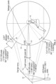
- the expanding light cone 20 from the projector 10 spreads the light rays away from the center of the image on the back of the screen 12. This is especially problematic when the screen 16 is curved as in a rear projected dome of a flight simulator as illustrated in Figure 2 .
- the screen 16 is concave on the observer/user 18 side, and convex on the projector 10 side of the screen 16.
- the spreading light rays combine with a screen 16 curving away from the projector to produce worsening resolution and brightness (e.g., stretching an image).
- a 50% reduction in resolution between the image center 24 (7.99 '/OLP) and image top 26 or bottom 28 (16.09 '/OLP) is shown in Figure 2 (given in Arcminutes / Optical Line Pair ('/OLP), which is the standard measure of resolution in training simulators with visual displays).
- '/OLP Arcminutes / Optical Line Pair
- a "20/20" visual resolution is approximately 2 ⁇ /OLP, where the smaller number indicates better resolution.
- Each of the image center 24, top 26 and bottom 28 shown in Figure 2 (and Figure 3 ) has a light cone of 100 pixels.
- FIG. 3 shows the effect of this image stretch from the perspective of the user 18 on a 100 pixel diameter circular object 24, 26, 28 (sun, moon, etc.) unless some image warping is applied. Such warping can only make the object circular again by using less than the original 100 pixels (thus reducing resolution of the image).
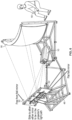
- Figures 4 and 5 show a free-form fold mirror 30 that overcomes the problems noted with the flat fold mirror 22.
- the free-form fold mirror 30 described herein would adjust the distribution of the projector's light rays onto the screen 16 to equalize the resolution across the image and produce a much more uniform resolution and brightness. In the example shown in Figures 4 and 5 , this would be accomplished by spreading the rays away from the image center and concentrating them towards the image boundaries or edges.
- the free-form fold mirror 30 includes a first, non-planar, curved portion 32 near the top of the mirror 30 (directional or positional terms such as “top,” “bottom,” “right,” etc. are used herein with respect to the locations or positions as shown in the Figures and are not meant to limit the invention to such locations or positions - that is the entire projector/mirror combination could be placed on its side or reversed with the projector on top - and still incorporate the invention at hand).
- the first curved portion 32 has a concave cross-sectional shape (i.e., with respect to the screen or the projected light cone).
- the free-form fold mirror 30 includes a flat portion 34 forming a central or middle portion of the mirror 30 below the first curved portion 32 and another flat portion 36 above the first curved portion 32.
- an outer (or leftmost) ray 38 of the light cone hitting the top portion of the free-form mirror 32 strikes the first curved portion 32 of the mirror 30 and is reflected toward the screen 16, and an inner (or rightmost) ray 40 of the light cone strikes the flat portion 36 above the first curved portion 32 and is also reflected toward the screen 16.
- This light cone is an upper 100 pixels of an image from the projector 10.
- Figure 5 also includes a flat fold mirror 22 superimposed in front of the free-form fold mirror 30. This is done to illustrate where the outer ray 38' of the light cone would reflect if the flat fold mirror 22 were used instead of the free-form fold mirror 32.
- each of the three images 24', 26' and 28' are 10.52 '/OLP as seen by the user 18 of the system.
- Figure 4 also shows a lower image (i.e., from the leftmost light cone emitted from the projector 10) formed by striking a second, non-planar, curved portion 42 on the free-form fold mirror 30.
- the second curved portion 42 is convex with respect to the light cone and the screen 16.
- Another flat portion 44 is adjacent the second curved portion 42 opposite the centrally located flat portion 34.
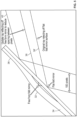
- a simulator display system having both mirrors 22, 30 is shown in Figure 6 .
- the two mirrors 22, 30 are both mounted to a support frame 46.
- the mirrors 22, 30 can slide to allow for either mirror to be in the projector's light path.
- the support frame 46 also holds a projector 10 and screen 16 (similar support frames are used to hold the components of the systems shown schematically in Figures 1-5 ).
- the entire system can be enclosed, and/or mounted on a moveable platform (that simulates movement of the airplane or other vehicle or machinery associated with the simulator).
- the free-form fold mirror 30 of the present invention is a departure from the typical flat, planar mirror, and will have a more complex shape than the flat mirror.
- the free-form fold mirror may be one or more mirror components connected or placed adjacent to each other.
- the free-form fold mirror 30 is shown in the Figures having two curved portions 32, 42, it can have fewer or more curved portions as necessary to provide any desired effects to the projected image. Moreover, the position and shape of the screen can affect the amount and positioning of any curved portions of such a mirror.
- a module may be a unit of distinct functionality that may be presented in software, hardware, or combinations thereof.
- the functionality of a module is performed in any part through software, the module includes a computer-readable medium.
- the modules may be regarded as being communicatively coupled.
- the inventive subject matter may be represented in a variety of different implementations of which there are many possible permutations.
- the machine operates as a standalone device or may be connected (e.g., networked) to other machines.
- the machine may operate in the capacity of a server or a client machine in server-client network environment, or as a peer machine in a peer-to-peer (or distributed) network environment.
- the machine may be a server computer, a client computer, a personal computer (PC), a tablet PC, a set-top box (STB), a Personal Digital Assistant (PDA), a cellular telephone, a web appliance, a network router, switch or bridge, or any machine capable of executing a set of instructions (sequential or otherwise) that specify actions to be taken by that machine or computing device.
- PC personal computer
- PDA Personal Digital Assistant
- a ray trace optimizer that includes a computer based software tool for modeling the ray traces and ultimately the free form shape of the fold mirror is utilized.
- the freeform mirror could be pre manufactured utilizing such a computer based tool.
- the free form mirror is dynamically adjusted with a mechanical push/pull system that mechanically deforms the reflective surface of the mirror to the appropriate curvature.
- the push/pull mechanism is computer controlled to adjust the curvature of the mirror based on other system parameters in order to reduce aberrations and improve resolution.
- the example computer system and client computers can include a processor (e.g., a central processing unit (CPU) a graphics processing unit (GPU) or both), a main memory and a static memory , which communicate with each other via a bus.
- the computer system may further include a video/graphical display unit (e.g., a liquid crystal display (LCD) or a cathode ray tube (CRT)).
- the computer system and client computing devices can also include an alphanumeric input device (e.g., a keyboard), a cursor control device (e.g., a mouse), a drive unit, a signal generation device (e.g., a speaker) and a network interface device.
- the drive unit includes a computer-readable medium on which is stored one or more sets of instructions (e.g., software) embodying any one or more of the methodologies or systems described herein.
- the software may also reside, completely or at least partially, within the main memory and/or within the processor during execution thereof by the computer system, the main memory and the processor also constituting computer-readable media.
- the software may further be transmitted or received over a network via the network interface device.
- computer-readable medium should be taken to include a single medium or multiple media (e.g., a centralized or distributed database, and/or associated caches and servers) that store the one or more sets of instructions.
- computer-readable medium shall also be taken to include any medium that is capable of storing or encoding a set of instructions for execution by the machine and that cause the machine to perform any one or more of the methodologies of the present implementation.
- computer-readable medium shall accordingly be taken to include, but not be limited to, solid-state memories, and optical media, and magnetic media.
Landscapes
- Physics & Mathematics (AREA)
- General Physics & Mathematics (AREA)
- Optics & Photonics (AREA)
- Engineering & Computer Science (AREA)
- Theoretical Computer Science (AREA)
- Manufacturing & Machinery (AREA)
- Aviation & Aerospace Engineering (AREA)
- Business, Economics & Management (AREA)
- Educational Administration (AREA)
- Educational Technology (AREA)
- Projection Apparatus (AREA)
- Transforming Electric Information Into Light Information (AREA)
Claims (15)
- Simulator-Projektions- oder -Anzeigesystem, aufweisend:einen Projektor (10);einen Anzeigebildschirm (12, 14, 16) zum Empfangen von Bildern von dem Projektor (10); undeinen Freiform-Faltspiegel (30), der zwischen dem Projektor (10) und dem Anzeigebildschirm (12, 14, 16) angeordnet ist,dadurch gekennzeichnet, dass
der Freiform-Faltspiegel (30) einen ersten gekrümmten Abschnitt (32), einen zweiten gekrümmten Abschnitt (42), der von dem ersten gekrümmten Abschnitt (32) beabstandet ist, und einen ersten flachen Abschnitt (34) aufweist. - Simulator-Projektions- oder -Anzeigesystem nach Anspruch 1, wobei der erste flache Abschnitt (34) zwischen dem ersten gekrümmten Abschnitt (32) und dem zweiten gekrümmten Abschnitt (42) liegt.
- Simulator-Projektions- oder -Anzeigesystem nach Anspruch 1 oder 2, wobei der erste flache Abschnitt (34) mittig positioniert ist, der erste gekrümmte Abschnitt (32) an eine obere Kante des ersten flachen Abschnitts (34) angrenzt und der zweite gekrümmte Abschnitt (42) an eine untere Kante des ersten flachen Abschnitts (34) angrenzt.
- Simulator-Projektions- oder -Anzeigesystem nach einem der vorhergehenden Ansprüche, wobei der erste gekrümmte Abschnitt (32) eine konkave Querschnittsform in Bezug auf den Anzeigebildschirm (12, 14, 16), insbesondere eine Rückfläche davon, aufweist, wobei vorzugsweise der zweite gekrümmte Abschnitt (42) eine konvexe Querschnittsform in Bezug auf den Anzeigebildschirm (12, 14, 16), insbesondere eine Rückfläche davon, aufweist.
- Simulator-Projektions- oder -Anzeigesystem nach einem der vorhergehenden Ansprüche, wobei der Projektor (10) konfiguriert ist, um ein hochauflösendes Bild zu projizieren.
- Simulator-Projektions- oder -Anzeigesystem nach einem der vorhergehenden Ansprüche, wobei der Anzeigebildschirm (12, 14, 16) gekrümmt ist.
- Simulator-Projektions- oder -Anzeigesystem nach einem der vorhergehenden Ansprüche, wobei der erste gekrümmte Abschnitt (32) positioniert ist, um eine Kante eines Bildes von dem Projektor (10) zu beeinflussen.
- Simulator-Projektions- oder -Anzeigesystem nach einem der vorhergehenden Ansprüche, ferner aufweisend einen zweiten flachen Abschnitt (36) in dem Freiform-Faltspiegel (30), wobei der erste gekrümmte Abschnitt (32) zwischen dem ersten flachen Abschnitt (34) und dem zweiten flachen Abschnitt (36) liegt.
- Simulator-Projektions- oder -Anzeigesystem nach Anspruch 8, ferner aufweisend einen dritten flachen Abschnitt (44) in dem Freiform-Faltspiegel (30), wobei der zweite gekrümmte Abschnitt (42) zwischen dem ersten flachen Abschnitt (34) und dem dritten flachen Abschnitt (44) liegt.
- Simulator-Projektions- oder -Anzeigesystem nach einem der vorhergehenden Ansprüche, wobei der Anzeigebildschirm (12, 14, 16) Teil eines Flugsimulators ist.
- Verfahren zum Projizieren eines Bildes auf einen Anzeigebildschirm (12, 14, 16), aufweisend:Projizieren eines Bildes von einem Projektor (10) entlang eines Projektionspfades, der sich von einer Bildprojektionsquelle des Projektors (10) zu einem Spiegelschnittpunkt mit einem Freiform-Faltspiegel (30) erstreckt; undReflektieren des projizierten Bildes von dem Freiform-Faltspiegel (30) entlang eines Pfades, der sich von dem Freiform-Faltspiegel (30) zu einem Bildschirmschnittpunkt erstreckt, wobei der Freiform-Faltspiegel (30) zwischen dem Projektor (10) und dem Anzeigebildschirm (12, 14, 16) angeordnet ist,dadurch gekennzeichnet, dassder Freiform-Faltspiegel (30) einen ersten gekrümmten Abschnitt (32), einen ersten flachen Abschnitt (34) und einen zweiten gekrümmten Abschnitt (42), der von dem ersten gekrümmten Abschnitt (32) beabstandet ist, aufweist.
- Verfahren zum Projizieren eines Bildes nach Anspruch 11, wobei der erste flache Abschnitt (34) zwischen dem ersten gekrümmten Abschnitt (32) und dem zweiten gekrümmten Abschnitt (42) liegt.
- Verfahren zum Projizieren eines Bildes nach Anspruch 11 oder 12, wobei der erste gekrümmte Abschnitt (32) eine konkave Querschnittsform in Bezug auf den Anzeigebildschirm (12, 14, 16) aufweist, wobei vorzugsweise der zweite gekrümmte Abschnitt (42) eine konvexe Querschnittsform in Bezug auf den Anzeigebildschirm (12, 14, 16) aufweist.
- Verfahren zum Projizieren eines Bildes nach einem der Ansprüche 11 bis 13, wobei der Projektor (10) konfiguriert ist, um ein hochauflösendes Bild zu projizieren, und/oder wobei der Anzeigebildschirm (12, 14, 16) gekrümmt ist.
- Verfahren zum Projizieren eines Bildes nach einem der Ansprüche 11 bis 14, wobei der erste gekrümmte Abschnitt (32) positioniert ist, um eine Kante des Bildes von dem Projektor (10) zu beeinflussen.
Applications Claiming Priority (2)
| Application Number | Priority Date | Filing Date | Title |
|---|---|---|---|
| US201862769667P | 2018-11-20 | 2018-11-20 | |
| PCT/US2019/062485 WO2020106892A1 (en) | 2018-11-20 | 2019-11-20 | Rear projection simulator with freeform fold mirror |
Publications (3)
| Publication Number | Publication Date |
|---|---|
| EP3884343A1 EP3884343A1 (de) | 2021-09-29 |
| EP3884343A4 EP3884343A4 (de) | 2022-08-31 |
| EP3884343B1 true EP3884343B1 (de) | 2025-01-08 |
Family
ID=70726508
Family Applications (1)
| Application Number | Title | Priority Date | Filing Date |
|---|---|---|---|
| EP19887247.5A Active EP3884343B1 (de) | 2018-11-20 | 2019-11-20 | Rückprojektionssimulator mit freiformfaltspiegel |
Country Status (5)
| Country | Link |
|---|---|
| US (2) | US11029592B2 (de) |
| EP (1) | EP3884343B1 (de) |
| CN (1) | CN113424103B (de) |
| CA (1) | CA3120646A1 (de) |
| WO (1) | WO2020106892A1 (de) |
Families Citing this family (5)
| Publication number | Priority date | Publication date | Assignee | Title |
|---|---|---|---|---|
| US11122243B2 (en) | 2018-11-19 | 2021-09-14 | Flightsafety International Inc. | Method and apparatus for remapping pixel locations |
| EP3884343B1 (de) | 2018-11-20 | 2025-01-08 | FlightSafety International Inc. | Rückprojektionssimulator mit freiformfaltspiegel |
| US11681207B2 (en) | 2020-10-28 | 2023-06-20 | Flightsafety International Inc. | System and method of actively reducing an appearance of a seam in a mirror array |
| CA3237344A1 (en) * | 2021-11-15 | 2023-05-19 | Flightsafety International Inc. | System and method of adjusting focal distances of images displayed to a user of a simulator |
| US12374026B1 (en) * | 2024-01-31 | 2025-07-29 | Kenneth Epstein | Apparatus and method for generating and displaying three-dimensional images |
Family Cites Families (113)
| Publication number | Priority date | Publication date | Assignee | Title |
|---|---|---|---|---|
| US12003A (en) * | 1854-11-28 | Pianofokte-action | ||
| US2731883A (en) * | 1956-01-24 | Afocal anamorphotic cylindrical objective lens system | ||
| US2482115A (en) * | 1945-10-18 | 1949-09-20 | Jr Joseph P Laird | Optical projector and system |
| JPS5648851B2 (de) | 1973-12-27 | 1981-11-18 | ||
| US4129365A (en) * | 1977-05-13 | 1978-12-12 | Sperry Rand Corporation | Wide angle anamorphic display projection system |
| US4275962A (en) | 1978-12-28 | 1981-06-30 | Canon Kabushiki Kaisha | Projection device |
| US4234891A (en) * | 1979-07-30 | 1980-11-18 | The Singer Company | Optical illumination and distortion compensator |
| US4773748A (en) * | 1984-10-09 | 1988-09-27 | Hughes Aircraft Company | Dynamically controlled mirror for reduction of projected image distortion |
| JP2756514B2 (ja) * | 1988-12-09 | 1998-05-25 | ホシデン・フィリップス・ディスプレイ株式会社 | プロジェクション装置 |
| US4964718A (en) * | 1989-08-14 | 1990-10-23 | Mcdonnell Douglas Corporation | Optical corrector |
| US6631842B1 (en) * | 2000-06-07 | 2003-10-14 | Metrologic Instruments, Inc. | Method of and system for producing images of objects using planar laser illumination beams and image detection arrays |
| AU1393697A (en) * | 1996-01-17 | 1997-08-11 | Seos Displays Limited | An image projection display system for use in large field-of-view presentation |
| US5762413A (en) * | 1996-01-29 | 1998-06-09 | Alternate Realities Corporation | Tiltable hemispherical optical projection systems and methods having constant angular separation of projected pixels |
| US6231189B1 (en) * | 1996-01-29 | 2001-05-15 | Elumens Corporation | Dual polarization optical projection systems and methods |
| US5864431A (en) | 1997-07-07 | 1999-01-26 | Redifun Stimulation, Inc. | Method and apparatus for elimination of distortion in rear projection to curved surfaces |
| DE19737374C2 (de) * | 1997-08-27 | 1999-09-02 | Ldt Gmbh & Co | Verfahren zur Kompensation geometrischer Bildfehler bei Videobildern sowie ein Projektor zur Durchführung des Verfahrens |
| DE19809711C1 (de) | 1998-02-06 | 1999-11-18 | Rodenstock Praezisionsoptik Gm | Einblick- oder Einspiegelungseinrichtung |
| US6062696A (en) | 1998-03-13 | 2000-05-16 | Redifun Stimulation, Inc. | Play tunnel with surroundview display portals |
| US7112772B2 (en) | 1998-05-29 | 2006-09-26 | Carl Zeiss Smt Ag | Catadioptric projection objective with adaptive mirror and projection exposure method |
| WO2000070874A1 (en) | 1999-05-12 | 2000-11-23 | Redifun Stimulation, Inc. | Method and apparatus for an improved wide-angle display system |
| US6530667B1 (en) * | 2000-02-08 | 2003-03-11 | Elumens Corporation | Optical projection system including projection dome |
| US6610974B1 (en) * | 2000-06-05 | 2003-08-26 | Calient Networks, Inc. | Positioning a movable reflector in an optical switch |
| US6814578B2 (en) | 2002-04-11 | 2004-11-09 | The Boeing Company | Visual display system and method for displaying images utilizing a holographic collimator |
| DE10249338A1 (de) * | 2002-10-22 | 2004-05-19 | Jenoptik Ldt Gmbh | Anordnung zum Projizieren eines Bildes auf eine Projektionsfläche und zugehörige Transformationsoptik |
| US7090361B2 (en) | 2002-10-24 | 2006-08-15 | Barco N.V. | Bundled light based alignment and maintenance tool for projection systems |
| US6848792B1 (en) * | 2002-12-27 | 2005-02-01 | Barco N.V. | Full resolution multiple image projection system and method for projecting two images in full resolution adjacent each other |
| US7364313B2 (en) | 2002-12-27 | 2008-04-29 | Barco N.V. | Multiple image projection system and method for projecting multiple selected images adjacent each other |
| WO2004064370A2 (en) * | 2003-01-08 | 2004-07-29 | Silicon Optix Inc. | Image projection system and method |
| EP1450568A3 (de) | 2003-02-21 | 2009-08-26 | Barco N.V. | Verfahren zur Bildübertragung in einem Projektionssystem und Projektionssystem zur Durchführung des Verfahrens |
| EP1471746A3 (de) | 2003-03-31 | 2006-07-12 | Barco N.V. | Projektionseinrichtung und Lamplichtquellesystem für eine solche einrichtung |
| JP2004309684A (ja) * | 2003-04-04 | 2004-11-04 | Olympus Corp | 結像光学系及びそれを用いた撮像装置 |
| JP2004341519A (ja) | 2003-04-28 | 2004-12-02 | Barco Nv | 電子表示システムおよび電子表示装置の不揮発性電子表示機器上に画像を表示する方法 |
| EP1473687A3 (de) | 2003-04-28 | 2006-12-06 | Barco N.V. | Elektronisches Anzeigesystem und elektronische Anzeigevorrichtung |
| JP2005055909A (ja) | 2003-08-07 | 2005-03-03 | Barco Nv | Oledディスプレイ素子、それを制御するための制御装置、およびその耐用年数を最適化するための方法 |
| EP1505565A1 (de) | 2003-08-07 | 2005-02-09 | Barco N.V. | Verfahren und Vorrichtung zur Verbesserung der Lebensdauer einer OLED-Anzeige |
| US7262753B2 (en) | 2003-08-07 | 2007-08-28 | Barco N.V. | Method and system for measuring and controlling an OLED display element for improved lifetime and light output |
| US7012669B2 (en) * | 2003-08-18 | 2006-03-14 | Evans & Sutherland Computer Corporation | Reflection barrier for panoramic display |
| EP1513060A1 (de) | 2003-09-08 | 2005-03-09 | Barco N.V. | Pixeleinheit für Grossoberflächeanzeigevorrichtung und Steuerverfahren dafür |
| EP1536399A1 (de) | 2003-11-26 | 2005-06-01 | Barco N.V. | Methode und Vorrichtung zum visuellen Maskieren von Defekten in Matrix-Anzeigen unter Ausnutzung von Eigenschaften des menschlichen Auges |
| EP1548573A1 (de) | 2003-12-23 | 2005-06-29 | Barco N.V. | Hierarchische Steuerung für eine modulare leuchtende Grossbildschirm-Anzeige |
| EP1558042A3 (de) | 2004-01-20 | 2006-06-07 | Barco N.V. | Projektionssystem unter Verwendung mehrerer Lichtquellen |
| US6984042B2 (en) | 2004-02-24 | 2006-01-10 | Barco N.V. | Convergence system for a projection display system |
| US7192141B2 (en) | 2004-02-24 | 2007-03-20 | Barco N.V. | Optical arrangement for non-inverting illumination system |
| US20050286144A1 (en) | 2004-06-28 | 2005-12-29 | Koen Malfait | Method and device for improving contrast in a projection system |
| JP2006171722A (ja) | 2004-11-30 | 2006-06-29 | Barco Nv | カラーディスプレイ、マルチディスプレイシステム、調節装置、ならびにカラーディスプレイを設定および/または調節するための方法 |
| US7647567B1 (en) | 2005-01-31 | 2010-01-12 | Bluespec, Inc. | System and method for scheduling TRS rules |
| US7766483B2 (en) | 2005-04-06 | 2010-08-03 | Suresh Balu | Optical projection system and methods for configuring the same |
| RU2322771C2 (ru) | 2005-04-25 | 2008-04-20 | Святослав Иванович АРСЕНИЧ | Стереопроекционная система |
| WO2007049263A1 (en) | 2005-10-27 | 2007-05-03 | Optyka Limited | An image projection display system |
| JP4933083B2 (ja) * | 2005-11-04 | 2012-05-16 | 株式会社日立製作所 | 投写型映像表示装置とその投写光学ユニット |
| US20160357094A1 (en) * | 2005-11-23 | 2016-12-08 | Fusao Ishii | Optics of projecor |
| US20070120763A1 (en) | 2005-11-23 | 2007-05-31 | Lode De Paepe | Display system for viewing multiple video signals |
| EP1808840B1 (de) | 2006-01-13 | 2020-03-04 | Barco N.V. | Verfahren und Vorrichtung zum Schattieren in einem Anzeigesystem |
| JP2007272061A (ja) | 2006-03-31 | 2007-10-18 | Denso Corp | ヘッドアップディスプレイ装置 |
| WO2007149333A2 (en) * | 2006-06-16 | 2007-12-27 | Alphacurve, Inc. | Curved screen display system and method |
| US20080123062A1 (en) | 2006-11-28 | 2008-05-29 | Seiko Epson Corporation | Projector |
| DE102007005168A1 (de) * | 2007-01-29 | 2008-07-31 | Ruped Systems Gmbh | Anastigmatisches anamorphotisches Objektiv |
| US20080204666A1 (en) * | 2007-02-02 | 2008-08-28 | Robert Spearman | Image projection and capture systems |
| JP2008287114A (ja) * | 2007-05-18 | 2008-11-27 | Sony Corp | 画像投射装置及び画像投射方法 |
| GB0711632D0 (en) | 2007-06-18 | 2007-07-25 | Barco Nv | Method and device for shading in a display system |
| EP2015589A1 (de) | 2007-07-13 | 2009-01-14 | Barco NV | Stereoanzeigesystem mit Abtastung von Lichtventilen |
| US8319699B2 (en) | 2007-08-09 | 2012-11-27 | Barco N.V. | Multiple display channel system with high dynamic range |
| US8128238B2 (en) * | 2007-09-07 | 2012-03-06 | Ricoh Company, Ltd. | Projection optical system and image displaying apparatus |
| US9188850B2 (en) * | 2007-09-10 | 2015-11-17 | L-3 Communications Corporation | Display system for high-definition projectors |
| CN101971075A (zh) * | 2007-12-18 | 2011-02-09 | 光处方革新有限公司 | 自由形态聚光光学装置 |
| KR100888922B1 (ko) | 2007-12-27 | 2009-03-16 | 주식회사 나노포토닉스 | 어안 렌즈 |
| US8194193B2 (en) * | 2008-02-08 | 2012-06-05 | The Boeing Company | Method and apparatus for a wide field of view display |
| EP2096618B1 (de) | 2008-02-28 | 2013-10-23 | Barco NV | Klemmsystem für Anzeigevorrichtungen |
| EP2159783A1 (de) | 2008-09-01 | 2010-03-03 | Barco N.V. | Verfahren und System zum Kompensieren von Alterungseffekten bei LED-Anzeigevorrichtungen |
| US8403503B1 (en) * | 2009-02-12 | 2013-03-26 | Zheng Jason Geng | Freeform optical device and short standoff image projection |
| JP2011242580A (ja) | 2010-05-18 | 2011-12-01 | Olympus Corp | 投影光学装置 |
| GB2482289B (en) | 2010-07-26 | 2016-04-06 | Barco Nv | Position adjustment system for a projection lens |
| GB201016566D0 (en) | 2010-10-01 | 2010-11-17 | Barco Nv | Curved back projection screen |
| GB2486921A (en) | 2010-12-31 | 2012-07-04 | Barco Nv | Compensating for age effects in active matrix displays |
| DE102011053630B4 (de) | 2011-09-15 | 2019-11-21 | Carl Zeiss Microscopy Gmbh | Verfahren und Vorrichtung zur Bildstabilisierung in einem optischen Beobachtungs- oder Messgerät |
| JP6007478B2 (ja) | 2011-11-02 | 2016-10-12 | 株式会社リコー | 画像表示装置 |
| US9436074B2 (en) | 2012-01-15 | 2016-09-06 | Barco Nv | Projection system and method of projecting multiple images |
| WO2013164015A1 (en) | 2012-04-30 | 2013-11-07 | Barco N.V. | A display integrated semitransparent sensor system and use thereof |
| US10073336B2 (en) | 2012-09-11 | 2018-09-11 | Barco N.V. | Projection system with safety detection |
| GB2505708B (en) | 2012-09-11 | 2015-02-25 | Barco Nv | Projection system with safety detection |
| US9158119B2 (en) * | 2012-10-31 | 2015-10-13 | Ricoh Company, Ltd. | Enlargement optical system |
| GB2496534B (en) | 2013-01-14 | 2013-10-09 | Stromberg Ind Aps | Rear screen projection apparatus and method |
| CN105074568B (zh) * | 2013-04-16 | 2019-01-08 | 图象公司 | 短屏幕距离中的双投影 |
| US9110358B1 (en) * | 2013-06-04 | 2015-08-18 | The Boeing Company | Method for creating and a system for using a constant vertical resolution toroidal display |
| EP2837968A1 (de) | 2013-08-14 | 2015-02-18 | Barco N.V. | Projektor und Anzeigesystem damit |
| GB2522175A (en) | 2013-10-31 | 2015-07-22 | Barco Nv | Display system |
| JP6283993B2 (ja) * | 2013-11-20 | 2018-02-28 | 株式会社リコー | 投射光学装置及び画像投射装置 |
| WO2015074695A1 (en) * | 2013-11-21 | 2015-05-28 | Barco N.V. | Method for controlling an illumination system |
| GB201321305D0 (en) | 2013-12-03 | 2014-01-15 | Barco Nv | Projection subsystem for high contrast projection system |
| EP3127328B1 (de) | 2014-04-04 | 2023-05-17 | Barco N.V. | Laserprojektionbeleuchtungssystem |
| JP5930231B2 (ja) * | 2014-08-20 | 2016-06-08 | 日本精機株式会社 | 投影装置及びヘッドアップディスプレイ装置 |
| US9436068B2 (en) * | 2014-09-17 | 2016-09-06 | The Boeing Company | Portable constant resolution visual system (CRVS) with defined throw distance |
| US9940909B2 (en) | 2014-10-14 | 2018-04-10 | Barco N.V. | Display system with a virtual display |
| EP3024176A1 (de) | 2014-11-21 | 2016-05-25 | Alcatel Lucent | Verfahren zur Beurteilung der Dienstqualität einer Datenkommunikation über eine Datenkommunikationsleitung, zugehöriges System und Vorrichtungen |
| CN107743612A (zh) | 2015-04-13 | 2018-02-27 | 巴科股份有限公司 | 用于显示图像数据的基于浏览器的显示系统 |
| JP6604090B2 (ja) * | 2015-08-27 | 2019-11-13 | 株式会社リコー | 投射光学系および投射装置および投射システム |
| US10685580B2 (en) * | 2015-12-31 | 2020-06-16 | Flightsafety International Inc. | Apparatus, engine, system and method of providing simulation of and training for the operation of heavy equipment |
| EP3415974B1 (de) * | 2016-02-08 | 2021-03-24 | Nippon Seiki Co., Ltd. | Anzeigevorrichtung und head-up-anzeige |
| US20170262020A1 (en) * | 2016-03-10 | 2017-09-14 | The Void Llc | Head Mount Display with Near-Eye Projection for Virtual Reality System |
| US10169846B2 (en) | 2016-03-31 | 2019-01-01 | Sony Interactive Entertainment Inc. | Selective peripheral vision filtering in a foveated rendering system |
| WO2017178519A1 (en) | 2016-04-13 | 2017-10-19 | Barco N.V. | Display system for displaying image data |
| GB201612341D0 (en) | 2016-07-15 | 2016-08-31 | Barco N V And Barco Fredrikstad As | Projection System and Method For Improved Color Performance |
| WO2018019369A1 (en) | 2016-07-27 | 2018-02-01 | Barco N.V. | Projection screen system and method for implementation |
| CN107664910A (zh) | 2016-07-29 | 2018-02-06 | 巴科股份有限公司 | 无缝多屏投影显示系统 |
| GB2558299A (en) | 2016-12-29 | 2018-07-11 | Barco Nv | Method and system for managing ageing effects in light emitting diode displays |
| US20180192017A1 (en) | 2016-12-30 | 2018-07-05 | Barco N.V. | Apparatus and methods for detection and evaluation of failures in a display system |
| EP3577516B1 (de) | 2017-02-03 | 2025-11-12 | Barco N.V. | System und verfahren zur verbesserten bildprojektion |
| US11074028B2 (en) | 2017-07-26 | 2021-07-27 | Barco N.V. | Calibration method and system for tiled displays |
| GB2566312B (en) | 2017-09-08 | 2021-12-29 | Barco Nv | Method and system for reducing reflection of ambient light in an emissive display |
| GB201805349D0 (en) | 2018-03-30 | 2018-05-16 | Barco Nv | Inflatable light diverging mirror and method for making the same |
| EP3599495A1 (de) | 2018-07-24 | 2020-01-29 | ScioTeq BVBA | Kollimiertes visuelles anzeigesystem |
| US11122243B2 (en) | 2018-11-19 | 2021-09-14 | Flightsafety International Inc. | Method and apparatus for remapping pixel locations |
| EP3884343B1 (de) * | 2018-11-20 | 2025-01-08 | FlightSafety International Inc. | Rückprojektionssimulator mit freiformfaltspiegel |
-
2019
- 2019-11-20 EP EP19887247.5A patent/EP3884343B1/de active Active
- 2019-11-20 US US16/689,866 patent/US11029592B2/en active Active
- 2019-11-20 WO PCT/US2019/062485 patent/WO2020106892A1/en not_active Ceased
- 2019-11-20 CA CA3120646A patent/CA3120646A1/en active Pending
- 2019-11-20 CN CN201980087084.8A patent/CN113424103B/zh active Active
-
2021
- 2021-06-07 US US17/341,081 patent/US11709418B2/en active Active
Also Published As
| Publication number | Publication date |
|---|---|
| WO2020106892A1 (en) | 2020-05-28 |
| CN113424103B (zh) | 2023-07-18 |
| US20210294199A1 (en) | 2021-09-23 |
| EP3884343A4 (de) | 2022-08-31 |
| CN113424103A (zh) | 2021-09-21 |
| US11709418B2 (en) | 2023-07-25 |
| US11029592B2 (en) | 2021-06-08 |
| CA3120646A1 (en) | 2020-05-28 |
| US20200159104A1 (en) | 2020-05-21 |
| EP3884343A1 (de) | 2021-09-29 |
Similar Documents
| Publication | Publication Date | Title |
|---|---|---|
| EP3884343B1 (de) | Rückprojektionssimulator mit freiformfaltspiegel | |
| US12192686B2 (en) | Method and apparatus for remapping pixel locations | |
| CN112913231B (zh) | 一种计算机实施的方法、计算机可读介质和数字显示设备 | |
| KR102478370B1 (ko) | 광학적 렌즈 왜곡을 교정하기 위한 동공 위치의 사용 | |
| US20080204666A1 (en) | Image projection and capture systems | |
| WO2019171334A1 (en) | Vision correction system and method, light field display and light field shaping layer and alignment therefor | |
| US9470967B1 (en) | Motion-based system using a constant vertical resolution toroidal display | |
| US8564622B1 (en) | Image generation device for generating multiple image streams | |
| JP2023523098A (ja) | 均一な放射照度の拡張光源フリーフォーム | |
| US11353699B2 (en) | Vision correction system and method, light field display and light field shaping layer and alignment therefor |
Legal Events
| Date | Code | Title | Description |
|---|---|---|---|
| STAA | Information on the status of an ep patent application or granted ep patent |
Free format text: STATUS: THE INTERNATIONAL PUBLICATION HAS BEEN MADE |
|
| PUAI | Public reference made under article 153(3) epc to a published international application that has entered the european phase |
Free format text: ORIGINAL CODE: 0009012 |
|
| STAA | Information on the status of an ep patent application or granted ep patent |
Free format text: STATUS: REQUEST FOR EXAMINATION WAS MADE |
|
| 17P | Request for examination filed |
Effective date: 20210617 |
|
| AK | Designated contracting states |
Kind code of ref document: A1 Designated state(s): AL AT BE BG CH CY CZ DE DK EE ES FI FR GB GR HR HU IE IS IT LI LT LU LV MC MK MT NL NO PL PT RO RS SE SI SK SM TR |
|
| DAV | Request for validation of the european patent (deleted) | ||
| DAX | Request for extension of the european patent (deleted) | ||
| A4 | Supplementary search report drawn up and despatched |
Effective date: 20220802 |
|
| RIC1 | Information provided on ipc code assigned before grant |
Ipc: G03B 21/13 20060101ALN20220727BHEP Ipc: G03B 21/606 20140101ALN20220727BHEP Ipc: G02B 27/01 20060101ALN20220727BHEP Ipc: G02B 5/10 20060101ALI20220727BHEP Ipc: G09B 9/32 20060101ALI20220727BHEP Ipc: G03B 21/62 20140101ALI20220727BHEP Ipc: G03B 21/28 20060101AFI20220727BHEP |
|
| GRAP | Despatch of communication of intention to grant a patent |
Free format text: ORIGINAL CODE: EPIDOSNIGR1 |
|
| RIN1 | Information on inventor provided before grant (corrected) |
Inventor name: KNAPLUND, JUSTIN KING Inventor name: SPIEGELMAN, ADAM KRISTOPHER |
|
| STAA | Information on the status of an ep patent application or granted ep patent |
Free format text: STATUS: GRANT OF PATENT IS INTENDED |
|
| RAP3 | Party data changed (applicant data changed or rights of an application transferred) |
Owner name: FLIGHTSAFETY INTERNATIONAL INC. |
|
| RIC1 | Information provided on ipc code assigned before grant |
Ipc: G03B 21/13 20060101ALN20240726BHEP Ipc: G03B 21/606 20140101ALN20240726BHEP Ipc: G02B 27/01 20060101ALN20240726BHEP Ipc: G02B 5/10 20060101ALI20240726BHEP Ipc: G09B 9/32 20060101ALI20240726BHEP Ipc: G03B 21/62 20140101ALI20240726BHEP Ipc: G03B 21/28 20060101AFI20240726BHEP |
|
| INTG | Intention to grant announced |
Effective date: 20240808 |
|
| GRAS | Grant fee paid |
Free format text: ORIGINAL CODE: EPIDOSNIGR3 |
|
| GRAA | (expected) grant |
Free format text: ORIGINAL CODE: 0009210 |
|
| STAA | Information on the status of an ep patent application or granted ep patent |
Free format text: STATUS: THE PATENT HAS BEEN GRANTED |
|
| AK | Designated contracting states |
Kind code of ref document: B1 Designated state(s): AL AT BE BG CH CY CZ DE DK EE ES FI FR GB GR HR HU IE IS IT LI LT LU LV MC MK MT NL NO PL PT RO RS SE SI SK SM TR |
|
| REG | Reference to a national code |
Ref country code: GB Ref legal event code: FG4D |
|
| REG | Reference to a national code |
Ref country code: CH Ref legal event code: EP |
|
| REG | Reference to a national code |
Ref country code: DE Ref legal event code: R096 Ref document number: 602019064742 Country of ref document: DE |
|
| REG | Reference to a national code |
Ref country code: IE Ref legal event code: FG4D |
|
| P01 | Opt-out of the competence of the unified patent court (upc) registered |
Free format text: CASE NUMBER: APP_1585/2025 Effective date: 20250110 |
|
| REG | Reference to a national code |
Ref country code: LT Ref legal event code: MG9D |
|
| REG | Reference to a national code |
Ref country code: NL Ref legal event code: MP Effective date: 20250108 |
|
| REG | Reference to a national code |
Ref country code: AT Ref legal event code: MK05 Ref document number: 1758723 Country of ref document: AT Kind code of ref document: T Effective date: 20250108 |
|
| PG25 | Lapsed in a contracting state [announced via postgrant information from national office to epo] |
Ref country code: NL Free format text: LAPSE BECAUSE OF FAILURE TO SUBMIT A TRANSLATION OF THE DESCRIPTION OR TO PAY THE FEE WITHIN THE PRESCRIBED TIME-LIMIT Effective date: 20250108 |
|
| PG25 | Lapsed in a contracting state [announced via postgrant information from national office to epo] |
Ref country code: RS Free format text: LAPSE BECAUSE OF FAILURE TO SUBMIT A TRANSLATION OF THE DESCRIPTION OR TO PAY THE FEE WITHIN THE PRESCRIBED TIME-LIMIT Effective date: 20250408 |
|
| PG25 | Lapsed in a contracting state [announced via postgrant information from national office to epo] |
Ref country code: FI Free format text: LAPSE BECAUSE OF FAILURE TO SUBMIT A TRANSLATION OF THE DESCRIPTION OR TO PAY THE FEE WITHIN THE PRESCRIBED TIME-LIMIT Effective date: 20250108 |
|
| PG25 | Lapsed in a contracting state [announced via postgrant information from national office to epo] |
Ref country code: PL Free format text: LAPSE BECAUSE OF FAILURE TO SUBMIT A TRANSLATION OF THE DESCRIPTION OR TO PAY THE FEE WITHIN THE PRESCRIBED TIME-LIMIT Effective date: 20250108 |
|
| PG25 | Lapsed in a contracting state [announced via postgrant information from national office to epo] |
Ref country code: ES Free format text: LAPSE BECAUSE OF FAILURE TO SUBMIT A TRANSLATION OF THE DESCRIPTION OR TO PAY THE FEE WITHIN THE PRESCRIBED TIME-LIMIT Effective date: 20250108 |
|
| PG25 | Lapsed in a contracting state [announced via postgrant information from national office to epo] |
Ref country code: IS Free format text: LAPSE BECAUSE OF FAILURE TO SUBMIT A TRANSLATION OF THE DESCRIPTION OR TO PAY THE FEE WITHIN THE PRESCRIBED TIME-LIMIT Effective date: 20250508 Ref country code: NO Free format text: LAPSE BECAUSE OF FAILURE TO SUBMIT A TRANSLATION OF THE DESCRIPTION OR TO PAY THE FEE WITHIN THE PRESCRIBED TIME-LIMIT Effective date: 20250408 |
|
| PG25 | Lapsed in a contracting state [announced via postgrant information from national office to epo] |
Ref country code: HR Free format text: LAPSE BECAUSE OF FAILURE TO SUBMIT A TRANSLATION OF THE DESCRIPTION OR TO PAY THE FEE WITHIN THE PRESCRIBED TIME-LIMIT Effective date: 20250108 |
|
| PG25 | Lapsed in a contracting state [announced via postgrant information from national office to epo] |
Ref country code: LV Free format text: LAPSE BECAUSE OF FAILURE TO SUBMIT A TRANSLATION OF THE DESCRIPTION OR TO PAY THE FEE WITHIN THE PRESCRIBED TIME-LIMIT Effective date: 20250108 Ref country code: PT Free format text: LAPSE BECAUSE OF FAILURE TO SUBMIT A TRANSLATION OF THE DESCRIPTION OR TO PAY THE FEE WITHIN THE PRESCRIBED TIME-LIMIT Effective date: 20250508 |
|
| PG25 | Lapsed in a contracting state [announced via postgrant information from national office to epo] |
Ref country code: BG Free format text: LAPSE BECAUSE OF FAILURE TO SUBMIT A TRANSLATION OF THE DESCRIPTION OR TO PAY THE FEE WITHIN THE PRESCRIBED TIME-LIMIT Effective date: 20250108 Ref country code: GR Free format text: LAPSE BECAUSE OF FAILURE TO SUBMIT A TRANSLATION OF THE DESCRIPTION OR TO PAY THE FEE WITHIN THE PRESCRIBED TIME-LIMIT Effective date: 20250409 |
|
| PG25 | Lapsed in a contracting state [announced via postgrant information from national office to epo] |
Ref country code: AT Free format text: LAPSE BECAUSE OF FAILURE TO SUBMIT A TRANSLATION OF THE DESCRIPTION OR TO PAY THE FEE WITHIN THE PRESCRIBED TIME-LIMIT Effective date: 20250108 |
|
| PG25 | Lapsed in a contracting state [announced via postgrant information from national office to epo] |
Ref country code: SE Free format text: LAPSE BECAUSE OF FAILURE TO SUBMIT A TRANSLATION OF THE DESCRIPTION OR TO PAY THE FEE WITHIN THE PRESCRIBED TIME-LIMIT Effective date: 20250108 |
|
| PG25 | Lapsed in a contracting state [announced via postgrant information from national office to epo] |
Ref country code: SM Free format text: LAPSE BECAUSE OF FAILURE TO SUBMIT A TRANSLATION OF THE DESCRIPTION OR TO PAY THE FEE WITHIN THE PRESCRIBED TIME-LIMIT Effective date: 20250108 |
|
| REG | Reference to a national code |
Ref country code: DE Ref legal event code: R097 Ref document number: 602019064742 Country of ref document: DE |
|
| PG25 | Lapsed in a contracting state [announced via postgrant information from national office to epo] |
Ref country code: DK Free format text: LAPSE BECAUSE OF FAILURE TO SUBMIT A TRANSLATION OF THE DESCRIPTION OR TO PAY THE FEE WITHIN THE PRESCRIBED TIME-LIMIT Effective date: 20250108 |
|
| PG25 | Lapsed in a contracting state [announced via postgrant information from national office to epo] |
Ref country code: EE Free format text: LAPSE BECAUSE OF FAILURE TO SUBMIT A TRANSLATION OF THE DESCRIPTION OR TO PAY THE FEE WITHIN THE PRESCRIBED TIME-LIMIT Effective date: 20250108 Ref country code: CZ Free format text: LAPSE BECAUSE OF FAILURE TO SUBMIT A TRANSLATION OF THE DESCRIPTION OR TO PAY THE FEE WITHIN THE PRESCRIBED TIME-LIMIT Effective date: 20250108 |
|
| PG25 | Lapsed in a contracting state [announced via postgrant information from national office to epo] |
Ref country code: RO Free format text: LAPSE BECAUSE OF FAILURE TO SUBMIT A TRANSLATION OF THE DESCRIPTION OR TO PAY THE FEE WITHIN THE PRESCRIBED TIME-LIMIT Effective date: 20250108 |
|
| PG25 | Lapsed in a contracting state [announced via postgrant information from national office to epo] |
Ref country code: SK Free format text: LAPSE BECAUSE OF FAILURE TO SUBMIT A TRANSLATION OF THE DESCRIPTION OR TO PAY THE FEE WITHIN THE PRESCRIBED TIME-LIMIT Effective date: 20250108 |
|
| PLBE | No opposition filed within time limit |
Free format text: ORIGINAL CODE: 0009261 |
|
| STAA | Information on the status of an ep patent application or granted ep patent |
Free format text: STATUS: NO OPPOSITION FILED WITHIN TIME LIMIT |
|
| 26N | No opposition filed |
Effective date: 20251009 |
|
| PGFP | Annual fee paid to national office [announced via postgrant information from national office to epo] |
Ref country code: GB Payment date: 20251022 Year of fee payment: 7 |
|
| PGFP | Annual fee paid to national office [announced via postgrant information from national office to epo] |
Ref country code: BE Payment date: 20251022 Year of fee payment: 7 |
|
| PG25 | Lapsed in a contracting state [announced via postgrant information from national office to epo] |
Ref country code: IT Free format text: LAPSE BECAUSE OF FAILURE TO SUBMIT A TRANSLATION OF THE DESCRIPTION OR TO PAY THE FEE WITHIN THE PRESCRIBED TIME-LIMIT Effective date: 20250108 |