EP3024176A1 - Verfahren zur Beurteilung der Dienstqualität einer Datenkommunikation über eine Datenkommunikationsleitung, zugehöriges System und Vorrichtungen - Google Patents
Verfahren zur Beurteilung der Dienstqualität einer Datenkommunikation über eine Datenkommunikationsleitung, zugehöriges System und Vorrichtungen Download PDFInfo
- Publication number
- EP3024176A1 EP3024176A1 EP14306855.9A EP14306855A EP3024176A1 EP 3024176 A1 EP3024176 A1 EP 3024176A1 EP 14306855 A EP14306855 A EP 14306855A EP 3024176 A1 EP3024176 A1 EP 3024176A1
- Authority
- EP
- European Patent Office
- Prior art keywords
- quality
- service
- line
- data communications
- communications line
- Prior art date
- Legal status (The legal status is an assumption and is not a legal conclusion. Google has not performed a legal analysis and makes no representation as to the accuracy of the status listed.)
- Withdrawn
Links
- 238000004891 communication Methods 0.000 title claims abstract description 144
- 238000000034 method Methods 0.000 title claims abstract description 63
- 238000005516 engineering process Methods 0.000 claims abstract description 11
- 230000008878 coupling Effects 0.000 claims abstract description 7
- 238000010168 coupling process Methods 0.000 claims abstract description 7
- 238000005859 coupling reaction Methods 0.000 claims abstract description 7
- 230000009471 action Effects 0.000 claims description 21
- 238000012806 monitoring device Methods 0.000 claims description 12
- 238000001303 quality assessment method Methods 0.000 claims description 7
- 238000004590 computer program Methods 0.000 claims description 6
- 101100189060 Arabidopsis thaliana PROC1 gene Proteins 0.000 claims description 2
- 238000007726 management method Methods 0.000 description 26
- 230000002354 daily effect Effects 0.000 description 19
- OEBXWWBYZJNKRK-UHFFFAOYSA-N 1-methyl-2,3,4,6,7,8-hexahydropyrimido[1,2-a]pyrimidine Chemical compound C1CCN=C2N(C)CCCN21 OEBXWWBYZJNKRK-UHFFFAOYSA-N 0.000 description 17
- 230000005540 biological transmission Effects 0.000 description 12
- 238000012937 correction Methods 0.000 description 10
- 230000000875 corresponding effect Effects 0.000 description 8
- 238000005457 optimization Methods 0.000 description 7
- 238000010586 diagram Methods 0.000 description 6
- 230000006872 improvement Effects 0.000 description 6
- 230000008569 process Effects 0.000 description 6
- 238000013024 troubleshooting Methods 0.000 description 6
- 101100042631 Saccharomyces cerevisiae (strain ATCC 204508 / S288c) SIN3 gene Proteins 0.000 description 4
- 230000006735 deficit Effects 0.000 description 4
- 230000003116 impacting effect Effects 0.000 description 4
- 230000015556 catabolic process Effects 0.000 description 3
- 238000006731 degradation reaction Methods 0.000 description 3
- 230000007246 mechanism Effects 0.000 description 3
- 238000011002 quantification Methods 0.000 description 3
- 101000617546 Homo sapiens Presenilin-2 Proteins 0.000 description 2
- 102100022036 Presenilin-2 Human genes 0.000 description 2
- 238000013459 approach Methods 0.000 description 2
- 230000008901 benefit Effects 0.000 description 2
- 238000012544 monitoring process Methods 0.000 description 2
- 230000006641 stabilisation Effects 0.000 description 2
- 230000000007 visual effect Effects 0.000 description 2
- 102100032919 Chromobox protein homolog 1 Human genes 0.000 description 1
- 101000797584 Homo sapiens Chromobox protein homolog 1 Proteins 0.000 description 1
- 101150012532 NANOG gene Proteins 0.000 description 1
- 101100396520 Saccharomyces cerevisiae (strain ATCC 204508 / S288c) TIF3 gene Proteins 0.000 description 1
- 230000002411 adverse Effects 0.000 description 1
- 239000004020 conductor Substances 0.000 description 1
- 230000001276 controlling effect Effects 0.000 description 1
- 230000002596 correlated effect Effects 0.000 description 1
- 238000003066 decision tree Methods 0.000 description 1
- 230000000593 degrading effect Effects 0.000 description 1
- 238000001514 detection method Methods 0.000 description 1
- 238000003745 diagnosis Methods 0.000 description 1
- 230000000694 effects Effects 0.000 description 1
- 230000003203 everyday effect Effects 0.000 description 1
- 239000004065 semiconductor Substances 0.000 description 1
- 230000002269 spontaneous effect Effects 0.000 description 1
- 238000011105 stabilization Methods 0.000 description 1
- 101150038107 stm1 gene Proteins 0.000 description 1
- 230000001052 transient effect Effects 0.000 description 1
- 230000007704 transition Effects 0.000 description 1
Images


Classifications
-
- H—ELECTRICITY
- H04—ELECTRIC COMMUNICATION TECHNIQUE
- H04B—TRANSMISSION
- H04B3/00—Line transmission systems
- H04B3/02—Details
- H04B3/46—Monitoring; Testing
-
- H—ELECTRICITY
- H04—ELECTRIC COMMUNICATION TECHNIQUE
- H04L—TRANSMISSION OF DIGITAL INFORMATION, e.g. TELEGRAPHIC COMMUNICATION
- H04L41/00—Arrangements for maintenance, administration or management of data switching networks, e.g. of packet switching networks
- H04L41/50—Network service management, e.g. ensuring proper service fulfilment according to agreements
- H04L41/5003—Managing SLA; Interaction between SLA and QoS
- H04L41/5009—Determining service level performance parameters or violations of service level contracts, e.g. violations of agreed response time or mean time between failures [MTBF]
-
- H—ELECTRICITY
- H04—ELECTRIC COMMUNICATION TECHNIQUE
- H04L—TRANSMISSION OF DIGITAL INFORMATION, e.g. TELEGRAPHIC COMMUNICATION
- H04L43/00—Arrangements for monitoring or testing data switching networks
- H04L43/08—Monitoring or testing based on specific metrics, e.g. QoS, energy consumption or environmental parameters
- H04L43/0876—Network utilisation, e.g. volume of load or congestion level
- H04L43/0888—Throughput
-
- H—ELECTRICITY
- H04—ELECTRIC COMMUNICATION TECHNIQUE
- H04L—TRANSMISSION OF DIGITAL INFORMATION, e.g. TELEGRAPHIC COMMUNICATION
- H04L41/00—Arrangements for maintenance, administration or management of data switching networks, e.g. of packet switching networks
- H04L41/50—Network service management, e.g. ensuring proper service fulfilment according to agreements
- H04L41/5032—Generating service level reports
Definitions
- the present invention relates to the performance monitoring of an access network including Digital Subscriber Line (DSL) connections and in particular, but not exclusively relates to assessing a quality of service of a data communication over a data communications line.
- DSL Digital Subscriber Line
- DSL Digital Subscriber Lines
- DLM Dynamic Line Management
- ADSLx technology use frequencies up to about 1.1 MHz.
- VDSL2 technology can be applied with bandwidths up to 17 MHz or even 30 MHz.
- dynamic line management monitors at least one parameter describing a physical characteristic of one or more digital subscriber lines and thereby dynamically accesses and monitors the stability of the line.
- a line is considered stable if transmission at a certain bit rate can be maintained during a sufficiently long time interval. Otherwise, the line is considered as unstable. Unstable lines typically have an unacceptable high rate of resynchronisations or an unacceptable high rate of coding violations or other transmission errors. If dynamic line management detects that a certain line is unstable, the maximum bit rate of that line may be reduced in order to stabilize that line.
- the quality of service (e. g. the bit rate under the stability assumption) should be improved and any unneeded decrease of the quality of service seen by the end user should be avoided.
- dynamic line management should not operate too conservatively and classify a line as unstable although the user does not feel any practical impacts on the quality of service, because a stabilisation action would typically reduce the bit rate or the latency of the line.
- metrics and associated thresholds have been defined.
- Exemplary known metrics are the Mean Time Between Errors (MTBE) and the Mean Time Between Resynchronizations (MTBR).
- the Mean Time Between Errors MTBE describes a mean time during which a line has to wait before the transmission on that line is degraded by corrupted symbols, i.e. by physical layer symbols containing errors that may be caused by impulse noise or other disturbances.
- the mean time between Resynchronizations MTBR describes a mean time before the modems of the customer premises equipment (CPE) and an access node of the network (e.g. a DSLAM) resynchronise spontaneously because of a weak quality of the link.
- CPE customer premises equipment
- DSLAM access node of the network
- An objective of embodiments of the present invention is to provide with a method and related devices for assessment of the Quality of Service of a data communication over a data communications line of the above known type but wherein the assessment of the Quality of Service provides with a better indication of the real Quality of Service situation.
- a method for assessing a Quality of Service of a data communication over a data communications line comprising the steps of collecting, for said data communications line, physical error free throughput information and assessing or estimating for said data communications line a minimum error-free physical line throughput and generating a Quality of service classification of said data communications line based on said minimum error-free physical line throughput.
- this classification may be provide with an improved indication of the real Quality of Service situation.
- the collecting of the physical line data, i.e. the minimum error-free physical line throughput may comprise retrieving the physical line data from at least one network element where the physical line data is collected.
- this network element is a node that is directly connected to the subscriber line, such as an access node or a DSL modem.
- the physical line data optionally may be collected from multiple network elements, e.g. multiple access nodes, of an access network.
- the minimum error-free physical line throughput first provides an indication of the lowest error free throughput EFTR over the data communications line observed over a given period of time. By regularly collecting this counter, it is possible to estimate the amplitude of the worst bitrate drops, as well as their frequency of occurrence.
- the minimum error-free physical line throughput may comprise a single value for an entire day but alternatively may comprise a plurality of values, where each value corresponds to a time interval of one or more time intervals.
- each minimum error-free physical line throughput value of either the single value or this plurality of values is applied for generating a Quality of service or Quality of Experience classification by comparing each said value with at least one threshold value based upon which a classification for the respective value is decided. Based on the outcome of the comparison, the time interval that is associated with the value is assigned a classification.
- Such threshold value based upon which the classification is done may be defined based on the minimum bandwidth required for transmitting data over the data communications line towards a customer premise equipment without impacting the quality of experience of a user of such customer premises equipment.
- Each time interval of the at least one time interval with its corresponding minimum error-free physical line throughput value is assigned a classification, e.g. either the classification Good, Risky or Bad.
- the meaning of "Good” for a certain time interval is that the minimum error-free physical line throughput value is more than sufficient for transmitting a certain type of data (e.g. High speed Internet, Video etc.) without introducing errors in the transmission (at the upper-layers of protocols).
- a certain type of data e.g. High speed Internet, Video etc.
- the meaning of "Risky” for a certain time interval is that the minimum error-free physical line throughput value is possibly, especially in case of potential errors, not sufficient for transmitting a certain type of data (e.g. High speed Internet, Video etc.) without introducing errors in the transmission.
- a certain type of data e.g. High speed Internet, Video etc.
- the Quality of Service classification (e.g. Good, Risky or Bad) corresponds to each time interval with its associated minimum error-free physical line throughput value.
- QoS Quality of service
- Quality of experience is a measure for the total system performance using subjective and objective measures of customer satisfaction. It differs from quality of service (QoS), which assesses the performance of hardware and software services delivered by a vendor under the terms of a contract.
- Quality of Service QoS also the Quality of Experience QoE of the subject data communications line may be implied where the quality of experience may be a measure for the quality of the data communications line as perceived by a user of the subject data communications line.
- This classification of the data communications line based on said minimum error-free physical line throughput is based on a metric, i.e. minimum error-free physical line throughput min EFTR, that is better suited to quantify the real Quality of Service or the real Quality of Experience of the data communication over the data communications line in the presence of application of retransmission technology for retransmission of corrupted frames directly at the physical layer, such as G.INP.
- this new metric can be used as a much more suitable input for a Dynamic Line Management for physical line troubleshooting and optimization of such physical data line compared to the earlier mentioned currently used QoS metrics, i.e. "classical" MTBE and MTBR physical line parameters.
- the minimum error-free physical line throughput first provides an indication of the lowest EFTR observed over a given period of time. By regularly collecting this counter, it is possible to estimate the amplitude of the worst bitrate drops, as well as their frequency of occurrence, potentially inferring on their impact on the global QoS or QoE of the data communication.
- this resulting classification of the data communications line based on said minimum error-free physical line throughput may be applicable for presentation at a certain Graphical user interface at an operator site or alternatively at home by means of the Customer premises equipment CPE to provide such an operator or user with an improved view on the Quality of service of the data communications line.
- the method of the present invention further comprises, generating said Quality of Service classification of said data communications line additionally based on additional physical data communications line parameters.
- the generating of the Quality of service classification or alternatively a Quality of Experience classification of the data communications line additionally, i.e. in addition to the classification based on the minimum error-free physical line throughput, may be based on additional physical data communications line parameters such as for example the instantaneous EFTR values.
- the new metric based on the minimum error-free physical line throughput can be applied in combination with the MTBE and MTBR to provide a more accurate view of the real Quality of Service as perceived by end users.
- this metric can be applied to control even more appropriate actions in Dynamic Line Management system for physical data line troubleshooting and optimization of the physical data line especially if a retransmission application for error correction in case of corrupted frames or cells is applied.
- Another embodiment of the method of the present invention relates to a method for assessing a Quality of Service of a data communication according to claim 1 or 2, wherein said step of estimating said minimum error-free physical line throughput is based on a single value of said minimum error-free physical line throughput on a daily basis, i.e. in a 24 hours time frame.
- the step of estimating said minimum error-free physical line throughput is based on a single value of said minimum error-free physical line throughput in a 24 hours time frame.
- This single value of the minimum error-free physical line throughput, where this value being collected at an arbitrary moment of time on the day, which value is applied as representing the status of the communications line for the entire full day is applied is for classifying the Quality of service of the data communication for that day.
- the minimum Error-Free Throughput observed over the entire previous day can be retrieved and compared to some pre-defined thresholds on a daily basis. This approach provides a view on the amplitude of the worst bitrate drop over the relevant day.
- Another embodiment of the method of the present invention relates to a method for assessing a Quality of Service of a data communication according to claim 1 or 2, wherein said step of estimating said minimum error-free physical line throughput is based on a value of said minimum error-free physical line throughput for each interval of a plurality of time intervals in a 24 hours time frame.
- the step of estimating the minimum error-free physical line throughput may be based on a value of said minimum error-free physical line throughput for each interval of a plurality of time intervals in a 24 hours time frame. Such time interval for instance may have a duration of 15 minutes or even have a duration of one minute, or 1 second.
- the duration of the interval, or the frequency of samples for the minimum error-free physical line throughput value determines the accuracy of the estimated Quality of Service. In case of a higher frequency of samples of the minimum error-free physical line throughput value a more accurate estimate can be made on the amplitude of the worst bit rate drop over a relevant day but in addition also on the frequency of the bit rate drop over the relevant day.
- a new minimum Error-Free Throughput value is made available, e.g. by a network access node, whereafter such value may be compared to a threshold value. This allows proposing a view over time on the occurrence and severity of the loss of Error-Free Throughput.
- a further embodiment of the method of the present invention relates to a method for assessing a Quality of Service of a data communication according to claim 4, wherein said Quality of service classification of said data communications line is generated by comparing for each time interval of said plurality of time intervals, a minimum error-free physical line throughput value with at least one predefined threshold value; and assigning based on said comparing a class to each said interval wherein said classification of said data wherein said classification of said data communications line comprises a plurality of classes.
- the Quality of Service classification of said data communications line is generated by comparing for each time interval of the plurality of time intervals, a minimum error-free physical line throughput value with at least one predefined threshold value. By comparing a minimum error-free physical line throughput value for each time interval with at least one threshold such value is classified in a class of a plurality of possible classes, where each class may be a quantification of the Quality of service of the data communications line.
- Such classification of the data communications line may comprise a plurality of classes where each class is quantification of a state of Quality of service of the subject data communications line.
- the entire possible Quality of service, classification may be subdivided into a plurality states of the subject data communications line, e.g. GOOD or BAD, or GOOD, RISKY or BAD or a further alternative classification.
- Quality of Service QoS also the Quality of Experience QoE of the subject data communications line may be implied where the quality of experience may be a measure the quality of the data communications line perceived by a user of the subject data communications line.
- a further embodiment of the method of the present invention relates to a method for assessing a Quality of Service or Quality of Experience of a data communication according to claim 5, wherein said method further comprises the step of generating a Quality of Service classification summary of said classification for each time interval of said plurality of time intervals according to a certain weighting of each classification corresponding to a predefined formula; and obtaining a further classification of said Quality of Service or Quality of Experience by comparing said classification summary of said classifications to at least one second predefined threshold value.
- a classification summary is generated of said Quality of Service classification for each time interval of said plurality of time intervals according to a certain weighting of each classification corresponding to a predefined formula; and subsequently obtaining a further classification of the Quality of Service or Quality of Experience by comparing the classification summary of said classifications to at least one second predefined threshold value.
- the classification of each value of the minimum error-free physical line throughput value, corresponding to a respective time interval of a plurality of time intervals is weighted with a factor depending on the assigned classification of the value corresponding to each respective time interval of a plurality of time intervals and subsequently the weighted values for each interval of the plurality of time intervals are combined in accordance with a certain formula, e.g. all weighted values for each interval of the plurality of time intervals are added.
- the weighted values for each interval of the plurality of time intervals combined in accordance with a certain formula together form the classification summary being a value representing indication for the quality of service of a data communications over a communications line.
- the further classification of said Quality of Service or Quality of Experience is obtained by comparing said classification summary of said classifications to at least one second predefined threshold value.
- Examples of a classification summary may be an absolute number of bit rate drop over the time, i.e. over the relevant day or as a ratio between the bad periods and the good ones or the total ones, or as a Mean-Time-Between-Drops, i.e. an average period of time from a first bit rate drop to a second bit rate drop.
- the at least one second predefined threshold value may be a value that represents a limit to which the end-user starts to be impacted. For example, having regularly drops of error-free throughput during a video session may result in regular visual artefacts (pixelization, lags, etc). If such phenomenon regularly occurs (i.e. average time between occurrence if such events is short), quality of experience of the end-user gets really impacted. By contrast, if this event occurs punctually, impact is lower. Purpose of this further classification threshold is to define a limit where this impact starts to be perceived as problematic.
- This at least one second predefined threshold value is usually defined in collaboration with operators.
- Still a further embodiment of the method of the present invention relates to a method for assessing a Quality of Service of a data communication according to claim any of claims 1 to 5, wherein said method further comprises applying said Quality of service classification as an input for determining a dynamic line management action for improving said Quality of Service of a data communication over said data communications line.
- the new metric i.e. the Quality of service classification of the data communications line based on said minimum error-free physical line throughput can be used solely, but also in combination with the two "classical" MTBE and MTBR, to provide a more accurate view of the real Quality of Service as perceived by end users. Additionally, this metric can be used to drive more appropriate actions in a Dynamic Line Management systems when retransmission for correction of corrupted frames is applied.
- the quality of Service classification as determined in accordance with claim 5 is also feasible to be applied as an input for the determination of the Dynamic line management actions for improving the quality of the data communication over said data communications line.
- DLM Dynamic line management constantly assesses the performance of the line in order to provide information to the end user's DSL modem to allow it to choose a suitable sync rate with which to connect to the DSLAM, balancing speed against the risk of errors due to changing noise conditions.
- DLM is configured to make adjustments to the DSLAM output power, suggested target signal-to-noise-ratio (SNR) margin and sync rate and can choose to apply a technique known as interleaving which aids error correction etc.
- SNR target signal-to-noise-ratio
- the Quality of service classification of the data communications line based line based on the minimum error-free physical line throughput may be used solely, but also in combination with the two "classical" MTBE and MTBR, as an input of such Dynamic line management DLM that in turn determines based on the input the appropriate Dynamic line management action.
- Still a further embodiment of the method of the present invention relates to a method for assessing a Quality of Service of a data communication according to claim any of claim 6, wherein said method further comprises:
- the new metric i.e. the further classification of said Quality of service n of the data communications line based on said minimum error-free physical line throughput can be used to provide a more accurate view of the real Quality of Service as perceived by end users. Additionally, this metric can be used to drive more appropriate actions in a Dynamic Line Management systems when retransmission for correction of corrupted frames is applied.
- DLM Dynamic line management constantly assesses the performance of the line in order to provide information to the end user's DSL modem to allow it to choose a suitable sync rate with which to connect to the DSLAM, balancing speed against the risk of errors due to changing noise conditions.
- DLM is configured to make adjustments to the DSLAM output power, suggested target signal-to-noise-ratio (SNR) margin and sync rate and can choose to apply a technique known as interleaving which aids error correction etc.
- SNR target signal-to-noise-ratio
- a further embodiment relates to a Monitoring device, configured to assess a Quality of Service of a data communication over a data communications line, said data communications line coupling a Network access Node and a customer premises equipment, said data communication being subject to the application of retransmission technology for correcting errors of said data communication, said Monitoring device, being configured to:
- Still a further embodiment relates to a Monitoring device, according to claim 9, wherein said Monitoring device, further is configured to execute a method according to any of claims 2 to 8
- Still a further embodiment relates to a Quality assessment station for assessing a Quality of Service of a data communication over a data communications line, said data communications line coupling a Network access Node and customer premises equipment, wherein said Quality assessment station comprises a Monitoring device, according to any of the claims 9 to 10.
- a final embodiment relates to a Computer program product, preferably a computer readable storage medium, comprising a computer program that is programmed for executing a method according to any of claims 1 to 8 when run on a computer.
- any block diagrams herein represent conceptual views of illustrative circuitry embodying the principles of the invention.
- any flow charts, flow diagrams, state transition diagrams, pseudo code, and the like represent various processes which may be substantially represented in computer readable medium and so executed by a computer or processor, whether or not such computer or processor is explicitly shown.
- a first essential element of the system is the network side termination node of the communications network DSL further referred to as access node DSLAM and a second end of the line DSL is connected to a terminal side termination node of the network.
- the terminal side termination node CPE may be part of customer premises equipment CPE, CPE1, CPEx of the network.
- the communication network DSL may comprise telecommunication lines, at least one telecommunication line may have a pair of electrical conductors.
- a first end of the line is connected to a network side termination node DSLAM of the network, further referred to as access node DSLAM, and a second end of the line DSL is connected to a terminal side termination node of the network.
- the terminal side termination node may be part of customer premises equipment CPE of the network.
- the telecommunication line DSL may be a Digital Subscriber Line DSL, such as VDSL2, ADSLx or the like. Consequently, the access node DSLAM may be a DSL Access Multiplexer DSLAM or another type of DSL access node.
- the terminal side termination node may be a DSL modem or include a DSL modem.
- the access node DSLAM may have a first modem circuitry MOD1 to which the first end of the lines DSL is connected.
- the access node DSLAM has a first controller CNTR1 adapted for controlling the operation of the access node DSLAM.
- the first controller CNTR1 is a programmable computer PROC1 comprising a processor, e. g. a microprocessor, and a storage element STM1, e.g. semiconductor memory.
- the terminal side termination node may includes a second modem circuitry MOD2 to which the second end of the line DSL is connected. Furthermore, the terminal side termination node may comprise a second controller CNTR2.
- the second controller CNTR2 may have the same basic configuration as the first controller CNTR1, i.e. the second controller CNTR2 may be a programmable computer and comprise a processor PROC2 and/or a storage element STM2.
- the network may comprise an optional Quality assessment station QAS connected e. g. via an interconnection network CN to at least one of the nodes DSLAM , CPE, CPE1 CPEx such that the station Quality assessment station QAS is configured to communicate with at least one of the nodes DSLAM , CPE, CPE1 CPEx, preferably the access node DSLAM.
- the station QAS comprises a third controller CNTR3.
- the third controller CNTR3 may have the same basic configuration as the first controller CNTR1, i.e. the third controller CNTR3 may be a programmable computer and comprise a processor PROC and/or a storage element STM.
- the station QAS may be a server computer, a personal computer, a handheld computer such as a PDA or cell phone, etc.
- the method for assessing a Quality of Service of a data communication over a data communications line DSL may be executed at the Quality assessment station QAS.
- a computer program may be stored in the storage element STM3 of the third controller CNTR3.
- the computer program is programmed for executing the method when run by the processor PROC3 of the third controller CNTR3.
- the method alternatively may also be executed on a different network element of the network e. g. on the access node DSLAM and the program may be stored on the storage element STM2 of the second controller CNTR2.
- this method comprises the step of collecting physical line data, i.e. the physical error free throughput information.
- the physical line data may, besides the minimum error-free physical line throughput, additionally comprise any value describing a physical characteristic of the line such as rate of coding violations CV, a number of error seconds ES within a certain time interval, a number of several errored seconds SES, the total show time showtime during the time interval, a number Resync of spontaneous resynchronisations within the certain time interval and/or a number of failed initialisations FI of a certain line within the time interval.
- the physical line data may be retrieved from a network element - such as an access node DSLAM or the customer side termination node CPE - that is connected directly to a line DSL.
- the method comprises collecting the physical line data CV, ES, SES, showtime, Resync, FI from at least one of multiple network elements DSLAM, CPE, CPE1, CPEx of the network.
- the physical line data such as the physical error free throughput information is collected on a regular basis, e.g. once in each time interval of 15 minutes. The same may be valid for the further mentioned parameters of the physical line data.
- a minimum error-free physical line throughput is estimated for the data communications line where the estimating of the minimum error-free physical line throughput is based on a value of the minimum error-free physical line throughput for each 15 minutes time interval of a plurality of time intervals in a 24 hours time frame.
- This Quality of service classification is generated by comparing for each time interval of said plurality of time intervals, a minimum error-free physical line throughput value with at least one predefined threshold value; and wherein said classification of said data communications line comprises a plurality of classes.
- the possible Quality of service, classification may be subdivided into a plurality states of the subject data communications line, e.g. GOOD or BAD, or GOOD, RISKY or BAD or a further alternative classification.
- This classification respectively refers to the plurality of classes consisting of only two classes, e.g. the class of stable lines and the class of unstable lines or alternatively if the plurality of stability classes corresponds to three classes: a class of stable lines, a class of risky lines and a class of unstable lines.
- the high and low Thresholds can be adapted depending on the type of service, i.e. High speed internet, IPTV etc and on the STB-buffer.
- highThreshold and lowThreshold can respectively be equal to 6 MBits/s and 3Mbits/s.
- 2 MBits/s and 512 kBits/s can be used, for instance.
- Each value, corresponding to a time interval, of the minimum Error-Free Throughput observed, is compared with this lowThreshold and with the highThreshold. This allows proposing a view over time of the occurrence and severity of the loss of Error-Free Throughput.
- the Quality of Service classification may be presented in a diagram as shown in FIG 3 .
- Direct application of one of the proposed metrics for the loss of EFTR quantification is to propose a view on the "throughput quality" indicator, see FIG. 3A , not directly correlated to the service quality indicator) or together with the MTBE and MTBR in order to report a global Quality of Service or quality of Experience (service quality) extended to G.INP ( FIG. 3B the service quality also makes use of the throughput quality information).
- This information here presented through time, can be aggregated in a daily metric in order to summarize the Quality of Service or quality of Experience over the day to feed it to the Dynamic Line management DLM that is performed by any of the first controller CNTR1, second controller CNTR2 or the third controller CNTR3.
- the method of the present invention further comprises, generating said Quality of Service classification of said data communications line additionally based on additional physical data communications line parameters such as MTBE, MTBR.
- additional physical data communications line parameters such as MTBE, MTBR.
- the generating of the Quality of service classification or alternatively a Quality of Experience classification of the data communications line additionally, i.e. in addition to the classification based on the minimum error-free physical line throughput, may be based on additional physical data communications line parameters such as for example the Mean Time Between Errors MTBE and/or Mean Time Between Resynchronizations MTBR values.
- the improved metric i.e. minimum error-free physical line throughput can be applied in combination with the MTBE and MTBR to provide a more accurate view of the real Quality of Service as perceived by end users.
- this metric can be applied to control more appropriate actions in Dynamic Line Management system for applied for physical data line troubleshooting, line stabilization and bitrate or QoS optimization of the physical layer transmission, especially if retransmission applications for error correction in case of corrupted frames or cells is applied.
- a method for assessing a Quality of Service of a data communication additionally comprises generating a classification summary of said classification for each time interval of said plurality of time intervals according to a certain weighting of each classification corresponding to a predefined formula and subsequently obtaining a further classification of said Quality of Service by comparing said classification summary of said classifications to at least one second predefined threshold value.
- the resulting classification summary comprising the amount of these error-free throughput EFTR drops on a daily basis is compared to a low threshold value.
- the resulting classification summary comprising the amount of these error-free throughput EFTR drops on a daily basis
- the amount of these error-free throughput EFTR drops is smaller than the threshold value.
- the resulting classification summary is assigned the value "GOOD" meaning that the communications line is sufficiently stable (QoS is GOOD as well).
- the resulting classification summary comprising the amount of these error-free throughput EFTR drops on a daily basis, the amount of these error-free throughput EFTR drops is higher than the low threshold value and the amount of these error-free throughput EFTR drops is smaller than a high threshold value, the resulting classification summary is assigned the value "RISKY" meaning that the communications line is not sufficiently stable, i.e. line stability or QoS is risky and is susceptible of improvement.
- the resulting classification summary comprising the amount of these error-free throughput EFTR drops on a daily basis, the amount of these error-free throughput EFTR drops is bigger than the high threshold value.
- the resulting classification summary is assigned the value "BAD" meaning that the communications line is insufficiently stable or in other words QoS requirements are not met.
- classification summary can be derived by applying the ratio between the "BAD” classified time intervals and the "GOOD” classified time intervals or the total number of time intervals.
- the data communications line is to be classified as unstable.
- the ratio between the "BAD” classified time intervals and the "GOOD” classified time intervals or the total number of time intervals on a daily basis is relatively low, the data communications line is to be classified as stable.
- the resulting classification summary comprising the "ratio" is smaller than the threshold value.
- the resulting classification summary is assigned the value "GOOD" meaning that the communications line is sufficiently stable or the QoS is GOOD.
- the resulting classification summary comprising the "RATIO is higher than the low threshold value and the amount of this "RATIO” is smaller than a high threshold value, the resulting classification summary is assigned the value "RISKY" meaning that the communications line is not sufficiently stable, i.e. line stability/QoS is risky and is susceptible of improvement.
- the resulting classification summary comprising the "RATIO” is bigger than the high threshold value.
- the resulting classification summary is assigned the value "BAD" meaning that the communications line is insufficiently stable or in other words QoS does not match the minimal requirements in terms of throughput.
- Still an alternative classification summary may be derived by applying the ratio between the Mean-Time-Between-Drops MTBD.
- the Mean-Time-Between-Drops MTBD i.e. the time between two error-free throughput EFTR drops on a daily basis is too short there is too much disturbance on the line to have a satisfactory Quality of Service and a Quality of Experience, the data communications line is to be classified as unstable.
- the Mean-Time-Between-Drops MTBD i.e. the time between two error-free throughput EFTR drops on a daily basis is relatively long the data communications line is to be classified as stable.
- the resulting classification summary comprising the amount of these Mean-Time-Between-Drops MTBD on a daily basis is compared to a low threshold value and a high threshold value.
- the resulting classification summary comprising the amount of Mean-Time-Between-Drops MTBD is smaller than the threshold value.
- the resulting classification summary is assigned the value "BAD" meaning that the communications line is insufficiently stable.
- the communications line or the QoS is insufficiently stable as the time between two drops is considered too short.
- the resulting classification summary comprising the amount Mean-Time-Between-Drops on a daily basis, is higher than the low threshold value and the amount of Mean-Time-Between-Drops is smaller than a high threshold value, the resulting classification summary is assigned the value "RISKY" meaning that the communications line is not sufficiently stable, i.e. line stability or QoS is risky and is susceptible of improvement.
- the resulting classification summary is assigned the value "GOOD" meaning that the communications line or in other words, the QoS is sufficiently stable as the time between two drops is considered sufficiently long.
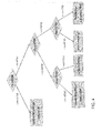
- the new metric i.e the the Mean-Time-Between-Drops MTBD may be applied to improve DLM performance on lines that are resorting to RTX as is depicted in Fig. 4 .
- QoS estimators based or not on the same or different line paremeters, may be applied for improving the line performances by means of a DLM system, for instance, in the context of RTX in the same manner as described for the Mean-Time-Between-Drops MTBD classification.
- a Dynamic Line Management system checks operations on lines without RTX enabled are as follows:
- the Mean Time Between Error MTBE is checked; in case of a low Mean Time Between Error MTBE value, the Mean Time Between Error MTBE computation should take account of coding Violations CV only. Because including the parameter Severely Errored seconds SES, EFTR drops are counted as an error event as well.
- the purpose here would be that the MTBE reflects only the transmission errors that could't be corrected (by retransmission). So the measure for improving DLM performance would be to increase the INP level (for instance by increasing the maximum delay allowed for retransmissions). However, this action is only to be taken if the MTBD is correct. Indeed, in case there are already a lot of EFTR drops because of too many retransmissions, allowing more retransmission will deteriorate the situation.
- the Dynamic Line management DLM action may be performed by any of the first controller CNTR1, second controller CNTR2 or the third controller CNTR3.
- this process assumes that the MTBE only considers CV (not ES and SES). Also, the drops included in the MTBD computation may only be taken into account if their amplitude is larger than a predefined threshold.
- This method also assumes that, like most DLM systems, this decision tree is applied every day, and all configurations that have already been tried are kept in a memory, I order to avoid trying twice a configuration that doesn't work. Otherwise, the process may not converge.
Landscapes
- Engineering & Computer Science (AREA)
- Computer Networks & Wireless Communication (AREA)
- Signal Processing (AREA)
- Environmental & Geological Engineering (AREA)
- Telephonic Communication Services (AREA)
- Data Exchanges In Wide-Area Networks (AREA)
- Detection And Prevention Of Errors In Transmission (AREA)
Priority Applications (1)
| Application Number | Priority Date | Filing Date | Title |
|---|---|---|---|
| EP14306855.9A EP3024176A1 (de) | 2014-11-21 | 2014-11-21 | Verfahren zur Beurteilung der Dienstqualität einer Datenkommunikation über eine Datenkommunikationsleitung, zugehöriges System und Vorrichtungen |
Applications Claiming Priority (1)
| Application Number | Priority Date | Filing Date | Title |
|---|---|---|---|
| EP14306855.9A EP3024176A1 (de) | 2014-11-21 | 2014-11-21 | Verfahren zur Beurteilung der Dienstqualität einer Datenkommunikation über eine Datenkommunikationsleitung, zugehöriges System und Vorrichtungen |
Publications (1)
| Publication Number | Publication Date |
|---|---|
| EP3024176A1 true EP3024176A1 (de) | 2016-05-25 |
Family
ID=52023414
Family Applications (1)
| Application Number | Title | Priority Date | Filing Date |
|---|---|---|---|
| EP14306855.9A Withdrawn EP3024176A1 (de) | 2014-11-21 | 2014-11-21 | Verfahren zur Beurteilung der Dienstqualität einer Datenkommunikation über eine Datenkommunikationsleitung, zugehöriges System und Vorrichtungen |
Country Status (1)
| Country | Link |
|---|---|
| EP (1) | EP3024176A1 (de) |
Cited By (5)
| Publication number | Priority date | Publication date | Assignee | Title |
|---|---|---|---|---|
| CN106339043A (zh) * | 2016-08-26 | 2017-01-18 | 天津市英贝特航天科技有限公司 | 一种基于vpx和cpex总线的多功能背板 |
| US10103997B2 (en) | 2016-06-01 | 2018-10-16 | At&T Intellectual Property I, L.P. | Dynamic quality of service for over-the-top content |
| EP3399694A1 (de) | 2017-05-02 | 2018-11-07 | Nokia Solutions and Networks Oy | Verfahren und vorrichtung zur beurteilung einer dienstqualität (qos) von datenkommunikationssystemen |
| US11029592B2 (en) | 2018-11-20 | 2021-06-08 | Flightsafety International Inc. | Rear projection simulator with freeform fold mirror |
| US11122243B2 (en) | 2018-11-19 | 2021-09-14 | Flightsafety International Inc. | Method and apparatus for remapping pixel locations |
Citations (1)
| Publication number | Priority date | Publication date | Assignee | Title |
|---|---|---|---|---|
| US20070124727A1 (en) * | 2005-10-26 | 2007-05-31 | Bellsouth Intellectual Property Corporation | Methods, systems, and computer programs for optimizing network performance |
-
2014
- 2014-11-21 EP EP14306855.9A patent/EP3024176A1/de not_active Withdrawn
Patent Citations (1)
| Publication number | Priority date | Publication date | Assignee | Title |
|---|---|---|---|---|
| US20070124727A1 (en) * | 2005-10-26 | 2007-05-31 | Bellsouth Intellectual Property Corporation | Methods, systems, and computer programs for optimizing network performance |
Non-Patent Citations (2)
| Title |
|---|
| "ITU-T Improved impulse noise protection for DSL transceivers", 21 April 2011 (2011-04-21), pages 1 - 78, XP055175260, Retrieved from the Internet <URL:https://www.itu.int/rec/T-REC-G.998.4-201006-S/en> [retrieved on 20150310] * |
| "TR-197- DQS: DSL Quality Management Techniques and Nomenclature", 22 August 2012 (2012-08-22), pages 1 - 61, XP055175052, Retrieved from the Internet <URL:http://www.broadband-forum.org/technical/download/TR-197.pdf> [retrieved on 20150310] * |
Cited By (10)
| Publication number | Priority date | Publication date | Assignee | Title |
|---|---|---|---|---|
| US10103997B2 (en) | 2016-06-01 | 2018-10-16 | At&T Intellectual Property I, L.P. | Dynamic quality of service for over-the-top content |
| US11190453B2 (en) | 2016-06-01 | 2021-11-30 | At&T Intellectual Property I, L.P. | Dynamic quality of service for over-the-top content |
| CN106339043A (zh) * | 2016-08-26 | 2017-01-18 | 天津市英贝特航天科技有限公司 | 一种基于vpx和cpex总线的多功能背板 |
| EP3399694A1 (de) | 2017-05-02 | 2018-11-07 | Nokia Solutions and Networks Oy | Verfahren und vorrichtung zur beurteilung einer dienstqualität (qos) von datenkommunikationssystemen |
| US11122243B2 (en) | 2018-11-19 | 2021-09-14 | Flightsafety International Inc. | Method and apparatus for remapping pixel locations |
| US11595626B2 (en) | 2018-11-19 | 2023-02-28 | Flightsafety International Inc. | Method and apparatus for remapping pixel locations |
| US11812202B2 (en) | 2018-11-19 | 2023-11-07 | Flightsafety International Inc. | Method and apparatus for remapping pixel locations |
| US12192686B2 (en) | 2018-11-19 | 2025-01-07 | Flightsafety International Inc. | Method and apparatus for remapping pixel locations |
| US11029592B2 (en) | 2018-11-20 | 2021-06-08 | Flightsafety International Inc. | Rear projection simulator with freeform fold mirror |
| US11709418B2 (en) | 2018-11-20 | 2023-07-25 | Flightsafety International Inc. | Rear projection simulator with freeform fold mirror |
Similar Documents
| Publication | Publication Date | Title |
|---|---|---|
| EP2055086B1 (de) | Verfahren und vorrichtung zur analyse und unterdrückung der geräusche in einer digitalen teilnehmerleitung | |
| EP2806594B1 (de) | Verfahren und vorrichtung zur bewertung der stabilität einer telekommunikationsleitung | |
| US8005007B2 (en) | Method, adjusting apparatus and system for improving line stability | |
| CN101517965B (zh) | 视频流诊断 | |
| CN103957144B (zh) | 对网络连接的监视 | |
| US8537683B2 (en) | Method for estimating the quality of experience of a user in respect of audio and/or video contents distributed through telecommunications networks | |
| US8462648B2 (en) | Data communication | |
| EP3024176A1 (de) | Verfahren zur Beurteilung der Dienstqualität einer Datenkommunikation über eine Datenkommunikationsleitung, zugehöriges System und Vorrichtungen | |
| CN106134130A (zh) | 用于实时视频流量的动态有效速率估计的系统和方法 | |
| Muntean et al. | Objective and subjective evaluation of QOAS video streaming over broadband networks | |
| EP2005648B1 (de) | Anordnung und verfahren zum konfigurieren von digitalen teilnehmeranschlüssen | |
| CN111162877A (zh) | 一种音视频服务质量控制的自适应前向纠错方法及应用 | |
| US9042251B2 (en) | Parameter prediction for autonomous DSL system configuration profile selection | |
| US10200238B2 (en) | Dynamic line management | |
| US8159942B2 (en) | Method of selecting a profile of a broadband communication line | |
| EP3091724A1 (de) | Verfahren und vorrichtung zur bestimmung der stabilität einer digitalen teilnehmerleitung | |
| US8068584B2 (en) | System and method for selecting a profile for a digital subscriber line | |
| EP3493443B1 (de) | Verfahren und vorrichtung zum dynamischen konfigurieren von fec oder arq als impulsgeräuschschutz auf einer kommunikationsleitung | |
| EP3163784A1 (de) | Verfahren und vorrichtung zur steuerung einer digitalen teilnehmerleitung | |
| WO2017193649A1 (zh) | 数字用户线路的优化方法及装置 | |
| Mondal et al. | SureCall: Towards glitch-free real-time audio/video conferencing |
Legal Events
| Date | Code | Title | Description |
|---|---|---|---|
| AK | Designated contracting states |
Kind code of ref document: A1 Designated state(s): AL AT BE BG CH CY CZ DE DK EE ES FI FR GB GR HR HU IE IS IT LI LT LU LV MC MK MT NL NO PL PT RO RS SE SI SK SM TR |
|
| AX | Request for extension of the european patent |
Extension state: BA ME |
|
| PUAI | Public reference made under article 153(3) epc to a published international application that has entered the european phase |
Free format text: ORIGINAL CODE: 0009012 |
|
| 17P | Request for examination filed |
Effective date: 20161125 |
|
| RBV | Designated contracting states (corrected) |
Designated state(s): AL AT BE BG CH CY CZ DE DK EE ES FI FR GB GR HR HU IE IS IT LI LT LU LV MC MK MT NL NO PL PT RO RS SE SI SK SM TR |
|
| 17Q | First examination report despatched |
Effective date: 20170116 |
|
| RAP1 | Party data changed (applicant data changed or rights of an application transferred) |
Owner name: ALCATEL LUCENT |
|
| STAA | Information on the status of an ep patent application or granted ep patent |
Free format text: STATUS: THE APPLICATION IS DEEMED TO BE WITHDRAWN |
|
| 18D | Application deemed to be withdrawn |
Effective date: 20180103 |