EP3884142B1 - Separatorteller für einen ölnebelabscheider und ölnebelabscheider - Google Patents
Separatorteller für einen ölnebelabscheider und ölnebelabscheider Download PDFInfo
- Publication number
- EP3884142B1 EP3884142B1 EP20737398.6A EP20737398A EP3884142B1 EP 3884142 B1 EP3884142 B1 EP 3884142B1 EP 20737398 A EP20737398 A EP 20737398A EP 3884142 B1 EP3884142 B1 EP 3884142B1
- Authority
- EP
- European Patent Office
- Prior art keywords
- separator
- separator plate
- web
- ring
- webs
- Prior art date
- Legal status (The legal status is an assumption and is not a legal conclusion. Google has not performed a legal analysis and makes no representation as to the accuracy of the status listed.)
- Active
Links
Images




Classifications
-
- F—MECHANICAL ENGINEERING; LIGHTING; HEATING; WEAPONS; BLASTING
- F01—MACHINES OR ENGINES IN GENERAL; ENGINE PLANTS IN GENERAL; STEAM ENGINES
- F01M—LUBRICATING OF MACHINES OR ENGINES IN GENERAL; LUBRICATING INTERNAL COMBUSTION ENGINES; CRANKCASE VENTILATING
- F01M13/00—Crankcase ventilating or breathing
- F01M13/04—Crankcase ventilating or breathing having means for purifying air before leaving crankcase, e.g. removing oil
-
- B—PERFORMING OPERATIONS; TRANSPORTING
- B01—PHYSICAL OR CHEMICAL PROCESSES OR APPARATUS IN GENERAL
- B01D—SEPARATION
- B01D45/00—Separating dispersed particles from gases or vapours by gravity, inertia, or centrifugal forces
- B01D45/12—Separating dispersed particles from gases or vapours by gravity, inertia, or centrifugal forces by centrifugal forces
- B01D45/14—Separating dispersed particles from gases or vapours by gravity, inertia, or centrifugal forces by centrifugal forces generated by rotating vanes, discs, drums or brushes
-
- F—MECHANICAL ENGINEERING; LIGHTING; HEATING; WEAPONS; BLASTING
- F01—MACHINES OR ENGINES IN GENERAL; ENGINE PLANTS IN GENERAL; STEAM ENGINES
- F01M—LUBRICATING OF MACHINES OR ENGINES IN GENERAL; LUBRICATING INTERNAL COMBUSTION ENGINES; CRANKCASE VENTILATING
- F01M13/00—Crankcase ventilating or breathing
- F01M13/04—Crankcase ventilating or breathing having means for purifying air before leaving crankcase, e.g. removing oil
- F01M2013/0422—Separating oil and gas with a centrifuge device
Definitions
- the invention relates to a separator plate for an oil mist separator, in particular for separating oil from crankcase gases, according to the preamble of claim 1, and to an oil mist separator with at least one such separator plate.
- blow-by gases During the combustion process in piston engines, a small proportion of the exhaust gases flow past the side of the piston or pistons and thus from the combustion chamber into the crankshaft housing. These exhaust gases flowing past the piston are referred to as blow-by gases. Blow-by gases must be removed from the crankcase because they reduce the differential pressure between the combustion chamber and the crankcase and thus the efficiency of the engine. Quite apart from that, crankcases are usually not designed for these higher pressures.
- crankshaft housings usually have an outlet for these blow-by gases.
- these exhaust gases have a significant oil mist content that must not be released into the environment. Therefore, among other things, in the US 6,755,896B proposed an oil mist separator working according to the centrifuge principle.
- This has a housing with a gas inlet, a gas outlet and an oil outlet.
- the blow-by gases meet rapidly rotating conical separator plates, which rotate with a shaft at an axial distance from one another. Oil droplets accumulate on the rotating separator plates and are then flung against the housing wall. The oil flows along the housing wall to a collecting channel, which ends in the oil outlet.
- the blow-by gases cleaned in this way leave the housing via the gas outlet.
- the separator plates may be plastic.
- For a similarly constructed other oil mist separator is in the WO 2012/033440 A proposed to manufacture separator plates from sheet metal.
- the EP 3 034 821 A1 describes an oil mist separator that is placed in a flow channel. Oil mist enters the oil mist separator through openings, where the oil mist is accelerated. The accelerated oil mist hits an absorbent baffle plate in the oil mist separator, where the oil is separated from the gas. The cleaned gas flows around the baffle plate and exits the oil mist separator through a central opening in the baffle plate or on the side of the baffle plate.
- the invention is based on the observation that oil mist separators on the one hand reduce the environmental pollution of piston engines through oil mist ren, but at the same time increase the total weight of the engine, which is reflected in increased material costs and the use of piston engines to drive motor vehicles fuel consumption and thus the CO 2 balance deteriorated.
- the object of the invention is to reduce the costs for piston engines and at the same time to improve the CO2 balance of the production and operation of piston engines.
- the separator plate according to the invention serves in particular to separate oil mist, other liquids or particles from blow-by gases or, more generally, from gas-fluid mixtures.
- the separator plate has a mount for a drive shaft, so that the drive shaft and the separator plate have a common axis of rotation in the assembled state.
- the separator plate is disk-shaped and can therefore also be referred to as a separator disk or separator plate, with the separator disk or plate preferably not being flat but having at least one conical surface, so that the term separator plate is more descriptive based on the shape of a simple soup plate.
- the separator disc has a first ring area, which adjoins the receptacle radially.
- the inner edge i.e. the edge of the first ring area pointing in the direction of the axis of rotation, is preferably designed as a rotating coupling.
- the contour of the rim can be discontinuously rotationally symmetrical, so that a rotational movement-transmitting form fit with a drive shaft is made possible. This simplifies the assembly of the separator plate on a drive shaft of an oil mist separator.
- a second ring area adjoins the first ring area in the radial direction. And this second ring area is followed by a third ring area, also in the radial direction.
- the radial direction designates the direction pointing away from the axis of rotation.
- the third ring area preferably extends conically at least in one section.
- Conical preferably but not necessarily means corresponding to the surface of a cone, ie a truncated cone.
- the term "conical surface” is to be understood geometrically here, ie a conical surface is formed by rotating a curve about a straight line, here about the axis of rotation. The curve can also be a straight line segment, which results in the above-mentioned cone surface which is also called the truncated cone surface (cf. Bronstein Semendjajev, Handbuch dermathetician, Ch. 3.1.2.4, Verlag Harry Deutsch Frankfurt/Main, 1993 ).
- the second ring portion preferably has a plurality of spokes interconnecting the first and third ring portions. Between each two adjacent spokes there is preferably a free space which, during operation, serves as a flow channel extending in the axial direction for the gas mixture to be separated.
- the separator plate can be manufactured as an injection molded part with a particularly thin wall thickness of the third section by a favorable choice of the sprue points compared to the prior art, which means that less material is required and the manufacturing process is accelerated. In addition, the separator plate accelerates faster, so that the oil mist is safely separated even during the start-up phase of the piston engine. The environmental impact is reduced accordingly. Another effect is the contribution to reducing the weight of modern piston engines, which leads to CO 2 savings when used as a motor vehicle drive.
- the separator plate is preferably an injection molded part, ie it is produced in an injection molding process, preferably from a plastic.
- the separator plate preferably has at least two gate points, which can be arranged symmetrically around the axis of rotation, for example. The lowest possible number of sprue points reduces the production costs.
- the symmetrical arrangement makes it possible to reduce the material thickness, ie the wall thickness in particular of the third ring section.
- the symmetrical arrangement counteracts the formation of weld lines that occur when flow fronts meet in the injection molding process.
- a single gate may suffice.
- the at least one sprue point is preferably in the first or in the second ring area, for example at least one sprue point can be arranged in the area of a spoke.
- the sprue point is the opening in the injection mold through which a plastic compound that solidifies later, usually a plastic melt, is pressed into the injection mold.
- plastic melt is used as the most common form of application, but a plastic mass that later hardens through chemical processes could also be used.
- plastic melt is mentioned as a preferred embodiment in this application and is understood as pars-pro-toto for a flowable plastic mass that later solidifies (e.g., hardens).
- thermoplastics with a cfw. suitable for a high degree of polymerization such as polyamides (PA66, PA6.10,...), and in particular partially aromatic polyamides, ie polyamides with an aromatic system adjacent to the polyamide bond, such as polyphthalamide (PPA) and polyamides with aliphatic hydrocarbon chains (PA4T, PA6T, PA9T, PA10T,...), as well as copolymers with such plastics (PA6T/6I, PA6T/66, PA6T/DT, PA6T/6I/66, PA66+PA6I/6T, PA6/PA6T,).
- PPA polyphthalamide
- PA6T/6I, PA6T/66, PA6T/DT, PA6T/6I/66, PA66+PA6I/6T, PA6/PA6T PA6/PA6T
- these tend to have poor flow properties because the melt viscosity is high due to the complex chemical structure. This often leads to weld lines, which impair mechanical stability and require
- the degree of polymerization also indicates the number of basic building blocks per polymer molecule in accordance with the usual definition.
- the average degree of polymerization is relevant for the thermoplastics mentioned above.
- this should preferably be greater than or equal to 100, particularly preferably greater than or equal to 120, or particularly preferably greater than or equal to 150. Since the flow behavior in the injection molding process deteriorates with an increasing degree of polymerization, excessive degrees of polymerization, for example degrees of polymerization greater than 200 or at least greater than 250, should be avoided when polyamides are used.
- the complementary projections of the injection mold are effective as a throttle for the flow channel formed by the injection mold, which becomes visible as a spoke in the demolded state.
- This throttle makes it possible to simulate the flow resistance that the plastic melt has to overcome during injection molding in order to flow into the third area via a spoke that is further away from the sprue point (hence what is referred to below as a spoke that is far from the sprue ).
- the plastic melt is distributed more evenly over the first ring area (more precisely over the cavity of the injection mold that defines the ring area) over all spokes, ie also over spokes further away from the gate.
- the pressure of the plastic melt at the end of the flow channels, which later become visible as spokes close to the sprue, is at least approximately adapted to the pressure at the radial end of the flow ducts, which define spokes far from the sprue. Since the spokes (more precisely, the complementary channels of the injection mold) form the inflow to the third ring section, the flow front therefore forms at least largely uniformly in the radial direction to the outside.
- the stability of the separator plate is therefore not reduced or only minimally reduced by weld lines.
- the wall thickness can be further reduced accordingly.
- a spoke is close to a sprue if it either has a sprue or is located closer to a sprue than a spoke far from the sprue.
- the cross-sectional area extends transversely to the longitudinal direction of the respective spoke and that the sprue point(s) is (are) arranged radially on the inside of the tapered section of the spoke(s) near the sprue.
- spokes are of the same length, but this is not necessarily the case.
- the flow resistance of the spokes can be adjusted not only via the cross section, but alternatively or additionally via their length.
- spokes far from the sprue can be shorter than spokes near the sprue in order to adapt the pressure conditions at the end of the spokes to one another.
- spokes close to the sprue can run radially and those far from the sprue can run curved or at an angle to the radial.
- the corresponding injection mold has a recess which reduces the flow resistance in the radial direction.
- the webs increase the friction between the rotating separator plate and the gas-liquid mixture to be separated, e.g. a blow-by gas, which is only an example for all gas-liquid mixtures within the scope of this application.
- the gas mixture is rotated better, so that fewer separator plates are required, which in turn contributes to savings in manufacturing costs and weight. This works particularly well if the webs serve as spacers between adjacent separator plates, i.e.
- the underside of an upper separator plate rests on at least two (preferably three or more) webs, with the webs being formed on the upper side of a lower separator plate.
- the webs could of course also be formed on the underside of the upper separator plate.
- the webs can be problematic with regard to the formation of weld lines, because the plastic melt in the webs runs ahead of the rest of the flow front.
- the height h of the webs by which the webs protrude beyond the wall between two webs, is chosen to be as low as possible.
- the thickness of the separator plate in the web preferably corresponds to at least approximately twice the thickness d of the wall thickness between the webs.
- the height h of the webs is therefore the additional wall thickness with which the respective webs protrude beyond the area of the separator plate located between the webs.
- the advance of the flow front is effectively contained by the aforementioned relationships between the web height h and the thickness d of the wall lying between the webs.
- the preferred bridge height h is less than or equal to 0.3 mm (h ⁇ 0.3 mm), particularly preferably less than or equal to 0.25 mm (h ⁇ 0.25 mm) or less than or equal to 0.2 mm (h ⁇ 0.2 mm).
- the sensible lower limit depends, among other things, on the viscosity of the liquid to be separated. For current engine oils, a lower limit of 0.1mm or even 0.05mm seems to be given. If a significant number of particles is to be expected in the mixture to be separated, the expected maximum particle diameter can be a sensible lower limit. This makes it possible for the particles to pass through the gap at least essentially unhindered.
- the web height determines the height of the resulting gap when using the webs as spacers between the plates, lower web heights lead to a reduction in the height of the entire stack of plates and thus to a reduction in installation space. It has also been found that a small gap height has a particularly advantageous effect on the separation of the finest oil droplets, i.e. the separation of the finest oil droplets is favored over a larger gap.
- At least two adjacent spokes are each connected at least indirectly to a web in the radial direction, with at least one radially extending intermediate web being located between the two webs.
- the intermediate web also makes it possible to fill the area between the webs particularly evenly during injection molding.
- the critical weld lines are further reduced and the wall thickness can be reduced accordingly.
- the spokes, or at least some spokes, open into a ring or one or more ring segments, which have an increased wall thickness compared to the radially outer area of the third section.
- the corresponding annular cavity of the injection mold allows in this way Particularly even filling of the radially outer annular gap of the injection mold.
- the ring or the at least one ring segment can be connected to one or more intermediate webs.
- the corresponding annular cavity of the injection mold then feeds the recess for the gutters, i.e. the viscosity-related pressure drop of the flowing plastic on the way to the corresponding "gutter" (meaning the recess surrounding the gutter) is reduced and the recesses are evenly filled with plastic. All this in turn serves to avoid weld lines, which enables a further reduction in wall thickness and thus cost and weight savings.
- the cross-sectional areas of the at least one web and/or the at least one intermediate web preferably taper in the radial direction.
- the cross-sectional area A z (r) of the at least one intermediate web as a function of the radius is preferably greater than at least one of the respective cross-sectional areas As(r) of the two webs including the intermediate web at the given radius, i.e. A z (r)> As(r) , preferably A z (r) ⁇ 1.2 * A S (r), particularly preferably A z (r) ⁇ 1.5 * A S (r) or A z (r) ⁇ 2 * A S (r).
- the quality of the separator plate is further increased, ie weld lines are further reduced.
- the radius denotes the distance from the axis of rotation.
- At least one web has a cross-sectional area that first decreases in the radial direction and then increases again.
- the complementary projection of the injection mold reduces the flow of plastic into the recess that later forms the web, ie it acts as a throttle and increases the portion of the flow in the circumferential direction, eg in the direction of an intermediate web recess flowing plastic, the weld lines are further reduced. If a plurality of intermediate webs are arranged between two adjacent webs, the intermediate webs close to the web can also have a cross-sectional area which first decreases in the radial direction and then increases again.
- the third section preferably consists at least essentially of a conical ring segment, with an at least largely constant wall thickness with the exception of the optional webs and optional intermediate webs as well as the optional ring described above for distributing the plastic in the circumferential direction.
- the wall thickness of the third ring section between two adjacent webs and/or between one web and an adjacent intermediate web is constant up to 10% in the circumferential direction and/or in the radial direction.
- the preferred average wall thickness d m is less than or equal to 0.3 mm (d m ⁇ 0.3 mm), particularly preferably less than or equal to 0.25 mm (d m ⁇ 0.25 mm) or less than or equal to 0.2 mm (d m ⁇ 0.2 mm ).
- a surface texturing can be provided on the surface, e.g. in the form of micro-indentations or elevations. Such texturing can be achieved particularly well with the preferred small wall thicknesses, since an advantageous rapid cooling of the surface layer is achieved with these.
- the separator plate described is preferably used in an oil mist separator, for example for blow-by gases from piston engines, but the principle described is not limited to this application of the invention.
- the separator plate described can also be used in other technical areas in which gas-liquid phases are separated.
- the respective separator has a housing having at least one gas inlet, at least one gas outlet and at least one oil outlet. Sitting in the housing then at least one separator plate on a rotary driven shaft. A plurality of separator plates preferably sit one above the other on the shaft.
- At least two separator plates are seated in the housing on the rotationally driven shaft.
- the at least two separator plates are preferably arranged one above the other (i.e. stacked in the axial direction).
- a gap can be formed between the at least two separator plates in the first ring area.
- the thickness of the stack formed by the two adjacent separator plates i.e. the sum of the thicknesses of the respective separator plates (including the gap formed between them) is preferably less than or equal to 1 mm, preferably less than or equal to 0.8 mm, particularly preferably less than or equal to 0.6 mm .
- the thickness is only limited by the strength of the material of the separator plates and the viscosity of the oil to be separated. 0.25 mm can currently be regarded as a reasonable lower limit for the thickness of the package.
- the gap formed in the first ring area between the two separator plates preferably has a height of less than or equal to 0.3 mm, particularly preferably less than or equal to 0.2 mm.
- a gap of around 0.05 mm is assumed to be the lower gap limit for oil mist separators. However, this lower limit depends on the viscosity of the oil to be separated. The thinner the fluid to be separated, the smaller the gap can be. If the mixture to be separated also contains particles, e.g. soot or the like, the gap thickness should preferably not be smaller than the expected particle diameter.
- FIG. 1 shows a top view of a separator plate 1.
- the separator plate 1 has three ring-shaped areas.
- the first ring area 10 is delimited radially inward by a receptacle 3 for a shaft.
- the common axis of rotation of the shaft and the separator plate 1 runs orthogonally to the plane of the drawing and is identified by the reference number 2 .
- the first ring area 10 then merges radially outwards into a second ring area 20, which is essentially formed from preferably evenly arranged spokes 21 and the openings 22 located between them.
- the spokes 21 end at a ring 35 on the inner edge of the third ring area 30.
- the third ring area 30 extends to the edge 99 of the separator plate 1, which closes it off radially to the outside.
- the boundaries between the ring areas 10, 20, 30 are drawn in as dashed lines.
- the respectively adjacent annular regions 10 and 20 as well as 20 and 30 consequently border one another, preferably without a transition.
- the radial expansion of the ring areas is represented by double arrows.
- the third ring area has a conical section 31 adjoining the ring 35, with the axis of rotation 2 as the cone axis (cf. 2 and 3 ).
- the recording 3 for the shaft is a central through hole.
- the contour of the through-hole 3 preferably has a discontinuous rotational symmetry, so that no imbalance occurs but a torque-transmitting form fit of the separator plate 1 with a complementary shaft is made possible.
- Other options for torque transmission such as a frictional connection between the shaft and/or separator plates 1 stacked on top of one another, are also possible.
- the example shown has a plurality of webs 40 on its upper side, which are preferably arranged in the plan view in the radial extension of a spoke 21 in each case.
- at least one intermediate web 50 is arranged between each two webs 40 .
- the webs 40 and the intermediate webs 50 are elevations in the upper side of the third annular region 30, which otherwise preferably has at least essentially the surface of a cone segment, e.g. that of a truncated cone.
- the webs 40 and the intermediate webs 50 serve as spacers which rest on the underside of a separator plate 1 stacked on the shaft above the separator plate 1 shown.
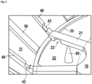
- figure 2 shows a detail of the separator plate 1 in a perspective view, specifically a section of the second ring area 20 with sections of the adjoining first and third ring area 10 or 30.
- an injection nozzle 80 of an injection mold is sketched as a truncated cone (see Fig . also Fig.3 ).
- the flattened tip of the truncated cone thus defines a gate location.
- the flattened tip attaches to the underside of the separator plate 1, more precisely to a spoke 21 (ie in the second area 20).
- the spoke 21 is therefore a spoke 21 close to the sprue.
- the spoke 21 near the gate has a region 23 with a tapered cross-sectional area. In production, this area is realized by a projection of the injection mold.
- the plastic melt can therefore not only flow radially outwards from the sprue point via the spoke 21 close to the sprue, but must flow outwards via the first region 10 (i.e. the corresponding cavity of the injection mold) via other spokes 21 (i.e. also via the spokes 21 remote from the sprue).
- the flow front is evened out during the injection molding of the third ring area 30, so that it can be manufactured with a reduced wall thickness.
- the ring 35 is attached radially outwards to the spokes 21 . According to the above classification, the ring 35 is part of the third ring area 30.
- the ring 35 has a greater material thickness in comparison to the flat parts of the third ring area 30, corresponding to the corresponding ring channel of the injection mold has a larger free cross section.
- the plastic melt can therefore be distributed evenly in the circumferential direction before it enters the annular gap to form the conical, flat section 31 of the third annular region 30 .
- the injection mold In the area of the webs 40, the injection mold has a radial channel which counteracts a uniform spread of the plastic melt because the plastic melt would spread more quickly in this channel.
- at least part of the plastic melt shoots into the webs 40 located in the radial extension of the spokes 21 (more precisely, the corresponding recess).
- An optional narrowing of the cross section 43 of the webs 40 at their end region on the inlet side can counteract an uneven spread of the plastic melt during injection molding.
- the first quarter, preferably the first fifth, better still the first eighth or first tenth of the corresponding web 40 is referred to as the end region on the inlet side with respect to the axis of rotation 2 .
- the optional intermediate webs 50 also contribute to smoothing out the spread of the plastic melt, since the injection mold forms a channel with an enlarged cross section at the corresponding point. This channel is exactly in the area that is furthest away from the webs 40 (cf. Figures 1 to 3 ) and thus prevents a weld line that would otherwise be expected there. In the figures 2 and 3 It can be clearly seen that the intermediate webs 50 are shown wider than the webs 40 in order to compensate for the pressure drop in the injection mold through a larger flow cross section.
- the height h (thickness) of the webs 40 and preferably also of the intermediate webs 50 is preferably at least approximately the same ( ⁇ 10%) and is at least approximately the same ( ⁇ 10%) constant over the distance from the axis of rotation 2 (with the exception of the cross-sectionally tapered regions 43). .
- the statement "( ⁇ 10%)” is intended to make it clear that "at least approximately the same” means the same as well as deviations from the mean of up to 10% of the mean. Smaller deviations of up to ⁇ 5%, up to ⁇ 2.5% or down to 1% are increasingly preferred with decreasing size.
- the cross-sectional area of the webs 40 and/or that of the intermediate webs 50 tapers in the radial direction in order to reduce the pressure drop in the radial direction in the channels that later form the webs 40 or intermediate webs, see above that a flow front that is as uniform as possible over the circumference is generated. As a result, the separator plate is less prone to weld lines.
- figure 4 shows a cross-section taken along a circular cylinder surface around the axis of rotation in the third ring region, the viewing direction pointing radially outwards.
- the thickening of the radially outwardly tapering webs with the height h on the conically outwardly rising surface 31 with a wall thickness d can be clearly seen.
- the web height h defines the distance between two adjacent separator plates.
- figure 5 shows a sequence of images of a simulation of the spread of a plastic melt during the production of the Figures 1 to 3 illustrated separator plate.
- the flow front of the plastic mass spreads out almost rotationally symmetrically in a very short time.
- the tendency to form weld lines is therefore very low. Accordingly, the wall thickness d in the areas 31 can be particularly small.
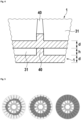
- the 6 shows an alternative for the formation of spacers on separator plates 1; the view corresponds to that in 4 .
- shafts 60 in the third ring area 30 serve as spacers, which requires that adjacent separator plates 1 are stacked on the shaft, rotated relative to one another, as indicated.
- the corrugations 60 form beads 60 with a height have the advantage over the webs 40 that the corresponding injection mold has no areas in which the gap thickness increases (significantly).
- the cross-sectional tapers 43 described above with reference to the webs 40 can therefore be less pronounced on the input side of the beads 60 or can even be omitted entirely.
- the wall thickness d of the separator plates 1 remains essentially ( ⁇ 10%) constant over the entire circumference, ie the wall thickness of the bead 60 is the same as in the area between the beads 60.
- the beads 60 are otherwise like those described above Webs 40 and/or intermediate webs 50 are arranged, ie they preferably extend at least approximately radially, with deviations of ⁇ 30° from the respective radial being permissible.
Landscapes
- Engineering & Computer Science (AREA)
- Mechanical Engineering (AREA)
- General Engineering & Computer Science (AREA)
- Chemical & Material Sciences (AREA)
- Chemical Kinetics & Catalysis (AREA)
- Moulds For Moulding Plastics Or The Like (AREA)
- Centrifugal Separators (AREA)
Description
- Die Erfindung betrifft einen Separatorteller für einen Ölnebelabscheider insbesondere zur Abscheidung von Öl aus Kurbelgehäusegasen nach dem Oberbegriff des Anspruchs 1, sowie einen Ölnebelabscheider mit wenigstens einem solchen Separatorteller.
- Beim Verbrennungsprozess in Kolbenmotoren strömt ein geringer Teil der Abgase an dem oder den Kolben seitlich vorbei und somit vom Verbrennungsraum in das Kurbelwellengehäuse. Diese am Kolben vorbeiströmenden Abgase werden als Blow-by-Gase bezeichnet. Blow-by-Gase müssen aus dem Kurbelwellengehäuse entfernt werden, da sie den Differenzdruck zwischen Brennraum und Kurbelwellengehäuse reduzieren und damit den Wirkungsgrad des Motors. Davon ganz abgesehen, sind Kurbelwellengehäuse in der Regel für diese höheren Drücke nicht ausgelegt.
- Entsprechend haben Kurbelwellengehäuse in der Regel einen Auslass für diese Blow-by Gase. Allerdings haben diese Abgase einen nennenswerten Ölnebelanteil, der nicht in die Umgebung abgegeben werden darf. Daher wurde unter anderem in der
US 6,755,896 B ein nach dem Zentrifugenprinzip arbeitender Ölnebelabscheider vorgeschlagen. Dieser hat ein Gehäuse mit einem Gaseinlass, einem Gasauslass und einem Ölauslass. Die Blow-by-Gase treffen in dem Gehäuse auf schnell rotierende konische Separatorteller, die axial beabstandet voneinander mit einer Welle rotieren. Öltröpfchen lagern sich an den rotierenden Separatortellern an und werden anschließend an die Gehäusewand geschleudert. An der Gehäusewand entlang fließt das Öl zu einer Auffangrinne, die in dem Ölauslass mündet. Die so gereinigten Blow-by-Gase verlassen das Gehäuse über den Gasauslass. Nach derUS 6,755,896 B (hierin durch Referenz aufgenommen) können die Separatorteller aus Kunststoff sein. Für einen ähnlich aufgebauten anderen Ölnebelabscheider wird in derWO 2012/033440 A vorgeschlagen Separatorteller aus Metallblech zu fertigen. - Gegenstand der
DE 10 2017 108 168 A (hierin durch Referenz aufgenommen) ist ein Ölnebelabscheider mit einem Rotor aus mehreren gestapelten Abscheidelementen. Die Abscheideelemente haben radial an einen Ring angesetzte Speichen, mit je einer Längsachse. Die Längsachsen der Speichen befinden sich in einer gemeinsamen Ebene. In diesem Sinne ist das Abscheideelement plan. Zwischen den Speichen sind ringsegmentförmige Lamellen, die radial voneinander beabstandet sind. - Auch die
EP 3 034 821 A1 beschreibt einen Ölnebelabscheider, der in einem Strömungskanal angeordnet wird. Ölnebel tritt durch Öffnungen in den Ölnebelabscheider ein, dabei wird der Ölnebel beschleunigt. Der beschleunigte Ölnebel trifft in dem Ölnebelabscheider auf eine saugfähige Prallplatte, an der das Öl von dem Gas getrennt wird. Das gereinigte Gas umströmt die Prallplatte und tritt durch eine zentrale Öffnung in der Prallplatte oder seitlich an der Prallplatte aus dem Ölnebelabscheider aus. - Die Erfindung beruht auf der Beobachtung, dass Ölnebelabscheider zwar auf der einen Seite die Umweltbelastung von Kolbentriebwerken durch Ölnebel reduzie ren, aber gleichzeitig das Gesamtgewicht des Triebwerks erhöhen, was sich in erhöhten Materialkosten niederschlägt und beim Einsatz der Kolbentriebwerke zum Antrieb von Kraftfahrzeugen den Treibstoffverbrauch und somit die CO2-Bilanz verschlechtert.
- Der Erfindung liegt die Aufgabe die Kosten für Kolbentriebwerke zu reduzieren und gleichzeitig die COz-Bilanz der Herstellung und des Betriebs von Kolbentriebwerken zu verbessern.
- Diese Aufgabe wird durch eine Vorrichtung nach Anspruch 1 gelöst. Vorteilhafte Ausgestaltungen der Erfindung sind in den Unteransprüchen angegeben.
- Der Separatorteller nach der Erfindung dient insbesondere zum Abscheiden von Ölnebel, anderen Flüssigkeiten oder Partikeln von Blow-by-Gasen oder ganz allgemein von Gas-Fluid Gemischen. Der Separatorteller hat eine Aufnahme für eine Antriebswelle, so dass die Antriebswelle und der Separatorteller im montierten Zustand eine gemeinsame Rotationsachse aufweisen. Der Separatorteller ist scheibenförmig und kann daher auch als Separatorscheibe oder Separatorplatte bezeichnet werden, wobei die Separatorscheibe oder -platte vorzugsweise nicht plan ist, sondern wenigstens eine konische Oberfläche aufweist, so dass der Begriff Separatorteller in Anlehnung an die Form eines einfachen Suppentellers anschaulicher ist.
- Die Separatorscheibe hat einen ersten Ringbereich, der sich radial an die Aufnahme anschließt. Der innere Rand, d.h. der in Richtung der Rotationsachse weisende Rand des ersten Ringbereichs ist vorzugsweise als Drehkupplung ausgebildet. Beispielsweise kann die Kontur des Randes diskontinuierlich rotationssymmetrisch sein, so dass ein drehbewegungsübertragender Formschluss mit einer Antriebswelle ermöglicht wird. Dadurch wird die Montage des Separatortellers auf einer Antriebswelle eines Ölnebelabscheiders vereinfacht.
- Diskontinuierlich rotationssymmetrisch bezeichnet hier eine gebrochene Rotationssymmetrie, wobei eine Drehung der Kontur um einen festen Winkel α=360°/n (n>1) die Kontur auf sich selber abbildet.
- An den ersten Ringbereich schließt sich in radialer Richtung ein zweiter Ringbereich an. Und an diesen zweiten Ringbereich schließt sich ein dritter Ringbereich ebenfalls in radialer Richtung an. Die radiale Richtung bezeichnet hier wie üblich die von der Rotationsachse wegweisende Richtung.
- Der dritte Ringbereich erstreckt sich vorzugsweise zumindest in einem Abschnitt konisch. "Konisch" meint vorzugsweise aber nicht notwendigerweise der Fläche eines Kegelkonus, also eines Kegelstumpfs, entsprechend. Der Begriff "konische Fläche" ist hier geometrisch zu verstehen, d.h. eine Konusfläche wird durch Rotation einer Kurve um eine Gerade, hier um die Rotationsache gebildet. Die Kurve kann auch ein Geradenabschnitt sein, dann ergibt sich die schon genannte Kegelkonusfläche die auch als Kegelstumpffläche bezeichnet wird (vgl. Bronstein Semendjajev, Handbuch der Mathematik, Kap. 3.1.2.4, Verlag Harry Deutsch Frankfurt/Main, 1993).
- Der zweite Ringbereich hat vorzugsweise mehrere Speichen, die den ersten und den dritten Ringbereich miteinander verbinden. Zwischen je zwei benachbarten Speichen ist vorzugsweise je ein Freiraum, der im Betrieb als sich in axialer Richtung erstreckender Strömungskanal für das zu trennende Gasgemisch dient. Der Separatorteller lässt sich durch eine günstige Wahl der Angussstellen im Vergleich mit dem Stand der Technik als Spritzgussteil mit einer besonders dünnen Wandstärke des dritten Abschnitts fertigen, was dazu führt, dass weniger Material benötigt wird und der Fertigungsprozess beschleunigt wird. Zudem beschleunigt der Separatorteller schneller, so dass auch in der Anlassphase des Kolbenmotors der Ölnebel sicher abgeschieden wird. Die Umweltbelastung wird entsprechend verringert. Ein weiterer Effekt ist der Beitrag zur Gewichtsreduzierung moderner Kolbenmotoren, was zu CO2-Einsparung beim Einsatz als Kraftfahrzeugantrieb führt.
- Vorzugsweise ist der Separatorteller ein Spritzgussteil, d.h. er wird im Spritzgussverfahren, vorzugsweise aus einem Kunststoff hergestellt. Der Separatorteller hat vorzugsweises wenigstens zwei Angussstellen, die beispielsweise symmetrisch um die Rotationsachse angeordnet sein können. Eine möglichst geringe Anzahl von Angussstellen reduziert die Fertigungskosten. Die symmetrische Anordnung ermöglicht eine Verringerung der Materialstärke, d.h. der Wanddicke insbesondere des dritten Ringabschnitts. Die symmetrische Anordnung wirkt einer Ausbildung von Bindenähten entgegen, die durch das Aufeinandertreffen von Fließfronten im Spritzgussprozess entstehen. Eine einzige Angussstelle kann jedoch genügen.
- Vorzugsweise ist die wenigstens eine Angussstelle im ersten oder im zweiten Ringbereich, beispielsweise kann wenigstens eine Angussstelle im Bereich einer Speiche angeordnet sein.
- Als Angussstelle bezeichnet man beim Spritzgießen die Öffnungen der Spritzgussform, über die eine später erstarrende Kunststoffmasse, in der Regel eine Kunststoffschmelze, in die Spritzgussform eingepresst wird. Diese Angussstellen sind nach dem Entformen deutlich zu erkennen, zumindest wenn keine Politur oder andere flächige Materialabtragung nach dem Entformen erfolgt. Nachfolgend wird der Begriff Kunststoffschmelze als häufigste Anwendungsform verwendet, es wäre aber auch eine später durch chemische Prozesse aushärtende Kunststoffmasse verwendbar. In diesem Sinne wird in dieser Anmeldung "Kunststoffschmelze" als bevorzugte Ausführungsform genannt und als pars-pro toto für eine fließfähige später erstarrende (z.B. aushärtende) Kunststoffmasse verstanden.
- Bei der Fertigung von Separatortellern aus Kunststoff die für die Reinigung von Blow-by Gasen bestimmt sind, müssen Kunststoffe gewählt werden, die auch bei Temperaturen um 120°C eine ausreichende mechanische Festigkeit und chemische Resistenz aufweisen. Daher sind insbesondere Thermoplaste mit einem vglw. hohen Polymerisationsgrad geeignet, wie z.B. Polyamide (PA66, PA6.10,...), und insbesondere teilaromatisierte Polyamide, d.h. Polyamide mit einem aromatischen System in Nachbarstellung zur Polyamidbindung, wie Polyphtalamid (PPA) und Polyamide mit aliphatischen Kohlenwasserstoffketten (PA4T, PA6T, PA9T, PA10T,...), sowie Copolymere mit solchen Kunststoffen (PA6T/6I, PA6T/66, PA6T/DT, PA6T/6I/66, PA66+PA6I/6T, PA6/PA6T,...). Diese haben jedoch im Vergleich zu anderen Kunststoffen eher schlechte Fließeigenschaften, da aufgrund der komplexen chemischen Struktur die Schmelzviskosität hoch ist. Dies führt dann oft zu Bindenähten, die mechanische Stabilität verschlechtern und eine Erhöhung der Wandstärken erfordern.
- Nur zur Vermeidung von Missverständnissen sei klargestellt, dass der Polymerisationsgrad entsprechend der üblichen Definition auch hier die Anzahl der Grundbausteine pro Polymermolekül angibt. In der Praxis ist dann natürlich für die oben genannten Thermoplaste der mittlere Polymerisationsgrad relevant. Dieser sollte für die oben genannten Polyamide vorzugsweise größer gleich 100 sein, besonders bevorzugt größer gleich 120 oder insbesondere bevorzugt größer gleich 150 sein. Da mit zunehmendem Polymerisationsgrad das Fließverhalten im Spritzgussverfahren schlechter wird, sollten überhöhte Polymerisationsgrade, beispielsweise Polymerisationsgrade größer als 200 oder zumindest größer als 250, vermieden werden, wenn Polyamide eingesetzt werden.
- Wenn die Speichen, die den jeweiligen Angussstellen benachbart sind und/oder eine Angussstelle aufweisen, radial der Angussstelle zumindest einen Abschnitt mit einer verjüngten Querschnittsfläche aufweisen (z.B. im Vergleich zu den anderen Speichen insgesamt einen verjüngten Querschnitt aufweisen), dann wirken die komplementären Vorsprünge der Spritzgussform als Drossel für den von der Spritzgussform gebildeten Strömungskanal, der im entformten Zustand als Speiche sichtbar wird. Diese Drossel ermöglicht es den Strömungswiderstand zu simulieren, den die Kunststoffschmelze beim Spritzgießen überwinden muss, um über eine weiter von der Angussstelle entfernte Speiche (also eine nachfolgend sogenannte angussferne Speiche), in den dritten Bereich zu fließen. Daher verteilt sich die Kunststoffschmelze beim Spritzgießen über den ersten Ringbereich (genauer über den den Ringbereich definierenden Hohlraum der Spritzgussform) gleichmäßiger auf alle Speichen, also auch auf weiter von der Angussstelle entfernte Speichen. Entsprechend ist der Druck der Kunststoffschmelze am Ende der Strömungskanäle, die später als angussnahe Speichen sichtbar werden, zumindest in etwa an den Druck am radialen Ende der Strömungskanäle angepasst, die angussferne Speichen definieren. Da die Speichen (genauer die komplementären Kanäle der Spritzgussform) den Zufluss zu dem dritten Ringabschnitt bilden, bildet sich die Fließfront daher zumindest weitgehend gleichmäßig in radialer Richtung nach Außen aus. Die Stabilität des Separatortellers wird daher durch Bindenähte nicht oder nur minimal reduziert. Die Wandstärke kann entsprechend weiter reduziert werden.
- Zur sprachlichen Vereinfachung wird hierin nicht mehr zwischen einem Hohlraum der Spritzgussform und dem später darin ausgebildeten Element unterschieden. Wenn formuliert wird, dass eine Kunststoffschmelze durch eine Speiche fließt, ist damit gemeint, dass die Kunststoffschmelze durch einen Hohlraum einer Spritzgussform fließt, wobei der Hohlraum unmittelbar vor dem Entformen des Separatortellers die genannte Speiche umschließt. Entsprechendes gilt für andere Teile oder Abschnitte des Separatortellers. Hohlräume einer Spritzgußform werden vereinfachend durch die von ihnen geformten Teile, Komponenten oder Abschnitte bezeichnet.
- Angussnah ist eine Speiche, wenn sie entweder einen Anguss hat oder näher an einem Anguss angeordnet ist, als eine angussferne Speiche.
- Nur um Fehlinterpretationen vorzubeugen ist anzumerken, dass die Querschnittsfläche sich quer zur Längsrichtung der jeweiligen Speiche erstreckt und dass die Angussstelle(n) radial innenliegend des verjüngten Abschnitts der angussnahen Speiche(n) angeordnet ist(sind).
- Bisher wurde der Einfachheit halber davon ausgegangen, dass alle Speichen die gleiche Länge haben, das ist aber nicht notwendigerweise der Fall. Der Strömungswiderstand der Speichen (also der entsprechenden Spritzgusskanäle) lässt sich nicht nur über den Querschnitt, sondern alternativ oder zusätzlich über deren Länge einstellen, beispielsweise können angussferne Speichen kürzer als angussnahe Speichen sein, um die Druckverhältnisse am Ende der Speichen einander anzupassen. Beispielsweise können angussnahe Speichen radial verlaufen und die angussfernen gekrümmt oder schräg zur Radialen verlaufen.
- Wenn sich an wenigstens eine Speiche in radialer Richtung ein Steg anschließt, der als Verdickung der Wandstärke des konischen Abschnitts ausgebildet ist, dann hat die entsprechende Spritzgussform eine Ausnehmung, die den Strömungswiderstand in radialer Richtung reduziert. Im späteren Betrieb erhöhen die Stege die Reibung zwischen dem rotierenden Separatorteller und dem zu trennenden Gas-Flüssigkeitsgemisch, z.B., einem Blow-by-Gas, das im Rahmen dieser Anmeldung lediglich als Beispiel für alle Gas-Flüssigkeitsgemische steht. Das Gasgemisch wird besser in Rotation versetzt, so dass weniger Separatorteller notwendig sind, was wiederum zur Herstellungskosten- und Gewichtsersparnis beiträgt. Besonders gut gelingt das, wenn die Stege als Abstandshalter zwischen benachbarten Separatortellern dienen, d.h. im Ölnebelabscheider liegt die Unterseite eines oberen Separatortellers auf wenigstens zwei (vorzugsweise drei oder mehr) Stegen auf, wobei die Stege auf der Oberseite eines unteren Separatortellers ausgebildet sind. Alternativ oder zusätzlich könnten die Stege natürlich auch auf der Unterseite des oberen Separatortellers ausgebildet sein. Problematisch können die Stege aber mit Blick auf die Ausbildung von Bindenähten sein, weil in den Stegen die Kunststoffschmelze der übrigen Fließfront vorauseilt.
- Es hat sich als besonders vorteilhaft erwiesen, wenn daher die Höhe h der Stege mit der die Stege über die Wandung zwischen zwei Stegen hinausstehen möglichst niedrig gewählt wird. Beispielsweise kann die die Höhe der Stege h zumindest in etwa der Höhe der sonst herrschenden Wandstärke d entsprechen, d.h. h ≈ d, z.B. h = d ± 20%, vorzugsweise d = h ± 10%, besonders bevorzugt h = d ± 5%. Folglich entspricht die Dicke des Separatortellers im Steg vorzugsweise zumindest in etwa dem Doppelten der Dicke d der zwischen den Stegen liegenden Wandstärke. Die Höhe h der Stege ist daher die zusätzliche Wandstärke mit der die jeweiligen Stege über den zwischen den Stegen liegenden Bereich des Separatortellers hervorstehen. Durch die vorgenannten Beziehungen zwischen der Steghöhe h und der Dicke d der zwischen den Stegen liegenden Wand wird das Vorauseilen der Fließfront wirkungsvoll eingedämmt. Die bevorzugte Steghöhe h ist kleiner oder gleich 0,3mm (h≤0,3mm), besonders bevorzugt kleiner oder gleich 0,25mm (h≤0,25mm) oder kleiner gleich 0,2mm (h≤0,2mm). Die sinnvolle Untergrenze ist u.a. von der Viskosität der abzutrennenden Flüssigkeit abhängig. Für aktuelle Motoröle scheint eine Untergrenze von 0,1mm eventuell auch 0,05mm gegeben. Sofern eine nennenswerte Anzahl von Partikeln in dem zu trennenden Gemisch zu erwarten sind, kann der erwartete maximale Partikeldurchmesser eine sinnvolle Untergrenze sein. Dadurch wird ermöglicht, dass die Partikel den Spalt zumindest im Wesentlichen ungehindert passieren.
- Da die Steghöhe bei der Verwendung der Stege als Abstandshalter zwischen den Tellern die Höhe des sich ergebenden Spalts bestimmt, führen geringere Steghöhen zu einer Höhenreduzierung des gesamten Tellerstapels und somit zu einer Bauraumreduzierung. Es hat sich darüber hinaus herausgestellt, dass eine geringe Spalthöhe besonders vorteilhaft auf eine Abscheidung feinster Öltröpfchen auswirkt, d.h. die Abscheidung feinster Öltröpfchen gegenüber einem größeren Spalt begünstigt.
- Zusätzlich oder alternativ zu den Stegen können auch weitere Abstandshalter an den Separatortellern vorgesehen sein.
- Besonders bevorzugt schließt sich an wenigstens zwei benachbarte Speichen je ein Steg in radialer Richtung zumindest mittelbar an, wobei zwischen den beiden Stegen wenigstens ein sich radial erstreckender Zwischensteg ist. Der Zwischensteg ermöglicht auch den Bereich zwischen den Stegen besonders gleichmäßig beim Spritzgießen zu füllen. Die kritischen Bindenähte werden weiter reduziert und entsprechend kann die Wandstärke geringer ausfallen. Besonders bevorzugt münden die Speichen, oder wenigstens einige Speichen in einen Ring oder ein oder mehrere Ringsegmente, die gegenüber dem radial außenliegenden Bereich des dritten Abschnitts eine erhöhte Wanddicke aufweisen. Der entsprechende ringförmige Hohlraum der Spritzgussform ermöglicht auf diese Weise ein besonders gleichmäßiges Befüllen des radial außenliegenden Ringspalts der Spritzgussform. Insbesondere kann der Ring bzw. das wenigstens eine Ringsegment mit einem oder mehreren Zwischenstegen verbunden sein. Der entsprechende ringförmige Hohlraum der Spritzgussform speist dann die Ausnehmung für die Zwischenstege, d.h. der viskositätsbedingte Druckabfall des fließenden Kunststoffs auf dem Weg zu dem entsprechenden "Zwischensteg" (gemeint ist die den Zwischensteg umschließende Ausnehmung) wird reduziert und die Ausnehmungen werden gleichmäßig mit Kunststoff gefüllt. All dies dient wiederrum der Vermeidung von Bindenähten, welches eine weitere Reduktion der Wandstärke und somit eine Kosten- und Gewichtsersparnis ermöglicht.
- Aus dem gleichen Grund verjüngen sich vorzugsweise die Querschnittsflächen des wenigstens einen Stegs und/oder des wenigstens einen Zwischenstegs in radialer Richtung.
- Die Querschnittsfläche Az(r) des wenigstens einen Zwischenstegs als Funktion des Radius ist vorzugsweise größer als wenigstens eine der jeweiligen Querschnittsflächen As(r) der beiden den Zwischensteg einschließenden Stege bei dem gegebenen Radius, d.h. Az(r)> As(r), bevorzugt Az(r)≥ 1,2·AS(r), besonders bevorzugt Az(r)≥ 1,5·AS(r) oder Az(r)≥ 2·AS(r). Dadurch sinkt der Strömungswiderstand durch die dem Zwischensteg entsprechende weiter von den Speichen entfernte Ausnehmung, was insgesamt zu einer gleichmäßigeren Fließfront führt. Die Qualität des Separatortellers wird weiter erhöht, d.h. Bindenähte werden weiter reduziert. Der Radius bezeichnet wie üblich den Abstand von der Rotationsachse.
- Besonders bevorzugt hat wenigstens ein Steg eine Querschnittsfläche, die sich in radialer Richtung zunächst verkleinert und dann wieder vergrößert. Der komplementäre Vorsprung der Spritzgussform reduziert den Kunststofffluss in die den späteren Steg bildende Ausnehmung, d.h. er wirkt als Drossel und erhöht den Anteil des in Umfangsrichtung, z.B. in Richtung einer Zwischenstegausnehmung fließenden Kunststoffs, der Bindenähte werden weiter reduziert. Wenn zwischen zwei benachbarten Stegen mehrere Zwischenstege angeordnet sind, können die stegnahen Zwischenstege ebenso eine sich in radialer Richtung zunächst verkleinernde und dann wieder vergrößernde Querschnittsfläche aufweisen.
- Der dritte Abschnitt besteht vorzugsweise zumindest im Wesentlichen aus einem konischen Ringsegment, mit einer mit Ausnahme der optionalen Stege und optionalen Zwischenstege sowie des oben beschriebenen optionalen Rings zur Verteilung des Kunststoffs in Umfangsrichtung, zumindest weitgehend konstanten Wandstärke. Besonders bevorzugt ist die Wandstärke des dritten Ringabschnittszwischen zwei benachbarten Stegen und/oder zwischen einem Steg und einem benachbarten Zwischensteg in Umfangsrichtung und/oder in radialer Richtung bis auf 10% konstant. Die bevorzugte mittlere Wandstärke dm ist kleiner odergleich 0,3mm (dm≤0,3mm), besonders bevorzugt kleiner oder gleich 0,25mm (dm≤0,25mm) oder kleiner gleich 0,2mm (dm≤0,2mm).
- Zur weiteren Verbesserung der Abscheideleistung kann auf der Oberfläche eine Oberflächentexturierung, z.B. in Form von Mikrovertiefungen oder -erhebungen vorgesehen sein. Eine solche Texturierung kann besonders gut bei den bevorzugten geringen Wandstärken erreicht werden, da bei diesen eine vorteilhafte schnelle Abkühlung der Randschicht erreicht wird.
- Der beschriebene Separatorteller findet bevorzugt in einem Ölnebelabscheider, z.B. für Blow-by-Gase von Kolbenmotoren Anwendung, aber das beschriebene Prinzip ist nicht auf diese Anwendung der Erfindung beschränkt. Auch in anderen technischen Bereichen, in denen eine Trennung von Gas-Flüssigphasen erfolgt, kann der beschriebene Separatorteller genutzt werden. Typischerweise hat der entsprechende Separator ein Gehäuse, das wenigstens einen Gaseinlass, wenigstens einen Gasauslass und wenigstens einen Ölauslass hat. In dem Gehäuse sitzt dann wenigstens ein Separatorteller auf einer drehangetriebenen Welle. Vorzugsweise sitzen mehrere Separatorteller übereinander auf der Welle.
- Beispielsweise sitzen in dem Gehäuse wenigstens zwei Separatorteller auf der drehangetriebenen Welle. Die wenigstens zwei Separatorteller sind vorzugsweise übereinander (d.h. in axialer Richtung gestapelt) angeordnet. Zwischen den wenigstens zwei Separatortellern kann im ersten Ringbereich ein Spalt ausgebildet werden. Die Dicke des von den zwei benachbarten Separatortellern gebildeten Pakets, also die Summe aus den Dicken der jeweiligen Separatorteller(einschließlich des dazwischen gebildeten Spalts) ist vorzugsweise kleiner gleich 1 mm, bevorzugt kleiner gleich 0,8 mm, besonders bevorzugt kleiner gleich 0,6 mm. Die Dicke wird nach unten nur durch die Festigkeit des Materials der Separatorteller und der Viskosität des abzutrennenden Öls begrenzt. Als sinnvolle Untergrenze für die Dicke des Pakets können zur Zeit 0,25mm angesehen werden.
- Der im ersten Ringbereich gebildete Spalt zwischen den beiden Separatortellern hat vorzugsweise eine Höhe kleiner gleich 0,3 mmm besonders bevorzugt kleiner gleich 0,2 mm. Als untere Spaltgrenze wird für Ölnebelabscheider ein Spalt von etwa 0,05mm angenommen. Diese Untergrenze hängt aber von der Viskosität des zu separierenden Öls ab. Je dünnflüssiger das zu separierende Fluid, umso kleiner kann der Spalt ausfallen. Sofern in dem zu trennenden Gemisch auch Partikel, z.B. Ruß oder dgl. enthalten sind, sollte die Spaltdicke vorzugsweise nicht kleiner als der zu erwartende Partikeldurchmesser sein.
- Die Erfindung wird nachstehend ohne Beschränkung des allgemeinen Erfindungsgedankens anhand von Ausführungsbeispielen unter Bezugnahme auf die Zeichnungen exemplarisch beschrieben.
-
Figur 1 zeigt eine Aufsicht auf einen Separatorteller. -
Figur 2 zeigt ein Detail des Separatortellers. -
Figur 3 zeigt ein weiteres Detail des Separatortellers. -
Figur 4 zeigt ein Detail einer Querschnittsansicht zweier gestapelter Separatorteller nach denFiguren 1 bis 3 . -
Figur 5 zeigt in einer Bildfolge das Ergebnis einer Simulation zur Befüllung einer Spritzgussform für den Separatorteller. -
Figur 6 zeigt ein Detail zweier weiteren Separatorteller, und -
Figur 7 zeigt ein Detail zweier weiterer Separatorteller. -
Figur 1 zeigt eine Aufsicht auf einen Separatorteller 1. Der Separatorteller 1 hat drei ringförmige Bereiche. Der ersten Ringbereich 10 wird radial nach innen von einer Aufnahme 3 für eine Welle begrenzt. Die gemeinsame Rotationsachse der Welle und des Separatortellers 1 verläuft orthogonal zur Zeichenebene und ist mit dem Bezugszeichen 2 gekennzeichnet. Der erste Ringbereich 10 geht dann radial nach Außen in einen zweiten Ringbereich 20 über, der im Wesentlichen aus vorzugsweise gleichmäßig angeordneten Speichen 21 und den dazwischen liegenden Öffnungen 22 gebildet wird. Die Speichen 21 enden an einem Ring 35 am innenliegenden Rand des Dritten Ringbereichs 30. Der dritte Ringbereich 30 erstreckt sich bis zum dem Rand 99 des Separatortellers 1, der diesen radial nach außen abschließt. Die Grenzen zwischen den Ringbereichen 10, 20, 30 sind als gestrichelte Linien eingezeichnet. Die jeweils benachbarten Ringbereiche 10 und 20 sowie 20 und 30 grenzen folglich, vorzugsweise übergangslos, aneinander an. Die radiale Ausdehnung der Ringebereiche ist durch Doppelpfeile dargestellt. Der dritte Ringbereich hat einen sich an den Ring 35 anschließenden konischen Abschnitt 31, mit der Rotationsachse 2 als Konusachse (vgl.Fig. 2 undFig. 3 ). - Die Aufnahme 3 für die Welle ist ein mittiges Durchgangsloch. Die Kontur des Durchgangslochs 3 hat wie dargestellt vorzugsweise eine diskontinuierliche Rotationssymmetrie, so dass keine Unwucht entsteht aber ein Drehmoment übertragender Formschluss des Separatortellers 1 mit einer komplementären Welle ermöglicht wird. Andere Möglichkeiten zur Drehmomentübertragung wie z.B. ein Kraftschluss zwischen der Welle und/oder übereinander gestapelten Separatortellern 1 sind ebenfalls möglich.
- Das dargestellte Beispiel hat auf seiner Oberseite eine Vielzahl von Stegen 40, die in der Aufsicht vorzugsweise in der radialen Verlängerung jeweils einer Speiche 21 angeordnet sind. Zwischen je zwei Stegen 40 ist optional oder alternativ wenigstens je ein Zwischensteg 50 angeordnet. Die Stege 40 und die Zwischenstege 50 sind Erhöhungen in der Oberseite des dritten Ringbereichs 30, der ansonsten vorzugsweise zumindest im Wesentlichen die Oberfläche eine Konussegments hat, z.B. die eines Kegelstumpfs hat. Die Stege 40 und die Zwischenstege 50 dienen im montierten Zustand als Abstandhalter, die auf der Unterseite eines oberhalb des dargestellten Separatortellers 1 auf der Welle gestapelten Separatortellers 1 anliegen.
-
Figur 2 zeigt ein Detail des Separatortellers 1 in einer perspektivischen Ansicht, konkret einen Ausschnitt des zweiten Ringbereichs 20 mit Ausschnitten des angrenzenden ersten und dritten Ringbereichs 10 bzw. 30. Auf der Unterseite einer Speiche 21 ist schematisch vereinfacht eine Einspritzdüse 80 einer Spritzgussform als Kegelstumpf skizziert (s. auchFig.3 ). Die abgeflachte Spitze des Kegelstumpfs definiert folglich eine Angussstelle. Die abgeflachte Spitze setzt in diesem Beispiel an der Unterseite des Separatortellers 1, genauer an einer Speiche 21 (also im zweiten Bereich 20) an. Die Speiche 21 ist im Sinne der obigen Beschreibung daher eine angussnahe Speiche 21. Die abgeflachte Spitze könnte aber ebenso auf der Oberseite und/oder im ersten Bereich 10 ansetzen. - Die angussnahe Speiche 21 hat einen Bereich 23 mit einer verjüngten Querschnittsfläche. In der Fertigung wird dieser Bereich durch einen Vorsprung der Spritzgussform realisiert. Die Kunststoffschmelze kann daher von der Angussstelle nicht ausschließlich über die angussnahe Speiche 21 radial nach außen strömen, sondern muss über den ersten Bereich 10 (also den entsprechenden Hohlraum der Spritzgussform) über andere (d.h. auch über angussferne) Speichen 21 nach außen strömen. Dadurch wird die Fließfront beim Spritzgießen des dritten Ringbereichs 30 vergleichmäßigt, so dass dieser mit einer reduzierten Wandstärke gefertigt werden kann.
- An die Speichen 21 ist radial nach außen der Ring 35 angesetzt. Der Ring 35 ist nach der obigen Einteilung ein Teil des dritten Ringbereichs 30. Der Ring 35 hat im Vergleich zu den flächigen Teilen des dritten Ringbereichs 30 eine größere Materialstärke, entsprechend der entsprechende Ringkanal der Spritzgussform einen größeren freien Querschnitt. Die Kunststoffschmelze kann sich daher in Umfangsrichtung gleichmäßig verteilen, bevor sie über in den Ringspalt zur Ausbildung des konischen, flächigen Abschnitts 31 des dritten Ringbereichs 30 eintritt.
- Im Bereich der Stege 40 hat die Spritzgussform einen radialen Kanal, der einer gleichmäßigen Ausbreitung der Kunststoffschmelze entgegenwirkt, weil die Kunststoffschmelze sich in diesem Kanal schneller ausbreiten würde. Zudem schießt zumindest ein Teil der Kunststoffschmelze in die in der radialen Verlängerung der Speichen 21 sitzenden Stege 40 (genauer die die korrespondierende Ausnehmung) ein. Durch eine optionale Querschnittsverjüngung 43 der Stege 40 an ihrem einlassseitigen Endbereich kann einer ungleichmäßigen Ausbreitung der Kunststoffschmelze beim Spritzgießen entgegengewirkt werden. Als einlassseitiger Endbereich wird hier das mit Bezug auf die Rotationsachse 2 innenliegende erste Viertel, vorzugsweise erste Fünftel, besser noch erstes Achtel oder erstes Zehntel des entsprechenden Stegs 40 bezeichnet.
- Die optionalen Zwischenstege 50 tragen ebenso zu einer Vergleichmäßigung der Ausbreitung der Kunststoffschmelze bei, da die Spritzgussform an der entsprechenden Stelle einen Kanal mit einem vergrößerten Querschnitt ausbildet. Dieser Kanal liegt genau in dem Bereich, der von den Stegen 40 am weitesten entfernt ist (vgl.
Fig. 1 bis Fig. 3 ) und verhindert so eine dort ansonsten zu erwartende Bindenaht. In denFiguren 2 und3 ist deutlich zu erkennen, dass die Zwischenstege 50 breiter als die Stege 40 dargestellt sind, um den Druckabfall in der Spritzgussform durch einen größeren Strömungsquerschnitt zu kompensieren. Die Höhe h (Dicke) der Stege 40 und vorzugsweise auch der Zwischenstege 50 ist vorzugsweise zumindest näherungsweise gleich (± 10%) und über die Entfernung von der Rotationsachse 2 zumindest näherungsweise gleich (± 10%) konstant (mit Ausnahme der querschnittsverjüngten Bereiche 43). Durch die Angabe "(± 10%)" soll klargestellt werden, dass "zumindest näherungsweise gleich" gleich sowie Abweichungen vom Mittelwert von bis zu 10% des Mittelwerts erfasst. Geringere Abweichungen von bis zu ±5%, bis zu ±2,5% oder bis zu 1% sind mit abnehmender Größe zunehmend bevorzugt. - Wie dargestellt, ist es vorteilhaft, wenn sich die Querschnittsfläche der Stege 40 und/oder die der Zwischenstege 50 in radialer Richtung verjüngt, um so den Druckabfall in radialer Richtung in den, die späteren Stege 40 bzw. Zwischenstege ausbildenden Kanälen, zu reduzieren, so dass eine über den Umfang möglichst gleichmäßige Fließfront erzeugt wird. Der Separatorteller neigt folglich weniger zu Bindenähten.
-
Figur 4 zeigt einen Querschnitt, der entlang einer Kreiszylinderfläche um die Rotationsachse im dritten Ringbereich gelegt wurde, wobei die Blickrichtung radial nach außen weist. Deutlich zu erkennen ist die Verdickung der sich radial nach außen verjüngenden Stege mit der Höhe h auf der konisch nach außen ansteigenden Oberfläche 31 mit einer Wandstärke d. Die Steghöhe h definiert in dieser Ausführungsform den Abstand zwischen zwei benachbarten Separatortellern. -
Figur 5 zeigt eine Bildfolge einer Simulation der Ausbreitung einer Kunststoffschmelze bei der Herstellung des in denFiguren 1 bis 3 dargestellten Separatortellers. Wie gut zu erkennen ist, breitet sich die Fließfront der Kunststoffmasse in sehr kurzer Zeit beinahe rotationssymmetrisch aus. Die Neigung zur Ausbildung von Bindenähten ist daher sehr gering. Entsprechend kann die Wandstärke d in den Bereichen 31 besonders gering ausfallen. - Die
Fig. 6 zeigt eine Alternative für die Ausbildung von Abstandshaltern auf Separatortellern 1; die Ansicht entspricht der inFig. 4 . Anstelle von Stegen 40 dienen hier jedoch Wellen 60 im dritten Ringbereich 30 als Abstandhalter, wobei dies erfordert, dass benachbarte Separatorteller 1 wie angedeutet gegeneinander verdreht auf der Welle gestapelt sind. Die Wellen 60 bilden Sicken 60 mit einer Höhe haben gegenüber den Stegen 40 den Vorteil, dass die entsprechende Spritzgussform keine Bereiche hat in denen die Spaltdicke sich (nennenswert) vergrößert. Die oben Anhand der Stege 40 beschriebenen Querschnittsverjüngungen 43 können eingangsseitig der Sicken 60 daher geringer ausgeprägt sein bzw. oder sogar ganz entfallen. Wie zu sehen ist bleibt die Wandstärke d der Separatorteller 1 über den gesamten Umfang im Wesentlichen (± 10%) konstant, d.h. die Wandstärke der Sicke 60 ist dieselbe wie im Bereich zwischen den Sicken 60. Die Sicken 60 sind im Übrigen wie die oben beschriebenen Stege 40 und/oder Zwischenstege 50 angeordnet, d.h. sie erstrecken sich vorzugsweise zumindest in etwa radial, wobei Abweichungen von ±30° von der jeweiligen Radialen zulässig sind. -
Fig. 7 zeigt eine weitere Alternative mit geringfügig geänderten Sicken 60, die ein Einsinken aufeinandergestapelter Sicken 60 ineinander verhindert. Das wird dadurch erreicht, dass der Abstand der Oberkanten 62 einer Sicke 60 größer ist als der Abstand entsprechender Unterkanten 64, wobei die Kanten 62, 64 in der Skizze gerundet dargestellt sind. Anders als in derFigur 6 dargestellt ist die Kontur der Oberseite einer Sicke 60 nicht kongruent zur Kontur der entsprechenden Unterseite der Sicke 60. Wenn gleiche Separatorscheiben 1 gestapelt werden stellt sich folglich ein durch die Höhe Sicke definierter Abstand h zwischen benachbarten Separatortellern 1 ein. Es kommt folglich bei dieser Ausführungsform nur darauf an, dass die von der Sicke 60 an ihrer einen Seite geschaffene Auflagefläche breiter ist als die auf der anderen Seite der Sicke 60 gebildete Vertiefung. -
- 1
- Separatorteller
- 2
- Rotationsachse
- 3
- Aufnahme für Welle
- 10
- erster Ringbereich
- 20
- zweiter Ringbereich
- 21
- Speiche
- 22
- Öffnungen
- 23
- Bereich einer Speiche mit verjüngter Querschnittsfläche
- 30
- dritter Ringbereich
- 31
- Oberfläche, konischer Abschnitt
- 35
- Ring
- 40
- Stege
- 43
- Querschnittsverjüngung
- 50
- Zwischenstege
- 60
- Sicke
- 62
- obere Kanten der Sicke
- 64
- untere Kanten der Sicke
- 80
- Einspritzdüse
- 99
- Rand des Separatortellers
Claims (14)
- Separatorteller (1) mit einer Aufnahme (3) für eine Antriebswelle, die eine Rotationsachse (2) definiert, und mit- einem sich radial an die Aufnahme (3) anschließenden ersten Ringbereich (10),- einem sich radial and den ersten Ringbereich anschließenden zweite Ringbereich (20) und- einem sich an den zweiten Ringbereich (20) radial anschließenden dritten Ringbereich (30),wobei der zweite Ringbereich (20) mehrere Speichen (21) aufweist, die den ersten und den dritten Ringbereich (10, 30) miteinander verbinden und dass zwischen den Speichen (21) sich in axialer Richtung erstreckende Strömungskanäle (22) sind,dadurch gekennzeichnet, dass die Speichen (21), die einer Angussstelle benachbart sind oder diese aufweisen, zumindest einen Abschnitt (43) mit einer verjüngten Querschnittsfläche aufweisen, wobei die Querschnittsfläche in einer Kreiszylinderfläche um die Rotationsachse (2) liegt und wobei der eine Abschnitt (43) mit der verjüngten Querschnittsfläche weiter von der Rotationsachse (2) entfernt ist als die jeweils nächstliegende Angussstelle.
- Separatorteller (1) nach Anspruch 1,
dadurch gekennzeichnet, dass
der Separatorteller (1) wenigstens zwei Angussstellen aufweist, die rotationssymmetrisch zur Rotationsachse (2) angeordnet sind. - Separatorteller nach einem der vorhergehenden Ansprüche,
dadurch gekennzeichnet, dass
der Werkstoff für den Separatorteller ein teilaraomatisiertes Polyamid ist. - Separatorteller nach einem der Ansprüche 1 bis 3,
dadurch gekennzeichnet, dass
sich an wenigstens eine Speiche (21) in radialer Richtung ein Steg (40) anschließt, der als Verdickung der Wandstärke eines konischen Abschnitts (31) des dritten Ringbereichs (30) ausgebildet ist. - Separatorteller nach Anspruch 4,
dadurch gekennzeichnet, dass
sich an wenigstens zwei benachbarte Speichen (21) je ein Steg (40) in radialer Richtung anschließt, wobei zwischen den beiden Stegen (40) wenigstens ein Zwischensteg (50) angeordnet ist. - Separatorteller nach Anspruch 4 oder 5,
dadurch gekennzeichnet, dass
sich die Querschnittsfläche des wenigstens einen Stegs (40) und/oder des wenigstens einen Zwischenstegs (50) in radialer Richtung verjüngt. - Separatorteller nach Anspruch 5 oder 6,
dadurch gekennzeichnet, dass
die Querschnittsfläche des Zwischenstegs (50) als Funktion des Radius bei einem gegeben Radius größer ist als die jeweiligen Querschnittsflächen der beiden den Zwischensteg (50) einschließenden Stege (40) bei gleichem Radius. - Separatorteller nach einem der Ansprüche 4 bis 7,
dadurch gekennzeichnet, dass
wenigstens ein nicht unmittelbar mit einer Angussstelle benachbarter Steg (40) einen Abschnitt (43) hat in dem die Querschnittsfläche sich in radialer Richtung zunächst verkleinert und dann wieder vergrößert. - Separatorteller nach einem der Ansprüche 4 bis 8,
dadurch gekennzeichnet, dass
die Wandstärke des dritten Ringabschnitts (30) zwischen zwei benachbarten Stegen (40) und/oder zwischen einem Steg (40) und einem benachbarten Zwischensteg (50) in Umfangsrichtung und/oder in radialer Richtung bis auf 10% konstant ist. - Separatorteller nach einem der Ansprüche 1 bis 9,
dadurch gekennzeichnet, dass
sich an wenigstens eine Speiche (21) in radialer Richtung, insbesondere mit gleichbleibender Wandstärke eines konischen Abschnitts (31) des dritten Ringbereichs (30), eine Sicke (60) anschließt. - Separatorteller nach einem der Ansprüche 4 bis 10,
dadurch gekennzeichnet, dass
der Steg (40) oder die Sicke (60) eine Höhe h über der Wandung kleiner gleich 0,3 mm, insbesondere kleiner gleich 0,2 mm aufweist. - Ölnebelabscheider, mit einem Gehäuse das wenigstens einen Gaseinlass, wenigstens einen Gasauslass und wenigstens einen Ölauslass hat,
dadurch gekennzeichnet, dass
in dem Gehäuse wenigstens ein Separatorteller nach einen der Ansprüche 1 bis 11 auf einer drehangetriebenen Welle sitzt. - Ölnebelabscheider nach Anspruch 12,
dadurch gekennzeichnet, dass
in dem Gehäuse wenigstens zwei Separatorteller auf der drehangetriebenen Welle übereinander angeordnet sind und die beiden übereinander liegenden Separatorteller und ein dazwischen liegenden Spalt im ersten Ringbereich (10) eine gemeinsame Dicke kleiner gleich 1 mm, bevorzugt kleiner gleich 0,8 mm, besonders bevorzugt kleiner gleich 0,6 mm aufweisen. - Ölnebelabscheider nach Anspruch 13,
dadurch gekennzeichnet, dass
der im ersten Ringbereich (10) gebildete Spalt zwischen den beiden Separatortellern eine Höhe kleiner gleich 0,3 mm insbesondere kleiner gleich 0,2 mm aufweist.
Priority Applications (1)
| Application Number | Priority Date | Filing Date | Title |
|---|---|---|---|
| SI202030180T SI3884142T1 (sl) | 2019-07-24 | 2020-07-02 | Separacijski disk za separator oljne meglice in separator oljne meglice |
Applications Claiming Priority (2)
| Application Number | Priority Date | Filing Date | Title |
|---|---|---|---|
| DE102019120023.7A DE102019120023A1 (de) | 2019-07-24 | 2019-07-24 | Separatorteller für einen Ölnebelabscheider und Ölnebelabscheider |
| PCT/EP2020/068625 WO2021013490A1 (de) | 2019-07-24 | 2020-07-02 | Separatorteller für einen ölnebelabscheider und ölnebelabscheider |
Publications (2)
| Publication Number | Publication Date |
|---|---|
| EP3884142A1 EP3884142A1 (de) | 2021-09-29 |
| EP3884142B1 true EP3884142B1 (de) | 2023-03-01 |
Family
ID=71527769
Family Applications (1)
| Application Number | Title | Priority Date | Filing Date |
|---|---|---|---|
| EP20737398.6A Active EP3884142B1 (de) | 2019-07-24 | 2020-07-02 | Separatorteller für einen ölnebelabscheider und ölnebelabscheider |
Country Status (6)
| Country | Link |
|---|---|
| US (1) | US11519309B2 (de) |
| EP (1) | EP3884142B1 (de) |
| CN (1) | CN114144576B (de) |
| DE (1) | DE102019120023A1 (de) |
| SI (1) | SI3884142T1 (de) |
| WO (1) | WO2021013490A1 (de) |
Families Citing this family (3)
| Publication number | Priority date | Publication date | Assignee | Title |
|---|---|---|---|---|
| CN116085091B (zh) * | 2022-10-26 | 2025-08-22 | 苏州恩都法汽车系统股份有限公司 | 离心式分离器及其堆叠体 |
| CN118831745A (zh) * | 2024-08-27 | 2024-10-25 | 杭州极目智控科技有限公司 | 一种雾化盘、雾化装置及作业设备 |
| CN121047664B (zh) * | 2025-10-31 | 2026-02-13 | 宁波立达智能控制技术有限公司 | 一种油气分离片和油气分离器 |
Family Cites Families (12)
| Publication number | Priority date | Publication date | Assignee | Title |
|---|---|---|---|---|
| JP3571687B2 (ja) * | 2000-12-07 | 2004-09-29 | 本田技研工業株式会社 | シール一体型セパレータの製造方法 |
| SE0201982D0 (sv) | 2002-06-24 | 2002-06-24 | Alfa Laval Corp Ab | Sätt att rena vevhusgas samt en gasreningsseparator |
| JP5585754B2 (ja) * | 2009-03-31 | 2014-09-10 | Nok株式会社 | シール部品の製造方法及び金型 |
| SE535487C2 (sv) * | 2010-09-09 | 2012-08-28 | Torgny Lagerstedt Ab | Insatsplåt för plåtsatscentrifug samt metod att tillverka nämnda insatsplåt |
| JP6169390B2 (ja) * | 2013-03-29 | 2017-07-26 | Nok株式会社 | 液状エラストマーの成形方法 |
| JP6494975B2 (ja) * | 2014-10-31 | 2019-04-03 | Nok株式会社 | 成形品の成形方法及び成形型 |
| JP6347736B2 (ja) * | 2014-12-18 | 2018-06-27 | 株式会社マーレ フィルターシステムズ | オイルミストセパレータ |
| CN104606965A (zh) * | 2015-02-09 | 2015-05-13 | 北京华创朗润环境科技有限公司 | 多辐圈气液分离装置 |
| DE102017108168A1 (de) * | 2017-04-18 | 2018-10-18 | Hengst Se | Rotor eines Zentrifugalabscheiders zum Abscheiden von Flüssigkeits- und/oder Feststoffpartikeln aus einem Gasstrom |
| DE102018105586A1 (de) * | 2018-03-12 | 2019-09-12 | Hengst Se | Rotor eines Zentrifugalabscheiders und Zentrifugalabscheider |
| CN109681289B (zh) * | 2019-01-24 | 2024-01-09 | 宁波立达智能控制技术有限公司 | 离心式油气分离器用分离片及其油气分离器 |
| US20220063162A1 (en) * | 2020-09-02 | 2022-03-03 | National Polymer International Corporation, Inc. (NPIC)a | Injection mold with internal separator for molding processes |
-
2019
- 2019-07-24 DE DE102019120023.7A patent/DE102019120023A1/de active Pending
-
2020
- 2020-07-02 WO PCT/EP2020/068625 patent/WO2021013490A1/de not_active Ceased
- 2020-07-02 SI SI202030180T patent/SI3884142T1/sl unknown
- 2020-07-02 CN CN202080052569.6A patent/CN114144576B/zh active Active
- 2020-07-02 EP EP20737398.6A patent/EP3884142B1/de active Active
-
2022
- 2022-01-21 US US17/581,564 patent/US11519309B2/en active Active
Also Published As
| Publication number | Publication date |
|---|---|
| SI3884142T1 (sl) | 2023-06-30 |
| EP3884142A1 (de) | 2021-09-29 |
| CN114144576B (zh) | 2023-03-24 |
| US11519309B2 (en) | 2022-12-06 |
| DE102019120023A1 (de) | 2021-01-28 |
| US20220145787A1 (en) | 2022-05-12 |
| CN114144576A (zh) | 2022-03-04 |
| WO2021013490A1 (de) | 2021-01-28 |
Similar Documents
| Publication | Publication Date | Title |
|---|---|---|
| DE102008027279B4 (de) | Filterelement und Verfahren zur Herstellung eines Filterelements | |
| EP3652419B1 (de) | Zylinderkopfölabscheider für einen verbrennungsmotor (strömungsgeführter ölabscheider) | |
| EP2196679B1 (de) | Radialgebläserad | |
| EP2855025A1 (de) | Abscheider und verfahren zum abscheiden von flüssigkeitströpfchen aus einem aerosol | |
| EP2282825B1 (de) | Filtersystem | |
| EP3583336B1 (de) | Dichtungsanordnung mit optimiertem schmierverhalten | |
| EP1350995A2 (de) | Dichtring | |
| WO2021013490A1 (de) | Separatorteller für einen ölnebelabscheider und ölnebelabscheider | |
| WO1999054051A1 (de) | Freistrahlzentrifuge | |
| DE102012100438A1 (de) | Abscheider für Flüssigkeitströpfchen aus einem Aerosol | |
| DE102014012887A1 (de) | Schraubenförmiger Rotor, Exzenterschneckenpumpe und Pumpenvorrichtung | |
| EP3507468B1 (de) | Ölabscheider, entlüftungssystem für einen verbrennungsmotor sowie verbrennungsmotor mit einem derartigen ölabscheider | |
| DE10332006A1 (de) | Flügelrad mit gestaffelten Flügeln für eine Kraftstoffpumpe in einem Kraftfahrzeug | |
| DE102019129494A1 (de) | Kühlmittelpumpe mit verbesserter Spaltdichtung | |
| EP3640498A1 (de) | Viskositäts-drehschwingungsdämpfer | |
| EP0013942A2 (de) | Kreiselpumpe für mit Feststoffen versetzte Flüssigkeiten | |
| DE102018216737A1 (de) | Ventil, Ölabscheider sowie Entlüftungssystem | |
| DE202015105000U1 (de) | Welle, Tellerelement und Gehäuse für einen Tellerseparator, sowie Tellerseparator | |
| DE102020110255A1 (de) | Hydrodynamische druckscheiben mit pumpmerkmalen für anwendungen mit spärlicher schmierung | |
| DE3108214A1 (de) | "kraftstoff-foerderpumpe mit zwei hintereinander geschalteten pumpenstufen" | |
| DE102017107206B4 (de) | Reiblamelle und nasslaufende Lamellenkupplung | |
| DE10201184C2 (de) | Drehschwingungs-Doppeldämpfer mit Kühlkanälen | |
| DE102020104804B4 (de) | Fluidwanne mit quer zur Schwerkraft angeordneter Verbindungsleitung in Trennwand | |
| DE102010041401A1 (de) | Einrichtung zur Verteilung von Kühl- und Schmiermedium über die Radial- oder Querbohrungen einer drehenden Welle | |
| DE202020006180U1 (de) | Abscheidevorrichtung |
Legal Events
| Date | Code | Title | Description |
|---|---|---|---|
| STAA | Information on the status of an ep patent application or granted ep patent |
Free format text: STATUS: UNKNOWN |
|
| STAA | Information on the status of an ep patent application or granted ep patent |
Free format text: STATUS: THE INTERNATIONAL PUBLICATION HAS BEEN MADE |
|
| PUAI | Public reference made under article 153(3) epc to a published international application that has entered the european phase |
Free format text: ORIGINAL CODE: 0009012 |
|
| STAA | Information on the status of an ep patent application or granted ep patent |
Free format text: STATUS: REQUEST FOR EXAMINATION WAS MADE |
|
| 17P | Request for examination filed |
Effective date: 20210624 |
|
| AK | Designated contracting states |
Kind code of ref document: A1 Designated state(s): AL AT BE BG CH CY CZ DE DK EE ES FI FR GB GR HR HU IE IS IT LI LT LU LV MC MK MT NL NO PL PT RO RS SE SI SK SM TR |
|
| GRAP | Despatch of communication of intention to grant a patent |
Free format text: ORIGINAL CODE: EPIDOSNIGR1 |
|
| STAA | Information on the status of an ep patent application or granted ep patent |
Free format text: STATUS: GRANT OF PATENT IS INTENDED |
|
| INTG | Intention to grant announced |
Effective date: 20220627 |
|
| GRAJ | Information related to disapproval of communication of intention to grant by the applicant or resumption of examination proceedings by the epo deleted |
Free format text: ORIGINAL CODE: EPIDOSDIGR1 |
|
| STAA | Information on the status of an ep patent application or granted ep patent |
Free format text: STATUS: REQUEST FOR EXAMINATION WAS MADE |
|
| DAV | Request for validation of the european patent (deleted) | ||
| DAX | Request for extension of the european patent (deleted) | ||
| INTC | Intention to grant announced (deleted) | ||
| GRAS | Grant fee paid |
Free format text: ORIGINAL CODE: EPIDOSNIGR3 |
|
| STAA | Information on the status of an ep patent application or granted ep patent |
Free format text: STATUS: GRANT OF PATENT IS INTENDED |
|
| GRAP | Despatch of communication of intention to grant a patent |
Free format text: ORIGINAL CODE: EPIDOSNIGR1 |
|
| INTG | Intention to grant announced |
Effective date: 20221219 |
|
| GRAA | (expected) grant |
Free format text: ORIGINAL CODE: 0009210 |
|
| STAA | Information on the status of an ep patent application or granted ep patent |
Free format text: STATUS: THE PATENT HAS BEEN GRANTED |
|
| AK | Designated contracting states |
Kind code of ref document: B1 Designated state(s): AL AT BE BG CH CY CZ DE DK EE ES FI FR GB GR HR HU IE IS IT LI LT LU LV MC MK MT NL NO PL PT RO RS SE SI SK SM TR |
|
| REG | Reference to a national code |
Ref country code: GB Ref legal event code: FG4D Free format text: NOT ENGLISH |
|
| REG | Reference to a national code |
Ref country code: CH Ref legal event code: EP Ref country code: AT Ref legal event code: REF Ref document number: 1551109 Country of ref document: AT Kind code of ref document: T Effective date: 20230315 |
|
| REG | Reference to a national code |
Ref country code: DE Ref legal event code: R096 Ref document number: 502020002644 Country of ref document: DE |
|
| REG | Reference to a national code |
Ref country code: IE Ref legal event code: FG4D Free format text: LANGUAGE OF EP DOCUMENT: GERMAN |
|
| REG | Reference to a national code |
Ref country code: SE Ref legal event code: TRGR |
|
| REG | Reference to a national code |
Ref country code: LT Ref legal event code: MG9D |
|
| REG | Reference to a national code |
Ref country code: NL Ref legal event code: MP Effective date: 20230301 |
|
| PG25 | Lapsed in a contracting state [announced via postgrant information from national office to epo] |
Ref country code: RS Free format text: LAPSE BECAUSE OF FAILURE TO SUBMIT A TRANSLATION OF THE DESCRIPTION OR TO PAY THE FEE WITHIN THE PRESCRIBED TIME-LIMIT Effective date: 20230301 Ref country code: NO Free format text: LAPSE BECAUSE OF FAILURE TO SUBMIT A TRANSLATION OF THE DESCRIPTION OR TO PAY THE FEE WITHIN THE PRESCRIBED TIME-LIMIT Effective date: 20230601 Ref country code: LV Free format text: LAPSE BECAUSE OF FAILURE TO SUBMIT A TRANSLATION OF THE DESCRIPTION OR TO PAY THE FEE WITHIN THE PRESCRIBED TIME-LIMIT Effective date: 20230301 Ref country code: LT Free format text: LAPSE BECAUSE OF FAILURE TO SUBMIT A TRANSLATION OF THE DESCRIPTION OR TO PAY THE FEE WITHIN THE PRESCRIBED TIME-LIMIT Effective date: 20230301 Ref country code: HR Free format text: LAPSE BECAUSE OF FAILURE TO SUBMIT A TRANSLATION OF THE DESCRIPTION OR TO PAY THE FEE WITHIN THE PRESCRIBED TIME-LIMIT Effective date: 20230301 Ref country code: ES Free format text: LAPSE BECAUSE OF FAILURE TO SUBMIT A TRANSLATION OF THE DESCRIPTION OR TO PAY THE FEE WITHIN THE PRESCRIBED TIME-LIMIT Effective date: 20230301 |
|
| PG25 | Lapsed in a contracting state [announced via postgrant information from national office to epo] |
Ref country code: PL Free format text: LAPSE BECAUSE OF FAILURE TO SUBMIT A TRANSLATION OF THE DESCRIPTION OR TO PAY THE FEE WITHIN THE PRESCRIBED TIME-LIMIT Effective date: 20230301 Ref country code: NL Free format text: LAPSE BECAUSE OF FAILURE TO SUBMIT A TRANSLATION OF THE DESCRIPTION OR TO PAY THE FEE WITHIN THE PRESCRIBED TIME-LIMIT Effective date: 20230301 Ref country code: GR Free format text: LAPSE BECAUSE OF FAILURE TO SUBMIT A TRANSLATION OF THE DESCRIPTION OR TO PAY THE FEE WITHIN THE PRESCRIBED TIME-LIMIT Effective date: 20230602 Ref country code: FI Free format text: LAPSE BECAUSE OF FAILURE TO SUBMIT A TRANSLATION OF THE DESCRIPTION OR TO PAY THE FEE WITHIN THE PRESCRIBED TIME-LIMIT Effective date: 20230301 |
|
| PG25 | Lapsed in a contracting state [announced via postgrant information from national office to epo] |
Ref country code: SM Free format text: LAPSE BECAUSE OF FAILURE TO SUBMIT A TRANSLATION OF THE DESCRIPTION OR TO PAY THE FEE WITHIN THE PRESCRIBED TIME-LIMIT Effective date: 20230301 Ref country code: RO Free format text: LAPSE BECAUSE OF FAILURE TO SUBMIT A TRANSLATION OF THE DESCRIPTION OR TO PAY THE FEE WITHIN THE PRESCRIBED TIME-LIMIT Effective date: 20230301 Ref country code: PT Free format text: LAPSE BECAUSE OF FAILURE TO SUBMIT A TRANSLATION OF THE DESCRIPTION OR TO PAY THE FEE WITHIN THE PRESCRIBED TIME-LIMIT Effective date: 20230703 Ref country code: EE Free format text: LAPSE BECAUSE OF FAILURE TO SUBMIT A TRANSLATION OF THE DESCRIPTION OR TO PAY THE FEE WITHIN THE PRESCRIBED TIME-LIMIT Effective date: 20230301 Ref country code: CZ Free format text: LAPSE BECAUSE OF FAILURE TO SUBMIT A TRANSLATION OF THE DESCRIPTION OR TO PAY THE FEE WITHIN THE PRESCRIBED TIME-LIMIT Effective date: 20230301 |
|
| PG25 | Lapsed in a contracting state [announced via postgrant information from national office to epo] |
Ref country code: SK Free format text: LAPSE BECAUSE OF FAILURE TO SUBMIT A TRANSLATION OF THE DESCRIPTION OR TO PAY THE FEE WITHIN THE PRESCRIBED TIME-LIMIT Effective date: 20230301 Ref country code: IS Free format text: LAPSE BECAUSE OF FAILURE TO SUBMIT A TRANSLATION OF THE DESCRIPTION OR TO PAY THE FEE WITHIN THE PRESCRIBED TIME-LIMIT Effective date: 20230701 |
|
| REG | Reference to a national code |
Ref country code: DE Ref legal event code: R097 Ref document number: 502020002644 Country of ref document: DE |
|
| PLBE | No opposition filed within time limit |
Free format text: ORIGINAL CODE: 0009261 |
|
| STAA | Information on the status of an ep patent application or granted ep patent |
Free format text: STATUS: NO OPPOSITION FILED WITHIN TIME LIMIT |
|
| PG25 | Lapsed in a contracting state [announced via postgrant information from national office to epo] |
Ref country code: DK Free format text: LAPSE BECAUSE OF FAILURE TO SUBMIT A TRANSLATION OF THE DESCRIPTION OR TO PAY THE FEE WITHIN THE PRESCRIBED TIME-LIMIT Effective date: 20230301 |
|
| 26N | No opposition filed |
Effective date: 20231204 |
|
| PG25 | Lapsed in a contracting state [announced via postgrant information from national office to epo] |
Ref country code: MC Free format text: LAPSE BECAUSE OF FAILURE TO SUBMIT A TRANSLATION OF THE DESCRIPTION OR TO PAY THE FEE WITHIN THE PRESCRIBED TIME-LIMIT Effective date: 20230301 |
|
| PG25 | Lapsed in a contracting state [announced via postgrant information from national office to epo] |
Ref country code: MC Free format text: LAPSE BECAUSE OF FAILURE TO SUBMIT A TRANSLATION OF THE DESCRIPTION OR TO PAY THE FEE WITHIN THE PRESCRIBED TIME-LIMIT Effective date: 20230301 |
|
| REG | Reference to a national code |
Ref country code: CH Ref legal event code: PL |
|
| REG | Reference to a national code |
Ref country code: BE Ref legal event code: MM Effective date: 20230731 |
|
| PG25 | Lapsed in a contracting state [announced via postgrant information from national office to epo] |
Ref country code: LU Free format text: LAPSE BECAUSE OF NON-PAYMENT OF DUE FEES Effective date: 20230702 |
|
| PG25 | Lapsed in a contracting state [announced via postgrant information from national office to epo] |
Ref country code: LU Free format text: LAPSE BECAUSE OF NON-PAYMENT OF DUE FEES Effective date: 20230702 |
|
| REG | Reference to a national code |
Ref country code: IE Ref legal event code: MM4A |
|
| PG25 | Lapsed in a contracting state [announced via postgrant information from national office to epo] |
Ref country code: CH Free format text: LAPSE BECAUSE OF NON-PAYMENT OF DUE FEES Effective date: 20230731 |
|
| PG25 | Lapsed in a contracting state [announced via postgrant information from national office to epo] |
Ref country code: IT Free format text: LAPSE BECAUSE OF FAILURE TO SUBMIT A TRANSLATION OF THE DESCRIPTION OR TO PAY THE FEE WITHIN THE PRESCRIBED TIME-LIMIT Effective date: 20230301 Ref country code: FR Free format text: LAPSE BECAUSE OF NON-PAYMENT OF DUE FEES Effective date: 20230731 Ref country code: BE Free format text: LAPSE BECAUSE OF NON-PAYMENT OF DUE FEES Effective date: 20230731 |
|
| PG25 | Lapsed in a contracting state [announced via postgrant information from national office to epo] |
Ref country code: IE Free format text: LAPSE BECAUSE OF NON-PAYMENT OF DUE FEES Effective date: 20230702 |
|
| PG25 | Lapsed in a contracting state [announced via postgrant information from national office to epo] |
Ref country code: IE Free format text: LAPSE BECAUSE OF NON-PAYMENT OF DUE FEES Effective date: 20230702 |
|
| PG25 | Lapsed in a contracting state [announced via postgrant information from national office to epo] |
Ref country code: BG Free format text: LAPSE BECAUSE OF FAILURE TO SUBMIT A TRANSLATION OF THE DESCRIPTION OR TO PAY THE FEE WITHIN THE PRESCRIBED TIME-LIMIT Effective date: 20230301 |
|
| PG25 | Lapsed in a contracting state [announced via postgrant information from national office to epo] |
Ref country code: BG Free format text: LAPSE BECAUSE OF FAILURE TO SUBMIT A TRANSLATION OF THE DESCRIPTION OR TO PAY THE FEE WITHIN THE PRESCRIBED TIME-LIMIT Effective date: 20230301 |
|
| GBPC | Gb: european patent ceased through non-payment of renewal fee |
Effective date: 20240702 |
|
| PG25 | Lapsed in a contracting state [announced via postgrant information from national office to epo] |
Ref country code: GB Free format text: LAPSE BECAUSE OF NON-PAYMENT OF DUE FEES Effective date: 20240702 |
|
| PG25 | Lapsed in a contracting state [announced via postgrant information from national office to epo] |
Ref country code: CY Free format text: LAPSE BECAUSE OF FAILURE TO SUBMIT A TRANSLATION OF THE DESCRIPTION OR TO PAY THE FEE WITHIN THE PRESCRIBED TIME-LIMIT; INVALID AB INITIO Effective date: 20200702 |
|
| PGFP | Annual fee paid to national office [announced via postgrant information from national office to epo] |
Ref country code: SI Payment date: 20250624 Year of fee payment: 6 |
|
| PG25 | Lapsed in a contracting state [announced via postgrant information from national office to epo] |
Ref country code: HU Free format text: LAPSE BECAUSE OF FAILURE TO SUBMIT A TRANSLATION OF THE DESCRIPTION OR TO PAY THE FEE WITHIN THE PRESCRIBED TIME-LIMIT; INVALID AB INITIO Effective date: 20200702 |
|
| PGFP | Annual fee paid to national office [announced via postgrant information from national office to epo] |
Ref country code: DE Payment date: 20250729 Year of fee payment: 6 |
|
| PGFP | Annual fee paid to national office [announced via postgrant information from national office to epo] |
Ref country code: AT Payment date: 20251020 Year of fee payment: 5 |
|
| PGFP | Annual fee paid to national office [announced via postgrant information from national office to epo] |
Ref country code: SE Payment date: 20250723 Year of fee payment: 6 |
|
| PG25 | Lapsed in a contracting state [announced via postgrant information from national office to epo] |
Ref country code: TR Free format text: LAPSE BECAUSE OF FAILURE TO SUBMIT A TRANSLATION OF THE DESCRIPTION OR TO PAY THE FEE WITHIN THE PRESCRIBED TIME-LIMIT Effective date: 20230301 |