EP3881762B1 - Fixed member for implanted analyte sensor and sensor system - Google Patents
Fixed member for implanted analyte sensor and sensor system Download PDFInfo
- Publication number
- EP3881762B1 EP3881762B1 EP19884806.1A EP19884806A EP3881762B1 EP 3881762 B1 EP3881762 B1 EP 3881762B1 EP 19884806 A EP19884806 A EP 19884806A EP 3881762 B1 EP3881762 B1 EP 3881762B1
- Authority
- EP
- European Patent Office
- Prior art keywords
- receiving portion
- fixing member
- supporting portion
- analyte sensor
- sensor
- Prior art date
- Legal status (The legal status is an assumption and is not a legal conclusion. Google has not performed a legal analysis and makes no representation as to the accuracy of the status listed.)
- Active
Links
Images






Classifications
-
- A—HUMAN NECESSITIES
- A61—MEDICAL OR VETERINARY SCIENCE; HYGIENE
- A61B—DIAGNOSIS; SURGERY; IDENTIFICATION
- A61B5/00—Measuring for diagnostic purposes; Identification of persons
- A61B5/145—Measuring characteristics of blood in vivo, e.g. gas concentration or pH-value ; Measuring characteristics of body fluids or tissues, e.g. interstitial fluid or cerebral tissue
- A61B5/14532—Measuring characteristics of blood in vivo, e.g. gas concentration or pH-value ; Measuring characteristics of body fluids or tissues, e.g. interstitial fluid or cerebral tissue for measuring glucose, e.g. by tissue impedance measurement
-
- A—HUMAN NECESSITIES
- A61—MEDICAL OR VETERINARY SCIENCE; HYGIENE
- A61B—DIAGNOSIS; SURGERY; IDENTIFICATION
- A61B5/00—Measuring for diagnostic purposes; Identification of persons
- A61B5/145—Measuring characteristics of blood in vivo, e.g. gas concentration or pH-value ; Measuring characteristics of body fluids or tissues, e.g. interstitial fluid or cerebral tissue
- A61B5/1468—Measuring characteristics of blood in vivo, e.g. gas concentration or pH-value ; Measuring characteristics of body fluids or tissues, e.g. interstitial fluid or cerebral tissue using chemical or electrochemical methods, e.g. by polarographic means
- A61B5/1473—Measuring characteristics of blood in vivo, e.g. gas concentration or pH-value ; Measuring characteristics of body fluids or tissues, e.g. interstitial fluid or cerebral tissue using chemical or electrochemical methods, e.g. by polarographic means invasive, e.g. introduced into the body by a catheter
-
- A—HUMAN NECESSITIES
- A61—MEDICAL OR VETERINARY SCIENCE; HYGIENE
- A61B—DIAGNOSIS; SURGERY; IDENTIFICATION
- A61B5/00—Measuring for diagnostic purposes; Identification of persons
- A61B5/145—Measuring characteristics of blood in vivo, e.g. gas concentration or pH-value ; Measuring characteristics of body fluids or tissues, e.g. interstitial fluid or cerebral tissue
- A61B5/14503—Measuring characteristics of blood in vivo, e.g. gas concentration or pH-value ; Measuring characteristics of body fluids or tissues, e.g. interstitial fluid or cerebral tissue invasive, e.g. introduced into the body by a catheter or needle or using implanted sensors
-
- A—HUMAN NECESSITIES
- A61—MEDICAL OR VETERINARY SCIENCE; HYGIENE
- A61B—DIAGNOSIS; SURGERY; IDENTIFICATION
- A61B5/00—Measuring for diagnostic purposes; Identification of persons
- A61B5/145—Measuring characteristics of blood in vivo, e.g. gas concentration or pH-value ; Measuring characteristics of body fluids or tissues, e.g. interstitial fluid or cerebral tissue
- A61B5/14546—Measuring characteristics of blood in vivo, e.g. gas concentration or pH-value ; Measuring characteristics of body fluids or tissues, e.g. interstitial fluid or cerebral tissue for measuring analytes not otherwise provided for, e.g. ions, cytochromes
-
- A—HUMAN NECESSITIES
- A61—MEDICAL OR VETERINARY SCIENCE; HYGIENE
- A61B—DIAGNOSIS; SURGERY; IDENTIFICATION
- A61B5/00—Measuring for diagnostic purposes; Identification of persons
- A61B5/68—Arrangements of detecting, measuring or recording means, e.g. sensors, in relation to patient
- A61B5/6846—Arrangements of detecting, measuring or recording means, e.g. sensors, in relation to patient specially adapted to be brought in contact with an internal body part, i.e. invasive
- A61B5/6847—Arrangements of detecting, measuring or recording means, e.g. sensors, in relation to patient specially adapted to be brought in contact with an internal body part, i.e. invasive mounted on an invasive device
-
- A—HUMAN NECESSITIES
- A61—MEDICAL OR VETERINARY SCIENCE; HYGIENE
- A61B—DIAGNOSIS; SURGERY; IDENTIFICATION
- A61B5/00—Measuring for diagnostic purposes; Identification of persons
- A61B5/68—Arrangements of detecting, measuring or recording means, e.g. sensors, in relation to patient
- A61B5/6846—Arrangements of detecting, measuring or recording means, e.g. sensors, in relation to patient specially adapted to be brought in contact with an internal body part, i.e. invasive
- A61B5/6879—Means for maintaining contact with the body
- A61B5/6882—Anchoring means
-
- A—HUMAN NECESSITIES
- A61—MEDICAL OR VETERINARY SCIENCE; HYGIENE
- A61B—DIAGNOSIS; SURGERY; IDENTIFICATION
- A61B2562/00—Details of sensors; Constructional details of sensor housings or probes; Accessories for sensors
- A61B2562/22—Arrangements of medical sensors with cables or leads; Connectors or couplings specifically adapted for medical sensors
- A61B2562/225—Connectors or couplings
- A61B2562/227—Sensors with electrical connectors
-
- A—HUMAN NECESSITIES
- A61—MEDICAL OR VETERINARY SCIENCE; HYGIENE
- A61B—DIAGNOSIS; SURGERY; IDENTIFICATION
- A61B5/00—Measuring for diagnostic purposes; Identification of persons
- A61B5/01—Measuring temperature of body parts ; Diagnostic temperature sensing, e.g. for malignant or inflamed tissue
-
- A—HUMAN NECESSITIES
- A61—MEDICAL OR VETERINARY SCIENCE; HYGIENE
- A61B—DIAGNOSIS; SURGERY; IDENTIFICATION
- A61B5/00—Measuring for diagnostic purposes; Identification of persons
- A61B5/145—Measuring characteristics of blood in vivo, e.g. gas concentration or pH-value ; Measuring characteristics of body fluids or tissues, e.g. interstitial fluid or cerebral tissue
- A61B5/14539—Measuring characteristics of blood in vivo, e.g. gas concentration or pH-value ; Measuring characteristics of body fluids or tissues, e.g. interstitial fluid or cerebral tissue for measuring pH
Definitions
- a puncture needle is required to puncture the skin to collect blood, and the blood is tested by means of colorimetry, electrochemical analysis or optical detection.
- electrochemical analysis is usually used.
- a sensor used for testing analytes is equipped with at least a working electrode, a counter electrode and a reference electrode. These electrodes are generally on the same side, or distributed on two opposite sides.
- This method can reduce the process difficulty of sensor production, but a fixing member for fixing the sensor needs to be provided with electric contacts on different sides, thereby increasing the complexity of the fixing member or the difficulty in mounting the sensor.
- the present invention provides a fixing member for an implantable analyte sensor, which is particularly suitable for a sensor with double-sided microelectrodes.
- the basic idea of the present invention is to provide a first end portion on a side facing a microelectrode (a back electrode), wherein the first end portion is electrically connected to an interface of the back electrode.
- a second end portion is electrically connected to the first end portion, and the second end portion is connected to a corresponding interface of a sensor current data generation device, so that the sensor current data generation device can be connected to the microelectrodes of the sensor with a double-sided structure for testing analytes.
- the receiving portion top is open.
- one opening of the through hole is provided in the groove at the receiving portion bottom.
- the present invention provides another fixing member for an implantable analyte sensor, which is used for a sensor with double-sided microelectrodes, the fixing member includes a supporting portion, a receiving portion, a conductive path and a through hole; the receiving portion is composed of a receiving portion top, receiving portion side walls, a receiving portion bottom and a receiving portion inner wall, and the supporting portion is connected to the receiving portion bottom to form a receiving portion bottom platform; the through hole is located on the supporting portion, with one end opened to the receiving portion bottom platform; the conductive path is located on the receiving portion; and the conductive path includes at least two end portions.
- the conductive path penetrates the receiving portion. In some preferred embodiments, the conductive path is located on an outer surface of the receiving portion.
- the receiving portion is provided with a conductive hole for receiving the conductive path.
- the receiving portion is provided with one to three grooves; and the grooves are located on the receiving portion inner wall or bottom.
- the fixing member further includes a conductive sheet located on the receiving portion; and the conductive sheet is electrically connected to an end portion of the conductive path.
- a sealing ring is further included, and the sealing ring surrounds the supporting portion side wall.
- a connecting portion is further included, and the connecting portion is connected to the supporting portion.
- the present invention further provides an implantable analyte sensor system, including a detection unit, a signal transmission device, and a data processing unit;
- the fixing member includes a supporting portion, a receiving portion, a conductive path and a through hole;
- the receiving portion is composed of a receiving portion top, receiving portion side walls, a receiving portion bottom and a receiving portion inner wall, and the supporting portion is connected to the receiving portion bottom to form a receiving portion bottom platform;
- the through hole is located on the supporting portion, with one end opened to the receiving portion bottom platform;
- the conductive path is located on the receiving portion; and the conductive path includes at least two end portions.
- the fixing member is fixed to a base of the housing through a connecting portion connected to the supporting portion.
- the conductive path includes a first end portion and a second end portion, and the second end portion is electrically connected to the first end portion.
- the conductive path penetrates the receiving portion. In some preferred embodiments, the conductive path is located on an outer surface of the receiving portion.
- a part of the conductive path penetrates the receiving portion, and the other part is located on the outer surface of the receiving portion.
- the receiving portion is provided with a conductive hole for receiving the conductive path.
- the conductive path further includes a third end portion located on the receiving portion; and the third end portion is electrically connected to the second end portion and the first end portion.
- the receiving portion is provided with one to three grooves; and the grooves are located on the receiving portion inner wall or bottom.
- the fixing member further includes a conductive sheet located on the receiving portion; and the conductive sheet is electrically connected to an end portion of the conductive path.
- the fixing member relatively reduces the difficulty in preparing the sensor with double-sided microelectrodes, and can effectively reduce the cost.
- the fixing member is simple in structure and easy to manufacture, and the replacement of the sensor is simple and convenient.
- the detection efficiency of the implantable analyte sensor system with the fixing member is improved.
- An implantable analyte sensor system (which can be used to continuously monitor the concentrations of analytes in human blood, the analytes including but not limited to glucose, sodium ions and potassium ions), as shown in Fig. 6 , includes a detection unit, a signal transmission device, and a data processing unit.
- the detection unit and the signal transmission device are fixed in a housing, the housing plays a role in protecting internal electronic components, and a power source (not shown in the figure) is further provided in the housing to supply power to the electronic components in the housing.
- the detection unit includes an implantable analyte sensor 2, a fixing member for fixing the implantable analyte sensor, and a sensor current data generation device.
- the sensor 2 in the present invention is preferably a sensor with double-sided microelectrodes, and a sensor with single-sided electrodes is also applicable.
- the sensor 2 with double-sided microelectrodes includes a back side (the side in contact with the inner wall of a receiving portion is referred to as the back side) and a front side, an electrode interface 23 is respectively provided at upper ends of the front and back sides, and functional electrodes, such as a working electrode 241, a counter electrode 242 and a reference electrode 243, are provided at lower ends, wherein the working electrode 241 and the counter electrode 242 are placed on the front side of the sensor 2, and the reference electrode 243 is placed on the back side of the sensor 2.
- the working electrode 241, the counter electrode 242 and the reference electrode 243 are respectively connected to the electrode interfaces 23 through conductive traces, so that the working electrode 241, the counter electrode 242 and the reference electrode 243 transmit signals to other related components through the electrode interfaces 23.
- the part where the functional electrodes are placed is summarized as an electrode region 22, and the part where the electrode interfaces 23 are placed is summarized as an interface region 21.
- the electrode region 22 and the interface region 21 are both marked with boxes in the figure.
- the sensor with double-sided electrodes described above is only of a relatively common structure, and a person skilled in the art can selectively change the arrangement of these functional electrodes, or add other functional electrodes for measuring pH, temperature, etc.
- the fixing member for the implantable analyte sensor includes a supporting portion 3, a receiving portion 1, a conductive path 400 and a through hole 5.
- the supporting portion 3 is composed of a supporting portion top 31, supporting portion side walls 32 and a supporting portion bottom 33.
- the receiving portion 1 is arranged on the supporting portion side walls 32 in a recessed manner and is preferably close to the supporting portion top 31, and the receiving portion 1 is used to receive the interface region 21 of the sensor 2.
- the receiving portion 1 includes receiving portion side walls 13, a receiving portion bottom 12, a receiving portion inner wall 14, and a receiving portion top.
- the receiving portion top is arranged opposite to the receiving portion bottom, and can be closed or open.
- the receiving portion side walls 13 and the receiving portion bottom 12 are respectively used to limit the left and right movement of the interface region 21 of the sensor 2 and the movement of the supporting portion bottom 33.
- the through hole 5 extends from an opening in the receiving portion bottom 12 to an opening in the supporting portion bottom 33 in a penetrating manner. Accordingly, the electrode region 22 of the sensor 2 enters from the receiving portion bottom 12, and finally extends out from the supporting portion bottom 33.
- the conductive path 400 includes a receiving end 41 and an output end 42, the receiving end 41 and the output end 42 are connected by a connecting portion made of a conductive material.
- the total number of the receiving end 41 and the output end 42 is not less than two, the receiving end 41 is used to receive data information from the sensor 2, and the output end 42 outputs the information to other electronic components, such as a central processing unit.
- the receiving end 41 is located on the receiving portion inner wall 14, the output end 42 is located on the supporting portion side wall 32, and the receiving end 41 and the output end 42 are electrically connected.
- the receiving portion 1 is composed of a receiving portion top opening 11, receiving portion side walls 13, a receiving portion bottom 12, and a receiving portion inner wall 14.
- the interface region 21 of the sensor 2 enters from the receiving portion top opening 11 and moves down along the receiving portion side wall 13, while the electrode region 22 below the interface region 21 enters from the through hole 5 of the receiving portion bottom 12.
- the interface region 21 is blocked by the receiving portion bottom 12 and stops moving, while the electrode region 22 extends out from the supporting portion bottom 33 and is located below the supporting portion bottom 33.
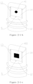
- the receiving portion top is in an open state to form the receiving portion top opening 11, as shown in Fig. 2-1-a .
- the opening 11 provides an entrance for the insertion of the sensor 2, which facilitates the insertion of the sensor 2.
- the receiving portion top opening is open in the following embodiments.
- the electrode region 22 of the implantable analyte sensor 2 is implanted under human skin via the through hole 5, the interface on the back side of the implantable analyte sensor 2 is electrically connected to the sensor current data generation device through the conductive path 400, and other existing conductive materials can also be added between the conductive path 400 and the sensor current data generation device for electrical connection.
- the interface on the front side of the implantable analyte sensor 2 is electrically connected by an existing conductive material, and the conductive material includes but is not limited to graphite, a conductive tape and a copper wire.
- Data is exchanged between the signal transmission device and the sensor current data generation device, and the two can exchange data by means of a data line or wireless signals (existing wireless data exchange modes such as Bluetooth, WiFi, and radio-frequency signals).
- a data line or wireless signals existing wireless data exchange modes such as Bluetooth, WiFi, and radio-frequency signals.
- the signal transmission device requires corresponding components in the prior art.
- the sensor current data generation device controls the implantable analyte sensor through electrical signals to test subcutaneous analytes, and receives data generated by the implantable analyte sensor 2, and the received data is transmitted to the data processing unit by the signal transmission device for processing and display.
- a micro processing chip on the market can achieve this function.
- the data processing unit may be an intelligent terminal (a smart phone, a computer, a tablet, etc.), or a component including a display screen and a data processing chip, wherein the data processing chip is installed in the housing, and the display screen is installed on the housing.
- an intelligent terminal a smart phone, a computer, a tablet, etc.
- a component including a display screen and a data processing chip wherein the data processing chip is installed in the housing, and the display screen is installed on the housing.
- the present invention provides a fixing member for an implantable analyte sensor, which is used for fixing the analyte sensor, and is particularly suitable for a sensor with double-sided microelectrodes.
- the receiving end 41 of the conductive path 400 is used to contact the electrode interface 23 on the back side of the sensor 20 to receive information from the sensor 2.
- the output end 42 is used to output the information to other electronic components.
- the conductive path 400 has two output ends, as shown in Fig. 4-5 .
- the output ends are a first output end 421 and an output end 422.
- the conductive path 400 can have three or more output ends.
- the number of the conductive path 400 is at least one, or may be two or more, and the number is related to the number of the electrode interface on the back side of the sensor 2. If one temperature sensing electrode is added on the back side, one conductive path needs to be added. When the number of the conductive paths 400 is more than one, the conductive paths 400 may be arranged in the same layout mode, or in multiple modes.
- the material of the conductive path 400 may be a conductive metal, a conductive polymer, or other conductive material (such as graphite), and the shape thereof may be selectively linear, columnar, flaky, etc.
- the back electrode refers to an electrode facing the receiving portion inner wall 14.
- the right side of Fig. 1 is regarded as the back side.
- the reference electrode 143 is distributed on the back side
- the counter electrode 242 and the working electrode 241 are distributed on the other side.
- the counter electrode 242, the working electrode 241, and the reference electrode 243 are common technologies in the field of electrochemical analysis, and have no other creative technical features.
- the receiving portion 1 is composed of receiving portion side walls 13, a receiving portion top opening 11, a receiving portion bottom 12 and a receiving portion inner wall 14, a groove 6 is provided in the receiving portion 1, and the groove 6 is used to fit an edge of the interface region 21 of the sensor.
- the groove 6 is located on the receiving portion bottom 12 and is in contact with the receiving portion inner wall 14, and the opening of the through hole 5 is located in the groove 6, as shown in Fig. 3-1 and Fig. 3-3 , so as to fit the lower edge of the interface region 21 and further fix and limit the interface region 21.
- a groove 6 is provided on one receiving portion side wall 13 (as shown in Figs. 3-1 and 3-3 ) or two receiving portion side walls 13 (as shown in Figs. 2-1-a and 3-2 ) of the receiving portion 1, and the groove 6 is in contact with the receiving portion inner wall 14.
- the groove 6 on the receiving portion side wall 13 can play a guiding role, which facilitates the entry of the electrode region 22 into the through hole 5.
- the groove 6 can further fix and limit the movement of the interface region 21.
- the fixing member may further include a connecting portion (not shown in the figures).
- the connecting portion is used to fix the fixing member to the base of the analyte detection device, and the fixing mode may be a removable mode (buckling, screwing, or inserting and extracting) or a non-removable mode (bonding with an adhesive, or integrating with the base).
- the fixing mode of buckles is optimal.
- the senor 2 can be directly inserted into a corresponding position of the fixing member or extracted therefrom. In this way, the sensor 2 can be quickly replaced, which not only reduces the time for replacement, but also simplifies the steps of replacement.
- the analyte detection device refers to a device that includes a detection unit, a signal transmission device and a power source, and is fixed to the skin by bonding, binding, or the like.
- the fixing member may further include a sealing ring 7, for example, an O-shaped rubber ring as shown in Fig. 2-1 , which can also be replaced by a hydrophobic film or other existing materials with a sealing effect.
- the number of the sealing ring is at least one, and the sealing ring is arranged on the supporting portion side wall in a surrounding manner and located below the receiving portion bottom.
- the sealing ring 7 is used for waterproofing, specifically, to prevent water from permeating (into the inside of) the monitoring device when the fixed part of the human body touches water (for example, bathing, swimming, etc.) to affect the internal electronic components.
- the number of the groove 6 is 1 to 3, and the groove(s) 6 is/are located on the receiving portion side walls 13, or the receiving portion bottom 12, or a combination of the two.
- the distribution of some grooves 6 can be referred to Figs. 2-1 , 2-2 and 3-1 to 3-3 .
- the groove 6 is used for positioning the interface region 21 of the sensor 2 and limiting the movement of the interface region 21, and the groove 6 on the side wall 13 also has an effect of guiding the insertion of the interface region 21. As shown in Figs.
- the width y of the receiving portion inner wall 14 is greater than the length of the interface region 21, and the difference is more than 0 mm and less than or equal to 0.5 mm, and further can be 0.05 to 0.2 mm, preferably 0.1 mm, which prevents difficult insertion caused by too small difference, and also prevents the reduction of the effect of limiting the interface region 21 due to too large difference.
- the width y of the receiving portion inner wall is within a numerical range of 2 to 5 mm.
- the first end portion 41 When the conductive sheet 401 is connected to the first end portion 41, the first end portion 41 can be better conductively connected to the electrode interface 23 of the back electrode; and when the conductive sheet 401 is connected to the second end portion 42, the conductivity between the second end portion 42 and the sensor current data generation device is more stable and excellent.
- the conductive path 400 can penetrate the receiving portion 1 of the fixing member, so that the two ports of the conductive path 400 are respectively located on the receiving portion inner wall 14 and the supporting portion side wall 32/ supporting portion top 31.
- the fixing member is provided with a conductive hole 40, as shown in Figs. 2-1-a , 2-1-d , and 3-1 to 3-3 .
- the conductive hole 40 is used for the conductive path 400 to pass through, so that the first end portion 41 of the conductive path 400 points to the receiving portion inner wall 14 of the fixing member.
- a conductive sheet 401 is provided between the first end portion 41 and the back electrode of the sensor 2, the electrode interface 23 of the back electrode is electrically connected to the conductive sheet 401, the first end portion 41 is electrically connected to the conductive sheet 401, and the conductive sheet 401 is located on the surface of the receiving portion inner wall 14, as shown in Fig. 2-1-g .
- the second end portion 42 is located on the back side of the supporting portion side wall 32 of the receiving portion 1, so as to be electrically connected to the interface of the sensor current data generation device, as shown in Fig. 2-1-e .
- a conductive sheet 401 is provided on the back side of the supporting portion side wall 32 opposite to the receiving portion 1, the second end portion 42 is electrically connected to the conductive sheet 401, and the conductive sheet 401 can also be electrically connected to the interface of the sensor current data generation device and increase the connection strength of electrical signals, as shown in Fig. 2-1-h .
- the conductive hole 40 is of a curve or a broken line
- the first end portion 41 of the conductive path 400 points to the receiving portion inner wall 14
- the second end portion 42 points to the supporting portion side wall 32 or the supporting portion top 31, as shown in Fig. 5 .
- a conductive sheet 401 is provided between the first end portion 41 and the back electrode of the sensor 2, a conductive sheet 401 is also provided on the back side of the fixing member, the second end portion 42 is electrically connected to the conductive sheet 401, and the effect after the sensor 2 is inserted into the fixing member 10 is as shown in Figs. 2-1-g and 2-1-h .
- a part of the conductive channel 400 may penetrate the supporting portion 3, and the other part may be located on the outer surface of the supporting portion side wall 32.
- the first end portion 41 of the conductive channel 400 is located on the receiving portion inner wall 14, and the second end portion 42 is located on the lateral side or back side of the supporting portion side wall 32.
- a part (the black dotted line part) of the conductive path 400 penetrates through the fixing member, and the other part (the black solid line part) extends along the surface of the supporting portion side wall 32 to the back side of the supporting portion side wall 32, or to the supporting portion top 31 or the lateral side of the supporting portion side wall 32, and vice versa.
Landscapes
- Health & Medical Sciences (AREA)
- Life Sciences & Earth Sciences (AREA)
- Physics & Mathematics (AREA)
- Surgery (AREA)
- General Health & Medical Sciences (AREA)
- Engineering & Computer Science (AREA)
- Biomedical Technology (AREA)
- Heart & Thoracic Surgery (AREA)
- Medical Informatics (AREA)
- Molecular Biology (AREA)
- Biophysics (AREA)
- Animal Behavior & Ethology (AREA)
- Pathology (AREA)
- Public Health (AREA)
- Veterinary Medicine (AREA)
- Optics & Photonics (AREA)
- Chemical & Material Sciences (AREA)
- Chemical Kinetics & Catalysis (AREA)
- General Chemical & Material Sciences (AREA)
- Emergency Medicine (AREA)
- Measurement Of The Respiration, Hearing Ability, Form, And Blood Characteristics Of Living Organisms (AREA)
Description
- The present invention relates to a fixing member for an implantable analyte sensor and an implantable analyte sensor system including the fixing member, and belongs to the technical field of electroanalytical chemical detection.
- With regard to conventional analyte detection technologies, taking a patient suffering from diabetes as an example, the glucose content of blood needs to be regularly tested, then a puncture needle is required to puncture the skin to collect blood, and the blood is tested by means of colorimetry, electrochemical analysis or optical detection. These methods are not only cumbersome, but also increase patient's burden. Therefore, in order to solve the above problems and continuously test changes in the concentrations of analytes in the body, many devices for continuous analyte test have been developed. In the prior art, the electrochemical analysis is usually used. Accordingly, a sensor used for testing analytes is equipped with at least a working electrode, a counter electrode and a reference electrode. These electrodes are generally on the same side, or distributed on two opposite sides. For example, patent Nos.
CN102665549B ,CN104887242A , andCN103750819B disclose a method for distributing electrodes on the same side of a sensor. This distribution method requires multiple electrodes to be distributed in a limited area, which undoubtedly increases the process difficulty and technical requirements. For another example, patent Nos.CN102469964B andUS9795326B2 - Further examples of fixing members can be found in
US 2011/060196 A1 and inUS 2011/256024 A1 . - This method can reduce the process difficulty of sensor production, but a fixing member for fixing the sensor needs to be provided with electric contacts on different sides, thereby increasing the complexity of the fixing member or the difficulty in mounting the sensor.
- In view of the shortcomings of the prior art, the present invention provides a fixing member for an implantable analyte sensor, which is particularly suitable for a sensor with double-sided microelectrodes. The basic idea of the present invention is to provide a first end portion on a side facing a microelectrode (a back electrode), wherein the first end portion is electrically connected to an interface of the back electrode. In addition, a second end portion is electrically connected to the first end portion, and the second end portion is connected to a corresponding interface of a sensor current data generation device, so that the sensor current data generation device can be connected to the microelectrodes of the sensor with a double-sided structure for testing analytes.
- The present invention provides a fixing member for an implantable analyte sensor, the fixing member includes a supporting portion, a receiving portion, a conductive path and a through hole; the supporting portion includes supporting portion side walls, a supporting portion top and a supporting portion bottom; the receiving portion is located in the supporting portion side walls in a recessed manner, and the receiving portion includes receiving portion side walls, a receiving portion inner wall, a receiving portion bottom and a receiving portion top; the conductive path includes an input end and an output end, the input end is located on the receiving portion inner wall, and the output end is located on a surface of the supporting portion; the input end and the output end are electrically connected by a connecting portion; and an opening of the through hole is located at the receiving portion bottom, and the other opening is located at the supporting portion bottom.
- Preferably, the receiving portion top is open.
- Preferably, at least a part of the connecting portion is located in the supporting portion. Preferably, the input end protrudes from the receiving portion inner wall.
- Preferably, the output end protrudes from the surface of the supporting portion. Preferably, at least a part of the connecting portion is located on the surface of the supporting portion.
- Preferably, a conductive sheet is provided on the receiving portion inner wall, and the conductive sheet is electrically connected to the input end; or a conductive sheet is provided on the surface of the supporting portion, and the conductive sheet is electrically connected to the output end; or a conductive sheet is respectively provided on the receiving portion inner wall and the surface of the supporting portion, and the conductive sheets are electrically connected to the input end and the output end, respectively.
- Preferably, a groove is provided on the receiving portion bottom; or a groove is provided on the receiving portion side wall; or a groove is provided on the receiving portion bottom and the receiving portion side wall.
- Preferably, one opening of the through hole is provided in the groove at the receiving portion bottom.
- The present invention provides another fixing member for an implantable analyte sensor, which is used for a sensor with double-sided microelectrodes, the fixing member includes a supporting portion, a receiving portion, a conductive path and a through hole; the receiving portion is composed of a receiving portion top, receiving portion side walls, a receiving portion bottom and a receiving portion inner wall, and the supporting portion is connected to the receiving portion bottom to form a receiving portion bottom platform; the through hole is located on the supporting portion, with one end opened to the receiving portion bottom platform; the conductive path is located on the receiving portion; and the conductive path includes at least two end portions.
- In some preferred embodiments, the conductive path includes a first end portion and a second end portion, and the second end portion is electrically connected to the first end portion.
- In some preferred embodiments, the conductive path penetrates the receiving portion. In some preferred embodiments, the conductive path is located on an outer surface of the receiving portion.
- In some preferred embodiments, a part of the conductive path penetrates the receiving portion, and the other part is located on the outer surface of the receiving portion.
- In some preferred embodiments, the receiving portion is provided with a conductive hole for receiving the conductive path.
- In some preferred embodiments, the first end portion is located on the receiving portion inner wall, and the second end portion is located on the receiving portion top or side wall.
- In some preferred embodiments, the conductive path further includes a third end portion located on the receiving portion; and the third end portion is electrically connected to the second end portion and the first end portion.
- In some preferred embodiments, the receiving portion is provided with one to three grooves; and the grooves are located on the receiving portion inner wall or bottom.
- In some preferred embodiments, the fixing member further includes a conductive sheet located on the receiving portion; and the conductive sheet is electrically connected to an end portion of the conductive path.
- In some preferred embodiments, a sealing ring is further included, and the sealing ring surrounds the supporting portion side wall.
- In some preferred embodiments, a connecting portion is further included, and the connecting portion is connected to the supporting portion.
- On the other hand, the present invention further provides an implantable analyte sensor system, including a detection unit, a signal transmission device, and a data processing unit;
- the detection unit and the signal transmission device are fixed in a housing, and a power source is further provided in the housing to supply power to electronic components in the housing; and
- the detection unit includes an implantable analyte sensor, the fixing member for fixing the implantable analyte sensor according to the present invention, and a sensor current data generation device.
- Specifically, the fixing member includes a supporting portion, a receiving portion, a conductive path and a through hole; the receiving portion is composed of a receiving portion top, receiving portion side walls, a receiving portion bottom and a receiving portion inner wall, and the supporting portion is connected to the receiving portion bottom to form a receiving portion bottom platform; the through hole is located on the supporting portion, with one end opened to the receiving portion bottom platform; the conductive path is located on the receiving portion; and the conductive path includes at least two end portions.
- In some preferred embodiments, the fixing member is fixed to a base of the housing through a connecting portion connected to the supporting portion.
- In some preferred embodiments, the conductive path includes a first end portion and a second end portion, and the second end portion is electrically connected to the first end portion.
- In some preferred embodiments, the conductive path penetrates the receiving portion. In some preferred embodiments, the conductive path is located on an outer surface of the receiving portion.
- In some preferred embodiments, a part of the conductive path penetrates the receiving portion, and the other part is located on the outer surface of the receiving portion.
- In some preferred embodiments, the receiving portion is provided with a conductive hole for receiving the conductive path.
- In some preferred embodiments, the first end portion is located on the receiving portion inner wall, and the second end portion is located on the receiving portion top or side wall.
- In some preferred embodiments, the conductive path further includes a third end portion located on the receiving portion; and the third end portion is electrically connected to the second end portion and the first end portion.
- In some preferred embodiments, the receiving portion is provided with one to three grooves; and the grooves are located on the receiving portion inner wall or bottom.
- In some preferred embodiments, the fixing member further includes a conductive sheet located on the receiving portion; and the conductive sheet is electrically connected to an end portion of the conductive path.
- The beneficial effects of the present invention are: the fixing member relatively reduces the difficulty in preparing the sensor with double-sided microelectrodes, and can effectively reduce the cost. In addition, the fixing member is simple in structure and easy to manufacture, and the replacement of the sensor is simple and convenient. Moreover, the detection efficiency of the implantable analyte sensor system with the fixing member is improved.
-
-
Fig. 1 is a schematic structural diagram of front and back sides of a sensor; - In
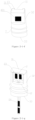
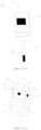
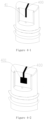
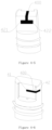
Fig. 2-1 (Figs. 2-1-a ,2-1-b, 2-1-c ,2-1-d, 2-1-e ,2-1-f, 2-1-g , and2-1-h ),Figs. 2-1-a, 2-1-b and 2-1-c are schematic diagrams of a front side of a fixing member in different embodiments,Figs. 2-1-d, 2-1-e and2-1-f are schematic diagrams of a back side of the fixing member in different embodiments, andFigs. 2-1-g and2-1-h are schematic diagrams of a combination of the fixing member and the sensor; andFig. 2-2 (Figs. 2-2-a and2-2-b ) shows schematic diagrams of the front side of the fixing member in different embodiments; -
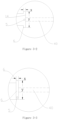
Figs. 3-1 ,3-2 and 3-3 are top views of the fixing member; -
Figs. 4-1 to 4-8 are schematic diagrams of the fixing member in different embodiments; -
Figs. 4-9 and 4-10 are schematic diagrams of the combination of the fixing member and the sensor; -
Fig. 5 is a top view showing that a conductive path partially penetrates a receiving portion and is partially located on a surface of the receiving portion; -
Fig. 6 is a schematic diagram of an implantable analyte sensor system. - The following embodiments further describe the present invention. These embodiments are not used to limit the scope of the present invention, but to provide a further understanding of the present invention.
- An implantable analyte sensor system (which can be used to continuously monitor the concentrations of analytes in human blood, the analytes including but not limited to glucose, sodium ions and potassium ions), as shown in
Fig. 6 , includes a detection unit, a signal transmission device, and a data processing unit. - The detection unit and the signal transmission device are fixed in a housing, the housing plays a role in protecting internal electronic components, and a power source (not shown in the figure) is further provided in the housing to supply power to the electronic components in the housing.
- The detection unit includes an
implantable analyte sensor 2, a fixing member for fixing the implantable analyte sensor, and a sensor current data generation device. Thesensor 2 in the present invention is preferably a sensor with double-sided microelectrodes, and a sensor with single-sided electrodes is also applicable. - Generally, as shown in
Fig. 1 , thesensor 2 with double-sided microelectrodes includes a back side (the side in contact with the inner wall of a receiving portion is referred to as the back side) and a front side, anelectrode interface 23 is respectively provided at upper ends of the front and back sides, and functional electrodes, such as a workingelectrode 241, acounter electrode 242 and areference electrode 243, are provided at lower ends, wherein the workingelectrode 241 and thecounter electrode 242 are placed on the front side of thesensor 2, and thereference electrode 243 is placed on the back side of thesensor 2. The workingelectrode 241, thecounter electrode 242 and thereference electrode 243 are respectively connected to the electrode interfaces 23 through conductive traces, so that the workingelectrode 241, thecounter electrode 242 and thereference electrode 243 transmit signals to other related components through the electrode interfaces 23. The part where the functional electrodes are placed is summarized as anelectrode region 22, and the part where the electrode interfaces 23 are placed is summarized as aninterface region 21. Theelectrode region 22 and theinterface region 21 are both marked with boxes in the figure. The sensor with double-sided electrodes described above is only of a relatively common structure, and a person skilled in the art can selectively change the arrangement of these functional electrodes, or add other functional electrodes for measuring pH, temperature, etc. - As shown in
Figs. 2-1-b ,2-1-e ,2-2-a ,2-2-b ,4-1 ,4-3 and4-6 , the fixing member for the implantable analyte sensor according to the present invention includes a supportingportion 3, a receiving portion 1, aconductive path 400 and a throughhole 5. The supportingportion 3 is composed of a supportingportion top 31, supportingportion side walls 32 and a supportingportion bottom 33. The receiving portion 1 is arranged on the supportingportion side walls 32 in a recessed manner and is preferably close to the supportingportion top 31, and the receiving portion 1 is used to receive theinterface region 21 of thesensor 2. The receiving portion 1 includes receivingportion side walls 13, a receivingportion bottom 12, a receiving portioninner wall 14, and a receiving portion top. The receiving portion top is arranged opposite to the receiving portion bottom, and can be closed or open. The receivingportion side walls 13 and the receiving portion bottom 12 are respectively used to limit the left and right movement of theinterface region 21 of thesensor 2 and the movement of the supportingportion bottom 33. - The through
hole 5 extends from an opening in the receiving portion bottom 12 to an opening in the supporting portion bottom 33 in a penetrating manner. Accordingly, theelectrode region 22 of thesensor 2 enters from the receivingportion bottom 12, and finally extends out from the supportingportion bottom 33. Theconductive path 400 includes a receivingend 41 and anoutput end 42, the receivingend 41 and theoutput end 42 are connected by a connecting portion made of a conductive material. The total number of the receivingend 41 and theoutput end 42 is not less than two, the receivingend 41 is used to receive data information from thesensor 2, and theoutput end 42 outputs the information to other electronic components, such as a central processing unit. The receivingend 41 is located on the receiving portioninner wall 14, theoutput end 42 is located on the supportingportion side wall 32, and the receivingend 41 and theoutput end 42 are electrically connected. - In one embodiment, as shown in
Figs. 2-1-b ,2-1-e ,2-2-a ,2-2-b ,4-1 ,4-3 and4-6, the receiving portion 1 is composed of a receivingportion top opening 11, receivingportion side walls 13, a receivingportion bottom 12, and a receiving portioninner wall 14. During use, theinterface region 21 of thesensor 2 enters from the receivingportion top opening 11 and moves down along the receivingportion side wall 13, while theelectrode region 22 below theinterface region 21 enters from the throughhole 5 of the receivingportion bottom 12. Finally, theinterface region 21 is blocked by the receivingportion bottom 12 and stops moving, while theelectrode region 22 extends out from the supportingportion bottom 33 and is located below the supportingportion bottom 33. - The receiving portion top is in an open state to form the receiving
portion top opening 11, as shown inFig. 2-1-a . Theopening 11 provides an entrance for the insertion of thesensor 2, which facilitates the insertion of thesensor 2. The receiving portion top opening is open in the following embodiments. - The fixing member is fixed on a base of the housing, and the base is provided with a hole corresponding to the through
hole 5 for theelectrode region 22 of theimplantable analyte sensor 2 to pass through. The test electrodes such as the workingelectrode 241, thecounter electrode 242 and thereference electrode 243 that are implanted in the human body are summarized as theelectrode region 22. - The
electrode region 22 of theimplantable analyte sensor 2 is implanted under human skin via the throughhole 5, the interface on the back side of theimplantable analyte sensor 2 is electrically connected to the sensor current data generation device through theconductive path 400, and other existing conductive materials can also be added between theconductive path 400 and the sensor current data generation device for electrical connection. The interface on the front side of theimplantable analyte sensor 2 is electrically connected by an existing conductive material, and the conductive material includes but is not limited to graphite, a conductive tape and a copper wire. Data is exchanged between the signal transmission device and the sensor current data generation device, and the two can exchange data by means of a data line or wireless signals (existing wireless data exchange modes such as Bluetooth, WiFi, and radio-frequency signals). In order to implement any of the data transmission modes in the prior art, the signal transmission device requires corresponding components in the prior art. - Data is exchanged between the data processing unit and the signal transmission device, and the two can exchange data by means of a data line or wireless signals.
- The sensor current data generation device controls the implantable analyte sensor through electrical signals to test subcutaneous analytes, and receives data generated by the
implantable analyte sensor 2, and the received data is transmitted to the data processing unit by the signal transmission device for processing and display. For example, a micro processing chip on the market can achieve this function. - The data processing unit may be an intelligent terminal (a smart phone, a computer, a tablet, etc.), or a component including a display screen and a data processing chip, wherein the data processing chip is installed in the housing, and the display screen is installed on the housing.
- In the above-mentioned implantable analyte sensor system, except the fixing member, other components and connection mode have no creative technical features.
- The present invention provides a fixing member for an implantable analyte sensor, which is used for fixing the analyte sensor, and is particularly suitable for a sensor with double-sided microelectrodes.
- The cross section of the through
hole 5 may be triangular, circular or semicircular, for an implantable portion (including the electrode region) of thesensor 2 to pass through. The implantable portion is inserted into the human skin after passing through the throughhole 5, and the number of the throughhole 5 is one. The throughhole 5 is equidistant from the two receivingportion side walls 13 of the receiving portion 1, as shown inFigs. 3-1 and3-2 ; and it can also be offset to one side, as shown inFig. 3-3 . Since thesensor 2 may not be enough to pierce the skin, it needs to be combined with a common puncture needle in the art, so that the test electrodes of thesensor 2 can be successfully implanted under the skin. - As shown in
Figs. 2-1-b ,2-1-e ,2-2-a ,2-2-b ,4-1 ,4-3 and4-6, the receivingend 41 of theconductive path 400 is used to contact theelectrode interface 23 on the back side of the sensor 20 to receive information from thesensor 2. Theoutput end 42 is used to output the information to other electronic components. - In some embodiments, the
conductive path 400 has two output ends, as shown inFig. 4-5 . In this embodiment, the output ends are afirst output end 421 and anoutput end 422. Or theconductive path 400 can have three or more output ends. The number of theconductive path 400 is at least one, or may be two or more, and the number is related to the number of the electrode interface on the back side of thesensor 2. If one temperature sensing electrode is added on the back side, one conductive path needs to be added. When the number of theconductive paths 400 is more than one, theconductive paths 400 may be arranged in the same layout mode, or in multiple modes. The material of theconductive path 400 may be a conductive metal, a conductive polymer, or other conductive material (such as graphite), and the shape thereof may be selectively linear, columnar, flaky, etc. - In the following embodiments, the present invention takes a
conductive path 400 having aninput end 41 and anoutput end 42, specifically afirst end portion 41 and asecond end portion 42, as an example. Thefirst end portion 41 is located on the receiving portioninner wall 14 and between theelectrode interface 23 of the back electrode and the fixing member, and thesecond end portion 42 is located on the other side of the fixing member and connected to corresponding interface of the sensor current data generation device. In order to better contact theelectrode interface 23, thefirst end portion 41 needs to slightly protrude from the receiving portioninner wall 14, and the protruding distance is more than 0 mm, preferably 0.01 to 1 mm, and more preferably 0.01 to 0.5 mm. - The back electrode refers to an electrode facing the receiving portion
inner wall 14. In the present invention, the right side ofFig. 1 is regarded as the back side. Of course, if the left side ofFig. 1 faces the receiving portioninner wall 14, this side is the back side. The technical solutions of the present invention are all described by taking the right side ofFig. 1 as the back side as an example, the reference electrode 143 is distributed on the back side, and thecounter electrode 242 and the workingelectrode 241 are distributed on the other side. In addition, thecounter electrode 242, the workingelectrode 241, and thereference electrode 243 are common technologies in the field of electrochemical analysis, and have no other creative technical features. - In a preferred embodiment, referring to
Figs. 2-1 ,2-2 ,3-1 to 3-3 , and4-1 to 4-10 , the receiving portion 1 is composed of receivingportion side walls 13, a receivingportion top opening 11, a receivingportion bottom 12 and a receiving portioninner wall 14, agroove 6 is provided in the receiving portion 1, and thegroove 6 is used to fit an edge of theinterface region 21 of the sensor. As a preference, thegroove 6 is located on the receivingportion bottom 12 and is in contact with the receiving portioninner wall 14, and the opening of the throughhole 5 is located in thegroove 6, as shown inFig. 3-1 andFig. 3-3 , so as to fit the lower edge of theinterface region 21 and further fix and limit theinterface region 21. As another preference, agroove 6 is provided on one receiving portion side wall 13 (as shown inFigs. 3-1 and3-3 ) or two receiving portion side walls 13 (as shown inFigs. 2-1-a and3-2 ) of the receiving portion 1, and thegroove 6 is in contact with the receiving portioninner wall 14. When thesensor 2 is inserted into the fixing member, thegroove 6 on the receivingportion side wall 13 can play a guiding role, which facilitates the entry of theelectrode region 22 into the throughhole 5. After thesensor 2 is inserted into the fixing member, thegroove 6 can further fix and limit the movement of theinterface region 21. - In the present invention, the fixing member may further include a connecting portion (not shown in the figures). The connecting portion is used to fix the fixing member to the base of the analyte detection device, and the fixing mode may be a removable mode (buckling, screwing, or inserting and extracting) or a non-removable mode (bonding with an adhesive, or integrating with the base). The fixing mode of buckles is optimal.
- During use, the
sensor 2 can be directly inserted into a corresponding position of the fixing member or extracted therefrom. In this way, thesensor 2 can be quickly replaced, which not only reduces the time for replacement, but also simplifies the steps of replacement. - The analyte detection device refers to a device that includes a detection unit, a signal transmission device and a power source, and is fixed to the skin by bonding, binding, or the like.
- In the present invention, the fixing member may further include a
sealing ring 7, for example, an O-shaped rubber ring as shown inFig. 2-1 , which can also be replaced by a hydrophobic film or other existing materials with a sealing effect. The number of the sealing ring is at least one, and the sealing ring is arranged on the supporting portion side wall in a surrounding manner and located below the receiving portion bottom. The sealingring 7 is used for waterproofing, specifically, to prevent water from permeating (into the inside of) the monitoring device when the fixed part of the human body touches water (for example, bathing, swimming, etc.) to affect the internal electronic components. - The number of the
groove 6 is 1 to 3, and the groove(s) 6 is/are located on the receivingportion side walls 13, or the receivingportion bottom 12, or a combination of the two. The distribution of somegrooves 6 can be referred toFigs. 2-1 ,2-2 and3-1 to 3-3 . Thegroove 6 is used for positioning theinterface region 21 of thesensor 2 and limiting the movement of theinterface region 21, and thegroove 6 on theside wall 13 also has an effect of guiding the insertion of theinterface region 21. As shown inFigs. 3-1 to 3-3 , the width x of thegroove 6 is greater than the edge thickness of theinterface region 21, and the difference is more than 0 mm and less than or equal to 0.5 mm, and further can be 0.05 to 0.2 mm, preferably 0.1 mm, which prevents difficult insertion caused by too small difference, and also prevents the reduction of the effect of limiting theinterface region 21 due to too large difference. Similarly, the width y of the receiving portioninner wall 14 is greater than the length of theinterface region 21, and the difference is more than 0 mm and less than or equal to 0.5 mm, and further can be 0.05 to 0.2 mm, preferably 0.1 mm, which prevents difficult insertion caused by too small difference, and also prevents the reduction of the effect of limiting theinterface region 21 due to too large difference. The width y of the receiving portion inner wall is within a numerical range of 2 to 5 mm. - As shown in
Figs. 2-1-c ,2-1-f ,2-1-h ,4-2 ,4-4 ,4-7 ,4-8 and4-10 , the material used forconductive sheets 401 may be a conductive metal, a conductive polymer, or other conductive material (such as graphite). The number of theconductive sheets 401 may be one or more. The conductive sheet(s) 401 is/are electrically connected to one or more end portions of theconductive path 400, respectively. When the connection strength needs to be increased, the conductive sheet(s) 6 can be electrically connected to thefirst end portion 41 and/or thesecond end portion 42 by means of a conductive bonding material (a conductive glue, or a conductive tape). When theconductive sheet 401 is connected to thefirst end portion 41, thefirst end portion 41 can be better conductively connected to theelectrode interface 23 of the back electrode; and when theconductive sheet 401 is connected to thesecond end portion 42, the conductivity between thesecond end portion 42 and the sensor current data generation device is more stable and excellent. - In the present invention, the
conductive path 400 can penetrate the receiving portion 1 of the fixing member, so that the two ports of theconductive path 400 are respectively located on the receiving portioninner wall 14 and the supportingportion side wall 32/ supportingportion top 31. Specifically, the fixing member is provided with aconductive hole 40, as shown inFigs. 2-1-a ,2-1-d , and3-1 to 3-3 . Theconductive hole 40 is used for theconductive path 400 to pass through, so that thefirst end portion 41 of theconductive path 400 points to the receiving portioninner wall 14 of the fixing member. Thesecond end portion 42 of theconductive path 400 is located on the other surface of the supportingportion 3, for example, thesecond end portion 42 is located on the back side of the supportingportion side wall 32 opposite to the receiving portion 1 inFig. 2-1-e . But this does not mean that thesecond end portion 42 must be located on this surface. Thesecond end portion 42 may also be located on a lateral side of the supportingportion side wall 32 opposite to the receiving portion 1, as shown inFig. 2-2-a . And in another embodiment, theconductive path 400 penetrates the supportingportion 3, and thesecond end portion 42 is located at the supportingportion top 31, as shown inFig. 2-2-b . - In one embodiment, a
conductive sheet 401 is provided between thefirst end portion 41 and the back electrode of thesensor 2, theelectrode interface 23 of the back electrode is electrically connected to theconductive sheet 401, thefirst end portion 41 is electrically connected to theconductive sheet 401, and theconductive sheet 401 is located on the surface of the receiving portioninner wall 14, as shown inFig. 2-1-g . - In one embodiment, the
second end portion 42 is located on the back side of the supportingportion side wall 32 of the receiving portion 1, so as to be electrically connected to the interface of the sensor current data generation device, as shown inFig. 2-1-e . - In one embodiment, a
conductive sheet 401 is provided on the back side of the supportingportion side wall 32 opposite to the receiving portion 1, thesecond end portion 42 is electrically connected to theconductive sheet 401, and theconductive sheet 401 can also be electrically connected to the interface of the sensor current data generation device and increase the connection strength of electrical signals, as shown inFig. 2-1-h . - In one embodiment, the
conductive hole 40 is of a curve or a broken line, thefirst end portion 41 of theconductive path 400 points to the receiving portioninner wall 14, and thesecond end portion 42 points to the supportingportion side wall 32 or the supportingportion top 31, as shown inFig. 5 . - In a preferred embodiment, a
conductive sheet 401 is provided between thefirst end portion 41 and the back electrode of thesensor 2, aconductive sheet 401 is also provided on the back side of the fixing member, thesecond end portion 42 is electrically connected to theconductive sheet 401, and the effect after thesensor 2 is inserted into the fixing member 10 is as shown inFigs. 2-1-g and2-1-h . - In the present invention, the
conductive path 400 may be located on the outer surface of the fixing member, and the two ports of theconductive path 400 are respectively located on the receiving portioninner wall 14 and the supportingportion side wall 32 or the supportingportion top 31, that is, one port is located on the receiving portioninner wall 14, and the other port is located on the supportingportion side wall 32 or the supportingportion top 31. At this time, noconductive hole 40 is provided in the fixing member, and theconductive path 400 is distributed along the surface of the receiving portion fixing member, so that thefirst end portion 41 of theconductive path 400 is located on the receiving portion inner wall 14 (as shown inFigs. 4-1, 4-2 ,4-7, and 4-8 ), thesecond end portion 42 is located on the supporting portion top 31 (as shown inFig. 4-3 ), or thesecond end portion 42 is located on the lateral side of the supportingportion side wall 32 opposite to the receiving portion 1 (as shown inFigs. 4-6 and4-7 ), or thesecond end portion 42 is located on the back side of the supportingportion side wall 32 opposite to the receiving portion 1 (as shown inFigs. 4-4 ,4-5 and4-10 ). In order to increase the adhesion strength of theconductive path 400 on the surface of the fixing member, an adhesive layer can be provided between theconductive path 400 and the surface of the fixing member or the two are bonded with an adhesive. In addition, the two may be fixed by inlaying. - In the present invention, a part of the
conductive channel 400 may penetrate the supportingportion 3, and the other part may be located on the outer surface of the supportingportion side wall 32. In addition, thefirst end portion 41 of theconductive channel 400 is located on the receiving portioninner wall 14, and thesecond end portion 42 is located on the lateral side or back side of the supportingportion side wall 32. For example, as shown inFig. 5 , a part (the black dotted line part) of theconductive path 400 penetrates through the fixing member, and the other part (the black solid line part) extends along the surface of the supportingportion side wall 32 to the back side of the supportingportion side wall 32, or to the supportingportion top 31 or the lateral side of the supportingportion side wall 32, and vice versa.
Claims (10)
- A fixing member for an implantable analyte sensor, wherein,the fixing member comprises a supporting portion, a receiving portion, a conductive path and a through hole;the supporting portion comprises supporting portion side walls, a supporting portion top and a supporting portion bottom;the receiving portion is located in the supporting portion side walls in a recessed manner, and the receiving portion comprises receiving portion side walls, a receiving portion inner wall, a receiving portion bottom and a receiving portion top;the conductive path comprises an input end and an output end, the input end is located on the receiving portion inner wall, and the output end is located on a surface of the supporting portion; the input end and the output end are electrically connected by a connecting portion; andan opening of the through hole is located at the receiving portion bottom, and the other opening is located at the supporting portion bottom.
- The fixing member for an implantable analyte sensor according to claim 1, wherein the receiving portion top is open.
- The fixing member for an implantable analyte sensor according to claim 2, wherein at least a part of the connecting portion is located in the supporting portion.
- The fixing member for an implantable analyte sensor according to claim 3, wherein, the input end protrudes from the receiving portion inner wall.
- The fixing member for an implantable analyte sensor according to claim 3, wherein, the output end protrudes from the surface of the supporting portion.
- The fixing member for an implantable analyte sensor according to claim 2, wherein, at least a part of the connecting portion is located on the surface of the supporting portion.
- The fixing member for an implantable analyte sensor according to any one of claims 1-6, wherein,a conductive sheet is provided on the receiving portion inner wall, and the conductive sheet is electrically connected to the input end;or a conductive sheet is provided on the surface of the supporting portion, and the conductive sheet is electrically connected to the output end;or a conductive sheet is respectively provided on the receiving portion inner wall and the surface of the supporting portion, and the conductive sheets are electrically connected to the input end and the output end, respectively.
- The fixing member for an implantable analyte sensor according to any one of claims 1-6, wherein,a groove is provided on the receiving portion bottom;or a groove is provided on the receiving portion side wall;or a groove is provided on the receiving portion bottom and the receiving portion side wall.
- The fixing member for an implantable analyte sensor according to claim 7, wherein, one opening of the through hole is provided in the groove at the receiving portion bottom.
- An implantable analyte sensor system, comprising a detection unit, a signal transmission device, and a data processing unit, wherein,the detection unit and the signal transmission device are fixed in a housing, and a power source is further provided in the housing to supply power to electronic components in the housing; andthe detection unit comprises an implantable analyte sensor, the fixing member for fixing the implantable analyte sensor according to any one of claims 1-9, and a sensor current data generation device.
Applications Claiming Priority (2)
| Application Number | Priority Date | Filing Date | Title |
|---|---|---|---|
| CN201811348478.8A CN109846494B (en) | 2018-11-13 | 2018-11-13 | Anchors and sensor systems for implantable analyte sensors |
| PCT/CN2019/117011 WO2020098583A1 (en) | 2018-11-13 | 2019-11-11 | Fixed member for implanted analyte sensor and sensor system |
Publications (3)
| Publication Number | Publication Date |
|---|---|
| EP3881762A1 EP3881762A1 (en) | 2021-09-22 |
| EP3881762A4 EP3881762A4 (en) | 2022-08-31 |
| EP3881762B1 true EP3881762B1 (en) | 2023-12-20 |
Family
ID=66889997
Family Applications (1)
| Application Number | Title | Priority Date | Filing Date |
|---|---|---|---|
| EP19884806.1A Active EP3881762B1 (en) | 2018-11-13 | 2019-11-11 | Fixed member for implanted analyte sensor and sensor system |
Country Status (5)
| Country | Link |
|---|---|
| US (1) | US12484817B2 (en) |
| EP (1) | EP3881762B1 (en) |
| CN (2) | CN109846494B (en) |
| ES (1) | ES2973726T3 (en) |
| WO (1) | WO2020098583A1 (en) |
Families Citing this family (3)
| Publication number | Priority date | Publication date | Assignee | Title |
|---|---|---|---|---|
| CN109846494B (en) * | 2018-11-13 | 2022-04-19 | 利多(香港)有限公司 | Anchors and sensor systems for implantable analyte sensors |
| CN112294257B (en) * | 2019-08-02 | 2024-08-20 | 华广生技股份有限公司 | Physiological signal sensor device |
| CN112057084A (en) * | 2020-09-07 | 2020-12-11 | 浙江大学 | Double-sided screen printing electrodes based on flexible plastic substrates and methods thereof |
Family Cites Families (25)
| Publication number | Priority date | Publication date | Assignee | Title |
|---|---|---|---|---|
| US5954643A (en) * | 1997-06-09 | 1999-09-21 | Minimid Inc. | Insertion set for a transcutaneous sensor |
| US8346337B2 (en) | 1998-04-30 | 2013-01-01 | Abbott Diabetes Care Inc. | Analyte monitoring device and methods of use |
| WO2006015922A1 (en) * | 2004-08-10 | 2006-02-16 | Novo Nordisk A/S | A method of forming a sterilised sensor package and a sterilised sensor package |
| US20110060196A1 (en) * | 2009-08-31 | 2011-03-10 | Abbott Diabetes Care Inc. | Flexible Mounting Unit and Cover for a Medical Device |
| US7826879B2 (en) * | 2006-02-28 | 2010-11-02 | Abbott Diabetes Care Inc. | Analyte sensors and methods of use |
| CN101172185B (en) * | 2007-09-21 | 2011-06-01 | 中国科学院上海微系统与信息技术研究所 | Process for producing implantation type two-sided flexible tiny array electrode |
| DE102009053013A1 (en) * | 2008-11-18 | 2010-05-20 | Danfoss Compressors Gmbh | Programmable control unit for determining temperature of e.g. single phase-motor, utilized for driving household compressor, has conductive path for transferring heat to heat-sensitive element to determine temperature of motor |
| ES2884623T3 (en) * | 2009-07-23 | 2021-12-10 | Abbott Diabetes Care Inc | Manufacturing procedure and continuous analyte measurement system |
| US20110082356A1 (en) * | 2009-10-01 | 2011-04-07 | Medtronic Minimed, Inc. | Analyte sensor apparatuses having interference rejection membranes and methods for making and using them |
| CN102665549B (en) * | 2009-12-24 | 2015-07-01 | 爱科来株式会社 | Measurement device and sensor placement method |
| US20110256024A1 (en) * | 2010-04-16 | 2011-10-20 | Abbott Diabetes Care Inc. | Modular Analyte Monitoring Device |
| EP2633310A4 (en) * | 2010-10-26 | 2016-02-24 | Abbott Diabetes Care Inc | Analyte measurement devices and systems, and components and methods related thereto |
| CN103687535B (en) * | 2011-06-17 | 2017-03-22 | 雅培糖尿病护理股份有限公司 | Connectors for making connections between analyte sensors and other devices |
| US9153900B2 (en) * | 2011-10-14 | 2015-10-06 | Biomet Manufacturing Corp. | Implantable subcutaneous electrical socket and percutaneous plug |
| CN103462615B (en) * | 2013-09-13 | 2015-12-16 | 上海移宇科技有限公司 | Micrometer-scale glucose sensor microelectrode |
| CN103750819B (en) | 2013-12-25 | 2016-08-31 | 浙江凯立特医疗器械有限公司 | The hypodermis inner sensor device of implant angle can be controlled |
| CN104887242B (en) | 2014-03-07 | 2018-08-28 | 上海移宇科技股份有限公司 | Analyte sensing system |
| CN106456072A (en) * | 2014-03-12 | 2017-02-22 | 血糖测试仪股份有限公司 | Wearable electrochemical sensor and method |
| BR112016028536B1 (en) * | 2014-06-04 | 2021-11-30 | Pepex Biomedical, Inc | SENSOR COMPRISING A SKIN DRILLING MEMBER AND A BLOOD SAMPLE ANALYSIS ZONE |
| US10335066B2 (en) * | 2014-09-03 | 2019-07-02 | Nova Biomedical Corporation | Subcutaneous sensor inserter and method |
| WO2016133841A1 (en) * | 2015-02-16 | 2016-08-25 | Verily Life Sciences Llc | Electrochemical sensor for a bandage type of continuous glucose monitoring system |
| US10827959B2 (en) * | 2015-11-11 | 2020-11-10 | Medtronic Minimed, Inc. | Sensor set |
| ES2961001T3 (en) * | 2016-01-19 | 2024-03-07 | Hoffmann La Roche | Sensor assembly and method for detecting at least one analyte in a body fluid |
| CN209360699U (en) * | 2018-11-13 | 2019-09-10 | 利多(香港)有限公司 | Fixture and sensor system for an implantable analyte sensor |
| CN109846494B (en) * | 2018-11-13 | 2022-04-19 | 利多(香港)有限公司 | Anchors and sensor systems for implantable analyte sensors |
-
2018
- 2018-11-13 CN CN201811348478.8A patent/CN109846494B/en active Active
- 2018-11-13 CN CN202210313887.4A patent/CN114732401B/en active Active
-
2019
- 2019-11-11 WO PCT/CN2019/117011 patent/WO2020098583A1/en not_active Ceased
- 2019-11-11 US US17/293,420 patent/US12484817B2/en active Active
- 2019-11-11 EP EP19884806.1A patent/EP3881762B1/en active Active
- 2019-11-11 ES ES19884806T patent/ES2973726T3/en active Active
Also Published As
| Publication number | Publication date |
|---|---|
| CN114732401A (en) | 2022-07-12 |
| WO2020098583A1 (en) | 2020-05-22 |
| CN109846494A (en) | 2019-06-07 |
| EP3881762A4 (en) | 2022-08-31 |
| US12484817B2 (en) | 2025-12-02 |
| ES2973726T3 (en) | 2024-06-24 |
| US20220117519A1 (en) | 2022-04-21 |
| CN109846494B (en) | 2022-04-19 |
| CN114732401B (en) | 2025-10-17 |
| EP3881762A1 (en) | 2021-09-22 |
Similar Documents
| Publication | Publication Date | Title |
|---|---|---|
| US10813575B2 (en) | Dynamic blood glucose data acquiring device and host | |
| US12484817B2 (en) | Fixed member for implanted analyte sensor and sensor system | |
| WO2005116622B1 (en) | Connector configuration for electrochemical cells and meters for use in combination therewith | |
| US11432747B2 (en) | Bio sensor, method for manufacturing bio sensor, and apparatus for measuring bio signals | |
| CN105745531A (en) | Folded biosensor | |
| CN217525122U (en) | Base assembly of pushing device special for miniature sensor | |
| CN210960664U (en) | Wearable equipment of intelligence | |
| CN204351841U (en) | Portable dynamic blood-sugar detecting instrument main frame | |
| CN104142360A (en) | Biochemical detection test piece | |
| SG11202108580YA (en) | Detection system for multi-index coagulation items | |
| CN116687396A (en) | Blood glucose concentration monitoring device | |
| CN217431742U (en) | Free calcium detection micro-fluidic chip and CRRT waste liquid bag capable of being used for free calcium monitoring | |
| CN207689255U (en) | Biochemical test card | |
| CN119846035A (en) | Continuous glucose sensing device based on microneedle array and preparation method | |
| CN209360699U (en) | Fixture and sensor system for an implantable analyte sensor | |
| CN209513715U (en) | A kind of electrochemistry test paper of tape identification impedance | |
| CN219250178U (en) | Analyte detection device | |
| JP2000116626A5 (en) | ||
| KR20240106962A (en) | Composite sensor for measuring analytes in-vivo | |
| CN203688494U (en) | Test paper strip capable of simultaneously detecting blood sugar and blood fat | |
| CN222195004U (en) | Analyte detection device | |
| CN215768377U (en) | Ion detection test strip | |
| CN109142489A (en) | A kind of electrochemistry test paper and application method of tape identification impedance | |
| CN102613978A (en) | Test strip | |
| CN204542145U (en) | Miniature dynamic glucometer main frame |
Legal Events
| Date | Code | Title | Description |
|---|---|---|---|
| STAA | Information on the status of an ep patent application or granted ep patent |
Free format text: STATUS: THE INTERNATIONAL PUBLICATION HAS BEEN MADE |
|
| PUAI | Public reference made under article 153(3) epc to a published international application that has entered the european phase |
Free format text: ORIGINAL CODE: 0009012 |
|
| STAA | Information on the status of an ep patent application or granted ep patent |
Free format text: STATUS: REQUEST FOR EXAMINATION WAS MADE |
|
| 17P | Request for examination filed |
Effective date: 20210612 |
|
| AK | Designated contracting states |
Kind code of ref document: A1 Designated state(s): AL AT BE BG CH CY CZ DE DK EE ES FI FR GB GR HR HU IE IS IT LI LT LU LV MC MK MT NL NO PL PT RO RS SE SI SK SM TR |
|
| DAV | Request for validation of the european patent (deleted) | ||
| DAX | Request for extension of the european patent (deleted) | ||
| REG | Reference to a national code |
Ref country code: DE Ref legal event code: R079 Free format text: PREVIOUS MAIN CLASS: A61B0005147300 Ipc: A61B0005000000 Ref country code: DE Ref legal event code: R079 Ref document number: 602019043787 Country of ref document: DE Free format text: PREVIOUS MAIN CLASS: A61B0005147300 Ipc: A61B0005000000 |
|
| A4 | Supplementary search report drawn up and despatched |
Effective date: 20220801 |
|
| RIC1 | Information provided on ipc code assigned before grant |
Ipc: A61B 5/1473 20060101ALI20220726BHEP Ipc: A61B 5/145 20060101ALI20220726BHEP Ipc: A61B 5/01 20060101ALI20220726BHEP Ipc: A61B 5/00 20060101AFI20220726BHEP |
|
| GRAJ | Information related to disapproval of communication of intention to grant by the applicant or resumption of examination proceedings by the epo deleted |
Free format text: ORIGINAL CODE: EPIDOSDIGR1 |
|
| STAA | Information on the status of an ep patent application or granted ep patent |
Free format text: STATUS: GRANT OF PATENT IS INTENDED |
|
| GRAP | Despatch of communication of intention to grant a patent |
Free format text: ORIGINAL CODE: EPIDOSNIGR1 |
|
| INTG | Intention to grant announced |
Effective date: 20230623 |
|
| RIN1 | Information on inventor provided before grant (corrected) |
Inventor name: SUN, JUN Inventor name: ZHANG, LI Inventor name: ZHENG, MIN |
|
| GRAS | Grant fee paid |
Free format text: ORIGINAL CODE: EPIDOSNIGR3 |
|
| GRAA | (expected) grant |
Free format text: ORIGINAL CODE: 0009210 |
|
| STAA | Information on the status of an ep patent application or granted ep patent |
Free format text: STATUS: THE PATENT HAS BEEN GRANTED |
|
| AK | Designated contracting states |
Kind code of ref document: B1 Designated state(s): AL AT BE BG CH CY CZ DE DK EE ES FI FR GB GR HR HU IE IS IT LI LT LU LV MC MK MT NL NO PL PT RO RS SE SI SK SM TR |
|
| REG | Reference to a national code |
Ref country code: GB Ref legal event code: FG4D |
|
| REG | Reference to a national code |
Ref country code: CH Ref legal event code: EP |
|
| REG | Reference to a national code |
Ref country code: DE Ref legal event code: R096 Ref document number: 602019043787 Country of ref document: DE |
|
| REG | Reference to a national code |
Ref country code: IE Ref legal event code: FG4D |
|
| P01 | Opt-out of the competence of the unified patent court (upc) registered |
Effective date: 20240116 |
|
| PG25 | Lapsed in a contracting state [announced via postgrant information from national office to epo] |
Ref country code: GR Free format text: LAPSE BECAUSE OF FAILURE TO SUBMIT A TRANSLATION OF THE DESCRIPTION OR TO PAY THE FEE WITHIN THE PRESCRIBED TIME-LIMIT Effective date: 20240321 |
|
| REG | Reference to a national code |
Ref country code: LT Ref legal event code: MG9D |
|
| PG25 | Lapsed in a contracting state [announced via postgrant information from national office to epo] |
Ref country code: LT Free format text: LAPSE BECAUSE OF FAILURE TO SUBMIT A TRANSLATION OF THE DESCRIPTION OR TO PAY THE FEE WITHIN THE PRESCRIBED TIME-LIMIT Effective date: 20231220 |
|
| REG | Reference to a national code |
Ref country code: NL Ref legal event code: MP Effective date: 20231220 |
|
| PG25 | Lapsed in a contracting state [announced via postgrant information from national office to epo] |
Ref country code: LT Free format text: LAPSE BECAUSE OF FAILURE TO SUBMIT A TRANSLATION OF THE DESCRIPTION OR TO PAY THE FEE WITHIN THE PRESCRIBED TIME-LIMIT Effective date: 20231220 Ref country code: GR Free format text: LAPSE BECAUSE OF FAILURE TO SUBMIT A TRANSLATION OF THE DESCRIPTION OR TO PAY THE FEE WITHIN THE PRESCRIBED TIME-LIMIT Effective date: 20240321 Ref country code: FI Free format text: LAPSE BECAUSE OF FAILURE TO SUBMIT A TRANSLATION OF THE DESCRIPTION OR TO PAY THE FEE WITHIN THE PRESCRIBED TIME-LIMIT Effective date: 20231220 Ref country code: BG Free format text: LAPSE BECAUSE OF FAILURE TO SUBMIT A TRANSLATION OF THE DESCRIPTION OR TO PAY THE FEE WITHIN THE PRESCRIBED TIME-LIMIT Effective date: 20240320 |
|
| REG | Reference to a national code |
Ref country code: AT Ref legal event code: MK05 Ref document number: 1641734 Country of ref document: AT Kind code of ref document: T Effective date: 20231220 |
|
| PG25 | Lapsed in a contracting state [announced via postgrant information from national office to epo] |
Ref country code: NL Free format text: LAPSE BECAUSE OF FAILURE TO SUBMIT A TRANSLATION OF THE DESCRIPTION OR TO PAY THE FEE WITHIN THE PRESCRIBED TIME-LIMIT Effective date: 20231220 |
|
| PG25 | Lapsed in a contracting state [announced via postgrant information from national office to epo] |
Ref country code: SE Free format text: LAPSE BECAUSE OF FAILURE TO SUBMIT A TRANSLATION OF THE DESCRIPTION OR TO PAY THE FEE WITHIN THE PRESCRIBED TIME-LIMIT Effective date: 20231220 Ref country code: RS Free format text: LAPSE BECAUSE OF FAILURE TO SUBMIT A TRANSLATION OF THE DESCRIPTION OR TO PAY THE FEE WITHIN THE PRESCRIBED TIME-LIMIT Effective date: 20231220 Ref country code: NO Free format text: LAPSE BECAUSE OF FAILURE TO SUBMIT A TRANSLATION OF THE DESCRIPTION OR TO PAY THE FEE WITHIN THE PRESCRIBED TIME-LIMIT Effective date: 20240320 Ref country code: NL Free format text: LAPSE BECAUSE OF FAILURE TO SUBMIT A TRANSLATION OF THE DESCRIPTION OR TO PAY THE FEE WITHIN THE PRESCRIBED TIME-LIMIT Effective date: 20231220 Ref country code: LV Free format text: LAPSE BECAUSE OF FAILURE TO SUBMIT A TRANSLATION OF THE DESCRIPTION OR TO PAY THE FEE WITHIN THE PRESCRIBED TIME-LIMIT Effective date: 20231220 Ref country code: HR Free format text: LAPSE BECAUSE OF FAILURE TO SUBMIT A TRANSLATION OF THE DESCRIPTION OR TO PAY THE FEE WITHIN THE PRESCRIBED TIME-LIMIT Effective date: 20231220 |
|
| REG | Reference to a national code |
Ref country code: ES Ref legal event code: FG2A Ref document number: 2973726 Country of ref document: ES Kind code of ref document: T3 Effective date: 20240624 |
|
| PG25 | Lapsed in a contracting state [announced via postgrant information from national office to epo] |
Ref country code: IS Free format text: LAPSE BECAUSE OF FAILURE TO SUBMIT A TRANSLATION OF THE DESCRIPTION OR TO PAY THE FEE WITHIN THE PRESCRIBED TIME-LIMIT Effective date: 20240420 |
|
| PG25 | Lapsed in a contracting state [announced via postgrant information from national office to epo] |
Ref country code: CZ Free format text: LAPSE BECAUSE OF FAILURE TO SUBMIT A TRANSLATION OF THE DESCRIPTION OR TO PAY THE FEE WITHIN THE PRESCRIBED TIME-LIMIT Effective date: 20231220 Ref country code: AT Free format text: LAPSE BECAUSE OF FAILURE TO SUBMIT A TRANSLATION OF THE DESCRIPTION OR TO PAY THE FEE WITHIN THE PRESCRIBED TIME-LIMIT Effective date: 20231220 |
|
| PG25 | Lapsed in a contracting state [announced via postgrant information from national office to epo] |
Ref country code: SK Free format text: LAPSE BECAUSE OF FAILURE TO SUBMIT A TRANSLATION OF THE DESCRIPTION OR TO PAY THE FEE WITHIN THE PRESCRIBED TIME-LIMIT Effective date: 20231220 |
|
| PG25 | Lapsed in a contracting state [announced via postgrant information from national office to epo] |
Ref country code: SM Free format text: LAPSE BECAUSE OF FAILURE TO SUBMIT A TRANSLATION OF THE DESCRIPTION OR TO PAY THE FEE WITHIN THE PRESCRIBED TIME-LIMIT Effective date: 20231220 Ref country code: SK Free format text: LAPSE BECAUSE OF FAILURE TO SUBMIT A TRANSLATION OF THE DESCRIPTION OR TO PAY THE FEE WITHIN THE PRESCRIBED TIME-LIMIT Effective date: 20231220 Ref country code: RO Free format text: LAPSE BECAUSE OF FAILURE TO SUBMIT A TRANSLATION OF THE DESCRIPTION OR TO PAY THE FEE WITHIN THE PRESCRIBED TIME-LIMIT Effective date: 20231220 Ref country code: IS Free format text: LAPSE BECAUSE OF FAILURE TO SUBMIT A TRANSLATION OF THE DESCRIPTION OR TO PAY THE FEE WITHIN THE PRESCRIBED TIME-LIMIT Effective date: 20240420 Ref country code: EE Free format text: LAPSE BECAUSE OF FAILURE TO SUBMIT A TRANSLATION OF THE DESCRIPTION OR TO PAY THE FEE WITHIN THE PRESCRIBED TIME-LIMIT Effective date: 20231220 Ref country code: CZ Free format text: LAPSE BECAUSE OF FAILURE TO SUBMIT A TRANSLATION OF THE DESCRIPTION OR TO PAY THE FEE WITHIN THE PRESCRIBED TIME-LIMIT Effective date: 20231220 Ref country code: AT Free format text: LAPSE BECAUSE OF FAILURE TO SUBMIT A TRANSLATION OF THE DESCRIPTION OR TO PAY THE FEE WITHIN THE PRESCRIBED TIME-LIMIT Effective date: 20231220 |
|
| PG25 | Lapsed in a contracting state [announced via postgrant information from national office to epo] |
Ref country code: PL Free format text: LAPSE BECAUSE OF FAILURE TO SUBMIT A TRANSLATION OF THE DESCRIPTION OR TO PAY THE FEE WITHIN THE PRESCRIBED TIME-LIMIT Effective date: 20231220 Ref country code: PT Free format text: LAPSE BECAUSE OF FAILURE TO SUBMIT A TRANSLATION OF THE DESCRIPTION OR TO PAY THE FEE WITHIN THE PRESCRIBED TIME-LIMIT Effective date: 20240422 |
|
| PG25 | Lapsed in a contracting state [announced via postgrant information from national office to epo] |
Ref country code: PT Free format text: LAPSE BECAUSE OF FAILURE TO SUBMIT A TRANSLATION OF THE DESCRIPTION OR TO PAY THE FEE WITHIN THE PRESCRIBED TIME-LIMIT Effective date: 20240422 Ref country code: PL Free format text: LAPSE BECAUSE OF FAILURE TO SUBMIT A TRANSLATION OF THE DESCRIPTION OR TO PAY THE FEE WITHIN THE PRESCRIBED TIME-LIMIT Effective date: 20231220 |
|
| REG | Reference to a national code |
Ref country code: DE Ref legal event code: R097 Ref document number: 602019043787 Country of ref document: DE |
|
| PG25 | Lapsed in a contracting state [announced via postgrant information from national office to epo] |
Ref country code: DK Free format text: LAPSE BECAUSE OF FAILURE TO SUBMIT A TRANSLATION OF THE DESCRIPTION OR TO PAY THE FEE WITHIN THE PRESCRIBED TIME-LIMIT Effective date: 20231220 |
|
| PLBE | No opposition filed within time limit |
Free format text: ORIGINAL CODE: 0009261 |
|
| STAA | Information on the status of an ep patent application or granted ep patent |
Free format text: STATUS: NO OPPOSITION FILED WITHIN TIME LIMIT |
|
| PG25 | Lapsed in a contracting state [announced via postgrant information from national office to epo] |
Ref country code: SI Free format text: LAPSE BECAUSE OF FAILURE TO SUBMIT A TRANSLATION OF THE DESCRIPTION OR TO PAY THE FEE WITHIN THE PRESCRIBED TIME-LIMIT Effective date: 20231220 |
|
| PG25 | Lapsed in a contracting state [announced via postgrant information from national office to epo] |
Ref country code: SI Free format text: LAPSE BECAUSE OF FAILURE TO SUBMIT A TRANSLATION OF THE DESCRIPTION OR TO PAY THE FEE WITHIN THE PRESCRIBED TIME-LIMIT Effective date: 20231220 Ref country code: DK Free format text: LAPSE BECAUSE OF FAILURE TO SUBMIT A TRANSLATION OF THE DESCRIPTION OR TO PAY THE FEE WITHIN THE PRESCRIBED TIME-LIMIT Effective date: 20231220 |
|
| 26N | No opposition filed |
Effective date: 20240923 |
|
| REG | Reference to a national code |
Ref country code: CH Ref legal event code: PL |
|
| PG25 | Lapsed in a contracting state [announced via postgrant information from national office to epo] |
Ref country code: MC Free format text: LAPSE BECAUSE OF FAILURE TO SUBMIT A TRANSLATION OF THE DESCRIPTION OR TO PAY THE FEE WITHIN THE PRESCRIBED TIME-LIMIT Effective date: 20231220 |
|
| PG25 | Lapsed in a contracting state [announced via postgrant information from national office to epo] |
Ref country code: LU Free format text: LAPSE BECAUSE OF NON-PAYMENT OF DUE FEES Effective date: 20241111 |
|
| REG | Reference to a national code |
Ref country code: CH Ref legal event code: PL |
|
| PG25 | Lapsed in a contracting state [announced via postgrant information from national office to epo] |
Ref country code: CH Free format text: LAPSE BECAUSE OF NON-PAYMENT OF DUE FEES Effective date: 20241130 |
|
| REG | Reference to a national code |
Ref country code: BE Ref legal event code: MM Effective date: 20241130 |
|
| PG25 | Lapsed in a contracting state [announced via postgrant information from national office to epo] |
Ref country code: BE Free format text: LAPSE BECAUSE OF NON-PAYMENT OF DUE FEES Effective date: 20241130 |
|
| PG25 | Lapsed in a contracting state [announced via postgrant information from national office to epo] |
Ref country code: IE Free format text: LAPSE BECAUSE OF NON-PAYMENT OF DUE FEES Effective date: 20241111 |
|
| PGFP | Annual fee paid to national office [announced via postgrant information from national office to epo] |
Ref country code: DE Payment date: 20251117 Year of fee payment: 7 |
|
| PGFP | Annual fee paid to national office [announced via postgrant information from national office to epo] |
Ref country code: GB Payment date: 20251126 Year of fee payment: 7 |
|
| PGFP | Annual fee paid to national office [announced via postgrant information from national office to epo] |
Ref country code: IT Payment date: 20251107 Year of fee payment: 7 |
|
| PGFP | Annual fee paid to national office [announced via postgrant information from national office to epo] |
Ref country code: FR Payment date: 20251127 Year of fee payment: 7 |
|
| PGFP | Annual fee paid to national office [announced via postgrant information from national office to epo] |
Ref country code: ES Payment date: 20251210 Year of fee payment: 7 |
|
| PG25 | Lapsed in a contracting state [announced via postgrant information from national office to epo] |
Ref country code: HU Free format text: LAPSE BECAUSE OF FAILURE TO SUBMIT A TRANSLATION OF THE DESCRIPTION OR TO PAY THE FEE WITHIN THE PRESCRIBED TIME-LIMIT; INVALID AB INITIO Effective date: 20191111 |
|
| PG25 | Lapsed in a contracting state [announced via postgrant information from national office to epo] |
Ref country code: CY Free format text: LAPSE BECAUSE OF FAILURE TO SUBMIT A TRANSLATION OF THE DESCRIPTION OR TO PAY THE FEE WITHIN THE PRESCRIBED TIME-LIMIT; INVALID AB INITIO Effective date: 20191111 |
|
| PG25 | Lapsed in a contracting state [announced via postgrant information from national office to epo] |
Ref country code: TR Free format text: LAPSE BECAUSE OF FAILURE TO SUBMIT A TRANSLATION OF THE DESCRIPTION OR TO PAY THE FEE WITHIN THE PRESCRIBED TIME-LIMIT Effective date: 20231220 |