EP3880482B1 - Überführen und mischen von farben zum drucken - Google Patents
Überführen und mischen von farben zum drucken Download PDFInfo
- Publication number
- EP3880482B1 EP3880482B1 EP19914055.9A EP19914055A EP3880482B1 EP 3880482 B1 EP3880482 B1 EP 3880482B1 EP 19914055 A EP19914055 A EP 19914055A EP 3880482 B1 EP3880482 B1 EP 3880482B1
- Authority
- EP
- European Patent Office
- Prior art keywords
- ink
- resident
- tank
- inlet tube
- new
- Prior art date
- Legal status (The legal status is an assumption and is not a legal conclusion. Google has not performed a legal analysis and makes no representation as to the accuracy of the status listed.)
- Active
Links
Images


Classifications
-
- B—PERFORMING OPERATIONS; TRANSPORTING
- B41—PRINTING; LINING MACHINES; TYPEWRITERS; STAMPS
- B41J—TYPEWRITERS; SELECTIVE PRINTING MECHANISMS, i.e. MECHANISMS PRINTING OTHERWISE THAN FROM A FORME; CORRECTION OF TYPOGRAPHICAL ERRORS
- B41J2/00—Typewriters or selective printing mechanisms characterised by the printing or marking process for which they are designed
- B41J2/005—Typewriters or selective printing mechanisms characterised by the printing or marking process for which they are designed characterised by bringing liquid or particles selectively into contact with a printing material
- B41J2/01—Ink jet
- B41J2/17—Ink jet characterised by ink handling
- B41J2/175—Ink supply systems ; Circuit parts therefor
-
- B—PERFORMING OPERATIONS; TRANSPORTING
- B41—PRINTING; LINING MACHINES; TYPEWRITERS; STAMPS
- B41J—TYPEWRITERS; SELECTIVE PRINTING MECHANISMS, i.e. MECHANISMS PRINTING OTHERWISE THAN FROM A FORME; CORRECTION OF TYPOGRAPHICAL ERRORS
- B41J2/00—Typewriters or selective printing mechanisms characterised by the printing or marking process for which they are designed
- B41J2/005—Typewriters or selective printing mechanisms characterised by the printing or marking process for which they are designed characterised by bringing liquid or particles selectively into contact with a printing material
- B41J2/01—Ink jet
- B41J2/17—Ink jet characterised by ink handling
- B41J2/18—Ink recirculation systems
Definitions
- a conventional inkjet printing system includes one or more printheads and an ink supply which supplies liquid ink to the printheads.
- the printheads eject ink drops through a plurality of nozzles and toward a print substrate, such as a sheet of paper, so as to print onto the print substrate.
- a printing system used for commercial graphics printing is a web-fed press, which applies the print agents to a web substrate fed to the printing system by a substrate roll feeder system. After application of the print agents, the printed upon substrate may be collected on a re-winder drum or cut into sheets.
- Another example of a printing system used for commercial graphics printing is a sheet fed printing system, which applies the print agents to a sheet substrate rather than a continuous web.
- Both web fed and sheet fed printing systems can print a large swaths at high speeds.
- the HP PageWide T1100S color inkjet web fed press can print corrugated liners with a 2.8 m width at speeds of up to 30,600 m 2 per hour.
- US 2012/194619 A1 discloses a method of transferring and mixing ink for printing comprising transferring ink from a supply container into a mixing area of a tank and transferring mixed ink from the mixing area to the printing device.
- pigment-based inkjet inks are prone to pigment settling. Inconsistent pigment loading in inkjet printing ink results in image quality anomalies.
- One approach is to mitigate pigment settling in inkjet inks prior to printing, e.g., to mix the ink in the supply container prior to evacuating the ink. For large commercial graphics printing devices, however, mixing the ink in the container prior to removing the ink from the container is often not practical.
- Supply containers for commercial graphic inkjet printers are commonly 20 to 1000 liters in volume, and are not conducive to the shake mixing that might be effective for a smaller printer ink supply (e.g., an inkjet cartridge for a desktop printer).
- ink supply containers with a single connection to the printing system that does not facilitate recirculation mixing.
- cost effective "bag in box” supply containers in which a bag holding ink collapses as the ink is evacuated typically have a single needle/septum connection with the printing system and thus are not conducive to ink recirculation.
- the disclosed solution addresses pigment settling/mixing for bag in box supplies by transferring a supply volume of new ink, at one time, into an intermediate tank with the shape of a funnel or an inverted cone.
- the ink flow enters the tank through an inlet tube that is elevated and angled away from the outlet port so that ink circulates up and radially around the intermediate tank to mix the new ink with resident ink from the printing device that is also being introduced into the tank.
- the transfer and mixing are done at a flow rate that allows the new ink and the resident ink to be well mixed prior to reaching an outlet port on the bottom of the intermediate tank and being pumped to printheads at the printing device.
- the transferring of the new ink from the supply container to the mixing area includes transferring a total volume of new ink in the supply container without interruption.
- a sensor is utilized to determine ink level in the intermediate tank. Upon determination that mixed ink in the intermediate tank has dropped below a refill threshold level, the system initiates an additional transfer of ink to the mixing area from a new supply container. In yet another example, upon determination that mixed ink in the intermediate tank has dropped below an empty/stop operations threshold level, the system causes printing operations to stop so as to not damage the printing device.
- the disclosed method, ink mixing apparatus, and printing device provide for effective and efficient mixing in an intermediate tank of new ink from a supply container and resident ink already in the printing device.
- the disclosed method promotes consistent pigment uniformity for printing, and improved print quality. Users and providers of inkjet printer systems will appreciate these improvements in print quality, and will further appreciate the reductions in damage to printing system components and reductions in downtime afforded by the disclosed examples. Users and providers of inkjet printer systems will further appreciate that a series of ink supply containers can be staged and sequentially connected to the intermediate tank ready for access when the ink level in the intermediate tank reaches a threshold level. This allows for adding new ink to the printing system without interrupting printing operations. Installations and utilization of inkjet printers that include the disclosed method, ink mixing apparatus, and printing device should thereby be enhanced.
- a method of transferring and mixing ink for printing is disclosed in independent claim 1.
- a corresponding ink transfer and mixing apparatus is disclosed in independent claim 7.
- FIG. 1 is a block diagram depicting an example of an apparatus 100 for transferring and mixing inks for printing utilizing an intermediate tank.
- apparatus 100 includes an intermediate tank 102 for mixing new ink from a connected supply container and resident ink from a connected printing device.
- tank refers generally to any receptacle or storage chamber capable of holding liquid ink.
- intermediate tank 102 may be a tank made of plastic or any other polymer composition.
- intermediate tank 102 could be made of other materials such as a metal (e.g., aluminum or steel), ceramic, or glass.
- a "printing device” is synonymous with a “printer”, and refers generally to any electronic device or group of electronic devices that consume a marking agent to produce a printed print job or printed content.
- a printer may be, but is not limited to, a liquid inkjet printer, a liquid toner-based printer, or a multifunctional device that performs a function such as scanning and/or copying in addition to printing.
- a "print job” refers generally to content, e.g., an image, and/or instructions as to formatting and presentation of the content sent to a computer system for printing.
- a print job may be stored in a programming language and/or a numerical form so that the job can be stored and used in computing devices, servers, printers and other machines capable of performing calculations and manipulating data.
- an "image” refers generally to a rendering of an object, scene, person, or abstraction such text or a geometric shape.
- a "printing device” may be a 3D printer.
- the printed print job or printed content may be a 3D rendering created by a 3D printer printing upon a bed of marking agent or other build material.
- Intermediate tank 102 has a mixing area 104 that is formed by a funnel shaped, or inverted conical shaped, portion of intermediate tank 102.
- the mixing area 104 of intermediate tank 102 is made of the same material as the non-mixing areas (e.g., the portion above the mixing area) of the tank.
- mixing area 104 may be made of different material than the non-mixing area.
- the mixing area portion 104 and non-mixing areas of intermediate tank 102 may be made from a same material, yet have different wall thicknesses.
- apparatus 100 includes a new ink supply inlet tube 108 for depositing into intermediate tank 102 the new ink from a connected ink supply container.
- new ink supply inlet tube 108 may be connected via tubing, e.g. new ink connective tubing (206 FIG. 2A), to a "bag in box” supply container (a box container holding a collapsible bag, with the bag holding the new ink). The bag is to collapse as the ink is evacuated.
- new ink supply inlet tube 108 may be connected direct or indirectly, e.g., via removable new ink connective tubing (206 FIG. 2A), to an ink supply container that has a single needle/septum connection with the tubing.
- Apparatus 100 includes a resident ink supply inlet tube 110 for depositing into intermediate tank 102 ink, via resident ink connective tubing (208 FIG. 2A), from a connected printing device (referred to herein as "resident ink").
- the resident ink may be ink that originated from (e.g., was transferred to the printing device from) an ink supply container, but has circulated through the printing device as a result of a printing operation, a pre-printing operation (e.g., a print device warm-up routine), or a servicing operation (e.g., an ink spitting routine to clear a clogged printhead).
- resident ink supply inlet tube 110 may be connected directly or indirectly, to the printing device via connective tubing.
- new ink supply inlet tube 108 and resident ink supply inlet tube 110 may be made of a metal, a plastic or other polymer, or any other material capable of transferring liquid ink into mixing area 104.
- each of the new ink supply inlet tube 108 and the resident ink supply inlet tube 110 has a first length that extends upward from the tank bottom, and a second length that is angled outward towards a wall of the intermediate tank.
- the second length of one or both of new ink supply inlet tube 108 and resident ink supply inlet tube 110 are angled between 20 degrees and 25 degrees from vertical.
- This arrangement is to allow, with the assistance of a transfer pump to provide pressure, the new ink and the resident ink to be sprayed upon the interior walls of mixing area 104.
- the new ink and the resident ink are to be sprayed upon the interior walls of funnel shaped, or inverted conical shaped, mixing area 104 with force sufficient to cause the new ink and the resident ink to circulate and mix in mixing area 104.
- apparatus 100 includes an outlet port 112 that is situated at the bottom of intermediate tank 102.
- Outlet port 112 is for sending the mixed ink to the printing device that was the source of the resident ink.
- the mixed ink is a mixture of new ink from the ink supply container and resident ink from the printing device, where the mixing occurs in funnel-shaped or inverted conical-shaped mixing area 104.
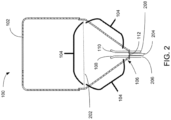
- FIG. 2 is a schematic diagram showing a cross-section view of an example of an apparatus 100 for transferring and mixing inks for printing.
- apparatus 100 includes an intermediate tank 102 that has a mixing area 104 formed by a funnel or inverted conical portion of the tank.
- Mixing area 104 is for mixing new ink and resident ink.
- the top or upper boundary 202 of the mixing area 104 is indicated by a horizontal broken line that extends across the diameter of intermediate tank 102.
- Apparatus 100 includes a new ink supply inlet tube 108 for depositing into intermediate tank 102 the new ink from a connected ink supply container (not shown in FIG. 2 ), and a resident ink supply inlet tube 110 for depositing into intermediate tank 102 the resident ink from a connected printing device (not shown in FIG. 2 ).
- the deposits of the new ink and the resident ink into mixing area 104 are contemporaneous to cause mixing of the new ink and the resident ink
- Apparatus 100 includes an outlet port 112 situated at the bottom 106 of intermediate tank 102. Outlet port 112 is for sending the mixed ink to the connected printing device via a mixed ink outlet tubing 204.
- FIG. 3A is a schematic diagram showing a cross-section view of another example of an apparatus 100 for transferring and mixing inks for printing.
- apparatus 100 includes an intermediate tank 102 that has a mixing area 104 formed by a funnel or inverted conical portion of the tank. Mixing area 104 is for mixing new ink and resident ink.
- Apparatus 100 includes a new ink supply inlet tube 108 for depositing into intermediate tank 102 the new ink from a connected ink supply container (not shown in FIG. 3A ), and a resident ink supply inlet tube 110 for depositing into intermediate tank 102 the resident ink from a connected printing device (not shown in FIG. 3A ).
- Apparatus 100 includes an outlet port 112 situated at the bottom of intermediate tank 102. Outlet port 112 is for sending the mixed ink to the connected printing device via a mixed ink outlet tube 204.
- FIG. 3B is a perspective view of an example an integrated component 300 that can be seated at the bottom of an intermediate tank 102 ( FIG. 3A ).
- integrated component 300 includes all or a portion of new ink supply inlet tube 108, resident ink supply inlet tube 110, and outlet port 112.
- the integrated component may include a plastic or other polymer composition, metal, rubber (e.g., for a gasket or for a seating member), and/or other materials.
- each of new ink supply inlet tube 108 and resident ink supply inlet tube 110 has a first length 380 that is to extend upward from the tank bottom (106 FIG.
- the angled structure allows, with the assistance of a transfer pump to provide sufficient pressure, the new ink and the resident ink to be sprayed upon the interior walls of intermediate tank 102 in mixing area 104.
- new ink supply inlet tube 108 and resident ink supply inlet tube 112 each extend vertically though the bottom of the shaped intermediate tank, with each having a height 302 that is sufficient to extend into mixing area 104 well above the outlet port 112.
- the heights of new ink supply inlet tube 108 and resident ink supply inlet tube 112 are to be tall enough to ensure the new ink and the resident ink will be deposited by new ink supply inlet tube 108 and resident ink supply inlet tube 112 onto the funnel or inverted conical shaped walls of intermediate tank 102 in the mixing area 104.
- the new ink and the resident ink are to be deposited with sufficient force to cause the inks to circulate around, e.g., radially, the interior walls of the funnel or inverted conical shaped mixing area before exiting via outlet port 112.
- the heights of one or both of new ink supply inlet tube 108 and resident ink supply inlet tube 112 are between 5% and 30% of the height 360 of the mixing area 104.
- the height 360 of the mixing area 104 is indicated by a broken line which extends vertically from bottom of intermediate tank 102 to the top upper boundary 362 of the funnel shaped or inverted conical shaped mixing area 104.
- the top or upper boundary 202 of mixing area 104 is indicated by a horizontal broken line that extends across the diameter of intermediate tank 102.
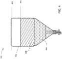
- FIG. 4 is a schematic diagram showing a cross-section view of an example of an apparatus 100 for transferring and mixing inks for printing wherein the intermediate tank 102 is full after a transfer of all ink from an ink supply container.
- “full” means that the ink has reached or exceeded a threshold of liquid volume that has been predetermined to be a maximum desired capacity for intermediate tank 102 (a "full threshold 402).
- the ink in intermediate tank 102 includes a first volume of ink 406 in the mixing area 104 denoted with horizontally hashed lines, and second volume of ink 408 in an area of intermediate tank 102 above mixing area 104, the second volume of ink indicated by diagonal hashed lines.
- full is actually a threshold volume point that is less than having intermediate tank 102 be filled to a point that is the maximum physically possible 404. Overfilling intermediate tank 102 to the point of ink spillage or creating abnormal pressures in intermediate tank 102 would be a highly detrimental event in terms of damage to equipment, lost time, and ruined print jobs. Having the system recognize a "full" threshold be a detected volume that is less than actual physical capacity of intermediate tank 102, then, affords margin for error such that a sensor error is less likely to result in damaged equipment.
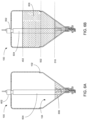
- FIG. 5A is a schematic diagram showing a cross-section view of another example of apparatus 100 for transferring and mixing inks for printing.
- apparatus 100 upon a determination (e.g., receiving data originating from a sensor) that the mixed ink 504 in intermediate tank 102 is at or beneath the ink low threshold level 502, initiates an additional transfer of ink into mixing area 104 from a new or fresh ink supply container.
- the ink low threshold level 502 is a fluid level that is between a tank "full" level (402 FIG. 4 ) and a tank empty/stop operations level (510 FIG. 5B ), and has been predetermined to be an ideal level for initiating a resupply of intermediate tank 102.
- Connecting a new or fresh ink supply container, directly or indirectly, to new ink supply inlet tube 108 (e.g. by connecting to new ink connective tube 206 that connects to new ink supply inlet tube 108) at the time that "low" level 502 is indicated is to allow enough time for the refilling of mixing area 104 without having to stop printing operations. In other words, printing operations do not need to be suspended because at the "low" level 502 there is enough mixed ink in mixing area 104 to sustain printing operations through the refill process assuming the refill operation proceeds at an expected rate. Suspending print operations to enable refilling can be highly detrimental to commercial printing schedules.
- "initiating" transfer may include sending a user message or instruction that a new or fresh ink supply container needs to be moved into proximity of intermediate tank 102, and connected to new ink supply inlet tube 108, e.g., via new ink connective tubing 206.
- "initiating" transfer may include automatically moving a new or fresh ink supply container into proximity of intermediate tank 102, and connecting the new ink supply container to new ink supply inlet tube 108 via new ink connective tubing 206. It should be noted that while in the example of FIG.
- the low threshold level is a level that is the top of funnel or inverted conical-shaped mixing zone 104, in other examples the low threshold level could be a predetermined threshold level this higher than, or lower than, threshold level 502 depicted in FIG. 5A .
- FIG. 5B is a is a schematic diagram showing a cross-section view of an example of an apparatus for transferring and mixing inks for printing, wherein the ink level in the intermediate tank has fallen below the low threshold level (502 FIG. 5A ) to an empty/stop operations level 510, and printing operations are to be shut down.
- the change in ink levels may be due to the printing device having utilized the mixed ink that had resided in mixing areas 104 more before the ink level could be replenished by adding ink from a new ink supply container.
- apparatus 100 upon determining the mixed ink 504 level in intermediate tank 102 is at or beneath the empty/stop operations level 510, apparatus 100 causes an immediate cessation of printing operations.
- printing operations may only resume after there has been a transfer of additional ink from an ink supply container into intermediate tank 102. Should the mixed ink 504 level drop below the output port 112, output port 112 would draw air into the mixed ink output tubing 204 that leads to the printheads of the printing device and serious damage to the printing device, a ruined print job, and delays for repair may result. While in the example of FIG. 5B the empty/stop operations threshold level is a level that is roughly even with the height 302 of new ink supply inlet tube 108 and resident ink supply tube 110, in other examples the stop operations threshold level could be a predetermined threshold level this higher than, or lower than, empty/stop operations threshold level 510 depicted in FIG. 5B .
- ink transfer and mixing apparatus 100 may include a sensor 602 for determining ink levels in the intermediate tank 102.
- sensor 602 may be any sensor type that directs a sense beam 604 towards mixing area 104 to detect the level or volume of ink 606 in the intermediate tank 102.
- sensor 602 may be an ultrasonic level sensor, a radar level transmitter, a guided microwave level transmitter, or any type of level or volume sensor.
- FIG. 6B in view of FIGS.
- sensor 602 may direct a sense beam 604 towards mixing area 104 to detect that ink in intermediate tank is at an ink full threshold 402, an ink low threshold level 502, and/or an empty/stop operations level 510.
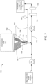
- FIG. 7 is a simple schematic diagram that illustrates an example of a printing system 700 that includes an intermediate tank 102 with a funnel or inverted conical shape mixing area 104 for mixing new ink 702 from an ink supply container 704 and resident ink 706 from a printing device 708.
- printing device 708 may be an inkjet web fed printing device that delivers ink to media utilizing a set of printbars, with each printbar including a set of printheads 710.
- printing device 708 may be any other type of printing device that consumes liquid ink.
- Intermediate tank 102 is connected by tubing to printing device 708 and new ink supply container 704.
- Intermediate tank 102 includes a mixing area 104 formed by an inverted conical shape or a funnel shape for mixing new ink 702 and resident ink 706.
- Intermediate tank 102 includes an outlet port 112 situated at the bottom 106 of tank bottom 102, the outlet port 112 for sending mixed ink 712 to the printheads 710.
- Printing system 700 includes a new ink supply inlet tube 108 connected to intermediate tank 102. New ink supply inlet tube 108 is for streaming into the tank the new ink 702 from the connected ink supply container 704.
- Printing system 700 includes a resident ink supply inlet tube 110 connected to intermediate tank 102 and printing device 708. Resident ink supply inlet tube 110 is for streaming into the tank resident ink 706 from printing device 708.
- FIG. 7 In the example of FIG.
- both the new ink supply inlet tube 108 and resident ink inlet tube have a first length that extends vertically from bottom of the conically shaped tank, and a second length that is angled from vertical, to cause the spraying of new ink 702 and resident ink 706 onto the interior walls of mixing area 104 of tank 102.
- Printing system 700 includes a transfer pump 714 connected to new ink supply inlet tube 108 and situated in line between ink supply container 704 and intermediate tank 102. Transfer pump 714 is to cause the transfer of new ink 702 from ink supply container 704 to intermediate tank 102.
- Printing system 700 includes a pressure pump 716 connected to resident ink supply inlet tube 110 and situated in line between printing device 708 and intermediate tank 102.
- Pressure pump 716 is to cause the transfer of mixed ink 712 from intermediate tank 102 to printing device 708 in order that mixed ink 712 can be ejected by printheads 710.
- pressure sensor 718 is connected to the tubing for connecting outlet port 112, printing device 708, and resident ink supply inlet tube 110.
- Pressure sensor 718 is to measure the pressure at which mixed ink 712 is being provided to the printing device and/or the pressure at which resident ink being sent to mixing area 104 via resident ink supply inlet tube 110.
- printing system 700 includes a filter 720 and a degas unit 722 that are connected by tubing with outlet port 112 and are connected by tubing with printing device 708.
- Filter 720 is for removing contaminants from mixed ink 712 prior to the mixed ink being utilized in a printing operation at printing device 708.
- Degas unit 722 is for removing bubbles in mixed ink 712 prior to the printheads 710 at printing device 708 ejecting mixed ink 712 upon a media.
- FIG. 8 is a flow diagram of implementation of a method for transferring and mixing ink.
- ink is transferred from a supply container into a mixing area of an intermediate tank through a new ink supply inlet tube.
- the mixing area has a funnel shape or an inverted conical shape (block 802).
- Resident ink is transferred from a printing device into the mixing area through a resident ink supply inlet tube.
- the transfers of the new ink and the resident ink into the mixing area are contemporaneous and cause mixing of the new ink and the resident ink (block 804).
- Mixed ink is transferred from the mixing area to the printing device through an outlet port situated at bottom of the intermediate tank (block 804).
- FIGS. 1-8 aid in depicting the architecture, functionality, and operation of various examples.
- FIGS. 1-7 depict various physical and logical components.
- Various components are defined at least in part as programs or programming. Each such component, portion thereof, or various combinations thereof may represent in whole or in part a module, segment, or portion of code that comprises executable instructions to implement any specified logical function(s).
- Each component or various combinations thereof may represent a circuit or a number of interconnected circuits to implement the specified logical function(s). Examples can be realized in a memory resource for use by or in connection with a processing resource.
- a “processing resource” is an instruction execution system such as a computer/processor based system or an ASIC (Application Specific Integrated Circuit) or other system that can fetch or obtain instructions and data from computer-readable media and execute the instructions contained therein.
- a “memory resource” is a non-transitory storage media that can contain, store, or maintain programs and data for use by or in connection with the instruction execution system. The term “non-transitory” is used only to clarify that the term media, as used herein, does not encompass a signal.
- the memory resource can comprise a physical media such as, for example, electronic, magnetic, optical, electromagnetic, or semiconductor media. More specific examples of suitable computer-readable media include, but are not limited to, hard drives, solid state drives, random access memory (RAM), read-only memory (ROM), erasable programmable read-only memory (EPROM), flash drives, and portable compact discs.
- FIG. 8 shows specific orders of execution, the order of execution may differ from that which is depicted.
- the order of execution of two or more blocks or arrows may be scrambled relative to the order shown.
- two or more blocks shown in succession may be executed concurrently or with partial concurrence. Such variations are within the scope of the present disclosure.
Landscapes
- Ink Jet (AREA)
Claims (12)
- Verfahren zum Übertragen und Mischen von Tinte zum Drucken, das umfasst:Übertragen von Tinte von einem Zufuhrbehälter in einen Mischbereich (104) eines Tanks (102) durch ein Zufuhreinlassrohr (108) für neue Tinte, wobei der Mischbereich (104) eine umgekehrt konische Form aufweist;Übertragen vorhandener Tinte von einer Druckvorrichtung (708) in den Mischbereich (104) durch ein Zufuhreinlassrohr (110) für vorhandene Tinte,wobei die Übertragungen der neuen Tinte und der vorhandenen Tinte in den Mischbereich (104) gleichzeitig stattfinden und ein Mischen der neuen Tinte und der vorhandenen Tinte bewirken; undÜbertragen gemischter Tinte von dem Mischbereich (104) zu der Druckvorrichtung (708) durch einen Auslassanschluss (112), der an dem Boden des Tanks (102) gelegen ist.
- Verfahren nach Anspruch 1, wobei die Übertragungen der neuen Tinte und der vorhandenen Tinte in den Mischbereich (104) bei jeweiligen Drücken stattfinden, die ausreichend sind, um zu bewirken, dass die neue Tinte und die vorhandene Tinte entlang einer Innenoberfläche des Mischbereichs (104) radial zirkulieren.
- Verfahren nach Anspruch 1, wobei das Übertragen der neuen Tinte von dem Zufuhrbehälter zu dem Mischbereich (104) ein ununterbrochenes Übertragen eines Gesamtvolumens neuer Tinte in den Zufuhrbehälter einschließt.
- Verfahren nach Anspruch 1, wobei der Tintenzufuhrbehälter ein zweiter Tintenzufuhrbehälter ist und die vorhandene Tinte Tinte einschließt, die von einem ersten Tintenzufuhrbehälter stammt und durch die Druckvorrichtung (708) zirkuliert ist.
- Verfahren nach Anspruch 1, wobei der Zufuhrbehälter ein erster Zufuhrbehälter ist, und das ferner umfasst, bei einer Bestimmung, dass gemischte Tinte in dem Tank (102) unter einen Schwellenpegel (502) gefallen ist, ein Einleiten einer zusätzlichen Übertragung von Tinte von einem zweiten Zufuhrbehälter zu dem Mischbereich (104).
- Verfahren nach Anspruch 1, wobei der Schwellenpegel (502) ein erster Schwellenpegel ist, und das ferner umfasst, bei einer Bestimmung, dass gemischte Tinte in dem Tank (102) unter einen zweiten Schwellenpegel gefallen ist, ein Bewirken, dass Druckvorgänge stoppen.
- Tintenübertragungs- und -mischeinrichtung (100), die umfasst:einen Tank (102), wobei der Tank (102) einen Mischbereich (104), der über einen Trichterabschnitt ausgebildet wird, wobei der Mischbereich (104) zum Mischen von neuer Tinte und vorhandener Tinte dient, und einen Tankboden (106) aufweist;ein Zufuhreinlassrohr (108) für neue Tinte zum Ablagern der neuen Tinte von einem verbundenen Tintenzufuhrbehälter in den Tank (102), wobei das Zufuhreinlassrohr (108) für neue Tinte eine erste Länge eines Einlassrohrs für neue Tinte, die sich von dem Tankboden (106) nach oben erstreckt, und eine zweite Länge eines Einlassrohrs für neue Tinte, die nach außen zu einer Wand des Tanks (102) hin abgewinkelt ist, aufweist;ein Zufuhreinlassrohr (110) für vorhandene Tinte zum Ablagern der vorhandenen Tinte von einer verbundenen Druckvorrichtung (708) in den Tank (102), wobei das Zufuhreinlassrohr (110) für vorhandene Tinte eine erste Länge eines Einlassrohrs für vorhandene Tinte, die sich von dem Tankboden (106) nach oben erstreckt, und eine zweite Länge eines Einlassrohrs für vorhandene Tinte, die nach außen zu einer Wand des Tanks (102) hin abgewinkelt ist, aufweist; undeinen Auslassanschluss (112), der an dem Tankboden (106) zum Befördern der gemischten Tinte zu der Druckvorrichtung (708) gelegen ist.
- Einrichtung (100) nach Anspruch 7, wobei das Zufuhreinlassrohr (108) für neue Tinte, das Zufuhreinlassrohr (110) für vorhandene Tinte und der Auslassanschluss (112) als Teil einer einzigen Komponente, die an dem Tankboden (106) sitzt, angeordnet sind.
- Einrichtung (100) nach Anspruch 7, wobei das Zufuhreinlassrohr (108) für neue Tinte und das Zufuhreinlassrohr (110) für vorhandene Tinte sich jeweils vertikal durch den Tankboden (106) erstrecken und jeweils eine Höhe (302) aufweisen, die zwischen 5 % und 30 % der Höhe (360) des Mischbereichs (104) des Tanks (102) beträgt.
- Einrichtung (100) nach Anspruch 7, die ferner umfassteine Übertragungspumpe (714), die über eine Rohrleitung mit dem Zufuhreinlassrohr (110) für vorhandene Tinte verbunden ist und die über eine Rohrleitung in Verbindung mit einem Tintenzufuhrbehälter sein soll, wobei die Tintenübertragungspumpe (714) eine Übertragung der neuen Tinte von dem Tintenzufuhrbehälter zu dem Tank (102) bewirkt; undeine Druckpumpe (716), die über eine Rohrleitung mit dem Auslassanschluss (112) verbunden ist und über eine Rohrleitung mit der Druckvorrichtung (708) verbunden ist, wobei die Druckpumpe (716) dazu dient, eine Übertragung der gemischten Tinte von dem Tank (102) zu der Druckvorrichtung (708) zu bewirken und dazu dient, eine Übertragung der vorhandenen Tinte von der Druckvorrichtung (708) zu dem Tank (102) zu bewirken.
- Einrichtung (100) nach Anspruch 7, die ferner einen Filter (720) und eine Entgasungseinheit (722) umfasst, die über eine Rohrleitung mit dem Auslassanschluss (112) verbunden sind und die über eine Rohrleitung mit der Druckvorrichtung (708) verbunden sind, wobei der Filter (720) dazu dient, Verunreinigungen von der gemischten Tinte zu entfernen, und die Entgasungseinheit (722) dazu dient, Blasen in der gemischten Tinte zu entfernen, bevor Druckköpfe (710) an der Druckvorrichtung (708) die gemischte Tinte auf ein Substrat ausstoßen.
- Verfahren nach Anspruch 1, wobei jedes des Zufuhreinlassrohrs (108) für neue Tinte und des Zufuhreinlassrohrs (110) für vorhandene Tinte eine erste Länge (380), die sich von dem Tankboden (106) nach oben erstreckt, und eine zweite Länge (382), die nach außen zu einer Wand des Tanks (102) hin abgewinkelt ist, aufweist.
Applications Claiming Priority (1)
| Application Number | Priority Date | Filing Date | Title |
|---|---|---|---|
| PCT/US2019/015898 WO2020159502A1 (en) | 2019-01-30 | 2019-01-30 | Transferring and mixing inks for printing |
Publications (3)
| Publication Number | Publication Date |
|---|---|
| EP3880482A1 EP3880482A1 (de) | 2021-09-22 |
| EP3880482A4 EP3880482A4 (de) | 2022-06-22 |
| EP3880482B1 true EP3880482B1 (de) | 2024-10-02 |
Family
ID=71842371
Family Applications (1)
| Application Number | Title | Priority Date | Filing Date |
|---|---|---|---|
| EP19914055.9A Active EP3880482B1 (de) | 2019-01-30 | 2019-01-30 | Überführen und mischen von farben zum drucken |
Country Status (4)
| Country | Link |
|---|---|
| US (2) | US11453218B2 (de) |
| EP (1) | EP3880482B1 (de) |
| CN (1) | CN113316519B (de) |
| WO (1) | WO2020159502A1 (de) |
Family Cites Families (16)
| Publication number | Priority date | Publication date | Assignee | Title |
|---|---|---|---|---|
| JP2817657B2 (ja) | 1994-08-23 | 1998-10-30 | 富士ゼロックス株式会社 | インク供給装置および記録装置 |
| US6003965A (en) * | 1995-09-01 | 1999-12-21 | Videojet Systems International, Inc. | Ink and solvent container for ink jet printers |
| JP2002370375A (ja) | 2001-06-18 | 2002-12-24 | Canon Inc | インクジェットプリント装置、インクタンクおよびインク供給方法 |
| US20030007040A1 (en) | 2001-07-03 | 2003-01-09 | Eastman Kodak Company | Large volume ink supply system |
| JP5250275B2 (ja) | 2008-02-06 | 2013-07-31 | 株式会社セイコーアイ・インフォテック | インクジェットプリンタのインク供給システム、インクジェットプリンタのインク供給方法、並びにインクジェットプリンタ |
| US8210666B2 (en) * | 2008-07-30 | 2012-07-03 | Sony Corporation | Liquid supplying device, liquid discharging device, and method of controlling liquid discharging device |
| WO2010032984A2 (ko) * | 2008-09-22 | 2010-03-25 | Na Jong Kap | 잉크 점도 조절 장치 |
| AT507445B1 (de) | 2008-10-31 | 2011-09-15 | Durst Phototechnik Digital Technology Gmbh | Tintenversorgungssystem für einen tintenstrahldrucker |
| FR2954216B1 (fr) * | 2009-12-23 | 2013-02-08 | Markem Imaje | Systeme de mesure dans un circuit de fluides d'une imprimante a jet d'encre continu, circuit de fluides associe et bloc destine a mettre en oeuvre un tel systeme de mesure |
| DE102010061001B4 (de) * | 2010-12-03 | 2013-07-04 | OCé PRINTING SYSTEMS GMBH | Tintendrucker mit einem Tintenzwischenbehälter und einem Strömungsrichtungsgeber zum Durchmischen der Tinte |
| US20120169813A1 (en) * | 2010-12-29 | 2012-07-05 | Trevor Gray | Consumable supply item, fluid reservoir and recirculation system for micro-fluid applications |
| US8371684B2 (en) * | 2011-01-31 | 2013-02-12 | Videojet Technologies Inc. | Ink mixing system |
| US9272523B2 (en) * | 2014-04-02 | 2016-03-01 | Memjet Technology Ltd. | Printer configured for optimized printing |
| FR3026050A1 (fr) * | 2014-09-18 | 2016-03-25 | Markem Imaje Holding | Circuit d'encre pour encres pigmentaires |
| EP3212407B1 (de) | 2014-10-30 | 2020-08-05 | Hewlett-Packard Development Company, L.P. | Tintenstrahldrucker mit primären und sekundären tintenbehälter |
| WO2017091406A1 (en) | 2015-11-25 | 2017-06-01 | Videojet Technologies Inc. | Ink quality sensor and a condition monitoring system for an inkjet printer |
-
2019
- 2019-01-30 EP EP19914055.9A patent/EP3880482B1/de active Active
- 2019-01-30 US US17/255,621 patent/US11453218B2/en active Active
- 2019-01-30 CN CN201980089068.2A patent/CN113316519B/zh active Active
- 2019-01-30 WO PCT/US2019/015898 patent/WO2020159502A1/en not_active Ceased
-
2022
- 2022-08-15 US US17/819,755 patent/US11685160B2/en active Active
Also Published As
| Publication number | Publication date |
|---|---|
| EP3880482A4 (de) | 2022-06-22 |
| US20220388310A1 (en) | 2022-12-08 |
| US20210347176A1 (en) | 2021-11-11 |
| US11685160B2 (en) | 2023-06-27 |
| US11453218B2 (en) | 2022-09-27 |
| WO2020159502A1 (en) | 2020-08-06 |
| EP3880482A1 (de) | 2021-09-22 |
| CN113316519B (zh) | 2022-10-14 |
| CN113316519A (zh) | 2021-08-27 |
Similar Documents
| Publication | Publication Date | Title |
|---|---|---|
| JP6099306B2 (ja) | 記録媒体に印刷するためのインクプリンタ | |
| CN101310988B (zh) | 喷墨打印机的气泡去除装置和利用该装置去除气泡的方法 | |
| CN108454233A (zh) | 喷墨打印设备 | |
| US11400726B2 (en) | Printing apparatus and printing system | |
| CN100337829C (zh) | 喷墨打印装置和用于喷墨打印装置的打印头 | |
| JP2023526391A (ja) | 固体粒子高配合インクを取り扱うインクジェットインクシステム | |
| CN101883682B (zh) | 图像形成设备和泡沫涂布装置 | |
| US9085167B2 (en) | Arrangement to supply a print head unit having at least one print head with ink in an ink printing apparatus | |
| EP3689617A1 (de) | Rührvorrichtung für tinte und druckeinrichtung | |
| CN109130523B (zh) | 一种墨水循环方法及其系统 | |
| US11685160B2 (en) | Transferring and mixing inks for printing | |
| KR101113399B1 (ko) | 잉크젯 헤드 어셈블리 | |
| JP2022116363A (ja) | 液体吐出装置およびその制御方法 | |
| CN107116899A (zh) | 图像形成装置、图像形成方法 | |
| JP2018176666A (ja) | インクジェット記録装置、および液体供給装置、並びに液体供給方法 | |
| JP2010115900A (ja) | 画像形成装置、空吐出制御方法及びプログラム | |
| JP6805550B2 (ja) | 画像形成装置及びプログラム | |
| KR101916690B1 (ko) | 오버플로어 예방이 가능한 냉온 제어 잉크 순환시스템 | |
| US11975538B2 (en) | Liquid ejecting apparatus and method of controlling liquid ejecting apparatus | |
| JP7696267B2 (ja) | 印刷装置およびインク供給方法 | |
| EP4375073A1 (de) | Tintenliefergerät | |
| US20240075749A1 (en) | Ink supply system and ink supply method for digital printing | |
| KR200364777Y1 (ko) | 기포제거수단을 갖는 잉크젯 프린터용 잉크카트리지 | |
| JP5699647B2 (ja) | 画像形成装置及び処理液塗布装置 | |
| JP2025145937A (ja) | インク供給装置 |
Legal Events
| Date | Code | Title | Description |
|---|---|---|---|
| STAA | Information on the status of an ep patent application or granted ep patent |
Free format text: STATUS: THE INTERNATIONAL PUBLICATION HAS BEEN MADE |
|
| PUAI | Public reference made under article 153(3) epc to a published international application that has entered the european phase |
Free format text: ORIGINAL CODE: 0009012 |
|
| STAA | Information on the status of an ep patent application or granted ep patent |
Free format text: STATUS: REQUEST FOR EXAMINATION WAS MADE |
|
| 17P | Request for examination filed |
Effective date: 20210617 |
|
| AK | Designated contracting states |
Kind code of ref document: A1 Designated state(s): AL AT BE BG CH CY CZ DE DK EE ES FI FR GB GR HR HU IE IS IT LI LT LU LV MC MK MT NL NO PL PT RO RS SE SI SK SM TR |
|
| DAV | Request for validation of the european patent (deleted) | ||
| DAX | Request for extension of the european patent (deleted) | ||
| A4 | Supplementary search report drawn up and despatched |
Effective date: 20220524 |
|
| RIC1 | Information provided on ipc code assigned before grant |
Ipc: B41J 2/18 20060101ALI20220518BHEP Ipc: B41J 2/17 20060101ALI20220518BHEP Ipc: B41J 2/175 20060101AFI20220518BHEP |
|
| GRAP | Despatch of communication of intention to grant a patent |
Free format text: ORIGINAL CODE: EPIDOSNIGR1 |
|
| STAA | Information on the status of an ep patent application or granted ep patent |
Free format text: STATUS: GRANT OF PATENT IS INTENDED |
|
| INTG | Intention to grant announced |
Effective date: 20240701 |
|
| GRAS | Grant fee paid |
Free format text: ORIGINAL CODE: EPIDOSNIGR3 |
|
| GRAA | (expected) grant |
Free format text: ORIGINAL CODE: 0009210 |
|
| STAA | Information on the status of an ep patent application or granted ep patent |
Free format text: STATUS: THE PATENT HAS BEEN GRANTED |
|
| AK | Designated contracting states |
Kind code of ref document: B1 Designated state(s): AL AT BE BG CH CY CZ DE DK EE ES FI FR GB GR HR HU IE IS IT LI LT LU LV MC MK MT NL NO PL PT RO RS SE SI SK SM TR |
|
| REG | Reference to a national code |
Ref country code: GB Ref legal event code: FG4D |
|
| REG | Reference to a national code |
Ref country code: CH Ref legal event code: EP |
|
| REG | Reference to a national code |
Ref country code: DE Ref legal event code: R096 Ref document number: 602019059883 Country of ref document: DE |
|
| REG | Reference to a national code |
Ref country code: IE Ref legal event code: FG4D |
|
| REG | Reference to a national code |
Ref country code: LT Ref legal event code: MG9D |
|
| REG | Reference to a national code |
Ref country code: NL Ref legal event code: MP Effective date: 20241002 |
|
| REG | Reference to a national code |
Ref country code: AT Ref legal event code: MK05 Ref document number: 1728205 Country of ref document: AT Kind code of ref document: T Effective date: 20241002 |
|
| PG25 | Lapsed in a contracting state [announced via postgrant information from national office to epo] |
Ref country code: NL Free format text: LAPSE BECAUSE OF FAILURE TO SUBMIT A TRANSLATION OF THE DESCRIPTION OR TO PAY THE FEE WITHIN THE PRESCRIBED TIME-LIMIT Effective date: 20241002 |
|
| PG25 | Lapsed in a contracting state [announced via postgrant information from national office to epo] |
Ref country code: NL Free format text: LAPSE BECAUSE OF FAILURE TO SUBMIT A TRANSLATION OF THE DESCRIPTION OR TO PAY THE FEE WITHIN THE PRESCRIBED TIME-LIMIT Effective date: 20241002 |
|
| PG25 | Lapsed in a contracting state [announced via postgrant information from national office to epo] |
Ref country code: HR Free format text: LAPSE BECAUSE OF FAILURE TO SUBMIT A TRANSLATION OF THE DESCRIPTION OR TO PAY THE FEE WITHIN THE PRESCRIBED TIME-LIMIT Effective date: 20241002 Ref country code: PT Free format text: LAPSE BECAUSE OF FAILURE TO SUBMIT A TRANSLATION OF THE DESCRIPTION OR TO PAY THE FEE WITHIN THE PRESCRIBED TIME-LIMIT Effective date: 20250203 Ref country code: IS Free format text: LAPSE BECAUSE OF FAILURE TO SUBMIT A TRANSLATION OF THE DESCRIPTION OR TO PAY THE FEE WITHIN THE PRESCRIBED TIME-LIMIT Effective date: 20250202 |
|
| PG25 | Lapsed in a contracting state [announced via postgrant information from national office to epo] |
Ref country code: FI Free format text: LAPSE BECAUSE OF FAILURE TO SUBMIT A TRANSLATION OF THE DESCRIPTION OR TO PAY THE FEE WITHIN THE PRESCRIBED TIME-LIMIT Effective date: 20241002 |
|
| PG25 | Lapsed in a contracting state [announced via postgrant information from national office to epo] |
Ref country code: BG Free format text: LAPSE BECAUSE OF FAILURE TO SUBMIT A TRANSLATION OF THE DESCRIPTION OR TO PAY THE FEE WITHIN THE PRESCRIBED TIME-LIMIT Effective date: 20241002 |
|
| PG25 | Lapsed in a contracting state [announced via postgrant information from national office to epo] |
Ref country code: ES Free format text: LAPSE BECAUSE OF FAILURE TO SUBMIT A TRANSLATION OF THE DESCRIPTION OR TO PAY THE FEE WITHIN THE PRESCRIBED TIME-LIMIT Effective date: 20241002 |
|
| PG25 | Lapsed in a contracting state [announced via postgrant information from national office to epo] |
Ref country code: NO Free format text: LAPSE BECAUSE OF FAILURE TO SUBMIT A TRANSLATION OF THE DESCRIPTION OR TO PAY THE FEE WITHIN THE PRESCRIBED TIME-LIMIT Effective date: 20250102 |
|
| PG25 | Lapsed in a contracting state [announced via postgrant information from national office to epo] |
Ref country code: AT Free format text: LAPSE BECAUSE OF FAILURE TO SUBMIT A TRANSLATION OF THE DESCRIPTION OR TO PAY THE FEE WITHIN THE PRESCRIBED TIME-LIMIT Effective date: 20241002 Ref country code: GR Free format text: LAPSE BECAUSE OF FAILURE TO SUBMIT A TRANSLATION OF THE DESCRIPTION OR TO PAY THE FEE WITHIN THE PRESCRIBED TIME-LIMIT Effective date: 20250103 Ref country code: LV Free format text: LAPSE BECAUSE OF FAILURE TO SUBMIT A TRANSLATION OF THE DESCRIPTION OR TO PAY THE FEE WITHIN THE PRESCRIBED TIME-LIMIT Effective date: 20241002 |
|
| PG25 | Lapsed in a contracting state [announced via postgrant information from national office to epo] |
Ref country code: CZ Free format text: LAPSE BECAUSE OF FAILURE TO SUBMIT A TRANSLATION OF THE DESCRIPTION OR TO PAY THE FEE WITHIN THE PRESCRIBED TIME-LIMIT Effective date: 20241002 Ref country code: PL Free format text: LAPSE BECAUSE OF FAILURE TO SUBMIT A TRANSLATION OF THE DESCRIPTION OR TO PAY THE FEE WITHIN THE PRESCRIBED TIME-LIMIT Effective date: 20241002 |
|
| PG25 | Lapsed in a contracting state [announced via postgrant information from national office to epo] |
Ref country code: RS Free format text: LAPSE BECAUSE OF FAILURE TO SUBMIT A TRANSLATION OF THE DESCRIPTION OR TO PAY THE FEE WITHIN THE PRESCRIBED TIME-LIMIT Effective date: 20250102 |
|
| PG25 | Lapsed in a contracting state [announced via postgrant information from national office to epo] |
Ref country code: SM Free format text: LAPSE BECAUSE OF FAILURE TO SUBMIT A TRANSLATION OF THE DESCRIPTION OR TO PAY THE FEE WITHIN THE PRESCRIBED TIME-LIMIT Effective date: 20241002 |
|
| REG | Reference to a national code |
Ref country code: DE Ref legal event code: R097 Ref document number: 602019059883 Country of ref document: DE |
|
| PG25 | Lapsed in a contracting state [announced via postgrant information from national office to epo] |
Ref country code: DK Free format text: LAPSE BECAUSE OF FAILURE TO SUBMIT A TRANSLATION OF THE DESCRIPTION OR TO PAY THE FEE WITHIN THE PRESCRIBED TIME-LIMIT Effective date: 20241002 |
|
| PG25 | Lapsed in a contracting state [announced via postgrant information from national office to epo] |
Ref country code: EE Free format text: LAPSE BECAUSE OF FAILURE TO SUBMIT A TRANSLATION OF THE DESCRIPTION OR TO PAY THE FEE WITHIN THE PRESCRIBED TIME-LIMIT Effective date: 20241002 |
|
| PG25 | Lapsed in a contracting state [announced via postgrant information from national office to epo] |
Ref country code: RO Free format text: LAPSE BECAUSE OF FAILURE TO SUBMIT A TRANSLATION OF THE DESCRIPTION OR TO PAY THE FEE WITHIN THE PRESCRIBED TIME-LIMIT Effective date: 20241002 |
|
| PG25 | Lapsed in a contracting state [announced via postgrant information from national office to epo] |
Ref country code: SK Free format text: LAPSE BECAUSE OF FAILURE TO SUBMIT A TRANSLATION OF THE DESCRIPTION OR TO PAY THE FEE WITHIN THE PRESCRIBED TIME-LIMIT Effective date: 20241002 |
|
| PG25 | Lapsed in a contracting state [announced via postgrant information from national office to epo] |
Ref country code: IT Free format text: LAPSE BECAUSE OF FAILURE TO SUBMIT A TRANSLATION OF THE DESCRIPTION OR TO PAY THE FEE WITHIN THE PRESCRIBED TIME-LIMIT Effective date: 20241002 |
|
| PLBE | No opposition filed within time limit |
Free format text: ORIGINAL CODE: 0009261 |
|
| STAA | Information on the status of an ep patent application or granted ep patent |
Free format text: STATUS: NO OPPOSITION FILED WITHIN TIME LIMIT |
|
| REG | Reference to a national code |
Ref country code: CH Ref legal event code: PL |
|
| PG25 | Lapsed in a contracting state [announced via postgrant information from national office to epo] |
Ref country code: SE Free format text: LAPSE BECAUSE OF FAILURE TO SUBMIT A TRANSLATION OF THE DESCRIPTION OR TO PAY THE FEE WITHIN THE PRESCRIBED TIME-LIMIT Effective date: 20241002 |
|
| 26N | No opposition filed |
Effective date: 20250703 |
|
| PG25 | Lapsed in a contracting state [announced via postgrant information from national office to epo] |
Ref country code: LU Free format text: LAPSE BECAUSE OF NON-PAYMENT OF DUE FEES Effective date: 20250130 Ref country code: MC Free format text: LAPSE BECAUSE OF FAILURE TO SUBMIT A TRANSLATION OF THE DESCRIPTION OR TO PAY THE FEE WITHIN THE PRESCRIBED TIME-LIMIT Effective date: 20241002 |
|
| GBPC | Gb: european patent ceased through non-payment of renewal fee |
Effective date: 20250130 |
|
| PG25 | Lapsed in a contracting state [announced via postgrant information from national office to epo] |
Ref country code: BE Free format text: LAPSE BECAUSE OF NON-PAYMENT OF DUE FEES Effective date: 20250131 Ref country code: GB Free format text: LAPSE BECAUSE OF NON-PAYMENT OF DUE FEES Effective date: 20250130 |
|
| PG25 | Lapsed in a contracting state [announced via postgrant information from national office to epo] |
Ref country code: FR Free format text: LAPSE BECAUSE OF NON-PAYMENT OF DUE FEES Effective date: 20250131 |
|
| PG25 | Lapsed in a contracting state [announced via postgrant information from national office to epo] |
Ref country code: CH Free format text: LAPSE BECAUSE OF NON-PAYMENT OF DUE FEES Effective date: 20250131 |
|
| REG | Reference to a national code |
Ref country code: BE Ref legal event code: MM Effective date: 20250131 |
|
| PG25 | Lapsed in a contracting state [announced via postgrant information from national office to epo] |
Ref country code: IE Free format text: LAPSE BECAUSE OF NON-PAYMENT OF DUE FEES Effective date: 20250130 |
|
| PGFP | Annual fee paid to national office [announced via postgrant information from national office to epo] |
Ref country code: DE Payment date: 20251217 Year of fee payment: 8 |