EP3880401B1 - Verbindungsanordnung für eine handgeführte werkzeugmaschine und handgeführte werkzeugmaschine - Google Patents
Verbindungsanordnung für eine handgeführte werkzeugmaschine und handgeführte werkzeugmaschine Download PDFInfo
- Publication number
- EP3880401B1 EP3880401B1 EP20751502.4A EP20751502A EP3880401B1 EP 3880401 B1 EP3880401 B1 EP 3880401B1 EP 20751502 A EP20751502 A EP 20751502A EP 3880401 B1 EP3880401 B1 EP 3880401B1
- Authority
- EP
- European Patent Office
- Prior art keywords
- connection
- section
- extension piece
- sections
- clamping element
- Prior art date
- Legal status (The legal status is an assumption and is not a legal conclusion. Google has not performed a legal analysis and makes no representation as to the accuracy of the status listed.)
- Active
Links
Images








Classifications
-
- B—PERFORMING OPERATIONS; TRANSPORTING
- B24—GRINDING; POLISHING
- B24B—MACHINES, DEVICES, OR PROCESSES FOR GRINDING OR POLISHING; DRESSING OR CONDITIONING OF ABRADING SURFACES; FEEDING OF GRINDING, POLISHING, OR LAPPING AGENTS
- B24B23/00—Portable grinding machines, e.g. hand-guided; Accessories therefor
- B24B23/02—Portable grinding machines, e.g. hand-guided; Accessories therefor with rotating grinding tools; Accessories therefor
-
- B—PERFORMING OPERATIONS; TRANSPORTING
- B25—HAND TOOLS; PORTABLE POWER-DRIVEN TOOLS; MANIPULATORS
- B25F—COMBINATION OR MULTI-PURPOSE TOOLS NOT OTHERWISE PROVIDED FOR; DETAILS OR COMPONENTS OF PORTABLE POWER-DRIVEN TOOLS NOT PARTICULARLY RELATED TO THE OPERATIONS PERFORMED AND NOT OTHERWISE PROVIDED FOR
- B25F5/00—Details or components of portable power-driven tools not particularly related to the operations performed and not otherwise provided for
- B25F5/02—Construction of casings, bodies or handles
-
- B—PERFORMING OPERATIONS; TRANSPORTING
- B24—GRINDING; POLISHING
- B24B—MACHINES, DEVICES, OR PROCESSES FOR GRINDING OR POLISHING; DRESSING OR CONDITIONING OF ABRADING SURFACES; FEEDING OF GRINDING, POLISHING, OR LAPPING AGENTS
- B24B7/00—Machines or devices designed for grinding plane surfaces on work, including polishing plane glass surfaces; Accessories therefor
- B24B7/10—Single-purpose machines or devices
- B24B7/18—Single-purpose machines or devices for grinding floorings, walls, ceilings or the like
- B24B7/182—Single-purpose machines or devices for grinding floorings, walls, ceilings or the like for walls and ceilings
- B24B7/184—Single-purpose machines or devices for grinding floorings, walls, ceilings or the like for walls and ceilings pole sanders
-
- F—MECHANICAL ENGINEERING; LIGHTING; HEATING; WEAPONS; BLASTING
- F16—ENGINEERING ELEMENTS AND UNITS; GENERAL MEASURES FOR PRODUCING AND MAINTAINING EFFECTIVE FUNCTIONING OF MACHINES OR INSTALLATIONS; THERMAL INSULATION IN GENERAL
- F16L—PIPES; JOINTS OR FITTINGS FOR PIPES; SUPPORTS FOR PIPES, CABLES OR PROTECTIVE TUBING; MEANS FOR THERMAL INSULATION IN GENERAL
- F16L33/00—Arrangements for connecting hoses to rigid members; Rigid hose-connectors, i.e. single members engaging both hoses
-
- H—ELECTRICITY
- H01—ELECTRIC ELEMENTS
- H01R—ELECTRICALLY-CONDUCTIVE CONNECTIONS; STRUCTURAL ASSOCIATIONS OF A PLURALITY OF MUTUALLY-INSULATED ELECTRICAL CONNECTING ELEMENTS; COUPLING DEVICES; CURRENT COLLECTORS
- H01R13/00—Details of coupling devices of the kinds covered by groups H01R12/70 or H01R24/00 - H01R33/00
- H01R13/62—Means for facilitating engagement or disengagement of coupling parts or for holding them in engagement
- H01R13/639—Additional means for holding or locking coupling parts together, after engagement, e.g. separate keylock, retainer strap
Definitions
- the invention relates to a connection arrangement having the features of the preamble of claim 1.
- the invention also relates to a machine tool having the features of the independent claim.
- the invention relates to an extension piece with the features of the preamble of claim 20.
- a corresponding connection arrangement and a corresponding extension piece are from EP 2 954 977 A1 known.
- Machine tools are known from the prior art, for example from the applicant DE 10 2007 012 394 A1 .
- a hand-held machine tool described with a handle bar which has a plurality of handle bar parts which can be connected to one another by means of a clamping device. This means that the length of the handlebar can be changed to adapt the machine to the job and the handlebar can be dismantled for transport purposes. This favors the handling of the machine tool.
- the invention is based on the object of facilitating the handling of a hand-held machine tool with simple structural means, in particular its assembly and disassembly.
- connection arrangement with the features of claim 1.
- the connection arrangement is characterized in that an electrical plug connector, a mechanical tensioning element and a connection opening to a flow channel formed in the respective connection part are provided in this way within the respective (inner) cross section are that when plugging the Connecting sections the clamping elements engage behind each other and the connectors are connected to each other (electrical plug connection) and / or the connection openings are connected to each other (flow connection).
- connection sections mechanical clamping connection, electrical plug connection and/or flow connection between the flow channels
- the arrangement of the plug connector, the tensioning element and the connection opening within the cross section of the relevant connection section contributes to a compact design of the connection arrangement, the interfaces mentioned being protected from environmental influences such as dust, dirt or the like.
- connection arrangement can be, for example, a hand-held machine tool.
- connection arrangement can be a connection line, for example a hose or a pipe.
- the connecting parts can have a pipe section, for example, with a connecting section being formed at one end or at both ends of the pipe section.
- the further machine module can be a handle part.
- the handle part can have display elements and/or operating elements for monitoring or operating the machine tool.
- the (inner) cross section of the connecting parts can be, for example, an interior space.
- connection arrangement can be easily assembled or disassembled.
- connection arrangement can be assembled for use of the machine tool and dismantled for transport or storage.
- the tensioning element can be arranged essentially centrally within the cross section. This contributes to a (relative to the circumference) even bracing of the connecting parts. "Substantially in the middle” can be understood to mean that the clamping element is arranged in the middle 1 to 30 percent of the inner cross section (based on the cross sectional area), so to speak approximately halfway up the cross section of the connecting section.
- the plug connector can expediently be arranged on one side of the tensioning element and the connection opening of the flow channel can be arranged on the side of the tensioning element facing away from the plug connector. This contributes to a space-saving and symmetrical arrangement of the interfaces in the connection section.
- the clamping element can be arranged between the plug connector and the connection opening.
- the tensioning element can be arranged at or on the central longitudinal axis of the connection part in question and the plug connector and the connection opening can be arranged laterally to the central longitudinal axis, in particular on opposite sides, preferably diametrically.
- the connecting sections can each have a one-part or multi-part casing, which encloses the respective connecting part in sections. This can be used to protect ends of the connecting parts, for example ends of the tube sections of the connecting parts.
- the casing can, for example, be designed in the form of a sleeve.
- the casing can be formed separately in relation to the connecting part or its pipe section or can coincide with the connecting part or its pipe section, e.g. by designing the connecting part as a hybrid component (casing is applied directly to the connecting part or its pipe section).
- one of the connecting sections (connecting section of a first connecting part), in particular on its casing, can have a collar projecting parallel to the longitudinal axis, with which this connecting section encompasses the opposite connecting section (connecting section of the other connecting part) when plugged together.
- the interfaces of the connecting sections can be aligned with one another.
- the collar helps protect the interfaces of the connecting sections from the environment.
- the collar is preferably designed to run all the way around.
- the collar can expediently have an outwardly widening, in particular conically designed, inner surface and the opposite connecting section can, in particular on its casing, have an outwardly tapering, in particular conically tapering, outer surface. This makes it easier to plug the connecting sections together, since the respective interfaces of the connecting sections to be plugged together (plug connector, clamping element and connection opening) are aligned with one another.
- the connecting sections in particular on their casing, can have a bearing section covering the end face of the respective connecting part, the bearing sections coming into contact with one another when the connecting sections are plugged together.
- pipe sections of the connecting parts can be prevented from directly resting on one another. Wear is reduced to a minimum.
- the connecting section which is encompassed by the opposite connecting section when plugged together, can have a radially protruding shoulder at its end (rear end) facing away from the free end of the respective connecting part.
- This can reduce the risk of ingress of foreign bodies.
- plugging together connecting parts in the direction of insertion can be limited by the shoulder.
- the shoulder itself can have a triangular or trapezoidal cross-section. In this way, a gradual transition can be created between the connecting section and the connecting part or its pipe section. This favors the ergonomics.
- the plug connectors can expediently be designed as multi-pole plug connectors, each with at least two poles (two-pole or multi-pole design). This enables the transmission of electricity (energy supply) and signals. For example, a 7-pole or 7-wire design of the connector is conceivable.
- the plug connector, the tensioning element and/or the connection opening can be arranged flush or offset inwards relative to the end face of the connecting section. In other words, these elements do not protrude from the relevant connecting section at the front. This offers a certain protection from environmental influences for the interfaces. In addition, you can hereby reduce the risk of injury to the user. Wear and tear on the interfaces can also be kept to a minimum.
- At least one of the connectors can be mounted on the respective connection section or on the respective connection part by means of an elastic element, in particular in such a way that the connector can be moved relative to the connection section or to the connection part.
- the connectors thus have a certain amount of play so that the connecting parts can be plugged together more easily.
- the connector can be reset into a, preferably central, initial position by the elastic element. This creates a defined starting position. If the connector rotates off-centre, the return element can be used to return it to its initial position.
- one or more dust removal openings can be formed in the plug connector, in particular adjacent to its plug contacts. This reduces the risk of dust deposits impairing the function of the electrical connectors.
- the dust discharge openings can be flow-connected by means of a flow connection to the flow duct (suction duct) formed in the connection part in question.
- the plug connectors of the connecting sections of a first of the connecting parts and of the second connecting part can be designed to be partially or fully complementary to one another. This means that they can be plugged together (partially or fully complementary configuration of the plug connectors).
- a plug connector of a connecting section can be designed as a plug and the plug connector of a second connecting section can be designed as a socket.
- the connecting parts can each have a wall that extends parallel to or along their longitudinal axis, which divides the cross section of the connecting parts into separate sections, with the flow channel (suction channel) being arranged in a first section and the plug connector and the clamping element each are arranged in another section.
- the plug connector and the tensioning element are separated from the flow channel and are not adversely affected, for example, by removed grinding dust.
- an actuating device can be arranged on at least one of the connecting sections, which is coupled by means of a clamping device to the clamping element arranged on this connecting section, so that the connecting parts can be braced against one another by actuating the actuating device when the clamping elements are engaged.
- the actuator can be be a (manually operable) clamping lever or an (electrically or electronically controllable) actuator.
- a further connecting part can be provided, which has a connecting section at both ends, so that the further connecting part can be inserted as an extension piece between the two connecting parts and, in particular, detachably connected to them.
- the length of the connection arrangement or the machine tool can thus be adjusted if required.
- the clamping elements can be designed as a clamping element on a connecting section, with the clamping element interacting with a clamping device and/or actuating device arranged on this connecting section.
- the clamping element can be designed as a clamping claw.
- the clamping element can be designed as a counter-element which can engage with the clamping element (clamping claw).
- the counter-element can be a hook-shaped element or a hook.
- the object mentioned at the outset is also achieved by a preferably hand-held machine tool having the features of the independent claim.
- the machine tool has a machining head, a further machine module and a connection arrangement for connection of the processing head and the machine module as described above.
- the hand-held power tool can be a surface treatment machine, for example a long-neck grinder.
- the processing head can, for example, be designed as a grinding head.
- the further machine module can be a handle part, for example.
- connection arrangement With regard to the advantages that can be achieved with the machine tool, reference is made to the relevant statements on the connection arrangement.
- the measures described in connection with the connection arrangement can serve to further refine the machine tool.
- extension piece for a connection arrangement having the features of the independent claim.
- the extension piece constitutes a further extension part for a connection arrangement as described above.
- the extension piece has a connecting section at both ends, so that the extension piece can be inserted between the two connecting parts and connected to them for the purpose of lengthening.
- the extension piece for a connection arrangement for connecting a machining head and a further machine module can, preferably hand-held, machine tool.
- the extension piece has a connecting section at both ends, via which the extension piece can be connected to a connecting part of the connecting arrangement, the connecting sections of the extension piece each delimiting an inner cross section (e.g. interior space) to the outside.
- the extension piece is characterized in that an electrical plug connector, a mechanical tensioning element and a connection opening to a flow channel formed in the extension piece are provided within the respective cross section. In this way, the extension piece, as a (further) connecting part, can be connected to a connecting part just as advantageously as the connecting parts of the connecting arrangement described above.
- the electrical plug connector, the mechanical tensioning element and the connection opening can be provided in such a way that when a connection section of the extension piece is plugged into a connection part of the connection arrangement, the tensioning elements engage behind one another and the plug connectors and/or the connection openings are connected to one another. This promotes the ability to connect the extension piece to other connecting parts.
- the connecting sections of the extension piece can be designed to be complementary (partially complementary or fully complementary) to one another. With others Words could be plugged together the two connecting portions of the extension piece. In this way, the extension piece can easily be inserted between the other connecting parts of the connecting arrangement. It is also conceivable for several extension pieces to be plugged together in order to lengthen the connection arrangement.
- the tensioning element can be arranged essentially centrally within the cross section. This contributes to a (relative to the circumference) uniform bracing of the extension piece with other connecting parts. "Substantially in the middle” can be understood to mean that the clamping element is arranged in the middle 1 to 30 percent of the inner cross section (based on the cross sectional area), so to speak approximately halfway up the cross section of the connecting section.
- the plug connector can expediently be arranged on one side of the tensioning element and the connection opening of the flow channel can be arranged on the side of the tensioning element facing away from the plug connector. This contributes to a space-saving and symmetrical arrangement of the interfaces in the connection section.
- the clamping element can be arranged between the plug connector and the connection opening.
- the clamping element can be arranged at or on the central longitudinal axis of the extension piece and the plug connector and the connection opening can be arranged laterally to the central longitudinal axis, in particular on sides that are preferably diametrically opposite one another.
- the plug connectors can expediently be designed as multi-pole plug connectors, each with at least two poles (two-pole or multi-pole design). This enables the transmission of electricity (energy supply) and signals. For example, a 7-pole or 7-wire design of the connector is conceivable.
- the connectors arranged at both ends of the extension piece are electrically connected to one another by means of electrical or electronic lines. Thus, power and/or control signals can be transmitted through the extension piece by means of the electrical plug connectors.
- the plug connector, the tensioning element and/or the connection opening can be arranged flush or offset inwards relative to the end face of the connecting section. In other words, these elements do not protrude from the relevant connecting section at the front. This offers a certain protection from environmental influences for the interfaces. In addition, this reduces the risk of injury for the user. Wear and tear on the interfaces can also be kept to a minimum.
- an actuating device can be arranged on one of the connecting sections, which is coupled by means of a clamping device to the clamping element arranged on this connecting section, so that the extension piece is in engagement with a further connecting part Clamping elements can be braced against one another by actuation of the actuating device.
- the actuating device can be a (manually actuatable) clamping lever or an (electrically or electronically controllable) actuator.
- the extension piece can each have a wall that extends parallel to or along the longitudinal axis, which divides the cross section of the extension piece into separate sections, with the flow channel being arranged in a first section and the plug connector and the tensioning element (both connecting sections of the Extension piece) are each arranged in a further section.
- the plug connector and the tensioning element are separated from the flow channel and are not adversely affected, for example, by removed grinding dust.
- connection with the connection arrangement can serve to further develop the connection sections of the extension piece.
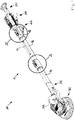
- FIG 1 12 shows a hand-held machine tool, which is denoted overall by the reference numeral 200 (hereinafter "machine tool”).
- the machine tool 200 is embodied here, for example, as a surface treatment machine 200 in the form of a long-neck grinder.
- the machine tool 200 has a machining head 202 in the form of a grinding head 202 .
- the machine tool 200 has a further machine module 204 in the form of a handle part 204 .
- Machine tool 200 also has a connection arrangement 10 for connecting grinding head 202 and handle part 204.
- a hose section 206 is arranged on the grinding head 202 and is fluidically connected at one end to a suction point (not shown) located on the grinding head 202 .
- the hose section 206 is flow-connected at the other end to a hose outlet 208 arranged on the handle part 204, specifically by means of the connection arrangement 10.
- a hose e.g. suction hose
- grinding dust produced on the grinding head 202 can be sucked off at the suction point and discharged via the hose section 206 , the connection arrangement 10 (flow channel or suction channel) and the hose outlet 208 .
- the handle part 204 can have a handle section 210 on which the handle part 204 can be grasped or gripped by hand by a user.
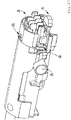
- the connector assembly 10 may include a connector 14 and another connector 18 that can be connected and disconnected from each other (see FIG figure 1 ).
- the connecting parts 14, 18 can be releasably connected to one another.
- the connecting part 18 is formed on the handle part 204 and has a connecting section which corresponds to the connecting section 22 described below (see FIG. 3f.).
- the handle part 204 or its connecting section can be made of plastic, for example.
- the connecting part 14 has at one end a connecting section 20 described below (cf. FIG. 3f.), which is plugged together with the connecting section (without reference number) formed on the handle part 204 can be. At the other end, the connecting part 14 is connected to a connection piece 212 which carries the grinding head 202 .
- connection arrangement 10 can have at least one further connection part 16, which can be inserted between the two other connection parts 14, 18 as an extension piece 16 (see FIG figure 2 ).
- extension piece 16 has a connecting section 20 at one end and a connecting section 22 at the other end, as will be described further below.
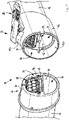
- connection assembly 10 is described in more detail below with reference to the connector portion 20 of the connector 14 and the connector portion 22 of the connector 16 (see marking "A" in figure 2 and Figure 3f.).
- a corresponding connection arrangement 10 is located between the connection part 14 and the connection part 18 or between the connection part 16 and the connection part 18 (cf. marking "A'", only in figure 2 indicated).
- the connecting arrangement 10 forms a connecting line, for example a connecting tube.
- the connecting parts 14, 16 each have a tube section, for example a section of an aluminum tube, on which a respective connecting section 20, 22 is formed.
- connection arrangement 10 serves to connect the sanding head 202 and the handle part 204 of the hand-held power tool 200 in the form of a long-neck sander.
- the connection arrangement 10 has (at least) two connection parts 14, 16 following one another along a longitudinal axis 12 (cf. FIG. 3f.).
- the connecting parts 14, 16 can be releasably connected to one another.
- the connecting part 14 has a connecting section 20 .
- the connecting part 16 has a connecting section 22 .
- the connecting parts 14, 16 can be connected to one another via the connecting sections 20, 22, namely by plugging the connecting sections 20, 22 together.
- the connecting sections 20, 22 each delimit an inner cross section 24, 26 to the outside (see, among figure 5 and 6 ).
- the connecting parts 14, 16 each have three different interfaces, which are each arranged in the inner cross section 24, 26 or in the interior space 24, 26 of the relevant connecting section 20, 22.
- the interfaces are an electrical plug connection, a mechanical clamping connection and a flow connection.
- the clamping connection is spatially arranged between the plug connection and the flow connection and is located approximately in the center of the connection sections.
- the connecting part 14 has an electrical connector 28 in the inner cross-section 24, which forms a component of the electrical connector.
- the plug connector 28 can, for example, be designed as a socket (female part).
- the connecting part 14 has a clamping element in the form of a counter-element 32, which forms a component of the mechanical clamping connection.
- the counter-element 32 can be designed, for example, as a hook-shaped element or hook 32 .
- the connecting part 14 also has a connection opening 36 to a flow channel 40 (suction channel) formed in the connecting part 14, as a result of which part of the flow connection is formed.
- the connecting part 16 has an electrical connector 30 in the inner cross-section 26, which forms a component of the electrical connector.
- the plug connector 30 can be designed as a plug (male part), for example.
- the connecting part 16 has a clamping element 34 which forms a component of the mechanical clamping connection.
- the clamping element 34 can be designed, for example, as a claw-shaped element or clamping claw 34 .
- the clamping element 34 can be actuated by means of an actuating device in the form of a clamping lever 80 .
- the connecting part 16 also has a connection opening 38 to a flow channel 42 formed in the connecting part 14, as a result of which part of the flow connection is formed.
- the connecting part 14 is described in more detail below.
- the connecting part 14 has a Pipe section, wherein the connecting section 20 is arranged at one of its ends.
- the connecting section 20 has a casing 44 which encloses the connecting part 14 (at its free end) in sections (see FIG figure 5 and 6 ).
- the casing 44 On the front side, the casing 44 has three passages (without reference numbers) for the electrical plug connector 28 , the mating element 32 and the connection opening 36 .
- the casing 44 has an outer surface 54 which tapers, in particular conically, outwards, i.e. towards the free end.
- the casing 44 has a support section 56 that covers the front side of the connecting part 14 (front end of the pipe section).
- the bearing section 56 can come into contact with a bearing section 58 of the connecting part 16 .
- the casing 44 has a radially protruding shoulder 60.
- the shoulder 60 can limit the connecting sections 20, 22 from being plugged together in the direction of insertion. Irrespective of this, the shoulder 60 realizes a smooth transition of the contour from the casing 44 to the tubular section of the connecting part 14.
- the tubular section of the connecting part 14 there is a wall 66 which extends parallel to or along the longitudinal axis 12 and divides the (inner) cross section of the connecting part 14 into two separate sections 70 , 72 .
- the first section 70 is the Flow channel 40 arranged.
- the counter element 32 and the electrical plug connector 28 are arranged in the further section 72 .
- the connector 28 is mounted on the connecting part 14 by means of an elastic element 64 (see FIG figure 13 ). Due to the elastic element 64, the plug connector 28 is movable relative to the connection section 20 or to the connection part 14. By means of the elastic element 64, the connector 28 can be reset to a, preferably central, initial position. If the connector 28 has turned off-centre, it can be reset by the elastic element 64 .
- dust removal openings can be formed on the connector 28 (not shown). These reduce dust deposits on the plug connector 28. The dust discharge openings can be flow-connected to the flow channel 40.
- the counter-element 32 is fixed to the connecting part 14 by means of a transverse bolt 84 (cf. e.g Figure 6 to 10 and 13).
- the transverse bolt 84 protrudes transversely to the longitudinal axis 12 through the cross section 24 of the connecting part 14.
- the ends of the cross section 84 each engage in a passage 88 formed in the wall of the connecting part 14 (wall of the pipe section) (see figure 8 ) .
- the counter-element 32 is displaceably guided on the connecting part 14 and is displaceably mounted on the connecting part 14 by the interposition of a spring 106 . That (Hook-shaped) counter-element 32 transitions into a holding section 108, with the holding section 108 having an angled section 110 (see e.g figure 7 and 8th ).
- the spring 106 is positioned between the angled portion 110 and the cross bolt 84 (see FIG figure 8 ).
- the spring 106 is fastened to the angled section 110 by means of a screw 11, a guide bushing 113, which guides the spring 106, being screwed onto the screw.
- the spring 106 is designed in particular as a compression spring 106 .
- the connecting part 16 is described in more detail below.
- the connecting part 16 has a tube section, with the connecting section 22 being arranged at one of its ends.
- the connecting section 22 has a casing 46 which partially encloses the connecting part 16 (at its free end shown here) (see FIG. 4f.).
- the casing 46 On the front side, the casing 46 has a number of passages (without reference numbers) for the electrical plug connector 30 , the tensioning element 34 and the connection opening 38 .
- the casing 46 has a collar 50 that protrudes parallel to the longitudinal axis 12 (see FIG figure 6 ), with which the connecting section 22 engages around the opposite connecting section 20 when the connecting parts 14, 16 are plugged together.
- the collar 50 has an inner surface 52 that widens outwards, in particular that widens conically.
- the inner surface 52 is designed in particular to correspond to the conically tapering outer surface 44 of the connecting section 20 .
- the connecting section 22 has on the casing 46 a bearing section 58 which covers the front side of the connecting part 16 (front end of the pipe section).
- the bearing portion 58 can come into contact with the bearing portion 56 of the connecting portion 20 when the connecting parts 14, 16 are plugged together.
- a projection 112 is provided on the casing 46, which can be designed as a nose.
- the projection 112 is designed in such a way that it connects to a free end of the clamping lever 80 when the clamping lever 80 is in the position in which the clamping element 34 is clamped.
- the projection 112 continues the contour of the clamping lever 80 (see in particular figure 6 ).
- An actuatable clamping device 82 is provided on the connecting section 22 of the connecting part 16 and acts on the clamping element 34 (see in particular figure 7 ).
- the clamping element 34 and the counter-element 32 are designed in such a way that they can be brought into engagement with one another when the connecting sections 20, 22 are plugged together.
- the connecting parts 14, 16 can be braced against one another when the clamping element 34 engages with the counter-element 32.
- the clamping device 82 can be actuated by means of the manually actuated clamping lever 80 .
- the clamping device 82 is designed such that for clamping the connecting parts 14, 16 by means of clamping element 34 and Counter element 32 only the clamping lever 80 must be operated.
- the clamping element 34 is rotatably mounted on the clamping device 82 and is prestressed relative to the counter-element 32 . As a result, the clamping element 34 and the counter-element 32 engage with one another when the connecting sections 20, 22 are plugged together.
- a spring 92 is provided for this purpose, which acts on the clamping element 34 and is supported, for example, on the inner wall of the tubular section of the connecting part 16 (see in particular figure 8 ).
- the spring 92 is in particular a compression spring 92.
- the clamping element 34 is fixed to the connecting part 16 by means of a transverse bolt 86 .
- the transverse bolt 86 extends transversely to the longitudinal axis 12 through the cross section 26 of the connecting part 16. The ends of the transverse bolt 86 each engage in a passage 90 formed in the wall of the connecting part 16 (see FIG figure 8 ).
- the clamping device 82 has a bearing part 94, which is designed as a bearing plate with a U-shaped cross section (see e.g Figure 7 to 10 ).
- the bearing part 94 wraps around the transverse bolt 86 and defines a bearing point 96 spaced apart from the transverse bolt 86 with a bearing axis 98 oriented orthogonally to the central longitudinal axis of the transverse bolt 86 (see in particular figure 10 ).
- the clamping lever 80 is mounted pivotably on the bearing point 96 of the bearing part 94 by means of a lever shaft 100, with the clamping element 34 is coupled to the lever shaft 100 by means of an eccentric 102 (see in particular Figures 8 to 10 ).
- the clamping device 82 can be designed in such a way that the clamping lever 80 can be moved further in the opening direction after the clamping element 34 has been relaxed (e.g. in figure 4 counterclockwise) to disengage the clamping member 34 and counter member 32 to allow the connectors 14, 16 to be disengaged from one another.
- a button 104 that can be actuated by hand (e.g. by finger) can be provided on the connecting section 22 of the connecting part 16, which button acts on the clamping element 34, whereby by pressing the button 104 the clamping element 34 and the counter-element 32 (when the clamping device 82 is released) except intervention can be brought (see figures 9 , 11 and 12 ).
- a wall 68 which extends parallel to or along the longitudinal axis 12 and divides the (inner) cross section of the connecting part 16 into two separate sections 74 , 76 .
- the flow channel 42 is arranged in the first section 74 .
- the clamping element 34 or the clamping device 82 and the electrical plug connector 30 are arranged in the further section 76 (cf. figure 6 ) .
- the plug connector 30 of the connecting part 16 can optionally be mounted on the connecting part 16 by means of an elastic element. So that the connector 30 is relative to Connecting part 16 movable (not shown).
- the connector 30 can be returned to a, preferably central, starting position by the elastic element. If the plug connector 30 should have turned off-centre, the elastic element can be used to return it to its initial position.
- one or more dust removal openings can be formed in the connector 30, in particular adjacent to its plug contacts.
- the dust removal openings can optionally be flow-connected to the flow channel 42 formed in the connecting part 16 .
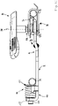
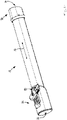
- connection part 16 designed as an extension piece on its own.
- the extension piece 16 extends along a longitudinal direction 12.
- the extension piece 16 has a tube section which at one end (in figure 14 left) the connecting section 22 and at the other end (in figure 14 right) has the connecting section 20.
- connection section 22 of the extension piece 16 is designed in accordance with the connection section 22 of the connection part 16 described above (identical or functionally identical elements are provided with identical reference symbols). In order to avoid repetition, reference is therefore made to the above statements on the connection section 22 of the connection part 16 .
- connection section 20 of the extension piece 16 is designed in accordance with the connection section 20 of the connection part 14 described above (identical or functionally identical elements are provided with identical reference symbols). In order to avoid repetition, reference is therefore made to the above statements on the connection section 20 of the connection part 14 .
- the flow channel 42 is arranged in the first section 74 .
- the flow channel 74 extends between the connecting section 22 and the connecting section 20 of the extension piece 16.
- the connection openings 36 and 38 both open into the flow channel 42.
- the electrical plug connector 28 and the counter-element 32 are arranged on the connecting section 20
- the clamping element 34 or the clamping device 82 and the electrical plug connector 30 are arranged on the connecting section 22 .
- the electrical plug connector 28 and the electrical plug connector 30 are electrically or electronically connected to one another by means of electrical or electronic lines routed through the further section 76 .
- electricity and / or Control signals are transmitted through the extension piece 16.
- connection arrangement 10 or a hand-held machine tool equipped with the connection arrangement 10 works as follows (explained with reference to the connection parts 14 and 16):
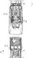
- the connecting parts 14, 16 are first positioned relative to one another in such a way that the connecting sections 20, 22 are aligned with one another in such a way that the connecting sections 20, 22 can be plugged together (cf. e.g. figure 4 , 6 or 11 ).
- the connecting sections 20, 22 are then plugged together and the clamping lever 80 can be closed (cf. e.g. figure 3 or 9 ).
- the tensioning element 34 and the counter-element 32 come into engagement with one another (gripping from behind), since the tensioning element 34 is pretensioned relative to the counter-element 32 by the spring 92 (cf. e.g. figure 8 ).
- the connectors 28, 30 are also connected to one another when they are plugged together. If an end position is reached during plugging, e.g. when the bearing section 56 of the connecting section 20 comes into contact with the bearing section 58 of the connecting section 22, the connection openings 36, 38 are also aligned with one another, so that the flow channel 40 and the flow channel 42 are flow-connected to one another are.
- the clamping device 82 By pivoting the clamping lever 80, the clamping device 82 is actuated, which acts on the clamping element 34, which engages behind the counter-element 32 (see FIG figure 9 ). As a result, the clamping element 34 is pulled (axially) inwards along the longitudinal direction 12 by means of the eccentric 102 in the connecting part 16 . Because the connecting parts 14, 16 rest against one another at the connecting sections 20, 22, for example by means of the feed sections 56, 58, and the clamping element 34 applies a tensile force to the counter-element 32, the connecting parts 14, 16 are clamped together.
- the clamping lever 80 To release, the clamping lever 80 must be pivoted in the opening direction, whereby the clamping device 82 is actuated and the clamping element 34 is relieved (tensile force is reduced). The tensioning element 34 and the counter-element 32 are still engaged with one another.
- the clamping lever 80 In order to disengage the clamping element 34 and the counter-element 32, the clamping lever 80 must be pivoted further in the opening direction or, alternatively, the button 104 must be actuated. As a result, the clamping element 34 is pivoted so that this to Counter element 32 is disengaged. The mechanical clamping connection is thus released.
- the connecting parts 14, 16 can then be separated or pulled apart from one another. By separating the electrical plug connectors 28, 20 and the connection openings 26, 38, the electrical plug connection and the flow connection between the connecting parts 14, 16 are also released.
Landscapes
- Engineering & Computer Science (AREA)
- Mechanical Engineering (AREA)
- General Engineering & Computer Science (AREA)
- Connector Housings Or Holding Contact Members (AREA)
- Details Of Connecting Devices For Male And Female Coupling (AREA)
- Portable Power Tools In General (AREA)
- Grinding-Machine Dressing And Accessory Apparatuses (AREA)
- Finish Polishing, Edge Sharpening, And Grinding By Specific Grinding Devices (AREA)
- Quick-Acting Or Multi-Walled Pipe Joints (AREA)
- Feeding Of Workpieces (AREA)
- Handcart (AREA)
- Automatic Tool Replacement In Machine Tools (AREA)
- Electric Vacuum Cleaner (AREA)
Applications Claiming Priority (2)
| Application Number | Priority Date | Filing Date | Title |
|---|---|---|---|
| DE102019129823.7A DE102019129823A1 (de) | 2019-11-05 | 2019-11-05 | Verbindungsanordnung für eine handgeführte Werkzeugmaschine und handgeführte Werkzeugmaschine |
| PCT/EP2020/071597 WO2021089206A1 (de) | 2019-11-05 | 2020-07-30 | Verbindungsanordnung für eine handgeführte werkzeugmaschine und handgeführte werkzeugmaschine |
Publications (2)
| Publication Number | Publication Date |
|---|---|
| EP3880401A1 EP3880401A1 (de) | 2021-09-22 |
| EP3880401B1 true EP3880401B1 (de) | 2022-11-16 |
Family
ID=71950609
Family Applications (1)
| Application Number | Title | Priority Date | Filing Date |
|---|---|---|---|
| EP20751502.4A Active EP3880401B1 (de) | 2019-11-05 | 2020-07-30 | Verbindungsanordnung für eine handgeführte werkzeugmaschine und handgeführte werkzeugmaschine |
Country Status (8)
| Country | Link |
|---|---|
| US (1) | US12115641B2 (pl) |
| EP (1) | EP3880401B1 (pl) |
| JP (1) | JP7539390B2 (pl) |
| CN (1) | CN113272100B (pl) |
| DE (1) | DE102019129823A1 (pl) |
| FI (1) | FI3880401T3 (pl) |
| PL (1) | PL3880401T3 (pl) |
| WO (1) | WO2021089206A1 (pl) |
Families Citing this family (1)
| Publication number | Priority date | Publication date | Assignee | Title |
|---|---|---|---|---|
| US20260085776A1 (en) * | 2024-09-23 | 2026-03-26 | K&W Tools Co., Ltd | Telescopic pipe structure |
Family Cites Families (32)
| Publication number | Priority date | Publication date | Assignee | Title |
|---|---|---|---|---|
| US2987693A (en) * | 1957-09-03 | 1961-06-06 | Itt | Electrical connector assembly |
| DE29508203U1 (de) * | 1995-05-15 | 1995-08-03 | Hohmann, Joachim, 13503 Berlin | Verlängerbare Kettensäge |
| JP3026169U (ja) | 1995-12-21 | 1996-07-02 | 有限会社佐藤工業所 | 園芸用作業具 |
| JP3817241B2 (ja) | 2003-11-07 | 2006-09-06 | 日本圧着端子製造株式会社 | コネクタハウジング組立体、電気コネクタ組立体及び電線付き電気コネクタ |
| US7484300B2 (en) * | 2004-09-09 | 2009-02-03 | Black & Decker Inc. | Extensible pole saw having separable sections |
| US9591809B2 (en) * | 2007-02-06 | 2017-03-14 | Mtd Products Inc | Split power tool |
| DE102007012394A1 (de) | 2007-03-15 | 2008-09-18 | Festool Gmbh | Griffstab einer handgeführten Werkzeugmaschine |
| DE102007029617A1 (de) | 2007-06-27 | 2009-01-08 | Andreas Stihl Ag & Co. Kg | Schlauchanschlussstück und hangeführtes Arbeitsgerät |
| US7774901B1 (en) * | 2007-12-05 | 2010-08-17 | Ho Cheng Garden Tools Co., Ltd. | Retractable handle assembly for tool |
| US8574037B2 (en) * | 2010-06-11 | 2013-11-05 | David W. Kresge | Multi-purpose extended reach tool |
| US20150089821A1 (en) * | 2011-09-09 | 2015-04-02 | Stretta, Inc. | Extendable pole system and methods of using the same |
| US8875350B2 (en) * | 2012-06-29 | 2014-11-04 | The Wooster Brush Company | Extension pole with reversible tip assembly |
| JP5843167B2 (ja) * | 2012-11-15 | 2016-01-13 | 住友電装株式会社 | レバー式コネクタ |
| KR101503507B1 (ko) * | 2014-04-09 | 2015-03-18 | 주식회사 경신 | 차량용 커넥터 |
| DE102014109583A1 (de) * | 2014-06-13 | 2015-12-17 | Metabowerke Gmbh | Langhalsschleifer |
| JP6197779B2 (ja) * | 2014-11-04 | 2017-09-20 | 住友電装株式会社 | レバー式コネクタ |
| US10080471B2 (en) * | 2015-12-21 | 2018-09-25 | Electrolux Home Care Products, Inc. | Versatile vacuum cleaners |
| JP6610952B2 (ja) * | 2016-03-18 | 2019-11-27 | 住友電装株式会社 | レバー式コネクタ |
| DE102016106556A1 (de) | 2016-04-11 | 2017-10-12 | Festool Gmbh | Hand-Werkzeugmaschine mit einem Absaugschlauch |
| JP6492029B2 (ja) * | 2016-05-30 | 2019-03-27 | 矢崎総業株式会社 | コネクタ |
| JP6572188B2 (ja) * | 2016-09-07 | 2019-09-04 | 矢崎総業株式会社 | レバー式コネクタ |
| JP6564750B2 (ja) * | 2016-09-07 | 2019-08-21 | 矢崎総業株式会社 | レバー式コネクタ |
| EP3539436A4 (en) | 2016-11-09 | 2019-11-06 | Sharp Kabushiki Kaisha | EXTENSION TUBE FOR ELECTRIC VACUUM CLEANERS |
| CN106956174A (zh) * | 2017-02-17 | 2017-07-18 | 东莞产权交易中心 | 一种光网电动墙壁打磨机 |
| JP6653291B2 (ja) * | 2017-05-19 | 2020-02-26 | 矢崎総業株式会社 | コネクタ装置 |
| JP6872237B2 (ja) | 2017-07-21 | 2021-05-19 | 株式会社永木精機 | 操作棒の連結構造 |
| US10270208B1 (en) * | 2017-10-20 | 2019-04-23 | Lear Corporation | Electrical connector with assist lever |
| JP2019091610A (ja) * | 2017-11-14 | 2019-06-13 | 住友電装株式会社 | コネクタ |
| US12022770B2 (en) * | 2018-03-02 | 2024-07-02 | Techtronic Outdoor Products Technology Limited | Coupler for a tool |
| JP6820293B2 (ja) * | 2018-07-06 | 2021-01-27 | 矢崎総業株式会社 | コネクタ |
| JP2021015720A (ja) * | 2019-07-12 | 2021-02-12 | 矢崎総業株式会社 | レバー式コネクタ |
| CN116267177A (zh) * | 2021-12-07 | 2023-06-23 | 南京泉峰科技有限公司 | 动力工具及折叠杆组件 |
-
2019
- 2019-11-05 DE DE102019129823.7A patent/DE102019129823A1/de not_active Ceased
-
2020
- 2020-07-30 WO PCT/EP2020/071597 patent/WO2021089206A1/de not_active Ceased
- 2020-07-30 CN CN202080007875.8A patent/CN113272100B/zh active Active
- 2020-07-30 EP EP20751502.4A patent/EP3880401B1/de active Active
- 2020-07-30 US US17/414,550 patent/US12115641B2/en active Active
- 2020-07-30 PL PL20751502.4T patent/PL3880401T3/pl unknown
- 2020-07-30 JP JP2021538837A patent/JP7539390B2/ja active Active
- 2020-07-30 FI FIEP20751502.4T patent/FI3880401T3/de active
Also Published As
| Publication number | Publication date |
|---|---|
| CN113272100B (zh) | 2023-08-04 |
| PL3880401T3 (pl) | 2023-03-20 |
| JP7539390B2 (ja) | 2024-08-23 |
| US12115641B2 (en) | 2024-10-15 |
| DE102019129823A1 (de) | 2021-05-06 |
| EP3880401A1 (de) | 2021-09-22 |
| WO2021089206A1 (de) | 2021-05-14 |
| CN113272100A (zh) | 2021-08-17 |
| US20220009074A1 (en) | 2022-01-13 |
| JP2023501839A (ja) | 2023-01-20 |
| FI3880401T3 (en) | 2022-12-15 |
Similar Documents
| Publication | Publication Date | Title |
|---|---|---|
| EP3880407B1 (de) | Verbindungsanordnung für eine handgeführte werkzeugmaschine und handgeführte werkzeugmaschine | |
| EP1970168B1 (de) | Griffstab einer handgeführten Werkzeugmaschine | |
| DE102005031142A1 (de) | Spannvorrichtung, Grundbacken und Aufsatzbacken dafür | |
| EP1961524B1 (de) | Vorrichtung zum Verbinden einer Werkstück-Bearbeitungsmaschine mit einem Absaugschlauch | |
| DE4208632A1 (de) | Kettenspannwerkzeug | |
| EP1412116A1 (de) | Wechselvorrichtung für spannköpfe mit mehreren spannbacken | |
| DE2831140C2 (pl) | ||
| DE202011050396U1 (de) | Zuführeinrichtung zur Bedüsung eines Werkzeugs eines handhaltbaren Motorarbeitsgerätes und ebensolches Motorarbeitsgerät | |
| DE112018006391T5 (de) | Abflusskabel-entkopplungswerkzeuge | |
| EP3880401A1 (de) | Verbindungsanordnung für eine handgeführte werkzeugmaschine und handgeführte werkzeugmaschine | |
| DE102015119060B3 (de) | Spannvorrichtung | |
| EP0773383A1 (de) | Schutzvorrichtung für Gelenkwellen mit einem abnehmbaren Schutzrichter | |
| EP1388616A1 (de) | Vorrichtung zum Kuppeln und Entkuppeln der Anschlussenden von Druckmittelleitungen | |
| EP1500321B1 (de) | Universell einsetzbares Anspannsystem | |
| DE102015119061B3 (de) | Spannvorrichtung | |
| EP1709931A2 (de) | Motorelement, insbesondere dentalmedizinisches Handstück mit einer lösbaren Kupplung für einen Werkzeughalter | |
| DE202007001145U1 (de) | Strukturverbesserung eines Hilfsverbindungsstücks für Werkzeuge | |
| DE102012217474A1 (de) | Handschraubvorrichtung mit abnehmbarem Griffteil | |
| DE102011009722A1 (de) | Adapterelement für einen Schraubenschlüssel | |
| DE102008010503A1 (de) | Mechanisierte Unterstützungsvorrichtung zum Anschließen und Abkoppeln von vor allem hydraulischen Verbindungen | |
| DE102014114327B4 (de) | Auswerferkupplung | |
| EP4010604B1 (de) | Verbindungsvorrichtung zum starren verbinden zweier wellen und wellenanordnung mit einer verbindungsvorrichtung | |
| DE202024104808U1 (de) | Werkzeug zur Demontage einer Riemenscheibe von der dazugehörigen sich drehenden Welle; insbesondere zur Demontage einer Riemenscheibe, die mit einem Dämpfer für Drehschwingungen von der Motorwelle eines Fahrzeugs ausgestattet ist | |
| AT403640B (de) | Schnellkupplung zum anbau eines arbeitsgerätes an einem schlepper | |
| DE20119604U1 (de) | Spanableiteinrichtung an einem Elektrohandwerkzeug |
Legal Events
| Date | Code | Title | Description |
|---|---|---|---|
| STAA | Information on the status of an ep patent application or granted ep patent |
Free format text: STATUS: UNKNOWN |
|
| STAA | Information on the status of an ep patent application or granted ep patent |
Free format text: STATUS: THE INTERNATIONAL PUBLICATION HAS BEEN MADE |
|
| PUAI | Public reference made under article 153(3) epc to a published international application that has entered the european phase |
Free format text: ORIGINAL CODE: 0009012 |
|
| STAA | Information on the status of an ep patent application or granted ep patent |
Free format text: STATUS: REQUEST FOR EXAMINATION WAS MADE |
|
| 17P | Request for examination filed |
Effective date: 20210616 |
|
| AK | Designated contracting states |
Kind code of ref document: A1 Designated state(s): AL AT BE BG CH CY CZ DE DK EE ES FI FR GB GR HR HU IE IS IT LI LT LU LV MC MK MT NL NO PL PT RO RS SE SI SK SM TR |
|
| STAA | Information on the status of an ep patent application or granted ep patent |
Free format text: STATUS: EXAMINATION IS IN PROGRESS |
|
| 17Q | First examination report despatched |
Effective date: 20220112 |
|
| GRAP | Despatch of communication of intention to grant a patent |
Free format text: ORIGINAL CODE: EPIDOSNIGR1 |
|
| STAA | Information on the status of an ep patent application or granted ep patent |
Free format text: STATUS: GRANT OF PATENT IS INTENDED |
|
| INTG | Intention to grant announced |
Effective date: 20220322 |
|
| GRAJ | Information related to disapproval of communication of intention to grant by the applicant or resumption of examination proceedings by the epo deleted |
Free format text: ORIGINAL CODE: EPIDOSDIGR1 |
|
| GRAL | Information related to payment of fee for publishing/printing deleted |
Free format text: ORIGINAL CODE: EPIDOSDIGR3 |
|
| GRAS | Grant fee paid |
Free format text: ORIGINAL CODE: EPIDOSNIGR3 |
|
| STAA | Information on the status of an ep patent application or granted ep patent |
Free format text: STATUS: EXAMINATION IS IN PROGRESS |
|
| INTC | Intention to grant announced (deleted) | ||
| GRAP | Despatch of communication of intention to grant a patent |
Free format text: ORIGINAL CODE: EPIDOSNIGR1 |
|
| STAA | Information on the status of an ep patent application or granted ep patent |
Free format text: STATUS: GRANT OF PATENT IS INTENDED |
|
| GRAA | (expected) grant |
Free format text: ORIGINAL CODE: 0009210 |
|
| STAA | Information on the status of an ep patent application or granted ep patent |
Free format text: STATUS: THE PATENT HAS BEEN GRANTED |
|
| DAV | Request for validation of the european patent (deleted) | ||
| DAX | Request for extension of the european patent (deleted) | ||
| INTG | Intention to grant announced |
Effective date: 20220926 |
|
| AK | Designated contracting states |
Kind code of ref document: B1 Designated state(s): AL AT BE BG CH CY CZ DE DK EE ES FI FR GB GR HR HU IE IS IT LI LT LU LV MC MK MT NL NO PL PT RO RS SE SI SK SM TR |
|
| REG | Reference to a national code |
Ref country code: GB Ref legal event code: FG4D Free format text: NOT ENGLISH |
|
| REG | Reference to a national code |
Ref country code: CH Ref legal event code: EP |
|
| REG | Reference to a national code |
Ref country code: DE Ref legal event code: R096 Ref document number: 502020002021 Country of ref document: DE |
|
| REG | Reference to a national code |
Ref country code: IE Ref legal event code: FG4D Free format text: LANGUAGE OF EP DOCUMENT: GERMAN |
|
| REG | Reference to a national code |
Ref country code: AT Ref legal event code: REF Ref document number: 1531500 Country of ref document: AT Kind code of ref document: T Effective date: 20221215 |
|
| REG | Reference to a national code |
Ref country code: NL Ref legal event code: FP |
|
| REG | Reference to a national code |
Ref country code: LT Ref legal event code: MG9D |
|
| PG25 | Lapsed in a contracting state [announced via postgrant information from national office to epo] |
Ref country code: SE Free format text: LAPSE BECAUSE OF FAILURE TO SUBMIT A TRANSLATION OF THE DESCRIPTION OR TO PAY THE FEE WITHIN THE PRESCRIBED TIME-LIMIT Effective date: 20221116 Ref country code: PT Free format text: LAPSE BECAUSE OF FAILURE TO SUBMIT A TRANSLATION OF THE DESCRIPTION OR TO PAY THE FEE WITHIN THE PRESCRIBED TIME-LIMIT Effective date: 20230316 Ref country code: NO Free format text: LAPSE BECAUSE OF FAILURE TO SUBMIT A TRANSLATION OF THE DESCRIPTION OR TO PAY THE FEE WITHIN THE PRESCRIBED TIME-LIMIT Effective date: 20230216 Ref country code: LT Free format text: LAPSE BECAUSE OF FAILURE TO SUBMIT A TRANSLATION OF THE DESCRIPTION OR TO PAY THE FEE WITHIN THE PRESCRIBED TIME-LIMIT Effective date: 20221116 Ref country code: ES Free format text: LAPSE BECAUSE OF FAILURE TO SUBMIT A TRANSLATION OF THE DESCRIPTION OR TO PAY THE FEE WITHIN THE PRESCRIBED TIME-LIMIT Effective date: 20221116 |
|
| REG | Reference to a national code |
Ref country code: DE Ref legal event code: R082 Ref document number: 502020002021 Country of ref document: DE Representative=s name: MAIWALD GMBH, DE |
|
| PG25 | Lapsed in a contracting state [announced via postgrant information from national office to epo] |
Ref country code: RS Free format text: LAPSE BECAUSE OF FAILURE TO SUBMIT A TRANSLATION OF THE DESCRIPTION OR TO PAY THE FEE WITHIN THE PRESCRIBED TIME-LIMIT Effective date: 20221116 Ref country code: LV Free format text: LAPSE BECAUSE OF FAILURE TO SUBMIT A TRANSLATION OF THE DESCRIPTION OR TO PAY THE FEE WITHIN THE PRESCRIBED TIME-LIMIT Effective date: 20221116 Ref country code: IS Free format text: LAPSE BECAUSE OF FAILURE TO SUBMIT A TRANSLATION OF THE DESCRIPTION OR TO PAY THE FEE WITHIN THE PRESCRIBED TIME-LIMIT Effective date: 20230316 Ref country code: HR Free format text: LAPSE BECAUSE OF FAILURE TO SUBMIT A TRANSLATION OF THE DESCRIPTION OR TO PAY THE FEE WITHIN THE PRESCRIBED TIME-LIMIT Effective date: 20221116 Ref country code: GR Free format text: LAPSE BECAUSE OF FAILURE TO SUBMIT A TRANSLATION OF THE DESCRIPTION OR TO PAY THE FEE WITHIN THE PRESCRIBED TIME-LIMIT Effective date: 20230217 |
|
| P01 | Opt-out of the competence of the unified patent court (upc) registered |
Effective date: 20230512 |
|
| PG25 | Lapsed in a contracting state [announced via postgrant information from national office to epo] |
Ref country code: SM Free format text: LAPSE BECAUSE OF FAILURE TO SUBMIT A TRANSLATION OF THE DESCRIPTION OR TO PAY THE FEE WITHIN THE PRESCRIBED TIME-LIMIT Effective date: 20221116 Ref country code: RO Free format text: LAPSE BECAUSE OF FAILURE TO SUBMIT A TRANSLATION OF THE DESCRIPTION OR TO PAY THE FEE WITHIN THE PRESCRIBED TIME-LIMIT Effective date: 20221116 Ref country code: EE Free format text: LAPSE BECAUSE OF FAILURE TO SUBMIT A TRANSLATION OF THE DESCRIPTION OR TO PAY THE FEE WITHIN THE PRESCRIBED TIME-LIMIT Effective date: 20221116 Ref country code: DK Free format text: LAPSE BECAUSE OF FAILURE TO SUBMIT A TRANSLATION OF THE DESCRIPTION OR TO PAY THE FEE WITHIN THE PRESCRIBED TIME-LIMIT Effective date: 20221116 Ref country code: CZ Free format text: LAPSE BECAUSE OF FAILURE TO SUBMIT A TRANSLATION OF THE DESCRIPTION OR TO PAY THE FEE WITHIN THE PRESCRIBED TIME-LIMIT Effective date: 20221116 |
|
| REG | Reference to a national code |
Ref country code: DE Ref legal event code: R097 Ref document number: 502020002021 Country of ref document: DE |
|
| PG25 | Lapsed in a contracting state [announced via postgrant information from national office to epo] |
Ref country code: SK Free format text: LAPSE BECAUSE OF FAILURE TO SUBMIT A TRANSLATION OF THE DESCRIPTION OR TO PAY THE FEE WITHIN THE PRESCRIBED TIME-LIMIT Effective date: 20221116 Ref country code: AL Free format text: LAPSE BECAUSE OF FAILURE TO SUBMIT A TRANSLATION OF THE DESCRIPTION OR TO PAY THE FEE WITHIN THE PRESCRIBED TIME-LIMIT Effective date: 20221116 |
|
| PLBE | No opposition filed within time limit |
Free format text: ORIGINAL CODE: 0009261 |
|
| STAA | Information on the status of an ep patent application or granted ep patent |
Free format text: STATUS: NO OPPOSITION FILED WITHIN TIME LIMIT |
|
| 26N | No opposition filed |
Effective date: 20230817 |
|
| PG25 | Lapsed in a contracting state [announced via postgrant information from national office to epo] |
Ref country code: SI Free format text: LAPSE BECAUSE OF FAILURE TO SUBMIT A TRANSLATION OF THE DESCRIPTION OR TO PAY THE FEE WITHIN THE PRESCRIBED TIME-LIMIT Effective date: 20221116 |
|
| PG25 | Lapsed in a contracting state [announced via postgrant information from national office to epo] |
Ref country code: MC Free format text: LAPSE BECAUSE OF FAILURE TO SUBMIT A TRANSLATION OF THE DESCRIPTION OR TO PAY THE FEE WITHIN THE PRESCRIBED TIME-LIMIT Effective date: 20221116 |
|
| PG25 | Lapsed in a contracting state [announced via postgrant information from national office to epo] |
Ref country code: MC Free format text: LAPSE BECAUSE OF FAILURE TO SUBMIT A TRANSLATION OF THE DESCRIPTION OR TO PAY THE FEE WITHIN THE PRESCRIBED TIME-LIMIT Effective date: 20221116 |
|
| REG | Reference to a national code |
Ref country code: CH Ref legal event code: PL |
|
| REG | Reference to a national code |
Ref country code: BE Ref legal event code: MM Effective date: 20230731 |
|
| PG25 | Lapsed in a contracting state [announced via postgrant information from national office to epo] |
Ref country code: LU Free format text: LAPSE BECAUSE OF NON-PAYMENT OF DUE FEES Effective date: 20230730 |
|
| PG25 | Lapsed in a contracting state [announced via postgrant information from national office to epo] |
Ref country code: LU Free format text: LAPSE BECAUSE OF NON-PAYMENT OF DUE FEES Effective date: 20230730 |
|
| REG | Reference to a national code |
Ref country code: IE Ref legal event code: MM4A |
|
| PG25 | Lapsed in a contracting state [announced via postgrant information from national office to epo] |
Ref country code: CH Free format text: LAPSE BECAUSE OF NON-PAYMENT OF DUE FEES Effective date: 20230731 |
|
| PG25 | Lapsed in a contracting state [announced via postgrant information from national office to epo] |
Ref country code: BE Free format text: LAPSE BECAUSE OF NON-PAYMENT OF DUE FEES Effective date: 20230731 |
|
| PG25 | Lapsed in a contracting state [announced via postgrant information from national office to epo] |
Ref country code: IE Free format text: LAPSE BECAUSE OF NON-PAYMENT OF DUE FEES Effective date: 20230730 |
|
| PG25 | Lapsed in a contracting state [announced via postgrant information from national office to epo] |
Ref country code: IE Free format text: LAPSE BECAUSE OF NON-PAYMENT OF DUE FEES Effective date: 20230730 |
|
| PG25 | Lapsed in a contracting state [announced via postgrant information from national office to epo] |
Ref country code: BG Free format text: LAPSE BECAUSE OF FAILURE TO SUBMIT A TRANSLATION OF THE DESCRIPTION OR TO PAY THE FEE WITHIN THE PRESCRIBED TIME-LIMIT Effective date: 20221116 |
|
| PG25 | Lapsed in a contracting state [announced via postgrant information from national office to epo] |
Ref country code: BG Free format text: LAPSE BECAUSE OF FAILURE TO SUBMIT A TRANSLATION OF THE DESCRIPTION OR TO PAY THE FEE WITHIN THE PRESCRIBED TIME-LIMIT Effective date: 20221116 |
|
| PG25 | Lapsed in a contracting state [announced via postgrant information from national office to epo] |
Ref country code: CY Free format text: LAPSE BECAUSE OF FAILURE TO SUBMIT A TRANSLATION OF THE DESCRIPTION OR TO PAY THE FEE WITHIN THE PRESCRIBED TIME-LIMIT; INVALID AB INITIO Effective date: 20200730 |
|
| PG25 | Lapsed in a contracting state [announced via postgrant information from national office to epo] |
Ref country code: HU Free format text: LAPSE BECAUSE OF FAILURE TO SUBMIT A TRANSLATION OF THE DESCRIPTION OR TO PAY THE FEE WITHIN THE PRESCRIBED TIME-LIMIT; INVALID AB INITIO Effective date: 20200730 |
|
| PGFP | Annual fee paid to national office [announced via postgrant information from national office to epo] |
Ref country code: NL Payment date: 20250723 Year of fee payment: 6 |
|
| PGFP | Annual fee paid to national office [announced via postgrant information from national office to epo] |
Ref country code: FI Payment date: 20250722 Year of fee payment: 6 |
|
| PGFP | Annual fee paid to national office [announced via postgrant information from national office to epo] |
Ref country code: DE Payment date: 20250730 Year of fee payment: 6 |
|
| PGFP | Annual fee paid to national office [announced via postgrant information from national office to epo] |
Ref country code: PL Payment date: 20250721 Year of fee payment: 6 Ref country code: IT Payment date: 20250731 Year of fee payment: 6 |
|
| PGFP | Annual fee paid to national office [announced via postgrant information from national office to epo] |
Ref country code: GB Payment date: 20250724 Year of fee payment: 6 |
|
| PGFP | Annual fee paid to national office [announced via postgrant information from national office to epo] |
Ref country code: AT Payment date: 20251020 Year of fee payment: 5 Ref country code: FR Payment date: 20250723 Year of fee payment: 6 |
|
| PG25 | Lapsed in a contracting state [announced via postgrant information from national office to epo] |
Ref country code: TR Free format text: LAPSE BECAUSE OF FAILURE TO SUBMIT A TRANSLATION OF THE DESCRIPTION OR TO PAY THE FEE WITHIN THE PRESCRIBED TIME-LIMIT Effective date: 20221116 |