EP3879892A1 - Procédé et système de procédure d'accès aléatoire et de défaillance de liaison radio dans une agrégation de porteuses inter-enb - Google Patents
Procédé et système de procédure d'accès aléatoire et de défaillance de liaison radio dans une agrégation de porteuses inter-enb Download PDFInfo
- Publication number
- EP3879892A1 EP3879892A1 EP21172024.8A EP21172024A EP3879892A1 EP 3879892 A1 EP3879892 A1 EP 3879892A1 EP 21172024 A EP21172024 A EP 21172024A EP 3879892 A1 EP3879892 A1 EP 3879892A1
- Authority
- EP
- European Patent Office
- Prior art keywords
- scell
- random access
- message
- senb
- rnti
- Prior art date
- Legal status (The legal status is an assumption and is not a legal conclusion. Google has not performed a legal analysis and makes no representation as to the accuracy of the status listed.)
- Pending
Links
Images


Classifications
-
- H—ELECTRICITY
- H04—ELECTRIC COMMUNICATION TECHNIQUE
- H04L—TRANSMISSION OF DIGITAL INFORMATION, e.g. TELEGRAPHIC COMMUNICATION
- H04L5/00—Arrangements affording multiple use of the transmission path
- H04L5/0001—Arrangements for dividing the transmission path
- H04L5/0003—Two-dimensional division
- H04L5/0005—Time-frequency
- H04L5/0007—Time-frequency the frequencies being orthogonal, e.g. OFDM(A), DMT
-
- H—ELECTRICITY
- H04—ELECTRIC COMMUNICATION TECHNIQUE
- H04W—WIRELESS COMMUNICATION NETWORKS
- H04W56/00—Synchronisation arrangements
- H04W56/0005—Synchronisation arrangements synchronizing of arrival of multiple uplinks
-
- H—ELECTRICITY
- H04—ELECTRIC COMMUNICATION TECHNIQUE
- H04L—TRANSMISSION OF DIGITAL INFORMATION, e.g. TELEGRAPHIC COMMUNICATION
- H04L41/00—Arrangements for maintenance, administration or management of data switching networks, e.g. of packet switching networks
- H04L41/06—Management of faults, events, alarms or notifications
- H04L41/0686—Additional information in the notification, e.g. enhancement of specific meta-data
-
- H—ELECTRICITY
- H04—ELECTRIC COMMUNICATION TECHNIQUE
- H04L—TRANSMISSION OF DIGITAL INFORMATION, e.g. TELEGRAPHIC COMMUNICATION
- H04L5/00—Arrangements affording multiple use of the transmission path
- H04L5/003—Arrangements for allocating sub-channels of the transmission path
- H04L5/0032—Distributed allocation, i.e. involving a plurality of allocating devices, each making partial allocation
-
- H—ELECTRICITY
- H04—ELECTRIC COMMUNICATION TECHNIQUE
- H04W—WIRELESS COMMUNICATION NETWORKS
- H04W72/00—Local resource management
- H04W72/20—Control channels or signalling for resource management
- H04W72/23—Control channels or signalling for resource management in the downlink direction of a wireless link, i.e. towards a terminal
-
- H—ELECTRICITY
- H04—ELECTRIC COMMUNICATION TECHNIQUE
- H04W—WIRELESS COMMUNICATION NETWORKS
- H04W74/00—Wireless channel access, e.g. scheduled or random access
- H04W74/002—Transmission of channel access control information
- H04W74/004—Transmission of channel access control information in the uplink, i.e. towards network
-
- H—ELECTRICITY
- H04—ELECTRIC COMMUNICATION TECHNIQUE
- H04W—WIRELESS COMMUNICATION NETWORKS
- H04W74/00—Wireless channel access, e.g. scheduled or random access
- H04W74/08—Non-scheduled or contention based access, e.g. random access, ALOHA, CSMA [Carrier Sense Multiple Access]
- H04W74/0833—Non-scheduled or contention based access, e.g. random access, ALOHA, CSMA [Carrier Sense Multiple Access] using a random access procedure
-
- H—ELECTRICITY
- H04—ELECTRIC COMMUNICATION TECHNIQUE
- H04W—WIRELESS COMMUNICATION NETWORKS
- H04W76/00—Connection management
- H04W76/10—Connection setup
-
- H—ELECTRICITY
- H04—ELECTRIC COMMUNICATION TECHNIQUE
- H04W—WIRELESS COMMUNICATION NETWORKS
- H04W76/00—Connection management
- H04W76/10—Connection setup
- H04W76/15—Setup of multiple wireless link connections
-
- H—ELECTRICITY
- H04—ELECTRIC COMMUNICATION TECHNIQUE
- H04W—WIRELESS COMMUNICATION NETWORKS
- H04W76/00—Connection management
- H04W76/10—Connection setup
- H04W76/18—Management of setup rejection or failure
Definitions
- the present invention relates to a wireless network and more particularly to an inter-eNB carrier aggregation in the wireless network deploying dual connectivity.
- UE User Equipment
- carrier aggregation has been developed in which the UE is served by multiple serving cells. When demand for more data rate arises for a UE then more than one serving cell on different carrier frequencies is configured for the UE.
- the serving cells are governed by a single eNodeB (eNB) and the deployment is called as intra eNB carrier aggregation.
- eNB eNodeB
- intra-eNB carrier aggregation since all the processing related to the transmissions on the multiple carrier frequencies happen within the same eNB, an ideal backhaul exists between the multiple serving cells to which the UE is connected.
- an emerging technology called dual connectivity with an inter-eNB carrier aggregation allows the UE to maintain connectivity to multiple serving cells where it is assumed that non-ideal backhaul exists between the network nodes corresponding to the multiple serving cells.
- the serving carrier providing coverage to the UE serves as the mobility anchor and the carriers from small provide extra capacity. It is possible to use ideal backhaul using very high speed and very low latency fiber optic links between the serving cell served by the mobility anchor and the small cell layer, however the deployment cost would be prohibitive and mobile operator would leverage on existing non-ideal backhaul links.
- the inter-eNB carrier aggregation in which the UE is served by serving cells associated with different eNBs.
- the UE When carrier aggregation between two cells controlled by two geographically separated eNBs is envisioned then the UE needs to perform uplink synchronization towards respective cells.
- dual connectivity is envisioned such that UE maintains physical links with the two cells controlled by two geographically separated eNBs. Further, the UE maintains dual connectivity both in downlink and uplink or only downlink. In uplink, the dual connectivity towards the two cells could be simultaneous or could be time multiplexed.
- the uplink timing advance to the mobility anchor i.e anchor eNB also called as Master eNB (MeNB) is different from the uplink timing advance towards the assisting eNB also called as Small eNB or Secondary eNB (SeNB) since they are geographically separated and operating on two separate frequencies (component carriers) in different frequency bands.
- the UE is served by a Primary serving cell (PCell) of MeNB on a serving frequency providing coverage and mobility and is aggregated with one or more Secondary cell (SCells) of the SeNB and/or the MeNB served on other serving frequencies respectively providing offloading opportunity to increase data rates.
- PCell Primary serving cell
- SCells Secondary cell
- RRH Remote Radio Head
- the RRH links to a macro eNB are ideal (typically fiber optic links) whereas link between the MeNB and SeNB is non-ideal in the context of dual connectivity mode of operation.
- the UE Whenever the UE needs to uplink synchronize on serving frequency assigned to SCell typically served by the SeNB, the UE is required to perform a random access procedure.
- the UE performs the random access procedure after activation of the SCell of the MeNB and only after receiving a Physical Downlink Control Channel (PDCCH) order from the SCell such that the response to the random access preamble transmitted on the SCell is received in the PCell of the MeNB.
- PDCCH Physical Downlink Control Channel
- RLF uplink Radio Link Failure
- legacy intra-eNB carrier aggregation once the UE detects RLF on the PCell, the UE starts RRC connection re-establishment procedure whereas RLF on the SCell is left to PCell handling.
- legacy intra-eNB carrier aggregation mode of operation of the UE when transmission and reception of the EPS bearer data is carried on both the PCell and the SCell of the same eNB, the re-establishment leads to service interruption on both the PCell and the SCell, since in the legacy intra-eNB carrier aggregation a Radio Link Control (RLC) entity and PDCP entity are transparent to the carrier aggregation.
- RLC Radio Link Control
- the UE has to recover from the error by a re-establishment procedure.
- the PCell of the MeNB and the SCell of the SeNB carry data for different bearers of the UE.
- uplink RLF occurs due to RLC error then the RLC entity in the UE is able to distinguish whether the error condition occurred on the PCell served by the MeNB or the SCell by the SeNB.
- the legacy procedure of RRC connection re-establishment is triggered when RLC error occur on SCell of the SeNB then it would interrupt on-going services and can cause loss of data for both PCell as well as SCell.
- the legacy procedure for re-establishment of a radio Resource Control (RRC) connection requires more signaling effectively increasing battery power consumption.
- RRC radio Resource Control
- the principal object of the embodiments herein is to provide a method and system for configuring a User Equipment (UE) for dual connectivity mode of operation in a wireless network deploying an inter-eNB carrier aggregation.
- UE User Equipment
- Another object of the invention is to provide a method for allowing the UE to initiate a random access procedure on a Secondary eNB (SeNB) during an addition or a replacement of a Secondary Cell (SCell) of the SeNB.
- SeNB Secondary eNB
- Another object of the invention is to provide a method for handling a Radio Link Failure (RLF) on a data radio bearer of the SCell of the SeNB.
- RLF Radio Link Failure
- the invention provides a method for configuring a User Equipment (UE) for dual connectivity mode of operation in a wireless network involving a first evolved Node B (eNB) connected to a second eNB.
- the UE is carrier aggregated with at least one first serving frequency served by the first eNB and at least one second serving frequency served by the second eNB.
- the method comprises receiving a configuration in downlink direction from a Primary Cell (PCell) of the first eNB served on the first serving frequency for one of addition of the at least one second serving frequency associated with the second eNB and replacement of the at least one second serving frequency with a candidate second serving frequency.
- the candidate second serving frequency is associated with one of the second eNB and a candidate second eNB.
- the method further comprises initiating a random access procedure on the second serving frequency associated with the second eNB after one of the addition and the replacement of the second serving frequency.
- the random access procedure initiated by the UE is one of a contention based random access and a contention free random access.
- the method comprises sending status of communication link associated with the second serving frequency to the first eNB after the second serving frequency associated with second eNB is activated in the UE when the UE is configured for the dual connectivity mode of operation.
- the status of the communication link provides one of a success cause value and a failure cause value to the first eNB.
- the invention provides a method for handling a Radio Link Failure (RLF) in a User Equipment (UE) by a second eNB when the UE is configured for dual connectivity mode of operation in a wireless network involving a first evolved Node B (eNB) connected to the second eNB.
- the UE is carrier aggregated with at least one first serving frequency served by the first eNB and at least one second serving frequency served by the second eNB.
- the method comprises detecting a radio link problem on the second serving frequency associated with a serving cell of the second eNB.
- the detected radio link problem is a downlink radio link failure (RLF) identified based on at least one of Channel Quality Indication (CQI) reports and Hybrid Automatic Repeat Request (HARQ) Acknowledge/Negative-Acknowledgment ACK/NAK indications sent to the second eNB.
- the method comprises reporting the downlink RLF to the first eNB.
- the report comprises at least one of a cause value field indicating the downlink RLF and a reconfiguration message.
- the reconfiguration message provides reconfiguration parameters to re-establish at least one data radio bearer handled by the second eNB and replacement of the SCell associated with the second serving frequency.
- the method comprises receiving a Radio Resource Control (RRC) Connection Reconfiguration message by the UE on the first serving frequency served by a primary Cell (PCell) associated with the first eNB in downlink direction from the first eNB to perform at least one action.
- the at least one action comprises replacing the SCell with PUCCH configuration of the second eNB with one of a suitable candidate SCell of the SeNB and a suitable SCell of a suitable candidate second eNB, deactivating the second serving frequency associated with the second eNB on which the RLF is detected and removing configuration associated with the second eNB.
- RRC Radio Resource Control
- the invention provides a User Equipment (UE) with dual connectivity mode of operation in a wireless network involving a first evolved Node B (eNB) connected to a second eNB.
- the UE is carrier aggregated with at least one first serving frequency served by the first eNB and at least one second serving frequency served by the second eNB.
- the UE comprises an integrated circuit further comprising at least one processor, at least one memory having a computer program code within the circuit.
- the at least one memory and the computer program code is configured with the at least one processor and cause the UE to receive a configuration in downlink direction from a Primary Cell (PCell) of the first eNB served on the first serving frequency for one of addition of the at least one second serving frequency associated with the second eNB and replacement of the at least one second serving frequency with a candidate second serving frequency associated with one of the second eNB and a candidate second eNB. Further the UE is configured to initiate a random access procedure on the second serving frequency associated with the second eNB after one of the addition and the replacement of the second serving frequency.
- the random access procedure is one of a contention based random access and a contention free random access.
- the UE is configured to send status of communication link associated with the second serving frequency to the first eNB after the second serving frequency associated with second eNB is activated in the UE and the UE is configured for the dual connectivity mode of operation, wherein the status provides one of a success cause value and a failure cause value.
- the invention provides a wireless network for configuring a User Equipment (UE) dual connectivity, wherein the wireless network comprises a first evolved Node B (eNB) connected to plurality of second eNBs.
- the UE is carrier aggregated with at least one first serving frequency served by the first eNB and at least one second serving frequency served by a second eNB among the plurality of second eNBs.
- the wireless network is configured to send a configuration in downlink direction from a Primary Cell (PCell) of the first eNB, to the UE served on the first serving frequency for one of addition of the at least one second serving frequency associated with the second eNB and replacement of the at least one second serving frequency with a candidate second serving frequency associated with one of the second eNB and a candidate second eNB.
- PCell Primary Cell
- the wireless network is configured to respond to a random access procedure, by the second eNB, on the second serving frequency in response to initiation of the random access procedure by the UE after one of the addition and the replacement of the second serving frequency.
- the random access procedure is one of a contention based random access and a contention free random access.
- the wireless network is configured to receive status of communication link associated with the second serving frequency by the first eNB after the second serving frequency associated with second eNB is activated in the UE and the UE is configured for the dual connectivity mode of operation. The status of the communication link provides one of a success cause value and a failure cause value to the first eNB.
- the invention provides a wireless network for handling a Radio Link Failure (RLF) in a User Equipment (UE) by a second eNB, when the UE is configured for dual connectivity mode of operation in the wireless network involving a first evolved Node B (eNB) connected to the second eNB such that the UE is carrier aggregated with at least one first serving frequency served by the first eNB and at least one second serving frequency served by the second eNB.
- the second eNB is configured to detect a radio link problem on the second serving frequency associated with a serving cell of the second eNB.
- the detected radio link problem is a downlink radio link failure (RLF) identified based on one of Channel Quality Indication (CQI) reports and Hybrid Automatic Repeat Request (HARQ) Acknowledge/Negative-Acknowledgment ACK/NAK indications sent to the second eNB.
- the second eNB is configured to report the downlink RLF to the first eNB.
- the report comprises at least one of a cause value field indicating the downlink RLF and a reconfiguration message.
- the reconfiguration message provides reconfiguration parameters to re-establish a downlink data radio bearer handled by the second eNB and replacement of the SCell associated with the second serving frequency.
- the embodiments herein achieve a method and system for configuring a User Equipment (UE) for dual connectivity mode of operation in a wireless network deploying an inter-eNB carrier aggregation.
- the method allows the UE to initiate a random access procedure on the SeNB during an addition or a replacement of a Secondary Cell (SCell) of the SeNB assigned with a second serving frequency.
- SCell Secondary Cell
- the UE capable of dual connectivity is carrier aggregated with one or more serving frequencies served by a Master eNB (MeNB) (i.e a first set of serving frequencies in legacy intra-eNB carrier aggregation mode) and one or more serving frequencies served by the SeNB (i.e a second set of serving frequencies also in legacy intra-eNB carrier aggregation mode).
- MeNB Master eNB
- the so called dual connectivity mode of operation for the UE in a generic sense is between the first set of carrier frequencies served by the MeNB and the second set of carrier frequencies served by the SeNB.
- the MeNB is connected to the SeNB with an interface characterized by either a non-ideal backhaul link or an ideal backhaul link. In a particular case, there may be one frequency in the first set served by the MeNB and one frequency in the second set served by the SeNB in the so called dual connectivity mode of operation.
- the cell assigned with a serving frequency among the one or more serving frequencies associated with the MeNB to which the UE is anchored is a Primary Cell (PCell) i.e the serving frequency of the MeNB on which the UE had established the RRC connection. Whereas, all other serving frequencies associated with the MeNB are the Secondary Cells (SCells) of the MeNB.
- the cells assigned with one or more serving frequencies associated with the SeNB are the Secondary Cells (SCells) of the SeNB.
- the first set of serving cells served by the MeNB is called Master Cell Group (MCG) whereas the second set of serving cells served by the SeNB is called Secondary Cell Group (SCG).
- MCG Master Cell Group
- SCG Secondary Cell Group
- SCell with PUCCH resources and all other SCells of the UE belonging to the SeNB can be referred as a SCell without the PUCCH resources.
- the UE In an inter-eNB carrier aggregation scenario with the UE configured with dual connectivity mode of operation, the UE needs to perform synchronization towards the SeNB since MeNB and the SeNB are geographically separated. Moreover, the data path for the SeNB and the MeNB is also separated, hence the UE is required to initiate the independent random access procedure in certain cases such as for addition of SCell configuration belonging to the SeNB (i.e a set of second serving frequency) for which uplink synchronization is to be performed or replacement of SCell configuration of SeNB during which uplink synchronization is to be performed.
- SCell configuration belonging to the SeNB i.e a set of second serving frequency
- the proposed method allows the UE to autonomously initiate the random access procedure on the SCell of the SeNB.
- the method provides a contention based random access procedure wherein the random access procedure is initiated on the SeNB by the UE during the addition or replacement of the SCell with the PUCCH configuration belonging to the SeNB.
- the method provides a contention free random access procedure where the random access procedure is initiated on the SeNB by the UE during the addition or replacement of the SCell without the PUCCH configuration belonging to the SeNB.
- the UE configured with dual connectivity mode of operation in the inter-eNB carrier aggregation scenario is allowed to perform the contention based random access procedure, there could be situation where the UE may need to perform two random access procedures in parallel.
- One random access procedure can be on the MeNB and other on the SeNB.
- SCell random access initiation is under control of a network node in the wireless network, network node could avoid such parallel random access scenario because both the PCell and SCell are under the control of the same eNB (i.e same wireless network node).
- the proposed method allows the contention based random access procedure on the SCell of the SeNB when already random access procedure is ongoing on the MeNB, hence does not require UE behavior to be left for implementation when situation of simultaneous random access procedure arises.
- the method allows the UE to perform the required random access procedures on the MeNB and the SeNB either using a parallel random access or a sequential random access based on the current random access procedure status on the MeNB and the SeNB.
- the method provides handling of a Radio Link Failure (RLF) by identifying a radio link problem and detecting the RLF on data radio bearers (EPS bearers) between the UE and the SCell of the SeNB.
- RLF Radio Link Failure
- the method allows the UE to prepare and send a RLF report to the MeNB with a cause value to indicate the cause identified in the detected RLF.
- the cause identified by the UE can be a Random Access Channel (RACH) failure on the SCell with PUCCH configuration which is serving the UE.
- the cause identified can be a Radio Link Control (RLC) error on the uplink data radio bearer established on the SCell of SeNB serving the UE.
- the cause value is sent by the UE to the MeNB within the RLF report.
- the RLF report can be sent in a new dedicated RRC message, an existing RRC message, a new Medium Access Control (MAC) Control Element (CE) and a new Packet Data Control Protocol (PDCP) Protocol Data Unit (PDU).
- MAC Medium Access Control
- CE Control Element
- PDCP Packet Data Control Protocol
- the method Upon detection of the RLF on the SCell of the SeNB, the method allows the UE to refrain from initiating a radio resource control (RRC) connection re-establishment procedure towards the MeNB and suspend the data radio bearer(s) associated with the SCell of the SeNB.
- RRC radio resource control
- the method further provides actions and procedures to be followed by UE to recover from the RLF on the SCell of the SeNB to resume data exchange.
- the method in response to the RLF report sent to the MeNB, the method further allows the UE to receive a RRC connection re-configuration message including radio re-configuration parameters on the PCell of the MeNB in downlink direction.
- the parameters in the RRC connection re-configuration message enable the UE to resume the suspended data radio bearer associated with the SeNB by re-establishing the suspended data radio bearers.
- the various embodiments for detection of the RLF on the SCell of the SeNB and reporting the RLF to the MeNB are also based on the type of dual connectivity protocol stack implemented in the UE, the MeNB and the SeNB.
- the protocol stack implementation can be a split data radio bearer implementation wherein the EPS bearer is split at eNB level for dual connectivity mode of operation.
- Another protocol stack implementation is a no-split of data radio bearer implementation wherein the EPS bearer is already split in the core network level for dual connectivity mode of operation.
- the UE can be a mobile phone, a tablet, a personal digital assistant, a palmtop, a laptop, a wearable device, a machine type communication device or any communication device.
- FIGS. 1 through 11 where similar reference characters denote corresponding features consistently throughout the figures, there are shown preferred embodiments.
- FIG. 1 illustrates a wireless network 100 deploying the inter-eNB carrier aggregation for the User Equipment (UE) with dual connectivity mode of operation, according to embodiments as disclosed herein.
- the wireless network 100 includes a MeNB 101 also referred as a first eNB, a SeNB 102 also referred as the second eNB and a UE 103.
- the MeNB serves one or more cells including but not limited to a Primary Cell (PCell) 104 and a Secondary Cell (SCell) 107.
- the PCell 104 serves the UE 103 on a corresponding serving frequency assigned to the PCell 104 from one or more of serving frequencies (a set of first serving frequencies) of the MeNB 101.
- serving frequencies a set of first serving frequencies
- the UE 103 is served by a carrier (F1) associated with MeNB 101 from lower frequency band that provides coverage and acts as a mobility anchor.
- the other component carrier (F2) associated with SeNB 102 from higher frequency band assigned to a SCell 105 of the SeNB 102 provides high data rate to the UE.
- the MeNB 101 and the SeNB 102 are connected through a non-ideal backhaul such as X2 interface.
- the SCell 105 associated with SeNB 102 is configured by the MeNB 101 such that SCell 105 serving the UE 103 on the component carrier F2 is provisioned with the PUCCH resource configuration.
- the one or more serving frequencies associated with one or more SCells belonging to the SeNB in the wireless network 100 capable of providing dual connectivity to the UE 103 are configured from a second set of serving frequencies.
- the data rate of the UE 103 can be increased by addition of the one or more SCells from the SeNB 102 through inter-eNB carrier aggregation and/or SCells from the MeNB 101 by deploying an intra-eNB carrier aggregation.
- the MeNB 101 may replace the SCell 105 (which is currently the SCell with PUCCH resources) to a candidate SCell.
- the candidate SCell may belong to the SeNB 102 or any other candidate SeNB present in the wireless network 100.
- FIG. 1 depicts only one SeNB, it is understood by a person of ordinary skill in the art that the wireless network 100 may include one or more SeNBs each operating with one or more SCells.
- the method allows the UE 103 to perform random access procedure on the SeNB during addition and/or replacement of the SCells associated with SeNB 102 on the corresponding serving frequencies. Further, the method allows the UE 103 to handle RLF between UE and the SCell of SeNB 102 currently serving the UE 103 in dual connectivity mode of operation by reporting the RLF to the MeNB 101. The method further allows the UE 103 to re-establish the data radio bearer that was suspended due to detection of the RLF on the SCell 105 after receiving RRC reconfiguration parameters from the MeNB 101. Further, the UE 103 can re-establish the suspended data radio bearer using one of the multiple options available based on re-configuration parameters received in the RRC connection re-configuration message from the MeNB 101.
- the wireless network 100 can be LTE Network or any other network based on 3GPP Radio Access technology (RAT) or non 3GPP RAT deploying the inter-eNB carrier aggregation for providing dual connectivity to the UE.
- RAT 3GPP Radio Access technology
- non 3GPP RAT deploying the inter-eNB carrier aggregation for providing dual connectivity to the UE.
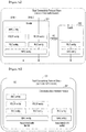
- FIG. 2a illustrates a dual connectivity protocol stack in the Master eNB (MeNB) and the Secondary eNB (SeNB) for no-split data radio bearer implementation wherein the DRB1 handled by MeNB 101 and DRB2 handled by SeNB 102 are split at the serving gateway (SGW) in the core network, according to embodiments as disclosed herein.
- FIG. 2b illustrates dual connectivity protocol stack implementation in the UE 103 for no-split data radio bearer implementation wherein there is dual stack one associated with the MeNB 101 and the other associated with the SeNB 102, according to embodiments as disclosed herein.
- the method Based on the dual connectivity protocol stack implementation in the UE 103, the MeNB 101 and the SeNB 102, the method provides various embodiments for handling RLF on the data bearer between the UE 103 and the SeNB 102 by various entities of the protocol stack and is described later.
- FIG. 2a depicts the dual connectivity protocol stack in accordance with the 3GPP specifications for no-split bearer implementations where a Radio Resource Control (RRC) entity is present only in the MeNB 101.
- the dual connectivity protocol stack in the MeNB 101 includes a Packet Data Control Protocol (PDCP) entity, a Radio Resource Control (RLC) entity, a Medium Access Control (MAC) entity handling a data radio bearer (DRB 1) established between the PCell 104 and the UE 103.
- the dual connectivity protocol stack in the SeNB 102 does not include the RRC entity as the MeNB 101 is the mobility anchor.
- the dual connectivity protocol stack for the SeNB 102 comprises the PDCP entity, the RLC entity and the MAC entity for handling data radio bearer (DRB 2) between the SCell 105 and the UE 103.
- FIG. 2b depicts the dual connectivity protocol stack in accordance with the 3GPP specifications for no-split bearer implementations in the UE 103.
- the UE 103 includes a communication interface module 201 comprises two set of protocol stacks, one each for the data radio bearer associated with the MeNB 101 (DRB 1) and the data radio bearer associated with the SeNB 102 (DRB 2).
- the protocol stack in the UE 103 corresponding to the MeNB 101 and the SeNB 102 replicates the corresponding protocol stacks in the MeNB 101 and SeNB 102.
- a single RRC entity is common for the protocol stack associated with the MeNB 101 and the protocol stack associated with the SeNB 102 for no-split bearer implementation.
- the communication interface module 201 allows the UE 103 to communicate with nodes of the wireless network 100 such as the MeNB 101 and the SeNB 102. It is understood to a person of ordinary skilled in the art that the UE 103 comprises a plurality of other modules for carrying out plurality of functions are not described for brevity.
- UP User Plane
- MeNB 101 belongs to MeNB 101 and another belongs to SeNB 102 as shown in FIG 2b .
- the primary stack has configuration which is associated with the MeNB or to eNB which has PCell 104 configured.
- the secondary stack has the configuration associated with the SeNB or SCell 105 which does not belong to eNB which has PCell 104.
- the other way to configure these two user plane stacks is through the primary PDCP entity and the secondary PDCP entity as split is above PDCP level (in the core network level as shown in FIG 2a ).
- the UE 103 can follow the legacy procedure if error indications are reported by lower layers of the user plane stack (the MAC entity or the RLC entity associated with MeNB) for the one or more data radio bearers which belong to primary PDCP entity.
- the new procedure for handling radio link problem proposed in the invention has to be followed if error indications are reported by lower layers of the user plane stack (the MAC or the RLC entity associated with MeNB) for the one or more data radio bearers which belongs to secondary PDCP entity or the common PDCP entity.
- FIG. 3a illustrates dual connectivity protocol stack in the MeNB and the SeNB for split data radio bearer implementation wherein the DRB 1 is handled by MeNB 101 and the DRB 2 also handled by MeNB 101 is split at the MeNB in the radio access network, according to embodiments as disclosed herein.
- FIG. 3b illustrates the dual connectivity protocol stack in the UE for split data radio bearer implementation, according to embodiments as disclosed herein. Based on the dual connectivity protocol stack implementation in the UE 103, the MeNB 101 and the SeNB 102 the method provides various embodiments for handling RLF on data bearer between the UE 103 and the SeNB 102 at various entities of the protocol stack and are described in later part of the description.
- FIG. 3a depicts the dual connectivity protocol stack in accordance with the 3GPP specifications for split bearer implementations in the MeNB 101. Based on the dual connectivity protocol stack implementation in the UE 103, the MeNB 101 and the SeNB 102 the method provides various embodiments for handling RLF on data bearer between the UE 103 and the SeNB 102 by various entities of the protocol stack and are described later in later part of the description.
- the RRC entity resides only in the MeNB 101 for dual connectivity. Also, for split bearer implementation as shown in FIG. 3a the RRC entity resides only in the MeNB 101 since it is the mobility anchor. However in the MeNB 101 there are two separate PDCP entities each associated with the DRB 1 and DRB 2 handled by the MeNB. The DRB 1 is not split whereas the DRB2 is split in the MeNB 101 below the PDCP entity and some PDCP PDUs of DRB 2 are handled by the user plane protocol stack of MeNB 101 and some PDCP PDUs of DRB 2 are handled by the user plane protocol stack of the SeNB 102 respectively.
- the DRB 2 is split below the PDCP entity residing in the MeNB 101 and hence the PDCP entity handling DRB2 is a common PDCP entity corresponding to the MeNB 101 and SeNB 102.
- protocol stack of the SeNB 102 includes the RLC entity and the MAC entity for DRB 2.
- the MAC entity in MeNB 101 is common entity handling DRB1 and split DRB 2 whereas the RLC entity is independent for DRB 1 and split DRB2.
- FIG. 3b depicts dual connectivity protocol stack in accordance with the 3GPP specifications for split bearer implementations in the UE 103.
- the communication interface module 201 in the UE 103 includes two set of protocol stack.
- the protocol stack for the data radio bearer associated with MeNB 101 includes the RRC entity, the PDCP entity, the RLC entity and the common MAC entity.
- the protocol stack for the split data radio bearer associated with the MeNB 101 is handled by the PDCP entity also associated with the SeNB 102 called the common PDCP entity.
- the protocol stack associated with the SeNB 102 for handling the split data radio bearer associated with SeNB 102 (DRB 2) includes the RLC entity, the MAC entity and the common PDCP entity.
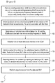
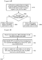
- FIG. 4 is a flow diagram illustrating a method 400 for configuring the UE for dual connectivity mode of operation and subsequently initiating a random access procedure on the SeNB during an addition or a replacement of a Secondary Cell (SCell) of the SeNB. Further, a Radio Link problem, if occurred, on a data radio bearer of the SCell of the SeNB is handled, according to embodiments as disclosed herein.
- SCell Secondary Cell
- the method 400 explains the process of addition or replacement of only one SCell associated with SeNB 102 for ease of understanding. However, it is understood by a person having ordinary skill in the art that with suitable modifications the method can be applied for addition or replacement of plurality of SCells of SeNB 102, when the UE 103 is within the coverage of those respective SCells.
- the UE 103 currently served by only the PCell 104 associated with the MeNB 101 and served by a carrier frequency from the first set i.e in this case the first frequency
- the SCell 105 is provisioned with PUCCH resource configuration.
- the UE 103 is currently being served by the PCell 104 from the MeNB 101 and the SCell 105 with PUCCH configuration from the SeNB 102.
- the SCell 105 which is the current serving SCell of the SeNB 102 can be replaced with another SCell (for example, the suitable candidate SCell such as SCell 106 provisioned with PUCCH resources) which may belong to the same SeNB 102 or some other SeNB.
- the replacement of SCell 105 may be due several reasons like the UE is losing coverage of SCell 105 or the PUCCH resource load on the SCell is high.
- the UE 103 can be additionally served by a SCell assigned with a different frequency from the second set of frequencies by adding the SCell 106 of SeNB 102.
- the SCell 106 to be added is a SCell without PUCCH configuration.
- the method allows modification of the configuration of the SCell of the SeNB that currently serves the UE 103.
- the modification indicates replacement of the current serving SCell of the UE with the new SCell belonging to the same SeNB or replacement of the current group of serving SCells of the UE with one or more SCells belonging to a different SeNB through a new configuration received in the RRC connection reconfiguration message.
- replacement and modification can be used interchangeably wherein replacement means removal of the old SCell and addition of the new SCell.
- SCell modification where the current SCell of the UE associated with the SeNB is not replaced with any other SCell through a new configuration received in the RRC connection reconfiguration message, then the SCell configuration is removed and the UE is said to be removed with the SeNB configuration and continue to operate in single connectivity mode of operation with the MeNB.
- the steps for the replacement of the SCell are similar to the steps for the addition of the SCell and may involve suitable modifications as understood by a person having ordinary skill in the art.
- the proposed method describes the steps with reference to addition of the SCell for brevity.
- the method 400 configures the UE 103 to receive a configuration in downlink direction from the PCell 104 served on the first frequency of the MeNB 101 for addition of the SCell of SeNB 102 associated with the second serving frequency.
- the configuration is received by the UE 103 in the RRC message for adding the SCell (for example SCell 105 of the SeNB). Whenever, the added SCell 105 is the only SCell associated with the SeNB 102, the SCell 105 is provisioned with PUCCH resource configuration.
- SCell for example SCell 105 of the SeNB
- the provisioning of the PUCCH resources for the SCell 105 to be added is included in the RRC connection reconfiguration message. Further, the method 400 configures the UE 103 to perform plurality of steps to activate the plurality of SCells that have been added based on the RRC connection reconfiguration message. The steps the UE 103 performs to activate the plurality of SCells are based on whether the added SCell is the SCell with PUCCH configuration or the SCell without the PUCCH configuration.
- the method 400 configures the UE 103 to establish one or more entities such as the PDCP entity, the RLC entity and the MAC entity of user plane protocol stack associated with the SeNB 102 based on the configuration parameters received in the RRC connection reconfiguration message.
- the method 400 configures the UE 103 to send the RRC reconfiguration complete message in the uplink direction to the PCell 104 of the MeNB 101 to indicate comprehending of the SeNB configuration in the UE.
- the steps are described later in FIG. 5 and FIG. 6 .
- the added SCell 105 is the only SCell associated with the SeNB 102 and is provisioned with PUCCH resource configuration so the SCell 105 is activated in the UE 103 based on the RRC reconfiguration message received to add the SCell 105.
- the method configures the UE 103 to initiate the random access procedure on the SCell 105 of the SeNB 102 to achieve uplink synchronization with the SeNB 102.
- the method configures the UE 106 to identify whether the added SCell is the SCell with PUCCH configuration based on whether the RRC connection re configuration message received by the UE 103 includes provisioning of the PUCCH resources on the SCell to be added.
- the method configures the UE 103 to autonomously initiate the a contention based random access on the SeNB 102 associated with the SCell 105.
- the UE 103 can be configured to initiate a contention based random access on SeNB 102 when the added SCell 105 is with PUCCH configuration.
- the UE 103 can be configured to initiate a contention free random access on SeNB when the added SCell 105 is with PUCCH configuration.
- the added SCell such as SCell 106 is the SCell without the PUCCH configuration.
- more than one SCell is added (a group of SCells belonging to the SeNB 102) through the RRC reconfiguration message, then at most one SCell 105 is provisioned with PUCCH resource configuration whereas the other added SCells like SCell 106 are without PUCCH resources.
- the method 400 configures the UE 103 to initiate the contention free random access on the SeNB 102 associated with the SCell 106.
- the contention based random access is autonomously performed by the UE 103 for uplink synchronization towards the activated SCell 105 with the PUCCH configuration.
- the contention based random access is autonomously performed by the UE 103 towards the SCell 105 with the PUCCH configuration of the SeNB 102 to achieve uplink synchronization for the first time when the SCell 105 is added and activated.
- the autonomous initiation of the contention based random access is triggered due a downlink data arrival notification or an uplink data transmission towards the SeNB 102.
- the method 400 configures the UE 103 to send status of communication link between the UE 103 and the SCell 105 to MeNB 101.
- the method 400 configures the UE 103 to send a success cause value in the status to the MeNB 101.
- the method 400 configures the UE 103 to send a failure cause value in the status to the MeNB 101.
- the status of the contention based random access procedure on the activated SCell with PUCCH configuration can be sent in a RRC connection re-configuration complete message or a new dedicated RRC message. If the status is sent in a new dedicated RRC message then the RRC connection reconfiguration complete message is sent after addition of the SCell as explained at step 401, otherwise the RRC connection reconfiguration complete message is sent at step 403.
- the method 400 configures the UE 103 to establish one or more data radio bearers on the SCell 105 of the SeNB 102.
- the one or more data radio bearers are established based on a data radio bearer configuration received in the RRC connection reconfiguration message received at step 401.
- the method 400 configures the UE 103 to perform data exchange on the established one or more data radio bearers. While data is exchanged on one or more data radio bearers between the UE 103 and SeNB 102, the uplink synchronization is performed towards the activated SCell 105 with the PUCCH configuration when the uplink synchronization is lost by the UE 103 and there is a trigger for a downlink data arrival or an uplink data transmission.
- the uplink synchronization can be lost by the UE 103 due to expiry of associated timing advance timer (TAT).
- TAT timing advance timer
- the method 400 configures the UE 103 to identify the radio link problem on the data radio bearer established on the SCell 105 of the SeNB 102 and detect the RLF after confirming the radio link problem.
- the identified radio link problem can be the Random Access Channel failure (RACH failure) on the SCell 105 with PUCCH configuration identified by the MAC entity in the UE 103, when the contention based random access procedure on the SCell 105 is unsuccessful.
- RACH failure Random Access Channel failure
- the identified radio link problem is the Radio Link Control error (RLC error) identified by the RLC entity associated with SeNB 102 in the UE 103 on the uplink data radio bearer established on the SCell 105.
- RLC error Radio Link Control error
- the method configures the UE 103 to identify the RLC error on any other SCell of SeNB 102 on which uplink data radio bearer is established where the SCell serving the UE 103 is a SCell without PUCCH resources like SCell 106.
- the method 400 configures the UE 103 to confirm the identified radio link problem as Radio Link Failure (RLF) and report the RLF to the MeNB 101 in uplink direction on the serving frequency (first serving frequency) assigned to the PCell 104 for serving the UE 103.
- the reporting of RLF includes preparing and sending the RLF report to the MeNB 101.
- the contents of the RLF report are based on whether detected RLF is the RACH failure or the RLC error.
- the RLF report includes one or more parameters such as connectionFailureTypeField set to RLF-SeNB, cause value field set to the RLC error or the RACH failure and so on which are described later in FIG. 7 and FIG. 8 .
- the parameters in the RLF report indicate the MeNB 101 about the type of RLF encountered by the UE 103 when served by the serving frequency (second serving frequency) assigned to the SCell associated with the SeNB 102.
- the RLF report is sent to the MeNB 101 in the new dedicated RRC message, an existing RRC message, a new Medium Access Control Element (MAC CE), a new Packet Data Control Protocol (PDCP) Protocol Data Unit (PDU) or similar suitable messages.
- MAC CE Medium Access Control Element
- PDCP Packet Data Control Protocol
- PDU Protocol Data Unit
- the reporting of the detected RLF to the MeNB 101 is performed at the PDCP entity level of the UE 103 using the new PDCP PDU and is described in detail in FIG. 11 .
- the reporting of the encountered RLF-SeNB to the MeNB 101 by the UE 103 further refrain the UE 103 from initiating a RRC connection re-establishment procedure towards the MeNB 101.
- the UE 103 therefore continues to perform data exchange with the MeNB 101 for the data radio bearers established on the MeNB even though a RLF was detected on the SCell of the SeNB 102.
- refraining to initiate the RRC connection reestablishment procedure towards the MeNB 101 when RLF-SeNB is encountered the service interruption is avoided.
- the UE 103 can follow the legacy procedure if error indications are reported from lower layers such as the MAC entity or the RLC entity in the UE 103 associated with the MeNB 101.
- the legacy procedure involves the RRC connection re-establishment procedure triggered by the RRC entity in the UE 103.
- UE 103 In the dual connectivity mode operation of UE 103 in the wireless network 100 there is need to identify the SCell association in UE by the RRC entity for handling RLC error reported from lower layers of the user plane stack.
- the UE 103 can follow the legacy procedure (for RRC connection re-establishment) if the RLC error occurs on data radio bearers established on SCell associated with MeNB which also has PCell. If eNB handling SCell is different from the eNB handling PCell (in case of inter-eNB carrier aggregation) and when RLC error reported from lower layer then UE 103 cannot reuse the legacy procedure as it will lead to interruption of service on the PCell 104.
- the UE 103 after sending the RLF report to the MeNB 101 the UE 103 suspends the RLC entity and the PDCP entity which handles one or more data radio bearers associated with the SeNB 102. Further, the UE 103 resets the MAC entity associated with the SeNB 102 and stops monitoring of the PDCCH and stops uplink transmissions towards the SeNB 102.
- the UE 103 after sending the RLF report to the MeNB 101 the UE 103 suspends the RLC entity which handles data radio bearer associated with the SeNB 102 while maintaining operation of the common PDCP entity handling the split data radio bearer associated with MeNB 101 and SeNB 102. This ensures that the on-going service on the MeNB 101 is unaffected. Further, the UE 103 resets the MAC entity associated with the SeNB 102. The resetting of the MAC entity enables stopping monitoring of the PDCCH and stopping the uplink transmissions towards the SeNB.
- the reporting of the RLF-SeNB to the MeNB 101 and suspending the protocol stack associated with the SeNB enables the UE 103 to prevent interruption of data on the MeNB 101, effectively preventing any loss of data on the MeNB 101.
- the method 400 configures the UE 103 to perform steps to recover from the RLF-SeNB encountered by the UE 103.
- the method configures the UE to receive a message from the MeNB 101 in response to the RLF report sent by the UE 103.
- the method 400 configures the UE 103 to receive the response message to the RLF report from the RRC entity of the MeNB 101.
- the response is received in the RRC connection reconfiguration message.
- the response to the RLF report indicates the recovery actions to be performed by the UE 103 to recover from the RLF-SeNB.
- the recovery actions include configuring the UE 103 to re-establish the data radio bearer associated with the SeNB 102 based on radio bearer re-configuration parameters received in the RRC connection re-configuration message in downlink direction from the PCell 104 of the MeNB 101.
- the RRC connection re-configuration message includes replacement of the SCell associated with the SeNB 102 or complete removal of the SeNB configuration.
- the method 400 upon reception of the RRC connection reconfiguration message, configures the UE 103 to perform the random access procedure for uplink synchronization towards one of the suitable candidate SCell of the SeNB 102 or a suitable SCell of another candidate SeNB.
- the replaced suitable SCell is a SCell with the PUCCH configuration on which the data radio bearer associated with the SeNB 102 for which RLF was encountered can now be re-established.
- the RRC connection reconfiguration message includes radio reconfiguration parameters indicating the UE 103 to perform one or more actions (recovery actions) including but not limited removing configuration of the suspended data radio bearer associated with the SeNB 102 and applying the new configuration received in the RRC connection reconfiguration message for re-establishing the data radio bearer.
- one or more actions include but are not limited to replacing, in the general case plurality of SCells and in a particular case the SCell 105 provisioned with the PUCCH resources with any suitable candidate SCell of the SeNB 102 or any other suitable one or more SCells of any other suitable candidate SeNB in the wireless network 100.
- recovery action includes configuring the UE 103 to deactivate the SCell 105 on which the RLF was detected.
- recovery action includes configuring the UE 103 to remove the configuration associated with the SeNB 102 when the re-configuration parameters received in the RRC connection re-configuration message do not include either a suitable replacement candidate SCell or a another suitable candidate SeNB. In this case the data radio bearers are then re-established on the MeNB 101.
- the process associated with removing of the configuration associated with the SeNB 102 include removing the PDCP entity, the RLC entity and the MAC entity of the UE 103 associated with the SeNB 102 for the no-split radio bearer implementation of dual connectivity protocol stack.
- the process associated with removing of the configuration associated with the SeNB 102 include removing the RLC entity and the MAC entity of the UE 103 associated with the SeNB 102.
- method 400 configures the UE 103 to remove configuration of one or more suspended data radio bearer and apply new configuration for re-establishing one or more suspended data radio bearer either on suitable candidate SCell of SeNB 102 or any other suitable candidate SeNB or the MeNB 101 itself.
- the one or more suspended data radio bearer may be re-established on the PCell 104 of the MeNB 101 or a candidate serving cell of the MeNB (for example SCell 107 of the MeNB 101) based on the radio bearer re-configuration parameters received in the RRC connection re-configuration message in downlink direction from the MeNB 101.
- the suspended one or more data radio bearer is re-established after removing current configuration of the suspended data radio bearer and applying new configuration received in the RRC connection reconfiguration message for re-establishing the suspended data radio bearer.
- the suspended one or more data radio bearer is resumed by replacing the SCell 105 with the PUCCH configuration with the suitable candidate SCell of the SeNB 102 or the suitable SCell of any other suitable candidate SeNB.
- the resuming of data radio bearer includes re-establishing the RLC entity and the PDCP entity in the UE 103 for the no-split radio bearer implementation of dual connectivity protocol stack.
- the resuming of data radio bearer includes re-establishing the RLC entity in the UE 103.
- the replaced suitable candidate SCell is provisioned with PUCCH resources based on the PUCCH resource configuration included in the RRC connection re-configuration message in downlink direction from the MeNB 101.
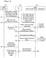
- FIG. 5 is an example sequence diagram illustrating the initiation of the random access procedure after the addition or the replacement of the SCell with a Physical Uplink Control Channel (PUCCH) configuration, according to embodiments as disclosed herein.
- the FIG. 5 depicts the PCell 104 of the MeNB 101, the UE 103 and the SeNB 102 with the SCell 105 with PUCCH configuration.
- the UE 103 performs the contention based random access procedure towards the SeNB 102 after the addition of the SCell 105 or replacement of the SCell with PUCCH configuration based on the received RRC connection reconfiguration message.
- the steps for replacement of the current serving SCell provisioned with PUCCH configuration with another suitable SCell with PUCCH configuration are similar to steps shown for addition or may include suitable modifications and are not repeated for brevity.
- the UE receives (501) the RRC connection reconfiguration message for either addition or replacement of SCell with PUCCH configuration associated with the SeNB 102.
- the UE 103 comprehends with the configuration received in the RRC connection reconfiguration message by applying the configuration and adding the SCell 105 associated with SeNB 102 provisioned with PUCCH configuration assigned with a second serving frequency (a frequency from a second set of serving frequencies).
- the serving frequency of SCell 105 is different from the serving frequency of PCell 104 since the PCell serving is assigned from the first set of serving frequencies.
- the RRC connection reconfiguration message provisions one or more data radio bearer configurations for one or more data radio bearers to be established on the SCell 105 with the PUCCH configuration, configuration parameters for establishing lower layer entities and a Temporary C-RNTI to be used for the second eNB. Further, the UE 103 after adding the SCell 105 based on the RRC connection reconfiguration message received from the PCell 104 sends (502) a RRC connection reconfiguration complete message in uplink direction to the PCell 104 of MeNB 101 to indicate that the UE 103 comprehends to the configuration.
- the MeNB 101 may optionally provide the Temporary C-RNTI (T-CRNTI) to the UE 103 in the MAC CE.
- the MeNB 101 also informs addition and activation of the SCell in the UE 103 to the SeNB 102 and forwards the T-CRNTI provided to the UE along with a SAE Temporary Mobile Subscriber Identity (S-TMSI) of the UE on the X2 interface.
- S-TMSI Temporary Mobile Subscriber Identity
- a new Information Element can be added by PCell 104 along with data radio bearer information.
- the PCell 104 could add new IE along with bearer information during set up of data radio bearer whether it belongs to MeNB 101 or SeNB 102.
- the IE for data radio bearer information can be defined associated with the MeNB 101 or primary eNB or first eNB where primary eNB is the eNB which has the PCell 104.
- the IE for data radio bearer information can be defined associated with the SeNB 102 or secondary eNB or second eNB.
- Another way to define the IEs can be based on master or slave IEs, where master IE belongs to MeNB 101 and slave IE can be associated with the SeNB 102. This enables the UE to identify whether particular set of bearers belongs to MeNB or SeNB.
- the data radio bearer configuration included in the RRC reconfiguration message from the PCell includes separate information elements (IEs) for the one or more data radio bearers to be established on the MeNB and the SeNB.
- the PCell 104 may include new IE primary-drb-ToAddModList and secondary- drb-ToAddModList.
- the primary-drb-ToAddModList is the data radio bearer configuration which belongs to MeNB 101 or to the first eNB to which the PCell 104 belongs and includes the radio bearer identity and mapping with the EPS bearer.
- the secondary-drb-ToAddModList is the data radio bearer configuration which belongs to SeNB 102 or to the second eNB which the SCell 105 and/or 106 belongs and includes the radio bearer identity and mapping with the EPS bearer.
- the UE 103 then activates the SCell 105 within the UE 103 based on the received RRC connection reconfiguration message (501). For the first time when the SCell 105 is added and activated, then on activation of the SCell 105, the UE 103 (specifically the MAC entity associated with SeNB 102 within the UE 103) autonomously initiates the contention based random access procedure towards the activated SCell 105 for uplink synchronization towards the SeNB 102.. The autonomous initiation of the contention based random access is triggered due a downlink data arrival notification or an uplink data transmission towards the SeNB 102.
- the contention based random access procedure is performed by the UE 103 by initiating transmission (503) of a randomly selected Random Access (RA) preamble on a determined Physical Random Access Channel (PRACH) resource of the SCell 105 associated with SeNB 102. Further, the UE 103 monitors a common search space of a Physical Downlink Control Channel (PDCCH) region of the SCell 105 associated with SeNB 102 for reception of a Random Access Response (RAR) message. The UE 103 receives (504) the RAR message in downlink direction from the SCell 105 and the UE 103 decodes the RAR message using a Random Access Radio Network Temporary Identifier (RA-RNTI) associated with the determined PRACH.
- RA-RNTI Random Access Radio Network Temporary Identifier
- the UE 103 After decoding the RAR message received at step 504 the UE 103 receives an uplink grant, a random access preamble identifier, optionally a Temporary C-RNTI and uplink timing advance information in response to the RA preamble transmission at step 503.
- the uplink grant is then used by the UE 103 to send a message for contention resolution (message-3) and the uplink timing advance information is used for the uplink synchronization towards the SeNB 102.
- the UE 103 sends (505) a message for contention resolution (random access message-3) containing a UE identity for contention resolution in uplink direction based on the uplink grant provided in the RAR message (504).
- the UE identity may be the T-CRNTI either received in RRC connection reconfiguration message at step501 and/or the one received in RAR message at step504 or some other identity randomly selected by the UE.
- the UE 103 receives (506) a contention resolution message (random access message-4) in downlink direction from the SeNB 102 for resolving the contention by decoding the contention resolution message using the Temporary C-RNTI and receiving back the same UE identity sent by the UE 103 in the in the request message (random access message-3).
- the Temporary C-RNTI is received in the RRC reconfiguration message and/or the RAR message.
- the UE 103 After receiving the contention resolution message at step 506, the UE 103 completes the random access procedure successfully. There is a possibility that the after transmitting the RA preamble at step503 multiple times the UE does not receive the RAR message at step504. Depending on the success or failure of the random access procedure towards the SeNB 102 the UE 103 sends (507) the status of the random access procedure to the MeNB 101.
- the status of the random access procedure can be sent in a new dedicated RRC message or existing message.
- the status message sent at step 507 to the PCell 104 of MeNB 101 may be sent in a new dedicated RRC message.
- the transmission of RRC connection reconfiguration complete message is not done at step 502. In this case, the transmission of the RRC connection re-configuration message is delayed till the reception of the contention resolution message at step 506. In this case the UE 103 can send the status of the random access procedure in the RRC connection reconfiguration complete message at step 507.
- the status is provided using the cause value indicating success or failure of the random access procedure initiated by the UE 103 towards the SeNB 102. If the random access procedure is success, the success cause value is sent in the status. Further, the UE 103 sets a C-RNTI to the value of the Temporary C-RNTI received in the RRC connection reconfiguration message at step501 and/or in the RAR message at step 504 after the UE 103 successfully receives the contention resolution message at step (506.
- the C-RNTI is used by the UE 103 for the data exchange with the SeNB 102 and it is different from the C-RNTI allocated to the UE by the MeNB 101 for the data exchange with the MeNB 101.
- the UE 103 establishes one or more data radio bearers on the SCell 105 with the PUCCH configuration based on the data radio bearer configuration received in the RRC connection reconfiguration message at step501.
- the data radio configuration (secondary-drb-ToAddModList) includes a data radio bearer identity corresponding to the data radio bearer established on the SCell 105 with the PUCCH configuration associated with the SeNB 102.
- the data radio bearer identity is unique for data radio bearers established on the MeNB 101 and the SeNB 102 respectively.
- the UE 103 performs (508) data exchange on the established one or more data radio bearers using the C-RNTI which is set to value of the Temporary C-RNTI received in the RRC connection reconfiguration message at step 501 and/or in the RAR message at step 504 .
- the decoding of the Physical Downlink Shared Channel (PDSCH) scheduled by the SeNB on the second serving frequency associated with SCell 105 is done using C-RNTI associated with SeNB 102 and different from the C-RNTI associated with the MeNB 101.
- PDSCH Physical Downlink Shared Channel
- the UE 103 may initiate the contention based random access procedure when the UE 103 looses uplink synchronization towards the SCell with the PUCCH configuration and there is a trigger for either a downlink data arrival or an uplink data transmission.
- the UE follows steps 503 to step 506 of the random access procedure and depending on the status of the random access (RACH) procedure a status message is sent to the MeNB 101.
- the sending of the failure status of the RACH is mandatory whereas the sending of the success status of the RACH is optional.
- the RACH failure is detected as RLF and the step 507 of FIG 5 corresponds to step 406 of FIG 4 .
- the MeNB 101 invokes the recovery procedure as shown in step 407 of FIG 4 .
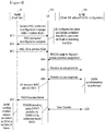
- FIG. 6 is an example sequence diagram illustrating the initiation of the random access procedure after the addition or the replacement of the SCell without the PUCCH configuration, according to embodiments as disclosed herein.
- the FIG. 6 depicts the PCell 104 of the MeNB 101, the UE 103 and the SeNB 102 with the SCell 106 without the PUCCH configuration.
- the UE 103 performs the contention free random access procedure after the addition of the SCell 106 without the PUCCH configuration when the UE 103 is already currently served by SCell 105 with PUCCH configuration associated with the SeNB 102.
- the time advance group (TAG) of the SCell 105 and SCell 106 is different then only the random access procedure can be performed on SCell 106. If based the RRC connection reconfiguration message (601) while adding the SCell 106 if the configuration indicates the SCell 106 belongs to the same TAG as that of SCell 105 then there is no need to perform the random access procedure on SCell 106. In this case based on the random access procedure on the SCell 105 (explained in FIG 5 ) the uplink timing information received in RAR message (504) is also applied for SCell 106 for achieving uplink synchronization.
- the FIG. 6 considers an example when the SCell 105 with PUCCH configuration and the SCell 106 without PUCCH configuration belong to different TAG.
- the SCell 106 to be added is the SCell without PUCCH resources and hence after addition is performed the initiation of contention free random access procedure on the SeNB 102 associated with the SCell 106 is explained in the following.
- the UE 103 receives (601) the RRC connection reconfiguration message indicating addition of the SCell 106 without PUCCH resources associated with the SeNB 102.
- the UE 103 comprehends (applies the configuration) and adds the SCell 106 assigned with one of the serving frequency from the second set of frequencies based on the received RRC connection reconfiguration message.
- the RRC connection reconfiguration message provisions data radio bearer configuration for one or more data radio bearers to be established on the SCell without the PUCCH configuration, configuration parameters for establishing lower layer entities and the Temporary C-RNTI to be used for the SeNB 102.
- the serving frequency of SCell 106 is different from the serving frequency of SCell 105 even though they are assigned from the second set of serving frequencies.
- the UE 103 establishes the PDCP entity or the RLC entity of the user plane protocol stack associated with the SeNB 102 based on the configuration parameters received in the RRC connection reconfiguration message.
- the UE 103 sends (602) the RRC connection configuration complete message in uplink direction to the PCell 104 of MeNB 101 to indicate that the UE 103 comprehends to the configuration.
- the SCell 106 without the PUCCH configuration is activated in the UE 103 only after reception of MAC CE from the MeNB 101.
- the MAC CE to activate the SCell 106 can also be received from the SCell 105 of the SeNB 102.
- the UE 103 receives (603) the MAC CE to activate the SCell 106.
- the SCell is activated by the UE 103 for establishment of one or more data radio bearers on SCell 106 based on the data bearer configuration parameters received in RRC connection reconfiguration message at step 601.
- the data radio bearer configuration parameters included in the RRC reconfiguration message from the PCell 104 includes secondary-drb-ToAddModList for one or more data radio bearers and the unique identity of respective bearers to be established on the SCell 106 of the SeNB 102.
- the contention free random access procedure may be performed on the activated SCell 106 when the TAG of SCell 106 is different from the TAG of the SCell 105 and initiated with the transmission of PDCCH order from the wireless network node.
- the SeNB 102 sends (604) a PDCCH order on the current serving SCell 105 to the UE 103 to allow the UE to initiate the contention free random access towards the SeNB 102.
- the MeNB 101 can send the PDCCH order to the UE 103 on the current serving PCell 104 to allow the UE to initiate the contention free random access procedure towards the SeNB 102.
- the UE 103 is provided with a dedicated Random Access (RA) preamble that can be used for transmission towards the activated SCell 106 of the SeNB 102 on a determined PRACH resource.
- RA Random Access
- the UE 103 After reception of the PDCCH order, the UE 103 initiates (605) transmission of the assigned RA preamble (dedicated RA preamble) towards the SCell 106 of the SeNB 102 on the determined PRACH resource.
- the UE 103 monitors the common search space of PDCCH region of the SCell 105 with PUCCH configuration associated with SeNB 102, which is the currently serving SCell of the UE 103, for the RAR message reception (606) from the SeNB 102.
- the UE 103 decodes the RAR message received in downlink direction from SeNB 102 using the RA-RNTI associated with the PRACH.
- the RAR message includes an uplink grant and/or an uplink timing advance information in response to the assigned RA preamble transmission.
- the UE 103 completes the random access procedure successfully. There is a possibility that the random access procedure may fail especially during step 605 and step 606 where after transmitting RA preamble at step 605 multiple times the UE does not receive RAR message at step 606.
- the UE 103 further, sends (607) status of the random access procedure to the MeNB 101 in the RRC connection re-configuration complete message or the new dedicated RRC message indicating the success and failure cause value.
- the UE 103 After successful completion of contention free random access procedure on SCell 106 of SeNB 102, the UE 103 establishes one or more data radio bearers on the activated SCell 106 based on the data radio bearer configuration received in the RRC connection reconfiguration message at step 601. Further, the UE 103 performs (608) data exchange on the established data radio bearers wherein the decoding of the Physical Downlink Shared Channel (PDSCH) scheduled by the SeNB on the second serving frequency associated with SCell 106 is done using the C-RNTI allocated to the UE 103 during previous contention based random access procedure towards the SCell 105 of the SeNB 102.
- PDSCH Physical Downlink Shared Channel
- FIG. 7 is an example sequence diagram illustrating handling of a Random Access Channel (RACH) failure, according to the embodiments as disclosed herein.
- the FIG. 7 depicts the MeNB 101 with the PCell 104, the SeNB 102 with the SCell 105, the UE 103 with the RRC entity and the MAC entity associated with SeNB.
- the FIG. 7 depicts the UE 103 being configured for dual connectivity mode of operation wherein the UE 103 is served by two cells with an established data radio bearer mapped to the EPS Bearer 1 701 on the PCell 104 of the MeNB 101 assigned with a first serving frequency.
- Another data radio bearer mapped to the EPS Bearer 2 702 is established on the SCell 105 with PUCCH configuration of SeNB 102 assigned with the second serving frequency.
- the uplink synchronization is performed towards the activated SCell 105 with the PUCCH configuration when the uplink synchronization is lost by the UE 103 and there is a trigger for a downlink data arrival or an uplink data transmission for the data radio bearer 702.
- the uplink synchronization can be lost by the UE 103 due to expiry of timing advance timer (TAT) associated with the TAG of the SCell 105.
- TAT timing advance timer
- the UE 103 performs (703) preamble transmission towards the SeNB 102 (This step is same as step 503 of FIG 5 ).
- the MAC entity of the UE 103 checks whether the preamble transmission counter exceeds a threshold preamble transmission count. If it is determined that the preamble transmission counter is within the pre-defined preamble transmission count, then the random access procedure continues with step 504, 505 and 506 of FIG 5 and is completed successfully. However, if it is determined that the preamble transmission counter exceeds the pre-defined preamble transmission count then the random access procedure is unsuccessful.
- the MAC entity in the UE 103 associated with the SeNB 102 indicates (704) the RRC entity of the UE 103 about a radio link problem due to the unsuccessful random access procedure by marking the radio link problem as the RACH failure.
- the RRC entity in the UE 103 detects the RLF and prepares the RLF report. Further, the RRC entity immediately sends 705 the RLF report concerning the SeNB 102 to the MeNB 101 with RLF cause value as RACH failure. (This step is same as step 507 of FIG 5 ).
- the RLF report prepared by the RRC entity of the UE 103 includes setting the connectionFailureType field to the RLF-SeNB and setting the cause value field to the RACH failure. Further, the RLF report includes measurement results of one or more serving cell of the SeNB 102 tagged with respective Physical Cell Identity (PCI) if the measurement results are available. The measurement results are based on measurements collected up to an instant the UE detects the radio link problem.
- PCI Physical Cell Identity
- the RRC entity in the UE 103 refrains from initiating the RRC connection re-establishment procedure towards the PCell 104 of the MeNB 101. This allows the UE 103 to avoid disruption of the ongoing service on the PCell 104.
- the recovery actions performed by the UE 103 to recover from the encountered RLF after reporting the RLF are already described in FIG. 4 and are not repeated for brevity.
- the RRC entity in UE 103 keeps the data radio bearer mapped to the EPS Bearer 1 (706) established and suspends the data radio bearer mapped to EPS Bearer 2 (707).
- the RRC entity of the UE keeps the configuration associated with the SeNB 102 until it receives (708) a new configuration in the RRC connection reconfiguration message in response to the RLF report sent in step 705.
- the UE removes the SeNB configuration and re-establishes the data radio bearer handled by SCell 105 on the PCell 104 of the MeNB 101.
- the recovery actions performed by the UE 103 to recover from the encountered RLF may be based on several other possible reconfiguration parameters as already described in FIG. 4 and are not repeated for brevity.
- the RRC entity in the UE 103 resumes the data radio bearer mapped to the EPS Bearer 2 (709) on PCell 104 of the MeNB 101.
- FIG. 8 is an example sequence diagram illustrating handling of a Radio Link Error (RLC) error, according to the embodiments as disclosed herein.
- the FIG. 8 depicts the MeNB 101 with the PCell 104, the SeNB 102 with one or more SCells such as SCell 105 with PUCCH configuration and SCell 106 without PUCCH configuration, the UE 103 with the RRC entity and the RLC entity associated with SeNB 102.
- the FIG. 8 depicts the UE 103 being configured for dual connectivity mode of operation wherein the UE 103 is served by two eNBs with an established data radio bearer mapped to the EPS Bearer 1 (801) on the PCell 104 of the MeNB 101 assigned with a first serving frequency.
- One or more data radio bearer mapped to the EPS Bearer (802) is established on SCell 105 with PUCCH configuration and SCell 106 without PUCCH configuration of SeNB 102 assigned with serving frequencies from the second set.
- the RLC entity of the UE 103 associated with the SeNB 102 identifies that maximum number of RLC retransmissions exceeds a predefined threshold for the uplink data radio bearer (EPS bearer 2) established towards the SeNB 102.
- the RLC entity of the UE 103 detects the radio link problem as the RLC error for the uplink data radio bearer established on SeNB 102.
- the RLC entity associated with the SeNB in the UE 103 indicates (803) the radio link problem due to the RLC error on the uplink data radio bearer by marking the radio link problem as the RLC error to the RRC entity in the UE 103.
- the RRC entity in the UE 103 detects the RLF and prepares the RLF report. Further, the RRC entity immediately sends the RLF report (804) with RLF cause value as RLC error for the SeNB 102.
- the RLF report prepared by the RRC entity of the UE 103 includes setting the connectionFailureType field to the RLF-SeNB and setting the cause value field to the RLC error. Further, the RLF report includes a logical channel identity of the uplink data radio bearer on which the RLC error is detected and measurement results of one or more serving cell of the SeNB 102 tagged with respective Physical Cell Identity (PCI) if the measurement results are available. The measurement results are based on measurements collected up to an instant the UE detects the radio link problem.
- PCI Physical Cell Identity
- the RRC entity refrains from initiating the RRC connection re-establishment procedure towards the PCell 104 of the MeNB 101. This allows the UE 103 to avoid disruption of the ongoing service on the PCell 104.
- the recovery actions performed by the UE 103 to recover from the encountered RLF after reporting the RLF are already described in FIG. 4 and are not repeated for brevity.
- the RRC entity in UE 103 keeps the data radio bearer mapped to the EPS Bearer 1 (805) established and suspends the data radio bearer mapped to EPS Bearer 2 (806).
- the RRC entity of the UE keeps the configuration associated with the SeNB 102 until it receives (807) a new configuration in the RRC connection reconfiguration message in response to the RLF report sent in step 804.
- the UE 103 based on the RRC reconfiguration parameters received in the RRC connection reconfiguration message, the UE 103 removes the SeNB configuration and re-establishes radio bearer handled by SeNB 102 on the PCell 104 of the MeNB 101.
- the recovery actions performed by the UE 103 to recover from the encountered RLF may be based on several other possible reconfiguration parameters as already described in FIG. 4 and are not repeated for brevity.
- the RRC entity in the UE 103 resumes the data radio bearer mapped to the EPS Bearer 2 (808) on PCell 104 of the MeNB 101.
- FIG. 9 is a flow diagram illustrating a method for reporting of the radio link problem by a common PDCP entity of the UE when the radio link problem is identified between the UE and the SCell of the SeNB, according to embodiments as disclosed herein.
- the split data radio bearer is handled by the RLC entity associated with the SeNB in the UE 103 and the common PDCP entity associated with the MeNB 101 and the SeNB 102.
- the method 900 allows handling RLF at PDCP/RLC level for occurrence of RLF due to the RLC error when the split data radio bearer dual connectivity protocol stack is being implemented.
- the method 900 configures the UE 103 to detect the radio link failure between the UE 103 and the SCell of SeNB 102 and mark the identified radio link problem as RLC error, when the RLF is detected due to the RLC error.
- the RLC entity of the UE 103 identifies the RLC error on the uplink data radio bearer when maximum number of retransmissions exceeds a predefined threshold for the data radio bearer.
- the method 900 configures the UE 103 to mark the radio link problem as the RLC error.
- the method 900 configures the UE 103 to allow the common PDCP entity in the UE 103 to receive an indication from the RLC entity of the UE 103 associated with the SeNB 102 notifying the radio link problem. The indication is received from the RLC entity of the UE 103 after identifying the RLC error for the data radio bearer established in the uplink direction towards the SeNB 102 by the RLC entity of the UE 103.
- the method 900 configures the UE 103 to allow the common PDCP entity of the UE 103 to report the RLC error to the common PDCP entity residing in the MeNB 101.
- the common PDCP entity of the UE 103 prepares a PDCP status report that indicates status of PDCP PDUs received by the UE 103 for downlink data radio bearer associated with the SeNB 102 which is handled by the RLC entity of the UE associated with the SeNB 102.
- the downlink data radio bearer associated with the SeNB 102 is handled by the common PDCP entity associated with the MeNB 101and the SeNB 102.
- the method 900 configures the UE 103 to send the PDCP status PDU by the common PDCP entity in the UE 103 indicating the RLC error to the common PDCP entity in the MeNB 101 in the uplink direction on the first serving frequency served by the PCell 104.
- the method 900 configures the UE103 to utilize the reserved bit of the PDCP PDU that defines a PDU type for indicating the radio link problem indicating the RLC error.
- the method 900 configures the UE 103 to allow the common PDCP entity in the UE 103 to prepare the PDCP status report indicating status of PDCP PDUs received by the UE 103 for a downlink data radio bearer associated with SeNB 102.
- the common PDCP entity in the UE 103 report the PDCP status report the common PDCP entity residing in the MeNB when there is radio link problem in downlink and/or uplink data radio bearers handled by the RLC entity of the UE associated with the SeNB 102.
- the downlink and/or uplink data radio bearer is handled by the RLC entity of the UE 103 associated with the SeNB 102 and the common PDCP entity in the UE 103 associated with the MeNB 101 and the SeNB 102.
- method 900 may be performed in the order presented, in a different order or simultaneously. Further, in some embodiments, some actions, acts, blocks, steps, and the like may be omitted, added, modified, skipped, and the like without departing from the scope of the invention.
- FIG. 10a and Fig 10b are flow diagrams illustrating a method 1000a and 1000b respectively for performing a random access procedure on the MeNB and the SeNB using either a parallel random access or a sequential random access, according to embodiments as disclosed herein.
- the UE In the inter-eNB carrier aggregation when the UE is configured for dual connectivity mode of operation, the UE is allowed contention based random access procedure on the SCell with PUCCH configuration of the SeNB. Thus, there could be scenarios where the UE may be performing two random access procedures in parallel, one on the MeNB and another on the SeNB.
- the UE 103 may trigger the random access procedure (contention based random access on the SCell 105 with PUCCH configuration) on the activated SCell 105 associated with the SeNB 102 when the uplink synchronization towards the activated SCell 105 with the PUCCH configuration is lost by the UE 103 and there is a trigger for one of a downlink data arrival and an uplink data transmission.
- the uplink synchronization may be lost by the UE 103 due to expiry of associated timing advance timer (TAT).
- TAT timing advance timer
- the random access procedure may be ongoing or triggered on the PCell 104, thus two random access procedures are being performed by the UE 103 simultaneously or in parallel.
- the multiple options arising in above mentioned scenario are handled by the UE 103 as shown in method 1000a and method 1000b.
- the method 1000a configures the UE 103 to identify whether the random access procedure is ongoing on the PCell 104 of the MeNB 101 and the random access procedure is triggered on the SCell 105 with PUCCH configuration of the SeNB 102.
- the random access procedure on the SCell 105 of the SeNB 102 can be triggered by expiry of a Timing Advance Timer (TAT) running for the SCell or unavailability of the Scheduling Request (SR) resource for the UE 103 on the SCell.
- TAT Timing Advance Timer
- SR Scheduling Request
- the method 1000a configures the UE 103 to determine whether a pre-defined criterion for random access is satisfied.
- pre-defined criteria is the random access procedure on the SCell of SeNB 102 is delayed if trigger for the random access procedure on SCell is due to uplink data and the logical channel priority of the SCell is less than the PCell logical channel priority.
- Another criterion may be consideration of transmission power required to perform random access procedure and if it determined that there is sufficient transmission power headroom to perform random access procedure on both, the MeNB and the SeNB then the parallel random access is allowed.
- the pre-defined criteria may be that random access procedure ongoing on SeNB is contention free random access (on SCell without PUCCH resources) then the contention based random access on the PCell of the MeNB may be delayed.
- the method 1000a configures the UE 103 for the parallel random access procedure to be performed on the MeNB 101 and SeNB 102 respectively. If at step 1002a, it is determined that the predefined criteria for the random access is unsatisfied, then at step 1004a, the method 1000a configures the UE 103 to perform the sequential random access procedure.
- the sequential random access procedure allowed by the method 1000a and 1000b configures the UE 103 to complete the ongoing random access procedure on the PCell 104 of the MeNB 101 and delay the initiation of the triggered random access procedure on the SCell provisioned with the PUCCH resources of SeNB 102. This delay is allowed as the random access procedure on the PCell 104 of the MeNB 101 is very important to keep the radio link with the mobility anchor stable and not delaying any UE action triggered towards the PCell 104 of the MeNB 101. Further, the random access procedure on the SCell 105 of the SeNB 102 is performed after successful completion of random access procedure towards the PCell 104.
- the sequential random access approach reduces UE complexity. However, prioritization of the random access procedure on the PCell is based on the pre-defined criteria.
- method 1000a may be performed in the order presented, in a different order or simultaneously. Further, in some embodiments, some actions, acts, blocks, steps, and the like may be omitted, added, modified, skipped, and the like without departing from the scope of the invention.
- the method 1000b configures the UE 103 to identify whether the random access procedure is ongoing on the SCell 105 with the PUCCH configuration of the SeNB 102 and the random access procedure is triggered on the PCell 104 of the MeNB 101.
- the trigger for the random access procedure on the PCell 104 can be due to either expiry of a Timing Advance Timer (TAT) running for the PCell 104 or unavailability of a Scheduling Request (SR) resource for the UE 103 on the PCell 104.
- TAT Timing Advance Timer
- SR Scheduling Request
- the SCell on which the random access procedure is on-going can be the current serving SCell 105 provisioned with the PUCCH configuration.
- the method 1000b configures the UE 103 to determine whether the pre-defined criterion for random access is satisfied.
- the method 1000b configures the UE 103 for the parallel random access to be performed on the MeNB 101 and SeNB 102 respectively.
- the method 1000b configures the UE 103 perform random access procedure on MeNB 101 and the on-going random access procedure on the SCell 105 can be aborted whenever random access procedure is triggered on the PCell 104.
- the method 1000b configures the UE 103 to complete the ongoing random access procedure (if it is contention free random access) on SeNB 102 and delay the triggered random access procedure on the PCell 104 since it is expected the contention free random access will be completed with less delay compared to the contention based random access.
- method 1000b may be performed in the order presented, in a different order or simultaneously. Further, in some embodiments, some actions, acts, blocks, steps, and the like may be omitted, added, modified, skipped, and the like without departing from the scope of the invention.
- the UE can autonomously initiate random access procedure on SCell or first request the PCell to activate SCell and then initiate random access procedure.
- the UE is allowed to autonomously initiate contention based random access procedure on the SCell of the SeNB, if the concerned SCell is configured in the list of carriers for inter-eNB carrier aggregation by the PCell.
- the UE first requests the PCell to activate the SCell of the SeNB from the list of configured SCells. In response, the UE receives a MAC CE for activation of the concerned SCell.
- the PCell may send the PDCCH order. If the PDCCH order is received by the UE then it follows contention free random access procedure on SCell Otherwise, the UE initiates contention based random access procedure on the SCell.
- FIG. 11 is a flow diagram illustrating a method 1100 for SeNB-based reporting of the radio link problem identified between the UE and the SCell using CQI report and/or HARQ ACK/NAK received from the UE, according to embodiments as disclosed herein.
- the Channel Quality Indication (CQI) reports and Hybrid Automatic Repeat Request (HARQ) Acknowledge/Negative-Acknowledgment ACK/NAK indications for downlink data and measurements reports for the second serving frequency assigned to the SCell of SeNB 102 are sent to the SCell of SeNB.
- the proposed method configures the SeNB 102 to utilize the CQI reports and/or the HARQ ACK/NAK indications to detect the RLF between the UE 103 and SCells associated with the SeNB 102. Further the proposed method configures the SeNB 102 to report the RLF for the identified UE 103 to the MeNB 101.
- the method 1100 configures the SeNB 102 to receive CQI reports and/or HARQ ACK/NAK for downlink data scheduled to the UE 103 from UEs served by the SCells of the SeNB 102.
- the method 1100 configures the SeNB 102 to detect the radio link problem on the serving frequency (second serving frequency) associated with the SCell of the SeNB.
- the SeNB 102 can identify the radio link problem as a downlink RLF based the parameters including but not limited to the CQI reports and/or the HARQ ACK/NAK indications sent to the SeNB 102 by the UE 103.
- the method 1100 configures the SeNB 102 to report the downlink RLF to the MeNB 101 through the non-ideal backhaul (X2 interface).
- the method 1100 configures the SeNB 102 to report the downlink RLF to the MeNB 101 through the ideal backhaul, if the ideal backhaul exists between the MeNB 101 and SeNB 102.
- the report includes parameters including but not limited to the cause value field indicating the downlink RLF and a reconfiguration message to re-establish one or more data radio bearer handled by the SeNB 102.
- the method 1100 configures the MeNB 101 to send the RRC connection reconfiguration message on the first serving frequency served by the PCell 104 in downlink direction to the UE 103.
- the RRC connection reconfiguration message indicates the UE 103 to perform replacement of the SCell with the suitable candidate SCell of the SeNB 102 or the suitable SCell of a suitable candidate SeNB in the wireless network 100.
- the UE 103 is indicated to deactivate the second serving frequency associated with the SeNB 102 on which the RLF was detected and indicated to remove configuration associated with the SeNB 102.
- the recovery actions performed by the UE 103 to recover from the encountered RLF based on other possible reconfiguration parameters are already described in FIG. 4 and are not repeated for brevity.
- the embodiments disclosed herein can be implemented through at least one software program running on at least one hardware device and performing network management functions to control the elements.
- the elements shown in Figs. 1 , 2a , 2b , 3a , 3b , 5 , 6 , 7 and 8 include blocks which can be at least one of a hardware device, or a combination of hardware device and software module.
- a method for performing a Random Access procedure by a User Equipment (UE) in a wireless network comprising:performing configuration with a Primary Cell (PCell) of a first evolved Node B (eNB) served on at least one first serving frequency and at least one Secondary Cell (SCell) of a first evolved Node B (eNB) served on at least one first serving frequency;transmitting a Random Access (RA) preamble on a Physical Random Access Channel (PRACH) to one of the at least one SCell;receiving a Random Access Response (RAR) message on a Physical Downlink Control Channel (PDCCH) from the one of the at least one SCell; andtransmitting uplink data to the one of the at least one SCell.
- PCell Primary Cell
- SCell Secondary Cell
- RAR Random Access Response
- RA-RNTI Random Access Radio Network Temporary Identifier
- PUCCH Physical Uplink Control Channel
- RA-RNTI Random Access Radio Network Temporary Identifier
- RRC Radio Resource Control
- the UE is configured to:decode the RAR message using a Random Access Radio Network Temporary Identifier (RA-RNTI) associated with the PRACH;receive an uplink grant, a random access preamble identifier, a Temporary C-RNTI and uplink timing advance information in response to the RA preamble; send a request message containing a UE identity for contention resolution based on the uplink grant;receive response in a contention resolution message using the Temporary C-RNTI and receiving back the UE identity; and send a status of random access procedure to the first eNB.
- RA-RNTI Random Access Radio Network Temporary Identifier
- MAC CE Medium Access Control Element
- PUCCH Physical Uplink Control Channel
- RA-RNTI Random Access Radio Network Temporary Identifier
- a method for performing a Radio Link Failure procedure by a User Equipment (UE) in a wireless network wherein the UE is carrier aggregated with at least one first serving frequency served by the first eNB and at least one second serving frequency served by the second eNB, the method comprising:detecting a radio link failure on the second serving frequency; transmitting information on the radio link failure to the first eNB; andreceiving a Radio Resource Control (RRC) connection reconfiguration message from the first eNB.
- RRC Radio Resource Control
- the radio link failure is one of a Random Access Channel (RACH) failure indicating that a random access preamble transmission counter exceeds a pre-defined threshold and a Radio Link Control (RLC) error indicating that maximum number of RLC retransmissions towards the second eNB exceeds a predefined threshold.
- RACH Random Access Channel
- RLC Radio Link Control
- the information is transmitted using a Medium Access Control (MAC) message or using a RRC message.
- MAC Medium Access Control
- the information further comprise a logical channel identity of uplink data radio bearer on which the RLC error is detected.
- RRC Radio Resource Control
- radio link failure is one of a Random Access Channel (RACH) failure indicating that a random access preamble transmission counter exceeds a pre-defined threshold and a Radio Link Control (RLC) error indicating that maximum number of RLC retransmissions towards the second eNB exceeds a predefined threshold.
- RACH Random Access Channel
- RLC Radio Link Control
- the UE of clause 17, the information is transmitted using a Medium Access Control (MAC) message or using a RRC message.
- MAC Medium Access Control
- the information further comprise a logical channel identity of uplink data radio bearer on which the RLC error is detected.
- a method for performing a Random Access procedure in wireless network wherein the wireless network comprises a first evolved Node B (eNB) connected to plurality of second eNBs, wherein a User Equipment (UE) is carrier aggregated with at least one first serving frequency served by the first eNB and at least one second serving frequency served by a second eNB among the plurality of second eNBs, the method comprising:receiving a Random Access (RA) preamble on a Physical Random Access Channel (PRACH) from the UE at one of the at least one SCell;transmitting a Random Access Response (RAR) message on a Physical Downlink Control Channel (PDCCH) from the UE at the one of the at least one SCell; andreceiving uplink data from the UE at the one of the at least one SCell.
- RA Random Access
- PRACH Physical Random Access Channel
- RAR Random Access Response
- PDCCH Physical Downlink Control Channel
- the method of clause 26, further comprising:transmitting, by one of the first eNB and the second eNB, a Physical Uplink Control Channel (PUCCH) order including a random access preamble assignment to the UE; and receiving, by the first eNB, a status of random access procedure from the UE,wherein the RAR message comprises an uplink grant and uplink timing advance information in response to the RA preamble.
- PUCCH Physical Uplink Control Channel
- a wireless network for performing a Random Access procedure wherein the wireless network comprises a first evolved Node B (eNB) connected to plurality of second eNBs, wherein a User Equipment (UE) is carrier aggregated with at least one first serving frequency served by the first eNB and at least one second serving frequency served by a second eNB among the plurality of second eNBs, the wireless network is configured to:receive a Random Access (RA) preamble on a Physical Random Access Channel (PRACH) from the UE at one of the at least one SCell;transmit a Random Access Response (RAR) message on a Physical Downlink Control Channel (PDCCH) from the UE at the one of the at least one SCell; andreceive uplink data from the UE at the one of the at least one SCell.
- RA Random Access
- PRACH Physical Random Access Channel
- RAR Random Access Response
- PDCCH Physical Downlink Control Channel
- RRC Radio Resource Control
- PUCCH Physical Uplink Control Channel
- MAC CE Medium Access Control Element
- the wireless network is further configured to:transmit, by one of the first eNB and the second eNB a Physical Uplink Control Channel (PUCCH) order including a random access preamble assignment to the UE; and receive, by the first eNB, a status of random access procedure from the UE,wherein the RAR message comprises an uplink grant and uplink timing advance information in response to the RA preamble.
- PUCCH Physical Uplink Control Channel
- a method for performing a Radio Link Failure procedure in a wireless network wherein the wireless network comprises a first evolved Node B (eNB) connected to plurality of second eNBs, wherein a User Equipment (UE) is carrier aggregated with at least one first serving frequency served by the first eNB and at least one second serving frequency served by a second eNB among the plurality of second eNBs, the method comprising:receiving, by the first eNB, information on radio link failure from the UE detecting the radio link failure on the second serving frequency; and transmitting, by the first eNB, a Radio Resource Control (RRC) connection reconfiguration message to the UE.
- RRC Radio Resource Control
- the radio link failure is one of a Random Access Channel (RACH) failure indicating that a random access preamble transmission counter exceeds a pre-defined threshold and a Radio Link Control (RLC) error indicating that maximum number of RLC retransmissions towards the second eNB exceeds a predefined threshold.
- RACH Random Access Channel
- RLC Radio Link Control
- the information is received using a Medium Access Control (MAC) message or using a RRC message.
- MAC Medium Access Control
- the information further comprise a logical channel identity of uplink data radio bearer on which the RLC error is detected.
- a wireless network for performing a Radio Link Failure procedure comprising a first evolved Node B (eNB) connected to plurality of second eNBs, wherein a User Equipment (UE) is carrier aggregated with at least one first serving frequency served by the first eNB and at least one second serving frequency served by a second eNB among the plurality of second eNBs, the wireless network is configured to:receive, by the first eNB, information on radio link failure from the UE detecting the radio link failure on the second serving frequency; and transmit, by the first eNB, a Radio Resource Control (RRC) connection reconfiguration message to the UE.
- RRC Radio Resource Control
- radio link failure is one of a Random Access Channel (RACH) failure indicating that a random access preamble transmission counter exceeds a pre-defined threshold and a Radio Link Control (RLC) error indicating that maximum number of RLC retransmissions towards the second eNB exceeds a predefined threshold.
- RACH Random Access Channel
- RLC Radio Link Control
- the wireless network of clause 40 wherein the information comprise a connection failure type indicating one of the RACH failure and the RLC error.
- the wireless network of clause 39 the information is received using a Medium Access Control (MAC) message or using a RRC message.
- MAC Medium Access Control
- the information further comprise a logical channel identity of uplink data radio bearer on which the RLC error is detected.
Applications Claiming Priority (3)
| Application Number | Priority Date | Filing Date | Title |
|---|---|---|---|
| IN3812CH2013 | 2013-08-27 | ||
| PCT/KR2014/007972 WO2015030483A1 (fr) | 2013-08-27 | 2014-08-27 | Procédé et système de procédure d'accès aléatoire et de défaillance de liaison radio dans une agrégation de porteuses inter-enb |
| EP14839021.4A EP3039799B1 (fr) | 2013-08-27 | 2014-08-27 | Procédé et dispositif de procédure d'accès aléatoire et de défaillance de liaison radio dans une agrégation de porteuses inter-enb |
Related Parent Applications (2)
| Application Number | Title | Priority Date | Filing Date |
|---|---|---|---|
| EP14839021.4A Division EP3039799B1 (fr) | 2013-08-27 | 2014-08-27 | Procédé et dispositif de procédure d'accès aléatoire et de défaillance de liaison radio dans une agrégation de porteuses inter-enb |
| EP14839021.4A Division-Into EP3039799B1 (fr) | 2013-08-27 | 2014-08-27 | Procédé et dispositif de procédure d'accès aléatoire et de défaillance de liaison radio dans une agrégation de porteuses inter-enb |
Publications (1)
| Publication Number | Publication Date |
|---|---|
| EP3879892A1 true EP3879892A1 (fr) | 2021-09-15 |
Family
ID=52586950
Family Applications (2)
| Application Number | Title | Priority Date | Filing Date |
|---|---|---|---|
| EP21172024.8A Pending EP3879892A1 (fr) | 2013-08-27 | 2014-08-27 | Procédé et système de procédure d'accès aléatoire et de défaillance de liaison radio dans une agrégation de porteuses inter-enb |
| EP14839021.4A Active EP3039799B1 (fr) | 2013-08-27 | 2014-08-27 | Procédé et dispositif de procédure d'accès aléatoire et de défaillance de liaison radio dans une agrégation de porteuses inter-enb |
Family Applications After (1)
| Application Number | Title | Priority Date | Filing Date |
|---|---|---|---|
| EP14839021.4A Active EP3039799B1 (fr) | 2013-08-27 | 2014-08-27 | Procédé et dispositif de procédure d'accès aléatoire et de défaillance de liaison radio dans une agrégation de porteuses inter-enb |
Country Status (7)
| Country | Link |
|---|---|
| US (1) | US20160057800A1 (fr) |
| EP (2) | EP3879892A1 (fr) |
| JP (1) | JP2016532391A (fr) |
| KR (1) | KR102235688B1 (fr) |
| CN (1) | CN105594141B (fr) |
| AU (1) | AU2014312564B2 (fr) |
| WO (1) | WO2015030483A1 (fr) |
Families Citing this family (88)
| Publication number | Priority date | Publication date | Assignee | Title |
|---|---|---|---|---|
| GB2461780B (en) * | 2008-06-18 | 2011-01-05 | Lg Electronics Inc | Method for detecting failures of random access procedures |
| CN105684496B (zh) * | 2013-10-23 | 2019-05-31 | Lg电子株式会社 | 用于报告无线电链路问题的方法及其装置 |
| US9585134B2 (en) * | 2013-12-13 | 2017-02-28 | Sharp Kabushiki Kaisha | Systems and methods for multi-connectivity operation |
| EP3095289B1 (fr) * | 2014-01-17 | 2020-04-15 | Samsung Electronics Co., Ltd. | Procédé et système de gestion de sélection de cellule secondaire spéciale en connectivité double |
| JP5970489B2 (ja) * | 2014-01-30 | 2016-08-17 | 株式会社Nttドコモ | 移動通信システム及び移動局装置 |
| JP6605448B2 (ja) * | 2014-03-18 | 2019-11-13 | シャープ株式会社 | 無線通信システム、端末装置、無線通信方法および集積回路 |
| CN105874870B (zh) * | 2014-05-09 | 2020-06-16 | 华为技术有限公司 | 一种用户设备及基站、一种接入基站及无线链路监听方法 |
| CN107006051B (zh) * | 2014-09-29 | 2020-12-15 | 瑞典爱立信有限公司 | 对主要eNodeB指示双连接中成功的主辅小区激活 |
| EP3202210A1 (fr) * | 2014-10-03 | 2017-08-09 | Telefonaktiebolaget LM Ericsson (publ) | Gestion de transmissions sur canal physique d'accès aléatoire dans des scénarios multi-porteuses |
| WO2016085287A1 (fr) * | 2014-11-27 | 2016-06-02 | 엘지전자 주식회사 | Procédé d'accès aléatoire et appareil pour celui-ci |
| US10271356B2 (en) * | 2015-01-22 | 2019-04-23 | Lg Electronics Inc. | Method for initiating a random access procedure in a carrier aggregation system and a device therefor |
| WO2016117937A1 (fr) * | 2015-01-22 | 2016-07-28 | Lg Electronics Inc. | Procédé pour initier une procédure d'accès aléatoire dans un système d'agrégation de porteuses et dispositif associé |
| WO2016121670A1 (fr) * | 2015-01-30 | 2016-08-04 | 京セラ株式会社 | Terminal d'utilisateur et station de base |
| JP2018512788A (ja) | 2015-03-10 | 2018-05-17 | 華為技術有限公司Huawei Technologies Co.,Ltd. | トラフィックフロー分割方法およびトラフィックフロー分割装置 |
| US20160302233A1 (en) * | 2015-04-09 | 2016-10-13 | Qualcomm Incorporated | Enhanced random access procedure |
| US20160302100A1 (en) * | 2015-04-09 | 2016-10-13 | Qualcomm Incorporated | Techniques for retransmissions during bursty traffic |
| CN112437491A (zh) * | 2015-05-15 | 2021-03-02 | 夏普株式会社 | 用户设备和由用户设备执行的方法 |
| CN106304398B (zh) * | 2015-05-15 | 2021-08-27 | 夏普株式会社 | 用于重配置数据承载的方法和用户设备 |
| EP3361814B1 (fr) * | 2015-10-06 | 2021-02-24 | LG Electronics Inc. | Procédé et dispositif d'émission/réception de données depuis/vers une station de base dans un système de communication sans fil |
| WO2017082777A1 (fr) * | 2015-11-09 | 2017-05-18 | Telefonaktiebolaget Lm Ericsson (Publ) | Premier nœud de réseau, dispositif sans fil, et procédés associés, pour la prise en charge d'une requête d'accès dans un réseau de communications sans fil |
| CN106937396B (zh) * | 2015-12-31 | 2020-06-30 | 上海无线通信研究中心 | 一种上行资源调度方法、终端和基站 |
| WO2017146550A1 (fr) * | 2016-02-26 | 2017-08-31 | Samsung Electronics Co., Ltd. | Appareil et procédé d'exécution d'accès aléatoire dans un système à formation de faisceau |
| US10764797B2 (en) * | 2016-04-19 | 2020-09-01 | Lg Electronics Inc. | Method for handling failure of handover procedure in wireless communication system and apparatus therefor |
| WO2017196095A2 (fr) * | 2016-05-12 | 2017-11-16 | 주식회사 케이티 | Procédé de configuration de double connectivité par un terminal, et appareil associé |
| KR102183826B1 (ko) | 2016-05-12 | 2020-11-30 | 주식회사 케이티 | 단말의 듀얼 커넥티비티 구성 방법 및 그 장치 |
| WO2017204435A1 (fr) * | 2016-05-27 | 2017-11-30 | 엘지전자 주식회사 | Procédé pour attribuer un identifiant de terminal dans un système de communication d'antennes distribuées et dispositif associé |
| EP3451753A4 (fr) * | 2016-06-01 | 2019-05-15 | Mitsubishi Electric Corporation | Station de base, station mobile, et système de communication mobile |
| CN107690172B (zh) * | 2016-08-05 | 2019-12-20 | 电信科学技术研究院 | 一种无线网络中的接入方法及设备 |
| US10477590B2 (en) * | 2016-09-14 | 2019-11-12 | Samsung Electronics Co., Ltd. | Apparatus and method for random access in a wireless communication systems |
| US10834772B2 (en) | 2016-09-30 | 2020-11-10 | Samsung Electronics Co., Ltd. | Method and apparatus for establishing dual-connectivity to transmit data in new radio communication architecture |
| ES2946703T3 (es) | 2016-09-30 | 2023-07-24 | Samsung Electronics Co Ltd | Procedimiento y aparato para establecer la doble conectividad para transmitir datos en una nueva arquitectura de comunicación por radio |
| CN108377567B (zh) * | 2016-11-01 | 2021-02-23 | 北京三星通信技术研究有限公司 | 一种在5g架构下建立双连接传输数据的方法、装置和系统 |
| CN108605257B (zh) * | 2016-12-14 | 2020-12-04 | 华为技术有限公司 | 网络故障处理方法及设备 |
| JP2020036058A (ja) * | 2017-01-10 | 2020-03-05 | シャープ株式会社 | 端末装置、基地局装置、通信方法、および、集積回路 |
| WO2018135985A1 (fr) * | 2017-01-23 | 2018-07-26 | Telefonaktiebolaget Lm Ericsson (Publ) | Procédés et dispositifs de transfert intercellulaire dans un réseau de communication sans fil |
| US10548176B2 (en) * | 2017-02-02 | 2020-01-28 | Htc Corporation | Device and method of handling dual connectivity |
| US10411795B2 (en) * | 2017-03-14 | 2019-09-10 | Qualcomm Incorporated | Coverage enhancement mode switching for wireless communications using shared radio frequency spectrum |
| US10219311B2 (en) * | 2017-03-15 | 2019-02-26 | Motorola Mobility Llc | Monitoring and handling a radio link failure in an inactive state |
| KR102170530B1 (ko) * | 2017-03-16 | 2020-10-28 | 주식회사 케이티 | 제어 메시지 중복수신 방법 및 장치 |
| US11057783B2 (en) | 2017-03-21 | 2021-07-06 | Guangdong Oppo Mobile Telecommunications Corp., Ltd. | Communication method, secondary network node and terminal |
| US11864038B2 (en) | 2017-03-22 | 2024-01-02 | Samsung Electronics Co., Ltd. | Method and user equipment for performing initial beam alignment during random access (RACH) procedure |
| US10506659B2 (en) | 2017-03-23 | 2019-12-10 | Kt Corporation | Method for processing radio link failure and apparatus therefor |
| KR102077780B1 (ko) * | 2017-03-23 | 2020-02-17 | 주식회사 케이티 | 무선 링크 실패를 처리하는 방법 및 그 장치 |
| EP3603313B1 (fr) | 2017-03-24 | 2023-03-15 | Telefonaktiebolaget LM Ericsson (Publ) | Procédés fournissant une communication à double connectivité et noeuds de réseau et terminaux sans fil associés |
| CN108632904B (zh) * | 2017-03-24 | 2019-09-17 | 电信科学技术研究院 | 一种通信方法及设备 |
| US10644974B2 (en) | 2017-05-04 | 2020-05-05 | At&T Intellectual Property I, L.P. | Measurements and radio link monitoring in a wireless communications system |
| CN110622548B (zh) * | 2017-05-04 | 2023-04-04 | 三星电子株式会社 | 在双连接网络中报告从节点故障的方法和系统 |
| US11032744B2 (en) | 2017-05-04 | 2021-06-08 | At&T Intellectual Property I, L.P. | Inter-distributed unit beam switch procedure triggered by radio link interruption |
| WO2018204922A1 (fr) * | 2017-05-05 | 2018-11-08 | Motorola Mobility Llc | Transmission de sr avant l'achèvement d'un rach |
| EP3627882A4 (fr) | 2017-06-15 | 2020-06-10 | Samsung Electronics Co., Ltd. | Procédé et appareil de commande de transmission de paquet |
| EP3552449A4 (fr) | 2017-06-16 | 2019-12-25 | ZTE Corporation | Configuration de trajet secondaire |
| US20180368179A1 (en) * | 2017-06-16 | 2018-12-20 | Qualcomm Incorporated | Differentiated random access in new radio |
| EP3439421B1 (fr) * | 2017-08-01 | 2021-04-21 | HTC Corporation | Dispositif et procédé supportant l'accès à des cellules secondaires pour une double connectivité |
| CN107567041B (zh) * | 2017-08-08 | 2019-12-10 | 电信科学技术研究院 | 一种处理无线链路故障的方法和设备 |
| US10959276B2 (en) * | 2017-08-10 | 2021-03-23 | Telefonaktiebolaget Lm Ericsson (Publ) | Methods responding to SCG failure in DC communications and related wireless terminals and network nodes |
| JP2019036955A (ja) | 2017-08-18 | 2019-03-07 | 華碩電腦股▲ふん▼有限公司 | 無線通信システムにおけるランダムアクセス設定のための方法及び装置 |
| EP3685626A1 (fr) * | 2017-09-20 | 2020-07-29 | Nokia Technologies Oy | Procédé, appareil et programme informatique associés à une réactivation de groupe de cellules secondaires dans une technologie d'accès multiradio, double connectivité |
| US10499398B2 (en) | 2017-09-29 | 2019-12-03 | At&T Intellectual Property I, L.P. | Facilitating mobile device-assisted mobility enhancement to improve user plane interruption time |
| WO2019096395A1 (fr) * | 2017-11-16 | 2019-05-23 | Huawei Technologies Co., Ltd. | Dispositif de traitement et procédés associés |
| CN111567119B (zh) * | 2017-12-22 | 2024-02-13 | 中兴通讯股份有限公司 | 用于执行波束故障恢复的方法和无线通信设备 |
| CN110022613B (zh) * | 2018-01-10 | 2019-12-17 | 展讯通信(上海)有限公司 | 波束接收失败的上报方法、用户设备及通信系统 |
| BR112020019582A2 (pt) * | 2018-03-29 | 2021-01-05 | Beijing Xiaomi Mobile Software Co., Ltd. | Método e dispositivo de reportar informação, e método e dispositivo de operação baseados em parte da largura de banda, equipamento de usuário e de base, e meio de armazenamento |
| CN112189310A (zh) * | 2018-04-05 | 2021-01-05 | 诺基亚技术有限公司 | 用于服务小区的波束故障恢复 |
| US10939442B2 (en) * | 2018-04-06 | 2021-03-02 | Mediatek Inc. | Beam selection and resource allocation for beam-formed random access procedure |
| US10856353B2 (en) * | 2018-04-19 | 2020-12-01 | Qualcomm Incorporated | Radio link failure based measurement reporting in narrowband internet of things |
| US11082329B2 (en) * | 2018-05-31 | 2021-08-03 | At&T Intellectual Property I, L.P. | Lossless data delivery at route changes in wireless radio networks |
| CN110798903B (zh) * | 2018-08-01 | 2022-05-24 | 维沃移动通信有限公司 | 重配方法及终端 |
| WO2020031884A1 (fr) * | 2018-08-07 | 2020-02-13 | 三菱電機株式会社 | Système de communication, terminal de communication et station de base |
| CN110831256B (zh) * | 2018-08-09 | 2024-03-15 | 中兴通讯股份有限公司 | 数据无线承载的恢复方法及装置、存储介质、电子装置 |
| US10750413B1 (en) * | 2018-09-13 | 2020-08-18 | Sprint Spectrum L.P. | Controlled transition from dual-connectivity to single-connectivity |
| EP3857731A4 (fr) | 2018-09-27 | 2022-05-25 | Nokia Technologies Oy | Rétablissement après défaillance de faisceau pour cellule de desserte |
| CN111132203B (zh) * | 2018-10-31 | 2021-11-16 | 维沃移动通信有限公司 | 一种处理方法及终端 |
| CN111148097B (zh) * | 2018-11-02 | 2022-10-04 | 华为技术有限公司 | 一种通信方法、通信装置及系统 |
| CN111294141B (zh) | 2018-12-10 | 2021-09-07 | 华为技术有限公司 | 无线通信方法及装置 |
| US11337080B1 (en) | 2018-12-17 | 2022-05-17 | Softbank Corp. | High altitude platform beam arrangement |
| WO2020150953A1 (fr) | 2019-01-24 | 2020-07-30 | Qualcomm Incorporated | Minimisation des essais de conduite pour double connectivité de technologie d'accès radio multiple |
| KR20200099465A (ko) * | 2019-02-14 | 2020-08-24 | 삼성전자주식회사 | 무선 통신 시스템에서 상태 정보를 전송하기 위한 장치 및 방법 |
| US11483889B2 (en) | 2019-03-22 | 2022-10-25 | Samsung Electronics Co., Ltd. | Method and device for recovering connection failure to network in next generation mobile communication system |
| US11658792B2 (en) | 2019-03-28 | 2023-05-23 | Qualcomm Incorporated | Methods and apparatus to facilitate PDCCH monitoring in carrier aggregation for lower power consumption |
| US11483768B2 (en) * | 2019-03-28 | 2022-10-25 | Qualcomm Incorporated | Methods and apparatus to facilitate PDCCH monitoring in carrier aggregation for lower power consumption |
| CN113796115A (zh) * | 2019-05-02 | 2021-12-14 | 夏普株式会社 | 无线中继网络的故障信息 |
| CN117544919A (zh) * | 2019-08-07 | 2024-02-09 | 华为技术有限公司 | 通信方法、建立slrb的方法和通信装置 |
| WO2021026862A1 (fr) * | 2019-08-15 | 2021-02-18 | Qualcomm Incorporated | Mesure précoce de nouvelle radio (nr) à noeuds secondaires multiples (multi-sn) |
| CN115428576A (zh) * | 2020-04-22 | 2022-12-02 | 三星电子株式会社 | 无线通信系统中的用于在配置dap切换时处理lbt失败指示符的方法及装置 |
| WO2021232327A1 (fr) * | 2020-05-21 | 2021-11-25 | Qualcomm Incorporated | Gestion de liaison montante pour une configuration de porteuse radio de données divisées de liaison montante |
| WO2023038058A1 (fr) * | 2021-09-07 | 2023-03-16 | シャープ株式会社 | Équipement terminal, dispositif de station de base et procédé de communication |
| WO2023047501A1 (fr) * | 2021-09-22 | 2023-03-30 | 株式会社Nttドコモ | Terminal et procédé de communication sans fil |
| WO2023159412A1 (fr) * | 2022-02-24 | 2023-08-31 | Qualcomm Incorporated | Calcul d'identifiant temporaire de réseau radio à accès aléatoire (ra-rnti) pour de multiples transmissions de canal d'accès aléatoire physique (prach) |
Family Cites Families (27)
| Publication number | Priority date | Publication date | Assignee | Title |
|---|---|---|---|---|
| WO2009128642A2 (fr) * | 2008-04-14 | 2009-10-22 | Lg Electronics Inc. | Procédé et appareil permettant d’exécuter des procédures d’accès aléatoire |
| CN101651899B (zh) * | 2008-08-12 | 2012-12-05 | 中兴通讯股份有限公司 | Lte rrc连接重建立请求方法、原因值设置方法及终端 |
| US8228851B2 (en) * | 2008-11-03 | 2012-07-24 | Htc Corporation | Method for handling random access response reception and an E-UTRAN and user equipment thereof |
| CN102036284B (zh) * | 2009-09-30 | 2013-08-28 | 华为技术有限公司 | 载波聚合场景下无线链路失败的处理方法和装置 |
| JP2012070134A (ja) * | 2010-09-22 | 2012-04-05 | Sharp Corp | 通信システム、移動局装置、基地局装置、ランダムアクセス送信方法および集積回路 |
| JP2012129761A (ja) * | 2010-12-15 | 2012-07-05 | Sharp Corp | 無線通信システム、基地局装置、移動局装置、無線通信方法および集積回路 |
| JP5565475B2 (ja) * | 2011-02-10 | 2014-08-06 | 富士通株式会社 | 無線通信システム、受信装置、送信装置および無線通信方法 |
| KR102073027B1 (ko) * | 2011-04-05 | 2020-02-04 | 삼성전자 주식회사 | 반송파 집적 기술을 사용하는 무선통신시스템에서 복수 개의 타임 정렬 타이머 운용 방법 및 장치 |
| US8923251B2 (en) * | 2011-03-24 | 2014-12-30 | Htc Corporation | Method of handling uplink time alignment |
| US8837304B2 (en) * | 2011-04-08 | 2014-09-16 | Sharp Kabushiki Kaisha | Devices for multi-group communications |
| US20120300714A1 (en) * | 2011-05-06 | 2012-11-29 | Samsung Electronics Co., Ltd. | Methods and apparatus for random access procedures with carrier aggregation for lte-advanced systems |
| WO2012177060A2 (fr) * | 2011-06-23 | 2012-12-27 | Pantech Co., Ltd. | Appareil et procédé permettant d'effectuer un accès aléatoire dans un système de communication sans fil |
| KR20140044361A (ko) * | 2011-07-11 | 2014-04-14 | 엘지전자 주식회사 | 무선 통신 시스템에서 랜덤 액세스를 수행하는 방법 및 장치 |
| CN105357773B (zh) * | 2011-07-15 | 2020-06-02 | 华为技术有限公司 | 一种无线宽带通信方法,装置和系统 |
| US9055560B2 (en) * | 2012-01-18 | 2015-06-09 | Mediatek Inc. | Method of enhanced connection recovery and loss-less data recovery |
| EP3937551A3 (fr) * | 2012-01-25 | 2022-02-09 | Comcast Cable Communications, LLC | Canal d'accès aléatoire dans des communications sans fil à porteuses multiples avec des groupes d'avance temporelle |
| US9237537B2 (en) * | 2012-01-25 | 2016-01-12 | Ofinno Technologies, Llc | Random access process in a multicarrier base station and wireless device |
| KR101628642B1 (ko) * | 2012-07-31 | 2016-06-08 | 후아웨이 테크놀러지 컴퍼니 리미티드 | 보조 셀을 추가하는 방법, 장치, 디바이스, 및 네트워크 시스템 |
| ES2760566T3 (es) * | 2013-01-07 | 2020-05-14 | Samsung Electronics Co Ltd | Procedimientos y aparatos para agregación de portadoras entre eNB |
| US11356216B2 (en) * | 2013-01-10 | 2022-06-07 | Texas Instruments Incorporated | Methods and apparatus for dual connectivity operation in a wireless communication network |
| US9078241B2 (en) * | 2013-03-22 | 2015-07-07 | Sharp Kabushiki Kaisha | Systems and methods for establishing multiple radio connections |
| EP3025540A4 (fr) * | 2013-07-26 | 2017-03-15 | Intel IP Corporation | Signalisation d'informations d'interférence pour aider un matériel utilisateur |
| CN105745849B (zh) * | 2013-11-19 | 2019-08-27 | Lg电子株式会社 | 用于执行随机接入过程的方法和执行该方法的用户设备 |
| US10075279B2 (en) * | 2013-11-25 | 2018-09-11 | Lg Electronics Inc. | Method for deactivating secondary cells by a base station and device therefor |
| US9585134B2 (en) * | 2013-12-13 | 2017-02-28 | Sharp Kabushiki Kaisha | Systems and methods for multi-connectivity operation |
| WO2015115992A1 (fr) * | 2014-01-31 | 2015-08-06 | Telefonaktiebolaget L M Ericsson (Publ) | Ue, enb secondaire et enb maître mettant en œuvre une double connectivité et procédé respectif exécuté par ces derniers pour calculer un décalage de numéro de trame système |
| US10038537B2 (en) * | 2014-02-09 | 2018-07-31 | Alcatel Lucent | Common search space in secondary ENBS |
-
2014
- 2014-08-27 CN CN201480054175.9A patent/CN105594141B/zh active Active
- 2014-08-27 KR KR1020167008147A patent/KR102235688B1/ko active IP Right Grant
- 2014-08-27 EP EP21172024.8A patent/EP3879892A1/fr active Pending
- 2014-08-27 US US14/470,563 patent/US20160057800A1/en not_active Abandoned
- 2014-08-27 JP JP2016538850A patent/JP2016532391A/ja active Pending
- 2014-08-27 WO PCT/KR2014/007972 patent/WO2015030483A1/fr active Application Filing
- 2014-08-27 EP EP14839021.4A patent/EP3039799B1/fr active Active
- 2014-08-27 AU AU2014312564A patent/AU2014312564B2/en active Active
Non-Patent Citations (2)
| Title |
|---|
| HUAWEI ET AL: "Extension of non-standalone NCT", vol. RAN WG1, no. Barcelona, Spain; 20130819 - 20130823, 10 August 2013 (2013-08-10), XP050716111, Retrieved from the Internet <URL:http://www.3gpp.org/ftp/tsg_ran/WG1_RL1/TSGR1_74/Docs/> [retrieved on 20130810] * |
| SAMSUNG: "Discussions on monitoring common search space of SCell for Msg2", 3GPP DRAFT; R1-114204-CSS-SCELL, 3RD GENERATION PARTNERSHIP PROJECT (3GPP), MOBILE COMPETENCE CENTRE ; 650, ROUTE DES LUCIOLES ; F-06921 SOPHIA-ANTIPOLIS CEDEX ; FRANCE, vol. RAN WG1, no. San Francisco, USA; 20111114 - 20111118, 8 November 2011 (2011-11-08), XP050562136 * |
Also Published As
| Publication number | Publication date |
|---|---|
| CN105594141A (zh) | 2016-05-18 |
| EP3039799A1 (fr) | 2016-07-06 |
| KR102235688B1 (ko) | 2021-04-02 |
| EP3039799A4 (fr) | 2017-04-26 |
| JP2016532391A (ja) | 2016-10-13 |
| AU2014312564B2 (en) | 2018-11-01 |
| CN110234162A (zh) | 2019-09-13 |
| KR20160048177A (ko) | 2016-05-03 |
| US20160057800A1 (en) | 2016-02-25 |
| WO2015030483A1 (fr) | 2015-03-05 |
| EP3039799B1 (fr) | 2021-06-16 |
| CN105594141B (zh) | 2019-07-05 |
| AU2014312564A1 (en) | 2016-02-25 |
Similar Documents
| Publication | Publication Date | Title |
|---|---|---|
| AU2014312564B2 (en) | Method and system for random access procedure and Radio Link Failure in inter-eNB carrier aggregation | |
| JP7335862B2 (ja) | ユーザ端末及び基地局 | |
| EP3607770B1 (fr) | Procédés pour rapporter une défaillance de noeud secondaire dans des réseaux à double connectivité, équipement utilisateur et station de base | |
| EP2863681B1 (fr) | Procédé de manipulation de transfert pour un dispositif de communication en double connexion et son dispositif de communication | |
| US10952116B2 (en) | Communication system | |
| EP2512199B1 (fr) | Changer d'état de liaison de radio | |
| EP3589017B1 (fr) | Procédé d'accès aléatoire, noeud b évolué et terminal | |
| EP3488660B1 (fr) | Procédés et appareils de rapport de mesure et support lisible par ordinateur | |
| TWI502907B (zh) | 無線連結失效監視方法及裝置 | |
| US11159974B2 (en) | Base station and user terminal for performing measurement and communication in unlicensed frequency bands | |
| EP4027747A1 (fr) | Procédé de gestion de configuration de mise à jour de zone de notification de réseau d'accès radio (rna) périodique suite à un rejet | |
| EP3397003B1 (fr) | Procédé de communication, terminal sans fil et station de base | |
| EP3142452A1 (fr) | Procédé de commande de communication, station de base et terminal d'utilisateur | |
| EP3065488A1 (fr) | Procédé de commande de communication, station de base et terminal utilisateur | |
| US20220007259A1 (en) | Communication control method | |
| US20160183137A1 (en) | Base station | |
| US20230180338A1 (en) | Communication control method | |
| JP2015216412A (ja) | ユーザ装置、基地局及び方法 | |
| US20210377758A1 (en) | Communication control method | |
| CN110234162B (zh) | 用于eNB间载波聚合中的随机接入过程的方法和装置 | |
| JP6230516B2 (ja) | 基地局装置、移動局装置、及び処理方法 | |
| JP7426383B2 (ja) | 通信制御方法 | |
| WO2024073039A1 (fr) | Gestion des défaillances de communication dans une station de base désagrégée | |
| WO2024073748A1 (fr) | Gestion de défaillances de communication dans un équipement utilisateur | |
| WO2024073105A1 (fr) | Gestion de communication de données dans un scénario de changement de cellule de desserte |
Legal Events
| Date | Code | Title | Description |
|---|---|---|---|
| PUAI | Public reference made under article 153(3) epc to a published international application that has entered the european phase |
Free format text: ORIGINAL CODE: 0009012 |
|
| STAA | Information on the status of an ep patent application or granted ep patent |
Free format text: STATUS: THE APPLICATION HAS BEEN PUBLISHED |
|
| AC | Divisional application: reference to earlier application |
Ref document number: 3039799 Country of ref document: EP Kind code of ref document: P |
|
| AK | Designated contracting states |
Kind code of ref document: A1 Designated state(s): AL AT BE BG CH CY CZ DE DK EE ES FI FR GB GR HR HU IE IS IT LI LT LU LV MC MK MT NL NO PL PT RO RS SE SI SK SM TR |
|
| STAA | Information on the status of an ep patent application or granted ep patent |
Free format text: STATUS: REQUEST FOR EXAMINATION WAS MADE |
|
| 17P | Request for examination filed |
Effective date: 20211111 |
|
| RBV | Designated contracting states (corrected) |
Designated state(s): AL AT BE BG CH CY CZ DE DK EE ES FI FR GB GR HR HU IE IS IT LI LT LU LV MC MK MT NL NO PL PT RO RS SE SI SK SM TR |
|
| STAA | Information on the status of an ep patent application or granted ep patent |
Free format text: STATUS: EXAMINATION IS IN PROGRESS |
|
| 17Q | First examination report despatched |
Effective date: 20230313 |