EP3878503A1 - Urethral catheters for facilitated introduction into the urinary tract - Google Patents
Urethral catheters for facilitated introduction into the urinary tract Download PDFInfo
- Publication number
- EP3878503A1 EP3878503A1 EP21171353.2A EP21171353A EP3878503A1 EP 3878503 A1 EP3878503 A1 EP 3878503A1 EP 21171353 A EP21171353 A EP 21171353A EP 3878503 A1 EP3878503 A1 EP 3878503A1
- Authority
- EP
- European Patent Office
- Prior art keywords
- catheter
- urinary
- patient
- electrodes
- catheter body
- Prior art date
- Legal status (The legal status is an assumption and is not a legal conclusion. Google has not performed a legal analysis and makes no representation as to the accuracy of the status listed.)
- Withdrawn
Links
- 210000001635 urinary tract Anatomy 0.000 title abstract description 8
- 230000002485 urinary effect Effects 0.000 claims abstract description 190
- 210000005070 sphincter Anatomy 0.000 claims abstract description 125
- 210000003708 urethra Anatomy 0.000 claims abstract description 67
- 210000005036 nerve Anatomy 0.000 claims abstract description 39
- 230000002262 irrigation Effects 0.000 claims abstract description 14
- 238000003973 irrigation Methods 0.000 claims abstract description 14
- 230000007383 nerve stimulation Effects 0.000 claims description 44
- 239000004020 conductor Substances 0.000 claims description 10
- 239000012530 fluid Substances 0.000 claims description 9
- 230000000638 stimulation Effects 0.000 claims description 7
- 210000002700 urine Anatomy 0.000 claims description 5
- 239000011248 coating agent Substances 0.000 claims description 4
- 230000003287 optical effect Effects 0.000 claims description 4
- 238000013459 approach Methods 0.000 claims description 3
- 238000000576 coating method Methods 0.000 claims description 2
- 238000011010 flushing procedure Methods 0.000 abstract description 3
- 230000002040 relaxant effect Effects 0.000 abstract description 3
- 238000004873 anchoring Methods 0.000 abstract 1
- 238000000034 method Methods 0.000 description 45
- 210000001519 tissue Anatomy 0.000 description 29
- 238000012384 transportation and delivery Methods 0.000 description 23
- 208000014674 injury Diseases 0.000 description 21
- 230000006378 damage Effects 0.000 description 18
- 208000027418 Wounds and injury Diseases 0.000 description 12
- 208000002193 Pain Diseases 0.000 description 11
- 230000036407 pain Effects 0.000 description 11
- 230000008733 trauma Effects 0.000 description 9
- 238000003384 imaging method Methods 0.000 description 6
- 238000010438 heat treatment Methods 0.000 description 5
- 208000015181 infectious disease Diseases 0.000 description 5
- 230000000694 effects Effects 0.000 description 4
- 238000004070 electrodeposition Methods 0.000 description 4
- 206010033372 Pain and discomfort Diseases 0.000 description 3
- 230000008569 process Effects 0.000 description 3
- 241000894006 Bacteria Species 0.000 description 2
- XEEYBQQBJWHFJM-UHFFFAOYSA-N Iron Chemical compound [Fe] XEEYBQQBJWHFJM-UHFFFAOYSA-N 0.000 description 2
- FAPWRFPIFSIZLT-UHFFFAOYSA-M Sodium chloride Chemical compound [Na+].[Cl-] FAPWRFPIFSIZLT-UHFFFAOYSA-M 0.000 description 2
- 229910045601 alloy Inorganic materials 0.000 description 2
- 239000000956 alloy Substances 0.000 description 2
- 230000008901 benefit Effects 0.000 description 2
- 238000009530 blood pressure measurement Methods 0.000 description 2
- 230000003467 diminishing effect Effects 0.000 description 2
- 238000002594 fluoroscopy Methods 0.000 description 2
- 239000000463 material Substances 0.000 description 2
- 229910052751 metal Inorganic materials 0.000 description 2
- 239000002184 metal Substances 0.000 description 2
- 244000005700 microbiome Species 0.000 description 2
- 238000012986 modification Methods 0.000 description 2
- 230000004048 modification Effects 0.000 description 2
- 229910001000 nickel titanium Inorganic materials 0.000 description 2
- 230000035515 penetration Effects 0.000 description 2
- BASFCYQUMIYNBI-UHFFFAOYSA-N platinum Chemical compound [Pt] BASFCYQUMIYNBI-UHFFFAOYSA-N 0.000 description 2
- 229920000642 polymer Polymers 0.000 description 2
- 230000002265 prevention Effects 0.000 description 2
- 238000012216 screening Methods 0.000 description 2
- 239000011780 sodium chloride Substances 0.000 description 2
- 239000007787 solid Substances 0.000 description 2
- 230000004936 stimulating effect Effects 0.000 description 2
- 238000002604 ultrasonography Methods 0.000 description 2
- 241000233866 Fungi Species 0.000 description 1
- BQCADISMDOOEFD-UHFFFAOYSA-N Silver Chemical compound [Ag] BQCADISMDOOEFD-UHFFFAOYSA-N 0.000 description 1
- HZEWFHLRYVTOIW-UHFFFAOYSA-N [Ti].[Ni] Chemical compound [Ti].[Ni] HZEWFHLRYVTOIW-UHFFFAOYSA-N 0.000 description 1
- 230000002051 biphasic effect Effects 0.000 description 1
- 230000008859 change Effects 0.000 description 1
- 238000004891 communication Methods 0.000 description 1
- 229920001940 conductive polymer Polymers 0.000 description 1
- 239000013013 elastic material Substances 0.000 description 1
- 231100001138 electrical toxicity Toxicity 0.000 description 1
- 239000007772 electrode material Substances 0.000 description 1
- PCHJSUWPFVWCPO-UHFFFAOYSA-N gold Chemical compound [Au] PCHJSUWPFVWCPO-UHFFFAOYSA-N 0.000 description 1
- 229910052737 gold Inorganic materials 0.000 description 1
- 239000010931 gold Substances 0.000 description 1
- 230000002458 infectious effect Effects 0.000 description 1
- 238000003780 insertion Methods 0.000 description 1
- 230000037431 insertion Effects 0.000 description 1
- 229910052742 iron Inorganic materials 0.000 description 1
- 230000007774 longterm Effects 0.000 description 1
- 239000003550 marker Substances 0.000 description 1
- 238000005259 measurement Methods 0.000 description 1
- 150000002739 metals Chemical class 0.000 description 1
- 230000000926 neurological effect Effects 0.000 description 1
- HLXZNVUGXRDIFK-UHFFFAOYSA-N nickel titanium Chemical compound [Ti].[Ti].[Ti].[Ti].[Ti].[Ti].[Ti].[Ti].[Ti].[Ti].[Ti].[Ni].[Ni].[Ni].[Ni].[Ni].[Ni].[Ni].[Ni].[Ni].[Ni].[Ni].[Ni].[Ni].[Ni] HLXZNVUGXRDIFK-UHFFFAOYSA-N 0.000 description 1
- 239000013307 optical fiber Substances 0.000 description 1
- 230000000737 periodic effect Effects 0.000 description 1
- 229910052697 platinum Inorganic materials 0.000 description 1
- 229920001296 polysiloxane Polymers 0.000 description 1
- 239000004810 polytetrafluoroethylene Substances 0.000 description 1
- 229920001343 polytetrafluoroethylene Polymers 0.000 description 1
- 229920002635 polyurethane Polymers 0.000 description 1
- 239000004814 polyurethane Substances 0.000 description 1
- 210000002307 prostate Anatomy 0.000 description 1
- 230000009467 reduction Effects 0.000 description 1
- 229910052709 silver Inorganic materials 0.000 description 1
- 239000004332 silver Substances 0.000 description 1
- 239000008223 sterile water Substances 0.000 description 1
- 238000012360 testing method Methods 0.000 description 1
- 210000000689 upper leg Anatomy 0.000 description 1
- 208000019206 urinary tract infection Diseases 0.000 description 1
- XLYOFNOQVPJJNP-UHFFFAOYSA-N water Chemical compound O XLYOFNOQVPJJNP-UHFFFAOYSA-N 0.000 description 1
Images


Classifications
-
- A—HUMAN NECESSITIES
- A61—MEDICAL OR VETERINARY SCIENCE; HYGIENE
- A61N—ELECTROTHERAPY; MAGNETOTHERAPY; RADIATION THERAPY; ULTRASOUND THERAPY
- A61N1/00—Electrotherapy; Circuits therefor
- A61N1/02—Details
- A61N1/04—Electrodes
- A61N1/05—Electrodes for implantation or insertion into the body, e.g. heart electrode
- A61N1/0507—Electrodes for the digestive system
- A61N1/0514—Electrodes for the urinary tract
-
- A—HUMAN NECESSITIES
- A61—MEDICAL OR VETERINARY SCIENCE; HYGIENE
- A61M—DEVICES FOR INTRODUCING MEDIA INTO, OR ONTO, THE BODY; DEVICES FOR TRANSDUCING BODY MEDIA OR FOR TAKING MEDIA FROM THE BODY; DEVICES FOR PRODUCING OR ENDING SLEEP OR STUPOR
- A61M25/00—Catheters; Hollow probes
- A61M25/0017—Catheters; Hollow probes specially adapted for long-term hygiene care, e.g. urethral or indwelling catheters to prevent infections
-
- A—HUMAN NECESSITIES
- A61—MEDICAL OR VETERINARY SCIENCE; HYGIENE
- A61M—DEVICES FOR INTRODUCING MEDIA INTO, OR ONTO, THE BODY; DEVICES FOR TRANSDUCING BODY MEDIA OR FOR TAKING MEDIA FROM THE BODY; DEVICES FOR PRODUCING OR ENDING SLEEP OR STUPOR
- A61M25/00—Catheters; Hollow probes
- A61M25/01—Introducing, guiding, advancing, emplacing or holding catheters
- A61M25/0105—Steering means as part of the catheter or advancing means; Markers for positioning
- A61M25/0108—Steering means as part of the catheter or advancing means; Markers for positioning using radio-opaque or ultrasound markers
-
- A—HUMAN NECESSITIES
- A61—MEDICAL OR VETERINARY SCIENCE; HYGIENE
- A61M—DEVICES FOR INTRODUCING MEDIA INTO, OR ONTO, THE BODY; DEVICES FOR TRANSDUCING BODY MEDIA OR FOR TAKING MEDIA FROM THE BODY; DEVICES FOR PRODUCING OR ENDING SLEEP OR STUPOR
- A61M25/00—Catheters; Hollow probes
- A61M25/01—Introducing, guiding, advancing, emplacing or holding catheters
- A61M25/02—Holding devices, e.g. on the body
- A61M25/04—Holding devices, e.g. on the body in the body, e.g. expansible
-
- A—HUMAN NECESSITIES
- A61—MEDICAL OR VETERINARY SCIENCE; HYGIENE
- A61M—DEVICES FOR INTRODUCING MEDIA INTO, OR ONTO, THE BODY; DEVICES FOR TRANSDUCING BODY MEDIA OR FOR TAKING MEDIA FROM THE BODY; DEVICES FOR PRODUCING OR ENDING SLEEP OR STUPOR
- A61M25/00—Catheters; Hollow probes
- A61M25/10—Balloon catheters
-
- A—HUMAN NECESSITIES
- A61—MEDICAL OR VETERINARY SCIENCE; HYGIENE
- A61M—DEVICES FOR INTRODUCING MEDIA INTO, OR ONTO, THE BODY; DEVICES FOR TRANSDUCING BODY MEDIA OR FOR TAKING MEDIA FROM THE BODY; DEVICES FOR PRODUCING OR ENDING SLEEP OR STUPOR
- A61M3/00—Medical syringes, e.g. enemata; Irrigators
- A61M3/02—Enemata; Irrigators
- A61M3/0279—Cannula; Nozzles; Tips; their connection means
-
- A—HUMAN NECESSITIES
- A61—MEDICAL OR VETERINARY SCIENCE; HYGIENE
- A61N—ELECTROTHERAPY; MAGNETOTHERAPY; RADIATION THERAPY; ULTRASOUND THERAPY
- A61N1/00—Electrotherapy; Circuits therefor
- A61N1/18—Applying electric currents by contact electrodes
- A61N1/32—Applying electric currents by contact electrodes alternating or intermittent currents
- A61N1/36—Applying electric currents by contact electrodes alternating or intermittent currents for stimulation
- A61N1/36007—Applying electric currents by contact electrodes alternating or intermittent currents for stimulation of urogenital or gastrointestinal organs, e.g. for incontinence control
-
- A—HUMAN NECESSITIES
- A61—MEDICAL OR VETERINARY SCIENCE; HYGIENE
- A61N—ELECTROTHERAPY; MAGNETOTHERAPY; RADIATION THERAPY; ULTRASOUND THERAPY
- A61N1/00—Electrotherapy; Circuits therefor
- A61N1/18—Applying electric currents by contact electrodes
- A61N1/32—Applying electric currents by contact electrodes alternating or intermittent currents
- A61N1/36—Applying electric currents by contact electrodes alternating or intermittent currents for stimulation
- A61N1/3605—Implantable neurostimulators for stimulating central or peripheral nerve system
- A61N1/36128—Control systems
- A61N1/36135—Control systems using physiological parameters
- A61N1/36139—Control systems using physiological parameters with automatic adjustment
-
- A—HUMAN NECESSITIES
- A61—MEDICAL OR VETERINARY SCIENCE; HYGIENE
- A61B—DIAGNOSIS; SURGERY; IDENTIFICATION
- A61B90/00—Instruments, implements or accessories specially adapted for surgery or diagnosis and not covered by any of the groups A61B1/00 - A61B50/00, e.g. for luxation treatment or for protecting wound edges
- A61B90/06—Measuring instruments not otherwise provided for
- A61B2090/064—Measuring instruments not otherwise provided for for measuring force, pressure or mechanical tension
-
- A—HUMAN NECESSITIES
- A61—MEDICAL OR VETERINARY SCIENCE; HYGIENE
- A61B—DIAGNOSIS; SURGERY; IDENTIFICATION
- A61B90/00—Instruments, implements or accessories specially adapted for surgery or diagnosis and not covered by any of the groups A61B1/00 - A61B50/00, e.g. for luxation treatment or for protecting wound edges
- A61B90/36—Image-producing devices or illumination devices not otherwise provided for
- A61B90/37—Surgical systems with images on a monitor during operation
- A61B2090/376—Surgical systems with images on a monitor during operation using X-rays, e.g. fluoroscopy
-
- A—HUMAN NECESSITIES
- A61—MEDICAL OR VETERINARY SCIENCE; HYGIENE
- A61B—DIAGNOSIS; SURGERY; IDENTIFICATION
- A61B90/00—Instruments, implements or accessories specially adapted for surgery or diagnosis and not covered by any of the groups A61B1/00 - A61B50/00, e.g. for luxation treatment or for protecting wound edges
- A61B90/36—Image-producing devices or illumination devices not otherwise provided for
- A61B90/37—Surgical systems with images on a monitor during operation
- A61B2090/378—Surgical systems with images on a monitor during operation using ultrasound
-
- A—HUMAN NECESSITIES
- A61—MEDICAL OR VETERINARY SCIENCE; HYGIENE
- A61M—DEVICES FOR INTRODUCING MEDIA INTO, OR ONTO, THE BODY; DEVICES FOR TRANSDUCING BODY MEDIA OR FOR TAKING MEDIA FROM THE BODY; DEVICES FOR PRODUCING OR ENDING SLEEP OR STUPOR
- A61M2210/00—Anatomical parts of the body
- A61M2210/10—Trunk
- A61M2210/1078—Urinary tract
- A61M2210/1089—Urethra
- A61M2210/1096—Male
-
- A—HUMAN NECESSITIES
- A61—MEDICAL OR VETERINARY SCIENCE; HYGIENE
- A61N—ELECTROTHERAPY; MAGNETOTHERAPY; RADIATION THERAPY; ULTRASOUND THERAPY
- A61N5/00—Radiation therapy
- A61N5/06—Radiation therapy using light
- A61N5/0601—Apparatus for use inside the body
-
- A—HUMAN NECESSITIES
- A61—MEDICAL OR VETERINARY SCIENCE; HYGIENE
- A61N—ELECTROTHERAPY; MAGNETOTHERAPY; RADIATION THERAPY; ULTRASOUND THERAPY
- A61N5/00—Radiation therapy
- A61N5/06—Radiation therapy using light
- A61N5/0613—Apparatus adapted for a specific treatment
- A61N5/0622—Optical stimulation for exciting neural tissue
Definitions
- the present invention relates to medical apparatus and methods. More particularly, the present invent relates to urethral catheters and methods for introducing such catheters past the urinary sphincter.
- Urethral drainage catheters comprise a flexible tube that is passed through the urethra and into the bladder.
- the tube has two or more separated channels, or lumens, running down its length.
- One lumen is open at both ends, and allows urine to drain out into a collection bag.
- Another lumen, or side lumen typically has a valve on the outside end and connects to a balloon at the tip.
- the balloon is inflated with sterile water or saline within the bladder just above the bladder neck to anchor the catheter in place.
- urethral drainage catheters While generally effective, long term placement of urethral drainage catheters is associated with a number of problems.
- urethral drainage catheters tend to become coated over time with a biofilm that obstructs the drainage path, requiring that the catheter be flushed or replaced.
- Replacement of the catheter requires that the catheter be advanced past the urinary sphincter, and repeated replacements can damage the sphincter and in some cases cause infection.
- the urinary sphincter is normally closed so that the catheter must physically open the sphincter each time it is replaced in order to reach the bladder.
- US 2014/0128766 describes a Foley catheter that has been modified to measure temperature in the bladder.
- US 2014/0249595 ; US 2014/0058284 ; US 2014/0058588 ; and US 2014/0309550 describe catheters and systems for assessing and controlling the urinary sphincter.
- a catheter such as urethral drainage catheter
- the urtheral drainage catheter is typically referred to as a Foley catheter.
- energy is delivered to tissue to stimulate the patient's pudenal nerve to cause the urinary sphincter to relax so that the drainage catheter can be advanced through the urinary sphincter and into the bladder with reduced or minimal resistance force on the catheter from the urinary sphincter.
- the energy delivered is typically high frequency electrical current energy source, and the current is typically delivered by electrodes present on the drainage catheter itself.
- other energy sources are also considered such as microwaves, optical (e.g. from a laser or LED) and acoustical energy (e.g., an acoustical transducer such as piezoelectric transducer).
- the electrodes may present on another device and or may be delivered by an energy source external to the body.
- the drainage catheter may be advanced to the patient's bladder, a balloon or other anchor on the catheter is deployed, and the catheter left in place to function as an ordinary drainage catheter.
- the energy can be applied when the catheter is withdrawn, and the procedure may be repeated whenever it is necessary to exchange drainage catheters in an individual patient.
- the present invention provides a urinary drainage catheter with a catheter body having a distal end and a proximal end.
- the catheter body typically comprise a flexible elongated tubing or other flexible member configured for advancement into a patient's bladder through the patient's urethra.
- the catheter body can be configured as an ordinary urinary drainage catheter, or Foley catheter, which can be modified as described hereinafter to deliver electrical energy to the patient's pudenal nerve for relaxing the urinary sphincter.
- the catheter body will include a drainage lumen extending from the distal end to the proximal end of the catheter body, where the drainage lumen is configured to provide a drainage path for urine when the distal end of the catheter is present in the patient's bladder.
- the urinary drainage catheter will further include at least one deployable anchor at the distal end of the catheter body, where the anchor is configured to hold the catheter in place when the anchor is deployed in the bladder.
- the deployable anchor will usually correspond to an inflatable balloon which can be inflated through an inflation lumen within the catheter body.
- the deployable anchor could be a malecot type (such as malecot wings), an expandable cage, or the like.
- the urinary drainage catheter will have an energy delivery element, such as an electrode(s) at or near its distal end, where the element is configured to deliver energy to induce relaxation of the urinary sphincter.
- the energy will be high frequency electrical current which will be delivered to the patient's pudenal nerve(s) to cause relaxation of the urinary sphincter to facilitate passage of the urinary drainage catheter therethrough.
- the urinary drainage catheter will include at least one nerve stimulation electrode configured to deliver the current to the pudenal nerves, often including at least two nerve stimulation electrodes connected to deliver bipolar high frequency current to the pudenal nerve.
- a first nerve stimulation electrode may be disposed on one side of the catheter body and a second nerve stimulation electrode may be disposed on the opposite side of the catheter body.
- the electrodes will typically be located at or near the distal tip of the catheter. They may also correspond to patch, ring or other electrodes known in the medical device arts that are configured for placement on or in the surface of a catheter.
- the first nerve stimulation electrode may be located at a first axial location on the catheter body and the second nerve stimulation electrode may be located at a second axial location on the catheter body.
- such axially spaced-apart electrodes will comprise ring electrodes or other electrodes which at least partially circumscribe the catheter body.
- the axially spaced-apart electrodes will also usually be located at or near distal end of the catheter though other positions on the catheter are also contemplated.
- the spacing between the axially spaced apart electrodes can be selected to achieve optimal stimulation of the prudential nerve for relaxing the urinary sphincter while minimizing thermal, neurological and other physiologic effects on surrounding nerves and tissue.
- the spacing between the ring electrodes can be in a range from about 1 to 25 mm, with particular embodiments of 2, 5, 10, 15 and 20 mm.
- the catheter tip area may also include a pressure, force or other sensor for sensing the mechanical resistance or force from the urinary sphincter on the catheter so as to determine when the urinary sphincter is relaxed.
- the electrodes can comprise a semicircular ring or patch.
- the semicircular patch or ring may comprise a conformable material (such as a thin metal or polymer strip) to allow the catheter including the electrodes to be advanced into the area of the urethra containing the urinary sphincter without exerting significant mechanical force on the urethra causing pain or discomfort to the patient.
- the electrodes may comprise an area of the catheter body that has a conductive material adhered or otherwise coated to the catheter surface by a process such as electro-deposition or coating.
- the electrode has essentially the same flexibility as the catheter body itself, greatly diminishing any force exerted on the urethra by the electrode during catheter advancement due to increased stiffness of the electrode relative to the catheter body. They also allow the electrode to conform to an inner contour of the urethra
- the catheter will have a proximal hub or adapter positioned at or near the proximal end of the catheter body.
- the proximal hub will have at least a first port connected to the drainage lumen, a second port connected to the inflation lumen, and a third port for connecting a cable, wire or other elongated electrical conductors to the at least one nerve stimulation electrode.
- a cable will typically have a plug or other interface that will be suitable for plugging into a controller, as described hereinafter.
- the invention provides systems for facilitating introduction of a urinary drainage catheter into the urinary tract of a patient comprising a urinary drainage catheter having any or all of the characteristics described above in combination with a controller configured to deliver high frequency current to the nerve stimulation electrode(s) on the urinary drainage catheter.
- the controller may include its own electrical power source or can be configured to be coupled to an electrical power source such as various AC power supplies.
- the controller will typically be configured to deliver stimulation current at a frequency above 4 kHz, an amperage below 15 mA, and a voltage in the range from 40V to 60V.
- the controller will typically be configured to deliver bipolar current to one or more electrode pairs on the catheter, but in other instances could be configured to deliver monopolar current to a single electrode on the drainage catheter and to also connect to a dispersive patch/return electrode on the patient of the type known for use with monopolar high frequency current delivery.
- the controller can also be configured to limit the total amount of delivered electrical energy/power to stay below that which would injure, burn or damage tissue near the catheter tip including the pudendal nerve.
- the controller may be configured to receive an input from a temperature or other sensor positioned on the catheter tip (or other location) and utilize that input to control or otherwise regulate the delivery of electrical energy to the electrodes so as to stay below a selected temperature threshold which would injure or otherwise damage tissue near the catheter tip.
- the controller may include a temperature control algorithm known in the art such as P, PI or PID or other like control algorithm. Such an algorithm can be implemented via an electronic instructions set embedded in a processor or other logic resources incorporated into or operably coupled to the controller.
- a method for introducing a urinary drainage catheter through a patient's urethra into the patient's bladder wherein the patient's urinary sphincter is relaxed to reduce the pain, discomfort from advancement of the catheter to the patient from advancement comprises advancing a distal end of the drainage catheter through the urethra until the catheter tip reaches the patient's urinary sphincter.
- end or tip location can be determined by a pressure or other sensor on the tip of the catheter, or through the use of radio-opaque, echogenic or other markers placed on the catheter tip area for imaging purposes.
- High frequency current is then delivered to the patient's pudenal nerve to relax the urinary sphincter, and the distal tip of the drainage catheter may then be advanced through the urinary sphincter while the sphincter remains relaxed.
- Relaxation of the sphincter can be determined by imaging or through the use of a pressure/force or other sensor placed on the catheter tip. Once the catheter has successfully passed the urinary sphincter, the distal tip of the drainage catheter can be properly positioned in the patient's bladder in a manner similar to that for positioning ordinary urinary drainage catheters.
- embodiments of the invention which provide for relaxation of the urinary sphincter allow a urinary drainage catheter to be placed in the patient's bladder faster and with far less pain and discomfort to the patient as well as reduced incidence of trauma and other injury to the urethra, urinary sphincter and surrounding tissue.
- the urinary sphincter is sufficiently relaxed to keep the force applied to the catheter and/or to the urethra (including the section of urethra in the area of the urinary sphincter) during advancement below a set threshold.
- the threshold may be below 2 lbs of force, more preferably below 1 lb of force, still more preferably below 0.51bs of force and still more preferably below 0.251bs of force.
- the force can be determined by a pressure/force sensor placed on near the drainage catheter tip and/or through other force sensor means.
- Relaxation of the sphincter can also be assessed in terms of the folds of the urinary sphincter and/or the section on the urethra in the area of the urinary sphincter being substantially effaced. Such effacement can be assessed be via one or more imaging modalities such as video, ultrasound, fluoroscopy and the like as well as pressure measurement.
- the methods of the present invention will typically rely on delivering high frequency current through electrodes which are disposed on the drainage catheter itself.
- the electrodes will be disposed near the distal tip of the drainage catheter, and the applied current will have the same characteristics as earlier described herein.
- the high frequency current can be delivered by electrodes or other energy delivery device positioned on another catheter, guide wire or similar device positioned within the urethra or via external stimulation.
- the urinary drainage includes another set of electrodes which are positioned proximally to a more distal set so as to stimulate the pudendal nerve to relax the urinary sphincter when the tip of the urinary drainage catheter is positioned in the patient's bladder so as to allow for flushing of the patient urethra from fluid sent through an irrigation lumen in the catheter and existing an aperture positioned on the catheter so as to be positioned proximal to the bladder neck with the drainage catheter is so positioned.
- such embodiments reduce the risk of urinary track infection including infection of the urethra and the drainage catheter by allowing the urethra to be flushed of any bacteria or other microorganism present in the urethra or adhered to the drainage catheter.
- the energy is desirably delivered in a manner which does not cause injury or trauma to the prudential nerve, urethra or surrounding tissue.
- the characteristics of the delivered current including one or more of frequency, current or voltage can be monitored to be kept below a level which would cause injury to tissue by heating or other phenomena (e.g., electrical toxicity).
- Also inputs can be received by one or more thermal sensors positioned on the distal portion of the drainage catheter or other location and used to control one more of the aforementioned characteristics so as to keep the temperature of tissue near the electrodes below a threshold level, for example, 45 °C, more preferably below 42.5°C and still more preferably below 40 °C.
- the inputs can be used in various control algorithms such as PID-based and other like algorithms to maintain the temperature below the threshold point.
- Such algorithms can be implemented in both hardware or software for example, via electronic instructions embedded in a processor or other logic resource. They can also be used to generate a thermal map of the urethral tissue and other tissue adjacent the electrode so that the physician can have a more comprehensive view of the thermal effect on the tissue during the energy delivery period.
- Embodiments of the invention provide devices, systems and methods for advancing a catheter such as a urethral drainage catheter (typically referred to as a Foley catheter), past a patient's urinary sphincter as the catheter is being placed into the patient's bladder.
- a catheter such as a urethral drainage catheter (typically referred to as a Foley catheter)
- Many embodiments provide a system, device and method for advancing a catheter, such as a urethral drainage catheter, past the patient's urinary sphincter so as to position the catheter in the patient's bladder wherein energy is delivered by the catheter or other means so as to relax the urinary sphincter during the advancement of the catheter.
- the device will generally comprise an improved or modified urinary drainage catheter having energy-delivery elements or other energy delivery means for delivering energy within the urethra to relax the patient's urinary sphincter in order to facilitate passage of the drainage catheter therethrough.
- the energy-delivery elements will typically correspond to electrodes, and the electrodes will typically be configured to deliver high frequency current to the patient's pudenal nerve in order to induce relaxation of the urinary sphincter.
- piezo electric elements including elements capable of delivering ultrasonic energy and optical elements such as optical fibers, LEDs, and lasers; and electromagnetic elements such as magnets or electromagnets.
- the systems of the present invention will typically comprise such modified urinary drainage catheters in combination with a controller having (or operably coupled to) at least a power supply which can deliver the energy which relaxes the urinary sphincter, typically delivering electrical current at a frequency above 4 kHz, at an amperage below 15 mA, and at a voltage from 40V to 60V.
- a controller having (or operably coupled to) at least a power supply which can deliver the energy which relaxes the urinary sphincter, typically delivering electrical current at a frequency above 4 kHz, at an amperage below 15 mA, and at a voltage from 40V to 60V.
- other frequencies, amperages and voltages are also considered.
- the methods of the present invention comprise delivering energy to the patient which relaxes the urinary sphincter, and thereafter passing a urinary drainage catheter through the relaxed sphincter in order to reduce the injury or trauma to the urinary sphincter and/or urethra in the area of the urinary sphincter which may occur if the sphincter were not relaxed.
- the energy will be delivered from electrodes or other energy-delivery elements that are positioned on the catheter itself.
- the energy may be delivered by another catheter or like device or may be delivered externally by electrodes or other energy delivery elements positioned on an exterior surface of the patient's body in such a manner and location so as to stimulate the patients pudendal nerve to relax the urinary sphincter.
- Catheter 10 will typically comprise a catheter body 12 having a proximal end 14 and a distal end 16 and one or more lumens including a drainage lumen 18 and inflation lumen 20 for inflating a deployable anchor 22 such as an inflatable balloon.
- Catheter body 12 will also usually comprise a flexible elongated tube (or other flexible elongated member) having one more lumens.
- the drainage lumen 18 will extend from the proximal end 14 to the distal end 16 of the catheter body, but shorter lengths are also contemplated.
- the catheter body 12 may also include a third lumen 24 which carries cables or wires or other elongated electrical conductor 26 which are used to deliver energy to the distal end of the catheter, as described in more detail below. It may also include an irrigation lumen 25 having a distal aperture 242 for flushing the urethra as is described herein with respect to the embodiments shown in Figs 7a-7c .
- the urinary drainage catheter 10 will usually further include a proximal hub or adapter 28 having a first port 30 which is connected to a proximal end of the inflation lumen 18, a second port 32 connected to the proximal end of the inflation lumen 20, and a third port 34 which passes a cable 36 which carries the conductors 26 to a connector 38.
- the catheter will also include at least one nerve stimulation electrode 43 for delivering high frequency current to the pudendal nerve to relax the urinary sphincter. In many embodiments the at least one electrode 43 will comprise at least two electrodes as is described in more detail below.
- the distal end 16 of the catheter 10 terminates at a distal tip 40 which is typically hemispherical in order to reduce trauma to the urethra and urinary sphincter as the catheter is advanced through the urethra.
- atraumatic tip designs would also be useful.
- Other atraumatic distal tip 40 shapes are also contemplated.
- the tip may also be tapered (e.g. 05, 45, 60 degrees of taper) to facilitate entry into the area or section of the urethra including the urinary sphincter to minimize the force exerted on the urethral walls and pain and discomfort to the patient.
- nerve stimulation electrode 43 comprises at least a first and second nerve stimulation electrode 44 and 46 for delivering high frequency energy to the pudendal nerve so as to stimulate the pudendal nerve to cause relaxation of the urinary sphincter. Electrodes 44 and 46 may be positioned on a surface of the catheter body or they may be recessed.
- first electrode 44 can be radially positioned on one side of the distal end of the catheter body 12 and second electrode 46 can be radially positioned on the opposite side of the catheter body 12 (e.g.,. about 180° apart).
- the electrodes 44 and 46 are connected to the connecting wires, cable or other elongated conductor 26 so that they may, in turn, be connected to a controller 50 having an internal or external power supply as is described in more detail below.
- Electrodes 44 and 46 may correspond to various biocompatible conductive metals known in the art including, for example, gold, platinum, silver and iron based electrodes and alloys thereof.
- the electrodes may also be configured to be flexible so as bend, flex and otherwise conform to the inner contour of the urethra.
- a flexible nerve stimulation electrode 43 may in the form of a flexible conductive patch configure to bend and flex as so described.
- the electrode materials may correspond to super-elastic materials such as NITINOL or other nickel-titanium alloys as well as various flexible conductive polymers known in the art.
- electrodes 43 may comprise an area of the catheter body that has a conductive material adhered or otherwise coated to the catheter surface by a process such as electro-deposition or coating.
- the electrode has essentially the same flexibility as the catheter body itself, greatly diminishing any force exerted on the urethra by the electrode during catheter advancement due to increased stiffness of the electrode relative to the catheter body.
- the stimulation electrodes 44 and 46 or other electrode 43 may be radially spaced apart on the catheter body in various configurations, for example two electrodes spaced 180° apart, three electrodes spaced 60° apart, four electrodes spaced 45° etc. These electrodes may be configured as bipolar or monopolar electrodes.
- the catheter tip may also include a reference electrode or an external return electrode as described herein.
- the radially spaced apart electrodes may correspond to pairs of bipolar electrodes radially spaced apart, e.g. a first pair on side of the catheter tip and a second pair radially spaced 180 ° from the first pair.
- nerve stimulation electrodes 43 may positioned on the surface of catheter tip 40 or they may recessed a selected amount, for example, between about 0.0001 to about .01" (with specific embodiments of .001. and 0.005") so as to control the depth of penetration of electrical energy into tissue. Greater amounts of recess generally reduce the depth of penetration of current and energy into tissue as well as the heating depth of tissue.
- multiple nerve stimulation electrodes 43 including multiple pairs of nerve stimulation electrodes such as electrodes 44 and 46 may be positioned throughout the length of catheter body 12 so that the electrodes can stimulate the pudendal nerve when the catheter is advanced various amounts within the patient's urinary tract.
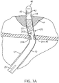
- a second set of nerve stimulation electrodes 244 and 246 (which may be bipolar electrodes) can be positioned proximally to electrodes 44 and 46 so that the pudenal nerve can be stimulated to relax the urinary sphincter US when the catheter body 12 is fully advanced in the urinary tract such that the catheter distal end 16 is positioned within the patients bladder B.
- the invention also provides systems for facilitating introduction of a urinary drainage catheter into the urinary tract of a patient.
- a system 52 comprising a urinary drainage catheter 10 having any or all of the characteristics described above in combination with a controller 50 configured to deliver high frequency current to the nerve stimulation electrode(s) on the urinary drainage catheter.
- the controller 50 may include its own electrical power source 54 (which may be an AC power supply) or can be configured to be coupled to an external electrical power source (not shown) such as various AC power supplies.
- the controller 50 will typically be configured to deliver stimulation current at a frequency above 4 kHz, an amperage below 15 mA, and a voltage in the range from 40V to 60V.
- the controller will typically be configured to deliver bipolar current to one or more electrode pairs on the catheter, but in other instances could be configured to deliver monopolar current to a single electrode on the drainage catheter and to also connect to a dispersive patch/return electrode on the patient of the type known for use with monopolar high frequency current delivery.
- the controller can also be configured to limit the total amount of delivered electrical energy/power to stay below that which would cause pain to the patient and/or injure, burn or otherwise damage tissue near the catheter tip including the pudendal nerve.
- Prevention of thermal or other injury to the urethra and pudendal nerve can be accomplished through a variety of means including control of the characteristics of the electrical energy delivered including current, frequency and voltage.
- control can be effectuated through the use of one or more thermal sensors 49 positioned in or on catheter body 12 in the area of electrodes 44 and 46 tip or other location on the catheter body to provide temperature information to control one more of the aforementioned characteristics so as to keep the temperature of tissue near the electrodes below a threshold level, for example, 45 °C, more preferably below 42.5°C and still more preferably below 40 °C.
- Sensors 49 may correspond to one or more thermal sensors known in the art including thermistors and thermocouples and they may be operatively coupled (e.g.
- Inputs 49i encoding information from such thermal sensors 49 can be used in various control algorithms such as P, PI or PID based and other like algorithms to maintain the tissue temperature below the threshold point. Such algorithms can be implemented in both hardware or software for example, via electronic instructions or module embedded in controller 50 or other logic resources used by catheter 10. Such inputs 49i can also be used to generate a thermal map of the urethral tissue and other tissue adjacent the electrode so that the physician can have a more comprehensive view of the thermal effect on the tissue during a current/energy delivery period.
- Prevention of thermal or electrical injury to the urethra and pudendal nerve can in various embodiments, also be achieved by control of the shape and area of the electrode or other energy delivery element.
- the area of the electrodes can range from about 0.1 mm to 100 mm 2 , with specific embodiments of 0.5, 1, 2.5, 5, 10, 20, 25, 50, 75 and 80 mm 2 . Larger areas can be used to reduce current density at a given electrode and in turn the degree of ohmic heating of tissue.
- shapes for the electrodes which can be employed to reduce pain or injury from ohmic heating include those having rounded edges such as circular, oval or rectangular with rounded edges (e.g., due to edge effects from higher current densities).
- Electrodes 44, 46 having selected sizes and shapes can be configured to be removably fitted (e.g. by a snap or press fit or other means known in the catheter arts) on to the catheter distal end 16. Once fitted, the physician can then advance the catheter into the urethra and do several test deliveries of electrical energy to determine if the electrode causes any pain pr discomfort to the patient.
- the electrode size and shape can be selected based on patient parameters such as size, weight, age, medical condition etc., relative to a population of those patients having those characteristics, in particular relative to the patient population in which the electrode characteristics (e.g., area, shape and material) do not cause pain or injury to the patient from ohmic heating.
- patient parameters such as size, weight, age, medical condition etc., relative to a population of those patients having those characteristics, in particular relative to the patient population in which the electrode characteristics (e.g., area, shape and material) do not cause pain or injury to the patient from ohmic heating.
- FIG. 4A and 4B An alternative embodiment of a distal end 116 of the catheter 110 is illustrated in Figs. 4A and 4B .
- the distal end 116 includes a distal tip 140, drain port 142, and inflatable balloon 122, all of which are similar or identical to those described in connection with Figs. 3A and 3B .
- the embodiment of Figs. 4A and 4B includes ring electrodes 144 and 146 which are axially spaced-apart near the distal tip 140, usually being located on either side of the drain port 142.
- the electrodes 144 and 146 may be connected to the wires or conductors 26 as described previously for electrodes 44 and 46.
- the electrodes may comprise tripolar electrode for use with a tripolar power supply.
- the urinary drainage catheter 10 may be introduced to a bladder B by first passing the distal end 16 of the catheter upward through the patient's urethra U. Advancement of the catheter 10 will be generally the same as for any Foley or other urinary drainage catheter until the distal end 16 of the catheter reaches the urinary sphincter US. Once the distal end 16 reaches the urinary sphincter, which may be detected by manually detecting an increased resistance to advancement, the user may energize controller 50 to deliver a stimulating current through the catheter electrodes 44 and 46.
- the urinary sphincter is anatomically close to the patient's pudenal nerves, and delivery of current through the urethral wall will stimulate the pudenal nerves. The particular frequencies, current levels, and voltages described above are known to induce relaxation of the urinary sphincter.
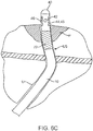
- distal tip 40 of the catheter 10 first reaches the urinary sphincter US with the sphincter generally constricted or closed, as shown in Fig. 6A .
- the stimulating current may then be delivered through electrodes 44 and 46, as generally shown in Fig. 6B , in order to open or otherwise relax the urinary sphincter US.
- the distal tip 40 of the catheter 10 may be advanced through the relaxed urinary sphincter so that it easily passes beyond the sphincter into the prostate P (in male patients) and eventually into the bladder where it functions as a normal urinary drainage catheter, as shown in Fig. 6C .
- relaxation or opening of the urinary sphincter US may be sensed by pressure/force sensor or other sensor 45 which may be placed at or near the distal tip 40 of catheter 10 and/or nearby (e.g. within several mm's) of electrodes 44 and 46
- sensors may correspond to various solid state pressure sensors such as a various solid state strain gauges known in the art including mems-based sensors.
- sensor 45 is configured to send an input to controller 50 including information on a sensed pressure or force by the sensor. Sensor 45 may also be used to sense when the distal tip of the catheter 40 has been positioned in the patient's bladder B by sensing a decrease or other change in pressure.
- controller 50 can also be configured to limit the total amount of delivered electrical energy/power to stay below that which would injure, burn or otherwise damage tissue near the catheter tip including the pudenal nerve.
- the controller 50 may be configured to receive an input from a temperature or other sensor 49 positioned on or near catheter tip 40 and utilize that input to control or otherwise regulate the delivery of electrical energy to the electrodes so as to stay below a selected temperature threshold which would injure or otherwise damage urethral or other tissue near the catheter tip.
- the controller may include a temperature control algorithm known in the art such as P, PI or PID or other like control algorithm. Such an algorithm can be implemented via an electronic instructions set embedded in a processor or other logic resources incorporated into or otherwise in communication with controller 50.
- the characteristics of the high frequency current or other energy used to relax the urinary sphincter can be tuned or otherwise adjusted to improve or optimize relaxation of the urinary sphincter.
- tuning or adjusted by measurement of urinary sphincter pressure using a pressure sensor 45 or other sensor coupled to catheter or another device.
- the high frequency current may be "tuned” (grossly adjusted) or “finely tuned” (finely adjusted) while observing or tracking changes in urinary sphincter pressures so as to identify those settings which result in a selected and/or maximum decrease in urinary sphincter pressure.
- Gross adjustments may incorporate changes in the range of about 5 to about 25%, while fine adjustments may those less than about 5%.
- the method comprises advancing the end 16 of the drainage catheter 10 through the urethra until the distal tip 40 reaches the patient's urinary sphincter US.
- tip location within the urethra can be determined by a pressure/force or other sensor 45 positioned on the tip 40 of the catheter 10, or through the use of radio-opaque, echogenic or other marker 47 placed on the distal end 16 or distal end area for imaging purposes or both.
- High frequency current is then delivered to the patient's pudenal nerve to relax the urinary sphincter, and the distal tip of the drainage catheter may then be advanced through the urinary sphincter US while the sphincter remains relaxed.
- Relaxation of the sphincter can be determined by imaging or through the use of a sensor 45 placed on the catheter end 16 or tip 40 as described above.
- the distal tip 40 of the drainage catheter 10 can be properly positioned in the patient's bladder in a manner similar to that for positioning ordinary urinary drainage catheters. Then the deployable anchor of the catheter typically, an inflatable balloon is inflated to anchor the distal portion of the catheter in place in the bladder. Once so anchored, in a similar function to a Foley catheter, catheter 10 can then drain urine from the bladder through the drainage lumen 18.
- energy can be delivered by the electrodes when the catheter is withdrawn so as to reduce pain and the risk of ureteral trauma or injury to the patient, and the procedure may be repeated whenever it is necessary to exchange drainage catheters in an individual patient.
- energy is applied to the pudendal nerve such that urinary sphincter is sufficiently relaxed to keep the force applied to the catheter and/or to the urethra (including the section of urethra in the area of the urinary sphincter) during advancement below a set threshold.
- the threshold may be below 2 lbs of force, more preferably below 1 lb of force, still more preferably below 0.51bs of force and still more preferably below 0.251bs of force.
- the force can be determined by a pressure/force sensor placed on near the drainage catheter tip and/or through other force sensor means.
- Relaxation of the sphincter can also be assessed in terms of the folds of the urinary sphincter and/or the folds in the section on the urethra in the area of the urinary sphincter being effaced.
- the folds are substantially effaced (substantially in this case being about 90% in terms of a ridge or valley in the urinary sphincter or urethra), though lesser amounts of effacement are also contemplated.
- Such effacement can be assessed be via one or more imaging modalities such as video, ultrasound, fluoroscopy and the like as wells as by pressure measurement.
- high frequency current or other energy can be periodically delivered to the pudendal nerve by catheter 10 so as to flush the patient's urethra.
- the electrode of group of electrode for doing can be the same or different from the electrode or group of electrodes used stimulate the pudendal nerve when catheter is being advanced near the patient's urinary spincter.
- high frequency current can be delivered by an embodiment of the drainage catheter 10 having electrodes 244 and 246 with the distal tip 40 of the catheter positioned in the patient's bladder so as to relax the urinary sphincter US (as described above, electrodes 244 and 246 are positioned proximally on catheter 10 so that are in the areas of the urinary sphincter US when the catheter tip 40 is positioned in the bladder).
- saline or other irrigation fluid 250 can be delivered through an irrigation lumen 25 out of an irrigation port or aperture 242 on catheter 10 so as to flow through and out the urethra to flush the urethra and catheter 10 of any bacteria or other infectious microorganisms (e.g., fungus etc.).
- a urinary tract infection including infection of the urinary drainage catheter that often occurs when a Foley or other urinary drainage catheter is left in place in the patient's urinary tract for an extended period of time. It also allows the same urinary drainage catheter to remain in place for longer time period to time without the need for periodic replacement saving time and expense and reducing patient discomfort from repeated removal and insertion of a new catheter each time.
Landscapes
- Health & Medical Sciences (AREA)
- Life Sciences & Earth Sciences (AREA)
- General Health & Medical Sciences (AREA)
- Engineering & Computer Science (AREA)
- Biomedical Technology (AREA)
- Veterinary Medicine (AREA)
- Public Health (AREA)
- Animal Behavior & Ethology (AREA)
- Heart & Thoracic Surgery (AREA)
- Radiology & Medical Imaging (AREA)
- Nuclear Medicine, Radiotherapy & Molecular Imaging (AREA)
- Biophysics (AREA)
- Anesthesiology (AREA)
- Hematology (AREA)
- Pulmonology (AREA)
- Urology & Nephrology (AREA)
- Gastroenterology & Hepatology (AREA)
- Cardiology (AREA)
- Child & Adolescent Psychology (AREA)
- Epidemiology (AREA)
- Physiology (AREA)
- Neurology (AREA)
- Neurosurgery (AREA)
- Electrotherapy Devices (AREA)
- External Artificial Organs (AREA)
- Media Introduction/Drainage Providing Device (AREA)
- Measuring And Recording Apparatus For Diagnosis (AREA)
- Surgical Instruments (AREA)
Applications Claiming Priority (3)
| Application Number | Priority Date | Filing Date | Title |
|---|---|---|---|
| US201662302668P | 2016-03-02 | 2016-03-02 | |
| EP17760859.3A EP3423142B1 (en) | 2016-03-02 | 2017-03-02 | Urethral catheters for facilitated introduction into the urinary tract |
| PCT/US2017/020543 WO2017151986A1 (en) | 2016-03-02 | 2017-03-02 | Urethral catheters and methods for facilitated introduction into the urinary tract |
Related Parent Applications (1)
| Application Number | Title | Priority Date | Filing Date |
|---|---|---|---|
| EP17760859.3A Division EP3423142B1 (en) | 2016-03-02 | 2017-03-02 | Urethral catheters for facilitated introduction into the urinary tract |
Publications (1)
| Publication Number | Publication Date |
|---|---|
| EP3878503A1 true EP3878503A1 (en) | 2021-09-15 |
Family
ID=59723342
Family Applications (2)
| Application Number | Title | Priority Date | Filing Date |
|---|---|---|---|
| EP21171353.2A Withdrawn EP3878503A1 (en) | 2016-03-02 | 2017-03-02 | Urethral catheters for facilitated introduction into the urinary tract |
| EP17760859.3A Active EP3423142B1 (en) | 2016-03-02 | 2017-03-02 | Urethral catheters for facilitated introduction into the urinary tract |
Family Applications After (1)
| Application Number | Title | Priority Date | Filing Date |
|---|---|---|---|
| EP17760859.3A Active EP3423142B1 (en) | 2016-03-02 | 2017-03-02 | Urethral catheters for facilitated introduction into the urinary tract |
Country Status (9)
| Country | Link |
|---|---|
| US (3) | US10589093B2 (https=) |
| EP (2) | EP3878503A1 (https=) |
| JP (3) | JP6861721B2 (https=) |
| CN (2) | CN109069798A (https=) |
| AU (1) | AU2017225989B2 (https=) |
| CA (1) | CA3016033A1 (https=) |
| DK (1) | DK3423142T3 (https=) |
| ES (1) | ES2884177T3 (https=) |
| WO (1) | WO2017151986A1 (https=) |
Families Citing this family (25)
| Publication number | Priority date | Publication date | Assignee | Title |
|---|---|---|---|---|
| MX348673B (es) | 2008-05-01 | 2017-06-23 | Convatec Tech Inc * | Dispositivo de drenaje rectal. |
| CN103533969A (zh) | 2011-03-17 | 2014-01-22 | 康沃特克科技公司 | 高阻隔性弹性体粪便导管或造口袋 |
| CA2856732A1 (en) | 2011-12-09 | 2013-06-13 | Metavention, Inc. | Therapeutic neuromodulation of the hepatic system |
| US20150111918A1 (en) | 2012-03-08 | 2015-04-23 | Medtronic Ardian Luxembourg S.a.r.l | Immune system neuromodulation and associated systems and methods |
| CA2913346A1 (en) | 2013-06-05 | 2014-12-11 | Metavention, Inc. | Modulation of targeted nerve fibers |
| CA2918607C (en) | 2013-08-01 | 2024-02-20 | Convatec Technologies Inc. | Self-closing bag connector |
| EP3226795B1 (en) | 2014-12-03 | 2020-08-26 | Metavention, Inc. | Systems for modulating nerves or other tissue |
| CN109069798A (zh) | 2016-03-02 | 2018-12-21 | 因库博实验室有限责任公司 | 尿道导管和便于引入泌尿道的方法 |
| US10524859B2 (en) | 2016-06-07 | 2020-01-07 | Metavention, Inc. | Therapeutic tissue modulation devices and methods |
| GB201721955D0 (en) | 2017-12-27 | 2018-02-07 | Convatec Ltd | Catheter wetting devices |
| GB201721956D0 (en) | 2017-12-27 | 2018-02-07 | Convatec Ltd | Female catheter locator tip |
| US11864825B2 (en) * | 2018-05-02 | 2024-01-09 | Biosense Webster (Israel) Ltd. | Ablation catheter with selective radial energy delivery |
| FR3080774B1 (fr) * | 2018-05-04 | 2022-07-15 | Univ Bordeaux | Catheter, ballon gonflable pour cathether |
| JP7476188B2 (ja) * | 2018-11-01 | 2024-04-30 | インキューブ ラブズ, エルエルシー | 神経因性膀胱の治療のためのデバイス、システム、および方法 |
| AU2020290905A1 (en) | 2019-06-11 | 2021-11-18 | Convatec Technologies Inc. | Urine collection bags for use with catheter products, kits incorporating the same, and methods therefor |
| CN211884905U (zh) | 2019-08-22 | 2020-11-10 | 贝克顿·迪金森公司 | 球囊扩张导管及其球囊 |
| CN211856471U (zh) | 2019-08-22 | 2020-11-03 | 贝克顿·迪金森公司 | 回声医疗器械回声反射性量化测试系统 |
| CN112401971B (zh) | 2019-08-23 | 2025-09-09 | 贝克顿·迪金森公司 | 为经皮肾镜取石术外科手术设计的套件 |
| CA3143595A1 (en) * | 2019-11-20 | 2021-05-27 | Ian S MIDDLETON | An actively deflectable urinary catheter |
| US11896844B2 (en) * | 2019-12-13 | 2024-02-13 | NU-RISE Lda | Urinary catheter for detecting radiation |
| US12594399B2 (en) | 2021-04-12 | 2026-04-07 | Convatec Limited | Catheter |
| CN113289217B (zh) * | 2021-07-06 | 2025-04-04 | 江苏伊凯医疗器械有限公司 | 一次性双腔输尿管导管 |
| CN113499533B (zh) * | 2021-07-26 | 2023-04-28 | 重庆大学附属肿瘤医院 | 一种尿道灌注器 |
| CN114010316A (zh) * | 2021-11-24 | 2022-02-08 | 北京华科恒生医疗科技有限公司 | 一种适配神经导航的引流管 |
| CN115645696A (zh) * | 2022-12-13 | 2023-01-31 | 山东百多安医疗器械股份有限公司 | 一种双套囊神经监护气管插管 |
Citations (11)
| Publication number | Priority date | Publication date | Assignee | Title |
|---|---|---|---|---|
| US5529574A (en) * | 1992-08-21 | 1996-06-25 | Frackelton; James P. | Method and apparatus for treatment of the prostate |
| JP2002301087A (ja) * | 2001-04-06 | 2002-10-15 | Shutaro Satake | 多目的アブレーション用バルーンカテーテル |
| US20120226098A1 (en) * | 2008-12-09 | 2012-09-06 | Nephera Ltd. | Stimulation of the urinary system |
| US20130261692A1 (en) * | 2012-03-27 | 2013-10-03 | Urologix Inc. | Neuromodulation system and related methods |
| US20140058588A1 (en) | 2012-08-24 | 2014-02-27 | GM Global Technology Operations LLC | Device for configuring a motor vehicle |
| US20140058284A1 (en) | 2012-08-22 | 2014-02-27 | Innovative Surgical Solutions, Llc | Nerve monitoring system |
| US20140128766A1 (en) | 2012-11-05 | 2014-05-08 | Anthony V. Beran | Foley catheter |
| US20140249595A1 (en) | 2007-08-02 | 2014-09-04 | University Of Pittsburgh - Of The Commonwealth System Of Higher Education | Methods and Systems for Achieving a Physiological Response by Pudendal Nerve Stimulation and Blockade |
| US20140309550A1 (en) | 2011-11-28 | 2014-10-16 | Remendium Labs Llc | Treatment of urinary incontinence |
| US20150126839A1 (en) * | 2013-11-01 | 2015-05-07 | Medtronic Xomed, Inc. | Foley catheter with ring electrodes |
| US20150328454A1 (en) * | 2014-05-14 | 2015-11-19 | Bio Health Frontiers, Incorporated | Electrical neuromodulation stimulation system and method for treating urinary incontinence |
Family Cites Families (21)
| Publication number | Priority date | Publication date | Assignee | Title |
|---|---|---|---|---|
| DE3534124A1 (de) | 1985-09-25 | 1987-04-02 | Celltek Gmbh & Co Kg | Sphinktertrainer |
| US6338726B1 (en) | 1997-02-06 | 2002-01-15 | Vidacare, Inc. | Treating urinary and other body strictures |
| US6941171B2 (en) * | 1998-07-06 | 2005-09-06 | Advanced Bionics Corporation | Implantable stimulator methods for treatment of incontinence and pain |
| EP1416903A2 (en) * | 2001-07-20 | 2004-05-12 | Alfred E. Mann Institute for Biomedical Engineering at the University of Southern California | Method and apparatus for the treatment of urinary tract dysfunction |
| US6994706B2 (en) * | 2001-08-13 | 2006-02-07 | Minnesota Medical Physics, Llc | Apparatus and method for treatment of benign prostatic hyperplasia |
| AU2004212599A1 (en) * | 2003-09-19 | 2005-04-07 | Neopraxis Pty Ltd | Sphincteric control system |
| US7894913B2 (en) * | 2004-06-10 | 2011-02-22 | Medtronic Urinary Solutions, Inc. | Systems and methods of neuromodulation stimulation for the restoration of sexual function |
| EP1853344A4 (en) * | 2005-03-02 | 2008-05-28 | Continence Control Systems Int | IMPROVED METHOD AND DEVICE FOR TREATING INCONTINENCE |
| US8109982B2 (en) * | 2005-06-23 | 2012-02-07 | Morteza Naghavi | Non-invasive modulation of the autonomic nervous system |
| JP2008018235A (ja) * | 2006-06-22 | 2008-01-31 | Thermarx Inc | 自律神経系の非侵襲的調節 |
| US8032222B2 (en) * | 2007-06-19 | 2011-10-04 | Loushin Michael K H | Device for electrically and mechanically stimulating a compartment in a body |
| EP2160133B1 (en) * | 2007-06-27 | 2020-08-19 | Flip Technologies Limited | A system for use in a procedure for improving a sealing function of a sphincter |
| KR100983879B1 (ko) * | 2009-05-12 | 2010-09-30 | (주)프레스티지 메디케어 | 전립선 치료용 카테터 |
| US20140288612A1 (en) * | 2012-04-26 | 2014-09-25 | Pneumoflex Systems, Llc | System to treat at least one of the urethral and anal sphincters |
| US20140058288A1 (en) * | 2012-08-22 | 2014-02-27 | Innovative Surgical Solutions, Llc | Sphincter contraction sensor |
| EP2928399A4 (en) * | 2012-12-09 | 2016-08-24 | Autonomix Medical Inc | REGULATION OF ORGAN AND TUMOR GROWTH RATES, FUNCTION AND DEVELOPMENT |
| CN203264007U (zh) * | 2013-05-15 | 2013-11-06 | 蒋民军 | 一种可尿道冲洗导尿管 |
| CN104162228B (zh) * | 2014-08-19 | 2016-06-29 | 武汉海德润医疗设备有限公司 | 锯齿波脉冲信号仪及前列腺治疗仪器 |
| DK3405250T3 (da) | 2016-01-19 | 2021-02-15 | Incube Labs Llc | Systemer til patient-aktiveret blærekontrol |
| US20170231547A1 (en) | 2016-02-12 | 2017-08-17 | Incube Labs, Llc | Apparatus and methods for screening patients for bladder control via pudendal nerve stimulation |
| CN109069798A (zh) | 2016-03-02 | 2018-12-21 | 因库博实验室有限责任公司 | 尿道导管和便于引入泌尿道的方法 |
-
2017
- 2017-03-02 CN CN201780026709.0A patent/CN109069798A/zh active Pending
- 2017-03-02 ES ES17760859T patent/ES2884177T3/es active Active
- 2017-03-02 WO PCT/US2017/020543 patent/WO2017151986A1/en not_active Ceased
- 2017-03-02 JP JP2018545589A patent/JP6861721B2/ja not_active Expired - Fee Related
- 2017-03-02 CN CN202110260921.1A patent/CN113144419A/zh active Pending
- 2017-03-02 AU AU2017225989A patent/AU2017225989B2/en not_active Ceased
- 2017-03-02 EP EP21171353.2A patent/EP3878503A1/en not_active Withdrawn
- 2017-03-02 DK DK17760859.3T patent/DK3423142T3/da active
- 2017-03-02 EP EP17760859.3A patent/EP3423142B1/en active Active
- 2017-03-02 CA CA3016033A patent/CA3016033A1/en active Pending
- 2017-03-02 US US15/448,501 patent/US10589093B2/en active Active
-
2020
- 2020-01-15 US US16/743,361 patent/US11439819B2/en active Active
-
2021
- 2021-03-30 JP JP2021056958A patent/JP7133058B2/ja active Active
-
2022
- 2022-07-29 US US17/877,358 patent/US20220362552A1/en not_active Abandoned
- 2022-08-26 JP JP2022134844A patent/JP2022162133A/ja active Pending
Patent Citations (11)
| Publication number | Priority date | Publication date | Assignee | Title |
|---|---|---|---|---|
| US5529574A (en) * | 1992-08-21 | 1996-06-25 | Frackelton; James P. | Method and apparatus for treatment of the prostate |
| JP2002301087A (ja) * | 2001-04-06 | 2002-10-15 | Shutaro Satake | 多目的アブレーション用バルーンカテーテル |
| US20140249595A1 (en) | 2007-08-02 | 2014-09-04 | University Of Pittsburgh - Of The Commonwealth System Of Higher Education | Methods and Systems for Achieving a Physiological Response by Pudendal Nerve Stimulation and Blockade |
| US20120226098A1 (en) * | 2008-12-09 | 2012-09-06 | Nephera Ltd. | Stimulation of the urinary system |
| US20140309550A1 (en) | 2011-11-28 | 2014-10-16 | Remendium Labs Llc | Treatment of urinary incontinence |
| US20130261692A1 (en) * | 2012-03-27 | 2013-10-03 | Urologix Inc. | Neuromodulation system and related methods |
| US20140058284A1 (en) | 2012-08-22 | 2014-02-27 | Innovative Surgical Solutions, Llc | Nerve monitoring system |
| US20140058588A1 (en) | 2012-08-24 | 2014-02-27 | GM Global Technology Operations LLC | Device for configuring a motor vehicle |
| US20140128766A1 (en) | 2012-11-05 | 2014-05-08 | Anthony V. Beran | Foley catheter |
| US20150126839A1 (en) * | 2013-11-01 | 2015-05-07 | Medtronic Xomed, Inc. | Foley catheter with ring electrodes |
| US20150328454A1 (en) * | 2014-05-14 | 2015-11-19 | Bio Health Frontiers, Incorporated | Electrical neuromodulation stimulation system and method for treating urinary incontinence |
Also Published As
| Publication number | Publication date |
|---|---|
| CA3016033A1 (en) | 2017-09-08 |
| US11439819B2 (en) | 2022-09-13 |
| US10589093B2 (en) | 2020-03-17 |
| EP3423142B1 (en) | 2021-05-19 |
| ES2884177T3 (es) | 2021-12-10 |
| WO2017151986A1 (en) | 2017-09-08 |
| JP6861721B2 (ja) | 2021-04-21 |
| JP2022162133A (ja) | 2022-10-21 |
| CN113144419A (zh) | 2021-07-23 |
| AU2017225989B2 (en) | 2021-12-02 |
| JP2021106891A (ja) | 2021-07-29 |
| EP3423142A4 (en) | 2019-11-06 |
| DK3423142T3 (da) | 2021-08-23 |
| JP7133058B2 (ja) | 2022-09-07 |
| US20170252560A1 (en) | 2017-09-07 |
| US20200188662A1 (en) | 2020-06-18 |
| US20220362552A1 (en) | 2022-11-17 |
| EP3423142A1 (en) | 2019-01-09 |
| CN109069798A (zh) | 2018-12-21 |
| AU2017225989A1 (en) | 2018-10-25 |
| JP2019512291A (ja) | 2019-05-16 |
Similar Documents
| Publication | Publication Date | Title |
|---|---|---|
| US20220362552A1 (en) | Urethral catheters and methods for facilitated introduction into the urinary tract | |
| US12133980B2 (en) | Device, systems and methods for treatment of neurogenic bladder | |
| US5529574A (en) | Method and apparatus for treatment of the prostate | |
| CN105056397B (zh) | 植入式神经电刺激电极组件及其应用方法 | |
| US20130261692A1 (en) | Neuromodulation system and related methods | |
| US20140324144A1 (en) | Minimally invasive methods for implanting a sacral stimulation lead | |
| CN108883278B (zh) | 针对通过阴部神经刺激的膀胱控制筛选患者的设备和方法 | |
| US20060206183A1 (en) | Spinal cord stimulator lead for neurostimulation having a fluid delivery lumen and/0r a distensible balloon | |
| US20060052765A1 (en) | Percutaneous lead for neurostimulation having a fluid delivery lumen | |
| CN117618769A (zh) | 一种刺激电极装置 | |
| EP3585291B1 (en) | System for improving location accuracy of a radiofrequency ablation procedure via fiducial marking | |
| JP2019055026A (ja) | 電極付挿入体 |
Legal Events
| Date | Code | Title | Description |
|---|---|---|---|
| PUAI | Public reference made under article 153(3) epc to a published international application that has entered the european phase |
Free format text: ORIGINAL CODE: 0009012 |
|
| STAA | Information on the status of an ep patent application or granted ep patent |
Free format text: STATUS: THE APPLICATION HAS BEEN PUBLISHED |
|
| AC | Divisional application: reference to earlier application |
Ref document number: 3423142 Country of ref document: EP Kind code of ref document: P |
|
| AK | Designated contracting states |
Kind code of ref document: A1 Designated state(s): AL AT BE BG CH CY CZ DE DK EE ES FI FR GB GR HR HU IE IS IT LI LT LU LV MC MK MT NL NO PL PT RO RS SE SI SK SM TR |
|
| STAA | Information on the status of an ep patent application or granted ep patent |
Free format text: STATUS: REQUEST FOR EXAMINATION WAS MADE |
|
| 17P | Request for examination filed |
Effective date: 20220315 |
|
| RBV | Designated contracting states (corrected) |
Designated state(s): AL AT BE BG CH CY CZ DE DK EE ES FI FR GB GR HR HU IE IS IT LI LT LU LV MC MK MT NL NO PL PT RO RS SE SI SK SM TR |
|
| P01 | Opt-out of the competence of the unified patent court (upc) registered |
Effective date: 20230526 |
|
| STAA | Information on the status of an ep patent application or granted ep patent |
Free format text: STATUS: THE APPLICATION IS DEEMED TO BE WITHDRAWN |
|
| 18D | Application deemed to be withdrawn |
Effective date: 20231003 |