EP3878025B1 - Motor vehicle battery support device - Google Patents
Motor vehicle battery support device Download PDFInfo
- Publication number
- EP3878025B1 EP3878025B1 EP19786604.9A EP19786604A EP3878025B1 EP 3878025 B1 EP3878025 B1 EP 3878025B1 EP 19786604 A EP19786604 A EP 19786604A EP 3878025 B1 EP3878025 B1 EP 3878025B1
- Authority
- EP
- European Patent Office
- Prior art keywords
- wall
- support
- air filter
- battery
- supporting part
- Prior art date
- Legal status (The legal status is an assumption and is not a legal conclusion. Google has not performed a legal analysis and makes no representation as to the accuracy of the status listed.)
- Active
Links
- 230000002093 peripheral effect Effects 0.000 claims description 11
- 230000002787 reinforcement Effects 0.000 claims description 5
- 230000001681 protective effect Effects 0.000 description 6
- 238000007872 degassing Methods 0.000 description 5
- 239000007787 solid Substances 0.000 description 5
- 230000010354 integration Effects 0.000 description 4
- 239000002253 acid Substances 0.000 description 3
- 208000031968 Cadaver Diseases 0.000 description 2
- 241000897276 Termes Species 0.000 description 2
- 239000006096 absorbing agent Substances 0.000 description 1
- 238000003172 battery degassing Methods 0.000 description 1
- 238000005452 bending Methods 0.000 description 1
- 238000002485 combustion reaction Methods 0.000 description 1
- 230000000295 complement effect Effects 0.000 description 1
- 239000000470 constituent Substances 0.000 description 1
- 230000007797 corrosion Effects 0.000 description 1
- 238000005260 corrosion Methods 0.000 description 1
- 238000006073 displacement reaction Methods 0.000 description 1
- 238000009434 installation Methods 0.000 description 1
- 238000012423 maintenance Methods 0.000 description 1
- 238000004519 manufacturing process Methods 0.000 description 1
- 239000000463 material Substances 0.000 description 1
- 238000000034 method Methods 0.000 description 1
- 238000012986 modification Methods 0.000 description 1
- 230000004048 modification Effects 0.000 description 1
- 230000010355 oscillation Effects 0.000 description 1
- 238000000926 separation method Methods 0.000 description 1
- 230000035939 shock Effects 0.000 description 1
Images


Classifications
-
- B—PERFORMING OPERATIONS; TRANSPORTING
- B60—VEHICLES IN GENERAL
- B60R—VEHICLES, VEHICLE FITTINGS, OR VEHICLE PARTS, NOT OTHERWISE PROVIDED FOR
- B60R16/00—Electric or fluid circuits specially adapted for vehicles and not otherwise provided for; Arrangement of elements of electric or fluid circuits specially adapted for vehicles and not otherwise provided for
- B60R16/02—Electric or fluid circuits specially adapted for vehicles and not otherwise provided for; Arrangement of elements of electric or fluid circuits specially adapted for vehicles and not otherwise provided for electric constitutive elements
- B60R16/04—Arrangement of batteries
-
- B—PERFORMING OPERATIONS; TRANSPORTING
- B60—VEHICLES IN GENERAL
- B60L—PROPULSION OF ELECTRICALLY-PROPELLED VEHICLES; SUPPLYING ELECTRIC POWER FOR AUXILIARY EQUIPMENT OF ELECTRICALLY-PROPELLED VEHICLES; ELECTRODYNAMIC BRAKE SYSTEMS FOR VEHICLES IN GENERAL; MAGNETIC SUSPENSION OR LEVITATION FOR VEHICLES; MONITORING OPERATING VARIABLES OF ELECTRICALLY-PROPELLED VEHICLES; ELECTRIC SAFETY DEVICES FOR ELECTRICALLY-PROPELLED VEHICLES
- B60L50/00—Electric propulsion with power supplied within the vehicle
- B60L50/50—Electric propulsion with power supplied within the vehicle using propulsion power supplied by batteries or fuel cells
- B60L50/60—Electric propulsion with power supplied within the vehicle using propulsion power supplied by batteries or fuel cells using power supplied by batteries
- B60L50/64—Constructional details of batteries specially adapted for electric vehicles
-
- H—ELECTRICITY
- H01—ELECTRIC ELEMENTS
- H01M—PROCESSES OR MEANS, e.g. BATTERIES, FOR THE DIRECT CONVERSION OF CHEMICAL ENERGY INTO ELECTRICAL ENERGY
- H01M50/00—Constructional details or processes of manufacture of the non-active parts of electrochemical cells other than fuel cells, e.g. hybrid cells
- H01M50/20—Mountings; Secondary casings or frames; Racks, modules or packs; Suspension devices; Shock absorbers; Transport or carrying devices; Holders
- H01M50/249—Mountings; Secondary casings or frames; Racks, modules or packs; Suspension devices; Shock absorbers; Transport or carrying devices; Holders specially adapted for aircraft or vehicles, e.g. cars or trains
-
- Y—GENERAL TAGGING OF NEW TECHNOLOGICAL DEVELOPMENTS; GENERAL TAGGING OF CROSS-SECTIONAL TECHNOLOGIES SPANNING OVER SEVERAL SECTIONS OF THE IPC; TECHNICAL SUBJECTS COVERED BY FORMER USPC CROSS-REFERENCE ART COLLECTIONS [XRACs] AND DIGESTS
- Y02—TECHNOLOGIES OR APPLICATIONS FOR MITIGATION OR ADAPTATION AGAINST CLIMATE CHANGE
- Y02E—REDUCTION OF GREENHOUSE GAS [GHG] EMISSIONS, RELATED TO ENERGY GENERATION, TRANSMISSION OR DISTRIBUTION
- Y02E60/00—Enabling technologies; Technologies with a potential or indirect contribution to GHG emissions mitigation
- Y02E60/10—Energy storage using batteries
Definitions
- the invention relates to a battery support device for a motor vehicle, in particular a motor vehicle comprising an internal combustion, electric or hybrid engine.
- the invention also relates to a motor vehicle comprising such a device.
- Motor vehicles are generally equipped with one or more batteries of all sizes to meet the electrical needs of the vehicles.
- a battery is arranged in the engine compartment of the vehicle, in particular, in the bottom of said compartment. Said battery is used to start the engine when it is started and to be powered by the latter during its operation to distribute the energy to additional options, via power supply cables.
- fuse and relay boxes are connected to the battery to protect the entire electrical circuit.
- the power supply cables are arranged as close as possible to each other in such a way to form a compact block.
- an air filter can be part of this block, in particular by being fixed to a battery support device, often cantilevered, for the same reason of limited space in the engine compartment.
- the battery support device can be a simple support tray.
- FIG 9 illustrates an existing arrangement of an air filter 3 with a battery support pan 100.
- the air filter 3 is connected to the support tray 100 via a fixing means.
- the fixing means 150 is an elongated fixing bracket which is fixed on the one hand to a bottom of the support tray 100 and on the other hand to the air filter 3.
- the elongated shape of the fixing lug does not guarantee good support and correct positioning of the air filter.
- the weight of the air filter exerts a force on the mounting bracket.
- the force induced by the weight of the air filter can cause the mounting bracket to bend.
- An object of the present invention is to respond to the drawbacks of the prior art mentioned above and in particular, to propose a rigid and stable fixing of the air filter to the battery support tray while allowing a compact arrangement of these two elements.
- a first aspect of the invention relates to a battery support device for a motor vehicle, comprising a support tray intended to receive a battery.
- Said container comprises a bottom and at least one wall extending vertically from the bottom.
- the device comprises a chute extending, in a horizontal direction, from a peripheral edge of the bottom and comprising means for fixing with an air filter.
- the support device comprises a support piece housed in the chute and fixed on the one hand to said chute, and on the other hand to at least one wall of the tank.
- the proposed solution makes it possible to solve the aforementioned problems.
- the whole of the trunking and of the support part has a higher rigidity than that of a single fixing lug of the example cited above.
- the weight of said assembly therefore makes it possible to better compensate for the weight of the air filter.
- the force exerted by the air filter on the trunking is less than the force exerted by the air filter on the mounting lug.
- the attachment between the air filter and the support device is solid.
- fixing the support piece to at least one of the walls of the support tray and to the chute makes it possible to better carry the air filter. Indeed, the effort induced by the filter is taken up on the one hand by the support part and on the other hand by the chute integrating the support device and stiffened in the presence of the support part.
- the air filter is held fixed firmly to the support device without oscillations, despite the cantilevered position of said filter.
- the air filter fixed to the support device forms a compact block which can be easily installed in a confined space of the engine compartment.
- the invention also relates to an assembly for fixing and arranging a battery in a motor vehicle compartment.
- this assembly comprises a battery support device according to the invention, a battery, and an air filter.
- the invention also relates to a motor vehicle which comprises a battery support device according to the invention or an assembly according to the invention.
- a support device 1 receives a battery 2.
- the latter can in particular be fixed to the support device 1.
- An air filter 3 is fixed to one side of the support device, here, by screwing.
- the support device 1 comprises a bottom 11 on which the battery 2 rests, and several walls extending vertically from the bottom 11.
- the vertical walls form a perimeter 12 surrounding a part bottom of battery 122.
- the bottom 11 of the support tray is elongated along the longitudinal horizontal axis L.
- the bottom 11 extends in width along the horizontal transverse axis T and which is perpendicular to the axis L.
- the perimeter walls 12 extend from the bottom 11 along the vertical axis V which is perpendicular to the longitudinal horizontal axis L as well as to the transverse axis T so that these three axes L, V , T form a direct orthogonal frame as shown in the figures 1 to 8 .
- the terms "front”, “rear”, are defined with respect to the longitudinal axis L, the terms “lower”, “upper” are defined with respect to the axis V and the term “lateral” is defined with respect to the T axis.
- the bottom 11 and the periphery 12 form a support tray 10.
- the support device 1 further comprises a chute 15 extending horizontally from a first peripheral edge of the bottom 11.
- the first peripheral edge is a side edge 111 of the bottom 11.
- a fixing plate 151 is arranged at a first longitudinal end 15a of the chute 15.
- the fixing plate 151 comprises, here, a threaded hole 152 which will find face to face a threaded hole carried by the air filter 3 when this latter is attached to the support device 1.
- a screw 31, illustrated in the picture 2 crosses the two holes and a bolt cooperates with the screw 31 to ensure the maintenance of the air filter 3 to the support device 1.
- This force induced by the weight of the air filter 3 is absorbed by the assembly of the chute 15 and a support piece 16 so as to create a stable and solid attachment of the air filter 3 to the support device 1.
- the chute 15 and the support tray 10 are formed in one piece.
- the air filter support, here produced by the chute 15, is integrated into the support tray 10, which makes it possible to reduce the number of separate parts of the assembly and the uncertainty in the positioning of the air filter. 3 with respect to support device 1.
- the support device 100 of the prior art comprises the air filter support 150 separate from the support tray.
- the rib chain shown in the figure 9 includes at least one more rib than the chain of rib shown in the figure 1 .
- the additional rib is represented by the vector called A1 of the figure 9 .
- the support piece 16 is housed in the trough 15.
- the support piece 16 is fixed to the trough 15 at a fixing point arranged next to the threaded hole 152.
- the fixing point comprises an opening 153 made on the mounting plate.
- the opening 153 will be opposite an opening carried by the support part 16.
- a rivet passes through these openings and thus assembles the support part 16 and the chute15.
- other assembly means can be envisaged.
- support piece 16 comprises an elongated hollow body having an inverted U-shaped profile.
- the support piece 16, once mounted from the chute 15, is considered as a cover which closes the opening of the chute 15.
- the support piece 16, arranged in the chute 15, therefore has a first lateral side 161 which is oriented towards the air filter 3 and a second lateral side 162 which is oriented towards the support tray 10.
- the support piece 16 also comprises the means for fixing with the support tray 10, or more precisely with the periphery 12 of the support tray 10. In the example illustrated, these fixing means are all arranged on the second lateral side 162.
- the support piece 16 On the second lateral side 162, the support piece 16 comprises a primary wall 163 and a secondary wall 164 extending parallel to each other and laterally separated from each other by a space E. Described otherwise , the primary wall 163, the secondary wall 164 and an upper wall 165 define a groove 166 open at the bottom. The space E or the groove 166 receives a first wall 121 which extends vertically from the first peripheral edge 111 of the bottom 11.
- the primary and secondary walls 163 and 164 are located on either side of the first wall 121.
- the primary wall 163 is located at the outside of a space S delimited by the bottom 11 and the periphery 12 while the secondary wall 164 is inside this space S.
- the primary wall 163 is also called the outer wall 163 and the secondary wall 164 wall internal.
- the support piece 16 is arranged so that the space E between the primary and secondary walls 163, 164 has a width e1 equal to or slightly greater than the width e2 of the first wall 121.
- the first wall 121 and the groove 166 fit together well in order, on the one hand, to firmly hold the support piece 16 in place in the chute 15 and, on the other hand, to avoid lateral displacements of the support piece 16 with respect to the support device 1.
- the support piece 16 further comprises a lateral flange 167 extending perpendicularly to a longitudinal axis L1 of said piece.
- the side wing 167 comprising a first hole 168.
- the side wing is arranged so that when the support piece 16 is introduced into the chute, the first hole 168 is aligned axially with a second hole 123 made on a second wall 122 perpendicular to the first wall 121.
- a rivet or a screw passes through the holes 168 and 123 to fix the support part 16 to the second wall 122.
- the support piece 16 comprises a first fixing means with the periphery 12, precisely with the first wall 121, consisting of a space E or a groove 166 delimited by the primary and secondary walls 163, 164 and by the upper wall 165.
- the support piece 16 further comprises a second means of fixing with the periphery 12, precisely with the second wall 122, consisting of a through fixing hole 168.
- a reinforcement 13 extends between the hole 153 and the hole 168, that is to say between the point of attachment of the support part 16 with the chute 15 and the point of attachment of the support part with the second wall 122.
- the reinforcement 13 is a bar bringing additional material to the vicinity of the attachment points of the support piece 16 with the chute 15 and with the support tray 10 in order to make the attachment between the elements more solid. aforementioned.
- the support piece 16 is designed to perform other practical functions such as protecting a screw hole made in the bottom 11 of the support tray 10, the arrangement of the power supply cables and a degassing hose, and holder for a fuse and relay box. These functions will be detailed below in the description.
- the first wall 121 of the perimeter 12 has a convex portion 121a seen from the outside.
- Such a particular profile of the first wall 121 is due to the presence of a screw hole 17 at the foot of said first wall 121.
- the screw well 17 is intended to receive in particular screws for fixing the support tray 10 to a vehicle body structure.
- a vehicle shock occurs, it is possible that acid leaks can occur in the case of lead-acid batteries, which leads to a risk of corrosion of the fixing screws of the support tray and therefore a risk of separation of the support tray with the body structure.
- a protective plug 7 is mounted on the support part 16 so as to be face to face with the screw well 17 when said support part is mounted in the chute 15.
- the protective plug 7 is installed at a free end of the secondary wall 164 of the support piece 16. More specifically, the protective plug 7 extends parallel to the bottom 11 of the support tray 10 from a free end of a concave portion 164a of the secondary wall 164.
- the primary and secondary walls 163 and 164 of the support piece also include respective concave portions 163a and 164a to adapt to the concave portion 121a of the first wall 121.
- the protective cap 7 has a circular section whose diameter is equal to or slightly less than the diameter of the screw well 17 to be fitted into said well 17 and to cover almost all, or even all of the opening of the well.
- the height of the secondary wall 164 of the support piece 16 is dimensioned so that when the support piece 16 is mounted on the periphery 12, the upper face 70 of the protective cap 7 is flush with the upper face 110 of the bottom 11.
- the flatness of the bottom 11 is respected, which allows a stable installation of the battery 2 on the bottom 11.
- the support piece 16 can also carry electrical power cables used for example to power the motor dynamic loop. As observed on the figure 4 , the space provided by the hollow body of the support piece 16 is cleverly exploited as a passage for the power supply cables. Support clamps 8 for cables are installed in the space of the hollow body to hold the wiring. These collars can be of the self-tightening type.
- the power supply cables, fixed to the support piece 16, are therefore protected at the bottom by the chute 15, at the top by the support piece 16 and on the side by the side walls of the support piece 16 and the trunking 15.
- the cables can therefore have a thin covering, or even have no covering, which makes it possible to reduce the manufacturing costs of these cables.
- the support piece 16 allows wiring to be indexed in the engine compartment of the vehicle.
- the support piece 16 offers a housing for a battery degassing pipe.
- a slot 9 is made on the secondary wall 164.
- the slot 9, located at a rear end of the support piece 16, is arranged to receive the degassing pipe 29 of the battery 2 and to hold it.
- the support piece 16 comprises means for fixing and positioning a box 4 of fuses and relays.
- the fixing and positioning means consist of an island 41 and a plate 42, these two elements being arranged face to face and extending vertically from the upper face 165 of the part support 16.
- the distance d between the island 41 and the plate 42 here corresponds to the length L of the box 4 of fuse and relay.
- the distance d is slightly greater than the length L2 of the box 4 so that said box can be placed between the island 41 and the plate 42.
- the plate 42 has the function of a rear stop preventing the rearward movement of the housing 4.
- the island 42 carries a means of attachment with the housing 4, for example a dovetail attachment.
- the box 4 of fuses and relays As illustrated on the figure 8 , the box 4 of fuses and relays, thus mounted on the support piece 16, is placed in the immediate vicinity of a lateral side of the battery 2.
Landscapes
- Engineering & Computer Science (AREA)
- Mechanical Engineering (AREA)
- Aviation & Aerospace Engineering (AREA)
- Chemical & Material Sciences (AREA)
- Chemical Kinetics & Catalysis (AREA)
- Electrochemistry (AREA)
- General Chemical & Material Sciences (AREA)
- Life Sciences & Earth Sciences (AREA)
- Sustainable Development (AREA)
- Sustainable Energy (AREA)
- Power Engineering (AREA)
- Transportation (AREA)
- Battery Mounting, Suspending (AREA)
- Cooling, Air Intake And Gas Exhaust, And Fuel Tank Arrangements In Propulsion Units (AREA)
- Filtering Of Dispersed Particles In Gases (AREA)
Description
L'invention a trait à un dispositif de support de batterie pour un véhicule automobile, notamment véhicule automobile comprenant un moteur à combustion interne, électrique ou hybride. L'invention concerne également un véhicule automobile comportant un tel dispositif.The invention relates to a battery support device for a motor vehicle, in particular a motor vehicle comprising an internal combustion, electric or hybrid engine. The invention also relates to a motor vehicle comprising such a device.
Les véhicules automobiles sont équipés de manière générale d'une ou de plusieurs batteries de toutes tailles pour répondre aux besoins électriques des véhicules.Motor vehicles are generally equipped with one or more batteries of all sizes to meet the electrical needs of the vehicles.
A titre d'exemple, une batterie est disposée dans le compartiment moteur du véhicule, notamment, dans le fond dudit compartiment. Ladite batterie sert à démarrer le moteur lors de son démarrage et être alimentée par ce dernier lors de son fonctionnement pour distribuer l'énergie vers des options annexes, via des câbles d'alimentation électrique. En outre, des boîtiers de fusibles et de relais sont reliés à la batterie pour protéger l'ensemble du circuit électrique.By way of example, a battery is arranged in the engine compartment of the vehicle, in particular, in the bottom of said compartment. Said battery is used to start the engine when it is started and to be powered by the latter during its operation to distribute the energy to additional options, via power supply cables. In addition, fuse and relay boxes are connected to the battery to protect the entire electrical circuit.
De manière connue, pour répondre à une contrainte d'espace et d'encombrement dans le compartiment moteur, la batterie, les boîtiers de fusibles et de relais, les câbles d'alimentation électrique sont agencés le plus proche possible les uns des autres de manière à former un bloc compact.In known manner, to meet a space and bulk constraint in the engine compartment, the battery, the fuse and relay boxes, the power supply cables are arranged as close as possible to each other in such a way to form a compact block.
De plus, un filtre à air fait peut faire partie de ce bloc en étant notamment fixé à un dispositif de support de batterie, souvent en porte-à-faux, pour la même raison d'espace restreint dans le compartiment moteur. Le dispositif de support de batterie peut être un simple bac de support.In addition, an air filter can be part of this block, in particular by being fixed to a battery support device, often cantilevered, for the same reason of limited space in the engine compartment. The battery support device can be a simple support tray.
La
Toutefois, la forme allongée de la patte de fixation ne garantit pas un bon maintien et un positionnement correct du filtre à air.However, the elongated shape of the fixing lug does not guarantee good support and correct positioning of the air filter.
En effet, le filtre à air étant maintenu en porte-à-faux, le poids du filtre à air exerce un effort sur la patte de fixation.Indeed, the air filter being held cantilevered, the weight of the air filter exerts a force on the mounting bracket.
Ainsi, par le principe du bras de levier, l'effort induit par le poids du filtre à air peut faire fléchir la patte de fixation. Plus le filtre à air est proche d'une extrémité de la patte de fixation, plus la flexion est importante. A cause de cette flexion, la position du filtre à air n'est pas stable.Thus, by the principle of the lever arm, the force induced by the weight of the air filter can cause the mounting bracket to bend. The closer the air filter is to one end of the bracket, the greater the deflection. Because of this bending, the position of the air filter is not stable.
De plus, il peut arriver que l'effort exercé par le filtre à air sur la patte de fixation soit trop important et engendre ainsi la cassure de la patte. La fixation du filtre à air au bac de support de batterie n'est donc plus assurée.In addition, it may happen that the force exerted by the air filter on the mounting bracket is too great and thus causes the bracket to break. The attachment of the air filter to the battery support tray is therefore no longer assured.
Un but de la présente invention est de répondre aux inconvénients de l'art antérieur mentionné ci-dessus et en particulier, de proposer une fixation rigide et stable du filtre à air au bac de support de batterie tout en permettant un agencement compact de ces deux éléments.An object of the present invention is to respond to the drawbacks of the prior art mentioned above and in particular, to propose a rigid and stable fixing of the air filter to the battery support tray while allowing a compact arrangement of these two elements.
Pour cela, un premier aspect de l'invention concerne un dispositif de support de batterie pour véhicule automobile, comprenant un bac de support destiné à recevoir une batterie. Ledit bac comprend un fond et au moins une paroi s'étendant verticalement à partir du fond.For this, a first aspect of the invention relates to a battery support device for a motor vehicle, comprising a support tray intended to receive a battery. Said container comprises a bottom and at least one wall extending vertically from the bottom.
Selon l'invention, le dispositif comprend une goulotte s'étendant, selon une direction horizontale, à partir d'un bord périphérique du fond et comprenant un moyen de fixation avec un filtre à air. En outre, le dispositif de support comprend une pièce de soutien logée dans la goulotte et fixée d'une part à ladite goulotte, et d'autre part à l'au moins une paroi du bac.According to the invention, the device comprises a chute extending, in a horizontal direction, from a peripheral edge of the bottom and comprising means for fixing with an air filter. In addition, the support device comprises a support piece housed in the chute and fixed on the one hand to said chute, and on the other hand to at least one wall of the tank.
La solution proposée permet de résoudre les problèmes précités. En particulier, l'ensemble de la goulotte et de la pièce de soutien présente une rigidité plus élevée que celui d'une patte de fixation seule de l'exemple cité précédemment. Le poids dudit ensemble permet donc de mieux compenser le poids du filtre à air. Ainsi, l'effort exercé par le filtre à air sur la goulotte est inférieur à l'effort exercé par le filtre à air sur la patte de fixation. Il y a donc moins de risque de cassure de la goulotte ou de la pièce de soutien. La fixation entre le filtre à air et le dispositif de support est solide.The proposed solution makes it possible to solve the aforementioned problems. In particular, the whole of the trunking and of the support part has a higher rigidity than that of a single fixing lug of the example cited above. The weight of said assembly therefore makes it possible to better compensate for the weight of the air filter. Thus, the force exerted by the air filter on the trunking is less than the force exerted by the air filter on the mounting lug. There is therefore less risk of the chute or support piece breaking. The attachment between the air filter and the support device is solid.
Par ailleurs, la fixation de la pièce de soutien à au moins une des parois du bac de support et à la goulotte permet de mieux porter le filtre à air. En effet, l'effort induit par le filtre est repris d'une part par la pièce de soutien et d'autre part par la goulotte intégrant au dispositif de support et rigidifiée en présence de la pièce de soutien.Furthermore, fixing the support piece to at least one of the walls of the support tray and to the chute makes it possible to better carry the air filter. Indeed, the effort induced by the filter is taken up on the one hand by the support part and on the other hand by the chute integrating the support device and stiffened in the presence of the support part.
Ainsi, le filtre à air est tenu fixé fermement au dispositif de support sans oscillations, et ce malgré la position en porte-à-faux dudit filtre. En outre, le filtre à air fixé au dispositif de support forme un bloc compact qui peut être facilement installé dans un espace restreint du compartiment moteur.Thus, the air filter is held fixed firmly to the support device without oscillations, despite the cantilevered position of said filter. In addition, the air filter fixed to the support device forms a compact block which can be easily installed in a confined space of the engine compartment.
Le dispositif de support selon l'invention peut optionnellement comprendre une ou plusieurs des caractéristiques suivantes :
- le point de fixation de la pièce de soutien à la goulotte est situé à proximité du moyen de fixation avec le filtre à air ; ainsi, l'effort induit par le poids du filtre air sur la goulotte est repris rapidement et efficacement par la pièce de soutien et par la goulotte ;
- la pièce de soutien comprend un renfort disposé à proximité du moyen de fixation avec le filtre à air ; ainsi, le renfort permet d'absorber plus de l'effort induit par le filtre à air et donc d'augmenter la rigidité de l'ensemble de la goulotte et de la pièce de soutien ;
- la goulotte est venue de matière avec le bac de support ; ainsi, le filtre à air est fixé directement au bac de support ; le moyen de fixation de filtre à air est en quelque sorte intégré au bac de support, ce qui permet de réduire le nombre d'éléments constitutifs du dispositif de support et donc de simplifier le montage du filtre à air au dispositif de support ;
- une première paroi s'étend verticalement à partir d'un premier bord périphérique du fond ;
- selon l'alinéa précédent, la goulotte s'étend, selon la direction horizontale, également à partir dudit premier bord périphérique;
- selon les deux alinéas précédents, la pièce de soutien comprend une paroi externe et une paroi interne délimitant un espace recevant ladite première paroi de manière à fixer la pièce de soutien à la première paroi ; en d'autres termes, la pièce de soutien est fixée au bac de support, par l'engagement de la première paroi dans une rainure délimitée par les parois externes et internes de la pièce de soutien ; la pièce de soutien est ainsi fixée le long de la première paroi ; il s'agit donc une liaison solide entre la pièce de soutien et la première paroi, ce qui permet de mieux supporter l'effort induit par le filtre à air ;
- la première paroi comprend une portion concave agencée de manière à laisser à découvert un puits de vis;
- selon l'alinéa précédent, la paroi externe et la paroi interne de la pièce de soutien comprennent chacune une portion concave correspondante située en face de la portion concave de la première paroi ; en d'autres termes, la rainure délimitée par les parois externe et interne de la pièce de soutien a une forme complémentaire à celle de la première paroi ; cela permet un engagement parfait de la première paroi dans la rainure et donc une liaison solide entre la pièce de soutien et la première paroi ;
- la pièce de soutien est fixée à une deuxième paroi sécante à ladite première paroi ; à titre d'exemple, la pièce de soutien est à la fois fixée à la première paroi comme présentée précédemment et à la deuxième paroi par un autre mode de fixation ; ainsi, la pièce de soutien est fixée à deux endroits différents du bac de support, ce qui renforce davantage la fixation entre ces deux éléments en vue de mieux supporter l'effort induit par le filtre à air ;
- selon l'alinéa précédent, la pièce de soutien est fixée à la deuxième paroi par vissage ; il s'agit donc un moyen de fixation simple et rapide à réaliser ;
- de manière optionnelle, la pièce de soutien comprend un bouchon de protection d'un puits de vis du support de batterie ;
- la pièce de soutien comprend une paroi interne s'étendant parallèlement à la première paroi, une fente, destinée à recevoir un tuyau de dégazage, étant installée sur ladite paroi interne ;
- la pièce de soutien comprend un corps creux comprenant une ouverture et des moyens de fixation de câbles installés dans ledit corps creux ;
- la pièce de soutien comprend une paroi supérieure et des moyens de coopération, destinés à recevoir un boîtier de fusible et relais et fixés sur la paroi supérieure.
- the attachment point of the support piece to the chute is located close to the attachment means with the air filter; thus, the force induced by the weight of the air filter on the chute is taken up quickly and effectively by the support piece and by the chute;
- the support piece comprises a reinforcement arranged close to the means of attachment with the air filter; thus, the reinforcement makes it possible to absorb more of the force induced by the air filter and therefore to increase the rigidity of the whole of the trunking and of the support part;
- the chute is made in one piece with the support tray; thus, the air filter is attached directly to the support tray; the air filter fixing means is in some way integrated into the support tray, which makes it possible to reduce the number of constituent elements of the support device and therefore to simplify the mounting of the air filter to the support device;
- a first wall extends vertically from a first peripheral edge of the bottom;
- according to the preceding paragraph, the chute extends, in the horizontal direction, also from said first peripheral edge;
- according to the two preceding paragraphs, the support part comprises an outer wall and an inner wall delimiting a space receiving said first wall so as to fix the support part to the first wall; in other words, the support part is fixed to the support tray, by the engagement of the first wall in a groove delimited by the outer and inner walls of the support part; the support piece is thus fixed along the first wall; it is therefore a solid connection between the support part and the first wall, which makes it possible to better withstand the force induced through the air filter;
- the first wall comprises a concave portion arranged so as to leave exposed a screw hole;
- according to the previous paragraph, the outer wall and the inner wall of the support piece each comprise a corresponding concave portion located opposite the concave portion of the first wall; in other words, the groove delimited by the outer and inner walls of the support part has a shape complementary to that of the first wall; this allows a perfect engagement of the first wall in the groove and therefore a solid connection between the support part and the first wall;
- the support piece is fixed to a second wall secant to said first wall; by way of example, the support piece is both fixed to the first wall as presented previously and to the second wall by another method of fixing; thus, the support piece is attached to two different locations of the support tray, which further strengthens the attachment between these two elements in order to better support the force induced by the air filter;
- according to the preceding paragraph, the support piece is fixed to the second wall by screwing; it is therefore a fixing means that is simple and quick to make;
- optionally, the support piece comprises a protective cap for a screw well of the battery holder;
- the support piece comprises an internal wall extending parallel to the first wall, a slot, intended to receive a degassing pipe, being installed on said internal wall;
- the support piece comprises a hollow body comprising an opening and cable fixing means installed in said hollow body;
- the support piece comprises an upper wall and cooperation means, intended to receive a fuse and relay box and fixed to the upper wall.
L'invention a également pour objet un ensemble pour la fixation et l'agencement de batterie dans un compartiment de véhicule automobile. Selon l'invention, cet ensemble comprend un dispositif de support de batterie selon l'invention, une batterie, et un filtre à air.The invention also relates to an assembly for fixing and arranging a battery in a motor vehicle compartment. According to the invention, this assembly comprises a battery support device according to the invention, a battery, and an air filter.
L'invention a également pour objet un véhicule automobile qui comprend un dispositif de support de batterie selon l'invention ou un ensemble selon l'invention.The invention also relates to a motor vehicle which comprises a battery support device according to the invention or an assembly according to the invention.
D'autres caractéristiques et avantages de la présente invention apparaîtront plus clairement à la lecture de la description détaillée qui suit d'un mode de réalisation de l'invention donné à titre d'exemple nullement limitatif et illustré par les dessins annexés, dans lesquels :
- [
Fig. 1 ] représente une vue de face d'un dispositif de support selon l'invention, ledit dispositif recevant une batterie et étant relié à un filtre à air; - [
Fig. 2 ] représente une vue en perspective montrant une face avant du dispositif de support de lafigure 1 ; - [
Fig.3 ] représente une vue en perspective montrant l'arrière d'une première partie du dispositif de support de lafigure 1 , ladite première partie comprenant un fond, un pourtour s'étendant verticalement à partir du fond et une goulotte ; - [
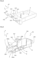
Fig. 4 ] représente une vue en perspective montrant le dessous d'une deuxième partie du dispositif de support de lafigure 1 , ladite deuxième partie étant constituée d'une pièce de soutien logée dans la goulotte de lafigure 3 ; - [
Fig. 5 ] représente une vue d'en haut du dispositif de support auquel est fixé le filtre à air ; - [
Fig. 6 ] représente une vue en perspective et une vue latérale de la pièce de soutien et d'un tuyau de dégazage monté sur ladite pièce ; - [
Fig. 7 ] représente une vue perspective et une vue d'en haut de la pièce de soutien comprenant des moyens de fixation avec un boîtier de fusibles et de relais; - [
Fig. 8 ] représente une vue en perspective du dispositif de support de lafigure 1 avec la batterie et un boîtier de fusibles et de relais monté sur la pièce de soutien ; - [
Fig. 9 ] illustre un agencement existant d'un filtre àair 3 avec un bac desupport 100 de batterie.
- [
Fig. 1 ] shows a front view of a support device according to the invention, said device receiving a battery and being connected to an air filter; - [
Fig. 2 ] represents a perspective view showing a front face of the support device of thefigure 1 ; - [
Fig.3 ] represents a perspective view showing the rear of a first part of the support device of thefigure 1 , said first part comprising a bottom, a perimeter extending vertically from the bottom and a chute; - [
Fig. 4 ] represents a perspective view showing the underside of a second part of the support device of thefigure 1 , said second part consisting of a support piece housed in the chute of thepicture 3 - [
Fig. 5 ] shows a top view of the support device to which the air filter is attached; - [
Fig. 6 ] shows a perspective view and a side view of the support part and of a degassing pipe mounted on said part; - [
Fig. 7 ] shows a perspective view and a view from above of the support part comprising fixing means with a fuse and relay box; - [
Fig. 8 ] shows a perspective view of the support device of thefigure 1 with the battery and a fuse and relay box mounted on the support piece; - [
Fig. 9 ] illustrates an existing arrangement of anair filter 3 with abattery holder 100.
Les éléments structurellement et fonctionnellement identiques, présents dans plusieurs figures distinctes, sont affectés d'une seule et même référence numérique ou alphanumérique.The structurally and functionally identical elements, present in several distinct figures, are assigned a single and same numerical or alphanumeric reference.
Dans la suite de la description, on adoptera une direction verticale représentée par l'axe V, une direction transversale horizontale ou latérale horizontale représentée par l'axe T et une direction longitudinale horizontale représentée par l'axe L. Ces trois axes sont illustrés sur les
En référence aux
Selon l'invention et comme dans cet exemple, le dispositif de support 1 comprend un fond 11 sur lequel est reposée la batterie 2, et plusieurs parois s'étendant verticalement à partir du fond 11. Les parois verticales forment un pourtour 12 entourant une partie inférieure de la batterie 122.According to the invention and as in this example, the
Pour faciliter la compréhension de l'invention, nous considérons que le fond 11 du bac de support est allongé suivant l'axe horizontal longitudinal L. Le fond 11 s'étend en largeur selon l'axe transversal horizontal T et qui est perpendiculaire à l'axe L. Les parois du pourtour 12 s'étendent depuis le fond 11 selon l'axe vertical V qui est perpendiculaire à l'axe horizontal longitudinal L ainsi qu'à l'axe transversal T de sorte que ces trois axes L, V, T forment un repère orthogonal direct tel qu'illustré sur les
Ici, le fond 11 et le pourtour 12 forme un bac de support 10.Here, the bottom 11 and the
Le dispositif de support 1 comprend en outre une goulotte 15 s'étendent horizontalement à partir d'un premier bord périphérique du fond 11. Ici, le premier bord périphérique est un bord latéral 111 du fond 11.The
Une plaque de fixation 151 est disposée à une première extrémité longitudinale 15a de la goulotte 15. La plaque de fixation 151 comprend, ici, un trou fileté 152 qui trouvera face à face d'un trou fileté porté par le filtre à air 3 lorsque ce dernier est attaché au dispositif de support 1. Une vis 31, illustrée sur la
Le poids du filtre à air 3, ainsi suspendu, exerce un effort au niveau de la vis 31 telle qu'illustrée par la flèche F1 sur la
Selon l'invention et comme dans cet exemple, la goulotte 15 et le bac de support 10 sont formés en une seule pièce. Autrement dit, le support de filtre à air, ici réalisé par la goulotte 15, est intégré au bac de support 10, ce qui permet de réduire le nombre de pièces distinctes de l'ensemble et l'incertitude dans le positionnement du filtre à air 3 par rapport au dispositif de support 1.According to the invention and as in this example, the
Grâce à l'intégration de la goulotte 15 au bac de support 10, le nombre de maillons de la chaîne de côte est réduit. En effet, comme observé sur la
Avec au moins un maillon en moins, la gestion de l'isostatisme de la zone entre la fixation du filtre à air 3 et la fixation du bac de support 10 à la structure de carrosserie est ainsi simplifiée.With at least one link less, the management of the isostatism of the zone between the fixing of the
Sur les
La
La pièce de soutien 16, agencée dans la goulotte 15, présente donc un premier côté latéral 161 qui s'oriente vers le filtre à air 3 et un deuxième côté latéral 162 qui s'oriente vers le bac de support 10.The
La pièce de soutien 16 comprend également les moyens de fixations avec le bac de support 10, ou plus précisément avec le pourtour 12 du bac de support 10. Dans l'exemple illustré, ces moyens de fixation sont agencés tous du deuxième côté latéral 162.The
Sur le deuxième côté latéral 162, la pièce de soutien 16 comprend une paroi primaire 163 et une paroi secondaire 164 s'étendant parallèlement l'une à l'autre et séparée latéralement l'une de l'autre par un espace E. Décrit autrement, la paroi primaire 163, la paroi secondaire 164 et une paroi supérieure 165 délimitent une rainure 166 ouverte en bas. L'espace E ou la rainure 166 reçoit une première paroi 121 qui s'étend verticalement à partir du premier bord périphérique 111 du fond 11.On the second
Une fois que la première paroi 121 se loge dans l'espace E ou la rainure 166, les parois primaires et secondaires 163 et 164 se trouvent de part et d'autre de la première paroi 121. Précisément, la paroi primaire 163 se trouve à l'extérieur d'un espace S délimité par le fond 11 et le pourtour 12 tandis que la paroi secondaire 164 se trouve à l'intérieur de cet espace S. La paroi primaire 163 est encore appelée paroi externe 163 et la paroi secondaire 164 paroi interne.Once the
Dans l'exemple illustré, la pièce de soutien 16 est agencée de manière à ce que l'espace E entre les parois primaires et secondaires 163, 164 présente une largeur e1 égale ou légèrement supérieure à la largeur e2 de la première paroi 121. De cette manière, la première paroi 121 et la rainure 166 s'emboîtent bien l'une dans l'autre pour d'une part maintenir fermement la pièce de soutien 16 en place dans la goulotte 15 et d'autre part éviter des déplacements latéraux de la pièce de soutien 16 par rapport au dispositif de support 1.In the example illustrated, the
La pièce de soutien 16 comprend en outre une aile latérale 167 s'étendant perpendiculairement à un axe longitudinal L1 de ladite pièce. L'aile latérale 167 comportant un premier trou 168. L'aile latérale est agencée de manière à ce que lorsque la pièce de soutien 16 est introduite dans la goulotte, le premier trou 168 soit aligné axialement avec un deuxième trou 123 pratiqué sur une deuxième paroi 122 perpendiculaire à la première paroi 121. Un rivet ou une vis traverse les trous 168 et 123 pour fixer la pièce de soutien 16 à la deuxième paroi 122.The
Ainsi, la pièce de soutien 16 comprend un premier moyen de fixation avec le pourtour 12, précisément avec la première paroi 121, constitué d'un espace E ou d'une rainure 166 délimité(e) par les parois primaires et secondaires 163, 164 et par la paroi supérieure 165.Thus, the
La pièce de soutien 16 comprend en outre un deuxième moyen de fixation avec le pourtour 12, précisément avec la deuxième paroi 122, constitué d'un trou de fixation traversant 168.The
Sur la
De manière optionnelle, la pièce de soutien 16 est conçue pour réaliser d'autres fonctions pratiques telles que la protection un puits de vis réalisé dans le fond 11 du bac de support 10, l'agencement des câbles d'alimentation électrique et d'un tuyau de dégazage, et le support pour un boîtier de fusibles et de relais. Ces fonctions seront détaillées ci-après dans la description.Optionally, the
Comme observé sur la
Le puits de vis 17 est destiné à recevoir notamment des vis pour la fixation du bac de support 10 sur une structure de carrosserie de véhicule. Lorsqu'un choc du véhicule survient, il se peut que des fuites d'acide puissent avoir lieu dans le cas des batteries plomb-acide, ce qui entraîne un risque de corrosion des vis de fixation du bac de support et donc un risque de désolidarisation du bac de support avec la structure de carrosserie.The screw well 17 is intended to receive in particular screws for fixing the
Afin de protéger des vis de fixation en cas de fuite d'acide, un bouchon de protection 7 est monté sur la pièce de soutien 16 de façon à se trouver face à face du puits de vis 17 lorsque ladite pièce de soutien est montée dans la goulotte 15.In order to protect the fixing screws in the event of an acid leak, a
Précisément, le bouchon de protection 7 est installé à une extrémité libre de la paroi secondaire 164 de la pièce de soutien 16. Plus précisément, le bouchon de protection 7 s'étend parallèlement au fond 11 du bac de support 10 à partir d'une extrémité libre d'une portion concave 164a de la paroi secondaire 164. En effet, les parois primaire et secondaire 163 et 164 de la pièce de soutien comprennent également des portions concaves respectives 163a et 164a pour s'adapter à la portion concave 121a de la première paroi 121.Specifically, the
Le bouchon de protection 7 présente une section circulaire dont le diamètre est égal ou légèrement inférieur au diamètre du puits de vis 17 pour être emmanché dans ledit puits 17 et pour recouvrir presque la totalité, voire la totalité de l'ouverture du puits. De plus, la hauteur de la paroi secondaire 164 de la pièce de soutien 16 est dimensionnée de manière à ce que lorsque la pièce de soutien 16 est montée sur le pourtour 12, la face supérieure 70 du bouchon de protection 7 affleure la face supérieure 110 du fond 11. Ainsi, la planéité du fond 11 est respectée, ce qui permet une pose stable de la batterie 2 sur le fond 11.The
La pièce de soutien 16 peut également porter des câbles d'alimentation électrique servant par exemple à alimenter la boucle dynamique moteur. Comme observé sur la
Les câbles d'alimentation électrique, fixés à la pièce de soutien 16, se trouvent donc protégés en bas par la goulotte 15, en haut par la pièce de soutien 16 et sur le côté par les parois latérales de la pièce de soutien 16 et de la goulotte 15. Les câbles peuvent donc avoir un habillage fin, voire ne pas avoir d'habillage, ce qui permet de réduire les coûts de fabrication de ces câbles. Par ailleurs, la pièce de soutien 16 permet une indexation de câblage dans le compartiment moteur du véhicule.The power supply cables, fixed to the
De manière optionnelle, la pièce de soutien 16 propose un logement pour un tuyau de dégazage de la batterie. Comme illustré sur la
Selon une option de l'invention, la pièce de soutien 16 comprend des moyens de fixation et de positionnement d'un boîtier 4 de fusibles et de relais. Dans l'exemple illustré, les moyens de fixation et de positionnement sont constitués d'un îlot 41 et d'une plaque 42, ces deux éléments étant disposés face à face et s'étendant verticalement à partir de la face supérieure 165 de la pièce de soutien 16.According to an option of the invention, the
La distance d entre l'îlot 41 et la plaque 42 correspond ici à la longueur L du boîtier 4 de fusible et de relais. Par exemple, la distance d est légèrement supérieure à la longueur L2 du boîtier 4 de sorte que ledit boîtier puisse se poser entre l'îlot 41 et la plaque 42.The distance d between the
La plaque 42 a pour fonction de butée arrière empêchant le déplacement vers l'arrière du boîtier 4. Quant au l'îlot 42, il porte un moyen de fixation avec le boîtier 4, par exemple une fixation en queue d'aronde.The
Comme illustré sur la
Ainsi, selon la description ci-dessus, la pièce de soutien 16 réunit plusieurs fonctions en un seul élément. La pièce de soutien 16 peut être encore appelée une pièce multifonction permettant :
- la rigidification de la goulotte 15 qui supporte le filtre à
air 3 ; - la protection du puits de vis 7 ;
- l'intégration de la fonction de support du boîtier 4 de fusibles et de relais ;
- l'intégration de la fonction de fixation et d'indexation du tuyau de dégazage 29 de la
batterie 2 ; - l'intégration de la fonction de fixation des câbles d'alimentation électrique ; et
- la réduction du nombre de maillons de la chaîne de côte en intégrant plusieurs fonctions en une seule pièce.
- the stiffening of the
chute 15 which supports theair filter 3; - the protection of the screw well 7;
- the integration of the support function of the
box 4 of fuses and relays; - the integration of the fixing and indexing function of the
degassing pipe 29 of thebattery 2; - the integration of the function of fixing the power supply cables; And
- reducing the number of links in the side chain by integrating several functions in a single piece.
On comprendra que diverses modifications et/ou améliorations évidentes pour l'homme du métier peuvent être apportées aux différents modes de réalisation de l'invention décrits dans la présente description sans sortir du cadre de l'invention défini par les revendications annexées.It will be understood that various modifications and/or improvements obvious to those skilled in the art can be made to the various embodiments of the invention described in the present description without departing from the scope of the invention defined by the appended claims.
Claims (10)
- Battery support device (1) for a motor vehicle, comprising a support tray (10) intended to receive a battery (2), said tray (10) comprising a bottom (11) and at least one wall (121, 122) extending vertically from the bottom (11);
said device (1) being characterized in that it comprises:- a channel (15) extending, in a horizontal direction, from a peripheral edge (111) of the bottom (11) and comprising a means (152) for fastening to an air filter (3); and- a supporting part (16) housed in the channel (15) and fastened to said channel (15) on one side and to the at least one wall (121, 122) of the tray on the other side. - Device (1) according to Claim 1, characterized in that the fastening point for fastening the supporting part (16) to the channel (15) is situated in the vicinity of the means (152) for fastening to the air filter (3).
- Device (1) according to Claim 1 or Claim 2, characterized in that the supporting part (16) comprises a reinforcement (13) disposed in the vicinity of the means (152) for fastening to the air filter (3).
- Device (1) according to one of the preceding claims, characterized in that the channel (15) is formed integrally with the support tray (10).
- Device (1) according to one of Claims 1 to 3, characterized in that:- a first wall (121) extends vertically from a first peripheral edge (111) of the bottom (11);- the channel (16) likewise extends, in the horizontal direction, from said first peripheral edge (111);- the supporting part (16) comprises an external wall (163) and an internal wall (164) delimiting a space (E) that receives said first wall (121) so as to fasten said supporting part (16) to said first wall (121).
- Device (1) according to Claim 5, characterized in that:- the first wall (121) comprises a concave portion (121a) arranged so as to leave a screw well (7) uncovered;- the external wall (163) and the internal wall (164) of the supporting part (16) each comprise a corresponding concave portion (163a, 164a) situated next to the concave portion (121a) of the first wall (121).
- Device (1) according to one of the preceding claims, characterized in that:- a first wall (121) extends vertically from a first peripheral edge (111) of the bottom (11);- the channel (15) likewise extends, in the horizontal direction, from said first peripheral edge (111);- the supporting part (16) is fastened to a second wall (122) intersecting said first wall (121).
- Device (1) according to Claim 7, characterized in that the supporting part (16) is fastened to the second wall (122) by being screwed thereto.
- Assembly for fastening and arranging a battery in a motor vehicle compartment, comprising:- a device (1) according to one of the preceding claims;- a battery (2); and- an air filter (3).
- Motor vehicle, characterized in that it comprises the device according to one of Claims 1 to 8 or the assembly according to Claim 9.
Applications Claiming Priority (2)
| Application Number | Priority Date | Filing Date | Title |
|---|---|---|---|
| FR1871435A FR3088488B1 (en) | 2018-11-09 | 2018-11-09 | MOTOR VEHICLE BATTERY SUPPORT DEVICE |
| PCT/EP2019/078243 WO2020094359A1 (en) | 2018-11-09 | 2019-10-17 | Motor vehicle battery support device |
Publications (2)
| Publication Number | Publication Date |
|---|---|
| EP3878025A1 EP3878025A1 (en) | 2021-09-15 |
| EP3878025B1 true EP3878025B1 (en) | 2023-06-07 |
Family
ID=66166110
Family Applications (1)
| Application Number | Title | Priority Date | Filing Date |
|---|---|---|---|
| EP19786604.9A Active EP3878025B1 (en) | 2018-11-09 | 2019-10-17 | Motor vehicle battery support device |
Country Status (6)
| Country | Link |
|---|---|
| EP (1) | EP3878025B1 (en) |
| JP (1) | JP7438208B2 (en) |
| KR (1) | KR20210088602A (en) |
| CN (1) | CN113169407A (en) |
| FR (1) | FR3088488B1 (en) |
| WO (1) | WO2020094359A1 (en) |
Family Cites Families (12)
| Publication number | Priority date | Publication date | Assignee | Title |
|---|---|---|---|---|
| FR2765158B1 (en) * | 1997-06-26 | 1999-09-10 | Oldham France Sa | SUPPORT FOR ELECTRICAL ACCUMULATOR BATTERY ASSEMBLY FOR A MOTOR VEHICLE |
| FR2778884B1 (en) * | 1998-05-19 | 2000-08-04 | Coutier Moulage Gen Ind | TRAY FOR SUPPORTING COMPONENTS OF THE MOTORIZATION OF A MOTOR VEHICLE |
| AT410308B (en) * | 2001-04-03 | 2003-03-25 | Man Sonderfahrzeuge Ag | TRUCKS WITH A NUMBER OF VEHICLE PARTS OR COMBINED IN A COMPACT ASSEMBLY BEHIND THE CAB. aggregates |
| JP3961239B2 (en) * | 2001-06-18 | 2007-08-22 | 日野自動車株式会社 | Battery support device for vehicle |
| FR2843340B1 (en) * | 2002-08-12 | 2005-04-01 | Renault Sa | DEVICE FOR FASTENING A COMBUSTION ENGINE AIR FILTER AND METHOD OF MOUNTING |
| SE528899C2 (en) * | 2004-11-16 | 2007-03-13 | Saab Automobile | Battery unit as well as vehicles equipped with such a battery unit |
| JP5326416B2 (en) | 2008-08-08 | 2013-10-30 | 日産自動車株式会社 | Body shock absorbing structure and mounting bracket for automotive parts |
| CA2753112C (en) * | 2009-02-24 | 2013-10-01 | Nissan Motor Co., Ltd. | Vehicle battery mounting structure |
| JP5387072B2 (en) | 2009-03-13 | 2014-01-15 | 日産自動車株式会社 | Battery support structure |
| JP5878048B2 (en) * | 2012-03-16 | 2016-03-08 | 本田技研工業株式会社 | Battery unit |
| CN203372169U (en) * | 2013-07-19 | 2014-01-01 | 重庆长安汽车股份有限公司 | Plastic tray of automobile storage battery |
| FR3045533B1 (en) * | 2015-12-22 | 2019-10-04 | Renault S.A.S. | "ASSEMBLY FOR THE ARRANGEMENT AND FIXING OF ELEMENTS IN THE ENGINE COMPARTMENT OF A MOTOR VEHICLE" |
-
2018
- 2018-11-09 FR FR1871435A patent/FR3088488B1/en active Active
-
2019
- 2019-10-17 EP EP19786604.9A patent/EP3878025B1/en active Active
- 2019-10-17 KR KR1020217015899A patent/KR20210088602A/en not_active Application Discontinuation
- 2019-10-17 JP JP2021524275A patent/JP7438208B2/en active Active
- 2019-10-17 CN CN201980076669.XA patent/CN113169407A/en active Pending
- 2019-10-17 WO PCT/EP2019/078243 patent/WO2020094359A1/en unknown
Also Published As
| Publication number | Publication date |
|---|---|
| EP3878025A1 (en) | 2021-09-15 |
| FR3088488B1 (en) | 2020-11-27 |
| JP2022506714A (en) | 2022-01-17 |
| FR3088488A1 (en) | 2020-05-15 |
| WO2020094359A1 (en) | 2020-05-14 |
| CN113169407A (en) | 2021-07-23 |
| JP7438208B2 (en) | 2024-02-26 |
| KR20210088602A (en) | 2021-07-14 |
Similar Documents
| Publication | Publication Date | Title |
|---|---|---|
| EP2595857B1 (en) | Car frame with a bracket for fixing a body part and wires to the main floor | |
| EP3310604B1 (en) | Battery-supporting arrangement for a hybrid vehicle | |
| EP3359405A1 (en) | Battery support arrangement for hybrid vehicle | |
| EP3878025B1 (en) | Motor vehicle battery support device | |
| WO2014195648A1 (en) | Connection plate for a motor vehicle having an electric or hybrid electric engine | |
| WO2020007651A1 (en) | Arrangement of a body understructure of a vehicle integrating a battery assembly and vehicle having such an arrangement | |
| EP3630550B1 (en) | Windscreen lower crossmember and front bulkhead soundproofing cover retention device | |
| EP4028273B1 (en) | Power supply assembly for a motor vehicle | |
| FR3081085A1 (en) | ELECTRICAL SAFETY AND CABLE CONNECTION BOX (S) COMPRISING A PYROTECHNIC DEVICE AND FUSES | |
| EP4304901A1 (en) | Device for supporting a motor vehicle battery charger | |
| FR3111597A1 (en) | Motor vehicle front bumper shock absorber | |
| FR2722755A1 (en) | Mounting structure for mounting of electrical equipment and battery on motor scooter | |
| FR3067298B1 (en) | ASSEMBLY FOR HYBRID VEHICLE CHASSIS FACILITATING ACCESS TO A RESERVOIR | |
| FR3074452B1 (en) | ASSEMBLY FOR HYBRID VEHICLE CHASSIS FACILITATING ACCESS TO A RESERVOIR | |
| WO2012035253A2 (en) | Motor vehicle comprising a battery mounted on the structure of the vehicle and means of connection between the upper portion of the battery and the associated battery structure | |
| EP3960544A1 (en) | Vehicle provided with a fairing under the fuel tank | |
| FR3130699A1 (en) | Device for holding at least one energy storage element arranged under the floor of a motor vehicle | |
| EP1291544B1 (en) | Anti-vibration support and vehicle with such a support | |
| FR3102434A1 (en) | Motor vehicle comprising a battery, and a battery fixing system | |
| FR2946950A1 (en) | Motor vehicle e.g. hybrid/electric vehicle, has power supply module arranged so as to traverse openings formed in floor pan, where module has part placed above surface of floor pan and another part placed under level of floor pan | |
| FR3131983A1 (en) | DEVICE FOR FIXING AN ELECTRIC BATTERY WITHIN A VEHICLE | |
| FR3125475A1 (en) | Electric motor vehicle with exchangeable storage battery | |
| WO2020049140A1 (en) | Arrangement of a vehicle body, comprising a device for attaching at least one conduit for energy storage | |
| FR3121890A1 (en) | Arrangement comprising protection for a vehicle fuse box. | |
| FR3010959A1 (en) | FRONT STRUCTURE OF A MOTOR VEHICLE WITH AN IMPROVED POWER SUPPLY CABLE ROUTE |
Legal Events
| Date | Code | Title | Description |
|---|---|---|---|
| STAA | Information on the status of an ep patent application or granted ep patent |
Free format text: STATUS: UNKNOWN |
|
| STAA | Information on the status of an ep patent application or granted ep patent |
Free format text: STATUS: THE INTERNATIONAL PUBLICATION HAS BEEN MADE |
|
| PUAI | Public reference made under article 153(3) epc to a published international application that has entered the european phase |
Free format text: ORIGINAL CODE: 0009012 |
|
| STAA | Information on the status of an ep patent application or granted ep patent |
Free format text: STATUS: REQUEST FOR EXAMINATION WAS MADE |
|
| 17P | Request for examination filed |
Effective date: 20210511 |
|
| AK | Designated contracting states |
Kind code of ref document: A1 Designated state(s): AL AT BE BG CH CY CZ DE DK EE ES FI FR GB GR HR HU IE IS IT LI LT LU LV MC MK MT NL NO PL PT RO RS SE SI SK SM TR |
|
| DAV | Request for validation of the european patent (deleted) | ||
| DAX | Request for extension of the european patent (deleted) | ||
| RAP3 | Party data changed (applicant data changed or rights of an application transferred) |
Owner name: RENAULT S.A.S |
|
| RAP3 | Party data changed (applicant data changed or rights of an application transferred) |
Owner name: RENAULT S.A.S |
|
| REG | Reference to a national code |
Ref country code: DE Ref legal event code: R079 Ref document number: 602019030483 Country of ref document: DE Free format text: PREVIOUS MAIN CLASS: H01M0002100000 Ipc: H01M0050200000 |
|
| GRAP | Despatch of communication of intention to grant a patent |
Free format text: ORIGINAL CODE: EPIDOSNIGR1 |
|
| STAA | Information on the status of an ep patent application or granted ep patent |
Free format text: STATUS: GRANT OF PATENT IS INTENDED |
|
| RIC1 | Information provided on ipc code assigned before grant |
Ipc: H01M 50/249 20210101ALI20221206BHEP Ipc: B60L 50/64 20190101ALI20221206BHEP Ipc: B60R 16/04 20060101ALI20221206BHEP Ipc: H01M 50/20 20210101AFI20221206BHEP |
|
| INTG | Intention to grant announced |
Effective date: 20230105 |
|
| GRAS | Grant fee paid |
Free format text: ORIGINAL CODE: EPIDOSNIGR3 |
|
| GRAA | (expected) grant |
Free format text: ORIGINAL CODE: 0009210 |
|
| STAA | Information on the status of an ep patent application or granted ep patent |
Free format text: STATUS: THE PATENT HAS BEEN GRANTED |
|
| AK | Designated contracting states |
Kind code of ref document: B1 Designated state(s): AL AT BE BG CH CY CZ DE DK EE ES FI FR GB GR HR HU IE IS IT LI LT LU LV MC MK MT NL NO PL PT RO RS SE SI SK SM TR |
|
| REG | Reference to a national code |
Ref country code: GB Ref legal event code: FG4D Free format text: NOT ENGLISH |
|
| REG | Reference to a national code |
Ref country code: CH Ref legal event code: EP Ref country code: AT Ref legal event code: REF Ref document number: 1577655 Country of ref document: AT Kind code of ref document: T Effective date: 20230615 |
|
| REG | Reference to a national code |
Ref country code: DE Ref legal event code: R096 Ref document number: 602019030483 Country of ref document: DE |
|
| P01 | Opt-out of the competence of the unified patent court (upc) registered |
Effective date: 20230608 |
|
| REG | Reference to a national code |
Ref country code: LT Ref legal event code: MG9D |
|
| REG | Reference to a national code |
Ref country code: NL Ref legal event code: MP Effective date: 20230607 |
|
| PG25 | Lapsed in a contracting state [announced via postgrant information from national office to epo] |
Ref country code: SE Free format text: LAPSE BECAUSE OF FAILURE TO SUBMIT A TRANSLATION OF THE DESCRIPTION OR TO PAY THE FEE WITHIN THE PRESCRIBED TIME-LIMIT Effective date: 20230607 Ref country code: NO Free format text: LAPSE BECAUSE OF FAILURE TO SUBMIT A TRANSLATION OF THE DESCRIPTION OR TO PAY THE FEE WITHIN THE PRESCRIBED TIME-LIMIT Effective date: 20230907 Ref country code: ES Free format text: LAPSE BECAUSE OF FAILURE TO SUBMIT A TRANSLATION OF THE DESCRIPTION OR TO PAY THE FEE WITHIN THE PRESCRIBED TIME-LIMIT Effective date: 20230607 |
|
| REG | Reference to a national code |
Ref country code: AT Ref legal event code: MK05 Ref document number: 1577655 Country of ref document: AT Kind code of ref document: T Effective date: 20230607 |
|
| PG25 | Lapsed in a contracting state [announced via postgrant information from national office to epo] |
Ref country code: RS Free format text: LAPSE BECAUSE OF FAILURE TO SUBMIT A TRANSLATION OF THE DESCRIPTION OR TO PAY THE FEE WITHIN THE PRESCRIBED TIME-LIMIT Effective date: 20230607 Ref country code: NL Free format text: LAPSE BECAUSE OF FAILURE TO SUBMIT A TRANSLATION OF THE DESCRIPTION OR TO PAY THE FEE WITHIN THE PRESCRIBED TIME-LIMIT Effective date: 20230607 Ref country code: LV Free format text: LAPSE BECAUSE OF FAILURE TO SUBMIT A TRANSLATION OF THE DESCRIPTION OR TO PAY THE FEE WITHIN THE PRESCRIBED TIME-LIMIT Effective date: 20230607 Ref country code: LT Free format text: LAPSE BECAUSE OF FAILURE TO SUBMIT A TRANSLATION OF THE DESCRIPTION OR TO PAY THE FEE WITHIN THE PRESCRIBED TIME-LIMIT Effective date: 20230607 Ref country code: HR Free format text: LAPSE BECAUSE OF FAILURE TO SUBMIT A TRANSLATION OF THE DESCRIPTION OR TO PAY THE FEE WITHIN THE PRESCRIBED TIME-LIMIT Effective date: 20230607 Ref country code: GR Free format text: LAPSE BECAUSE OF FAILURE TO SUBMIT A TRANSLATION OF THE DESCRIPTION OR TO PAY THE FEE WITHIN THE PRESCRIBED TIME-LIMIT Effective date: 20230908 |
|
| PG25 | Lapsed in a contracting state [announced via postgrant information from national office to epo] |
Ref country code: FI Free format text: LAPSE BECAUSE OF FAILURE TO SUBMIT A TRANSLATION OF THE DESCRIPTION OR TO PAY THE FEE WITHIN THE PRESCRIBED TIME-LIMIT Effective date: 20230607 |
|
| PG25 | Lapsed in a contracting state [announced via postgrant information from national office to epo] |
Ref country code: SK Free format text: LAPSE BECAUSE OF FAILURE TO SUBMIT A TRANSLATION OF THE DESCRIPTION OR TO PAY THE FEE WITHIN THE PRESCRIBED TIME-LIMIT Effective date: 20230607 |
|
| PGFP | Annual fee paid to national office [announced via postgrant information from national office to epo] |
Ref country code: GB Payment date: 20231020 Year of fee payment: 5 |
|
| PG25 | Lapsed in a contracting state [announced via postgrant information from national office to epo] |
Ref country code: IS Free format text: LAPSE BECAUSE OF FAILURE TO SUBMIT A TRANSLATION OF THE DESCRIPTION OR TO PAY THE FEE WITHIN THE PRESCRIBED TIME-LIMIT Effective date: 20231007 |
|
| PG25 | Lapsed in a contracting state [announced via postgrant information from national office to epo] |
Ref country code: SM Free format text: LAPSE BECAUSE OF FAILURE TO SUBMIT A TRANSLATION OF THE DESCRIPTION OR TO PAY THE FEE WITHIN THE PRESCRIBED TIME-LIMIT Effective date: 20230607 Ref country code: SK Free format text: LAPSE BECAUSE OF FAILURE TO SUBMIT A TRANSLATION OF THE DESCRIPTION OR TO PAY THE FEE WITHIN THE PRESCRIBED TIME-LIMIT Effective date: 20230607 Ref country code: RO Free format text: LAPSE BECAUSE OF FAILURE TO SUBMIT A TRANSLATION OF THE DESCRIPTION OR TO PAY THE FEE WITHIN THE PRESCRIBED TIME-LIMIT Effective date: 20230607 Ref country code: PT Free format text: LAPSE BECAUSE OF FAILURE TO SUBMIT A TRANSLATION OF THE DESCRIPTION OR TO PAY THE FEE WITHIN THE PRESCRIBED TIME-LIMIT Effective date: 20231009 Ref country code: IS Free format text: LAPSE BECAUSE OF FAILURE TO SUBMIT A TRANSLATION OF THE DESCRIPTION OR TO PAY THE FEE WITHIN THE PRESCRIBED TIME-LIMIT Effective date: 20231007 Ref country code: EE Free format text: LAPSE BECAUSE OF FAILURE TO SUBMIT A TRANSLATION OF THE DESCRIPTION OR TO PAY THE FEE WITHIN THE PRESCRIBED TIME-LIMIT Effective date: 20230607 Ref country code: CZ Free format text: LAPSE BECAUSE OF FAILURE TO SUBMIT A TRANSLATION OF THE DESCRIPTION OR TO PAY THE FEE WITHIN THE PRESCRIBED TIME-LIMIT Effective date: 20230607 Ref country code: AT Free format text: LAPSE BECAUSE OF FAILURE TO SUBMIT A TRANSLATION OF THE DESCRIPTION OR TO PAY THE FEE WITHIN THE PRESCRIBED TIME-LIMIT Effective date: 20230607 |
|
| PGFP | Annual fee paid to national office [announced via postgrant information from national office to epo] |
Ref country code: FR Payment date: 20231026 Year of fee payment: 5 Ref country code: DE Payment date: 20231020 Year of fee payment: 5 |
|
| PG25 | Lapsed in a contracting state [announced via postgrant information from national office to epo] |
Ref country code: PL Free format text: LAPSE BECAUSE OF FAILURE TO SUBMIT A TRANSLATION OF THE DESCRIPTION OR TO PAY THE FEE WITHIN THE PRESCRIBED TIME-LIMIT Effective date: 20230607 |
|
| REG | Reference to a national code |
Ref country code: DE Ref legal event code: R097 Ref document number: 602019030483 Country of ref document: DE |
|
| PLBE | No opposition filed within time limit |
Free format text: ORIGINAL CODE: 0009261 |
|
| STAA | Information on the status of an ep patent application or granted ep patent |
Free format text: STATUS: NO OPPOSITION FILED WITHIN TIME LIMIT |
|
| PG25 | Lapsed in a contracting state [announced via postgrant information from national office to epo] |
Ref country code: DK Free format text: LAPSE BECAUSE OF FAILURE TO SUBMIT A TRANSLATION OF THE DESCRIPTION OR TO PAY THE FEE WITHIN THE PRESCRIBED TIME-LIMIT Effective date: 20230607 |
|
| PG25 | Lapsed in a contracting state [announced via postgrant information from national office to epo] |
Ref country code: SI Free format text: LAPSE BECAUSE OF FAILURE TO SUBMIT A TRANSLATION OF THE DESCRIPTION OR TO PAY THE FEE WITHIN THE PRESCRIBED TIME-LIMIT Effective date: 20230607 |
|
| 26N | No opposition filed |
Effective date: 20240308 |