EP3310604B1 - Battery-supporting arrangement for a hybrid vehicle - Google Patents
Battery-supporting arrangement for a hybrid vehicle Download PDFInfo
- Publication number
- EP3310604B1 EP3310604B1 EP16739199.4A EP16739199A EP3310604B1 EP 3310604 B1 EP3310604 B1 EP 3310604B1 EP 16739199 A EP16739199 A EP 16739199A EP 3310604 B1 EP3310604 B1 EP 3310604B1
- Authority
- EP
- European Patent Office
- Prior art keywords
- supporting element
- battery
- rear floor
- arrangement according
- body rear
- Prior art date
- Legal status (The legal status is an assumption and is not a legal conclusion. Google has not performed a legal analysis and makes no representation as to the accuracy of the status listed.)
- Active
Links
Images

Classifications
-
- B—PERFORMING OPERATIONS; TRANSPORTING
- B60—VEHICLES IN GENERAL
- B60K—ARRANGEMENT OR MOUNTING OF PROPULSION UNITS OR OF TRANSMISSIONS IN VEHICLES; ARRANGEMENT OR MOUNTING OF PLURAL DIVERSE PRIME-MOVERS IN VEHICLES; AUXILIARY DRIVES FOR VEHICLES; INSTRUMENTATION OR DASHBOARDS FOR VEHICLES; ARRANGEMENTS IN CONNECTION WITH COOLING, AIR INTAKE, GAS EXHAUST OR FUEL SUPPLY OF PROPULSION UNITS IN VEHICLES
- B60K1/00—Arrangement or mounting of electrical propulsion units
- B60K1/04—Arrangement or mounting of electrical propulsion units of the electric storage means for propulsion
- B60K2001/0405—Arrangement or mounting of electrical propulsion units of the electric storage means for propulsion characterised by their position
- B60K2001/0416—Arrangement in the rear part of the vehicle
-
- B—PERFORMING OPERATIONS; TRANSPORTING
- B60—VEHICLES IN GENERAL
- B60K—ARRANGEMENT OR MOUNTING OF PROPULSION UNITS OR OF TRANSMISSIONS IN VEHICLES; ARRANGEMENT OR MOUNTING OF PLURAL DIVERSE PRIME-MOVERS IN VEHICLES; AUXILIARY DRIVES FOR VEHICLES; INSTRUMENTATION OR DASHBOARDS FOR VEHICLES; ARRANGEMENTS IN CONNECTION WITH COOLING, AIR INTAKE, GAS EXHAUST OR FUEL SUPPLY OF PROPULSION UNITS IN VEHICLES
- B60K1/00—Arrangement or mounting of electrical propulsion units
- B60K1/04—Arrangement or mounting of electrical propulsion units of the electric storage means for propulsion
- B60K2001/0455—Removal or replacement of the energy storages
- B60K2001/0466—Removal or replacement of the energy storages from above
-
- B—PERFORMING OPERATIONS; TRANSPORTING
- B62—LAND VEHICLES FOR TRAVELLING OTHERWISE THAN ON RAILS
- B62D—MOTOR VEHICLES; TRAILERS
- B62D43/00—Spare wheel stowing, holding, or mounting arrangements
- B62D43/06—Spare wheel stowing, holding, or mounting arrangements within the vehicle body
- B62D43/10—Spare wheel stowing, holding, or mounting arrangements within the vehicle body and arranged substantially horizontally
Description
La présente invention concerne un agencement de support d'une batterie d'alimentation d'une machine électrique embarquée dans un véhicule automobile hybride.The present invention relates to a support arrangement of a battery for powering an electric machine on board a hybrid motor vehicle.
On connaît certains véhicules de type véhicule hybride (véhicules dits HEV « Hybrid Electric Véhiculé » ou PHEV « Plug-in Hybrid Electric Vehicle » en terminologie anglo-saxonne), qui comprennent un petit dispositif électrique, désigné par l'acronyme anglais « SED » (pour « Small Electric Device »).There are certain vehicles of the hybrid vehicle type (vehicles called HEV "Hybrid Electric Vehicle" or PHEV "Plug-in Hybrid Electric Vehicle" in English terminology), which include a small electrical device, designated by the acronym "SED" (for "Small Electric Device").
Un tel petit dispositif électrique comprend une machine électrique embarquée dans le véhicule, qui peut réaliser une ou plusieurs des fonctions suivantes telle que apporter une puissance et un couple d'assistance au moteur thermique du véhicule, notamment dans les phases de démarrage, décollage et roulage, généralement à bas régime et/ou faible vitesse, ou encore apporter l'énergie nécessaire au redémarrage du moteur thermique après un arrêt temporaire (fonction appelée « stop and start » en terminologie anglo-saxonne).Such a small electrical device comprises an electrical machine embedded in the vehicle, which can perform one or more of the following functions such as providing power and assistance torque to the engine of the vehicle, especially in the start, takeoff and taxiing phases. , generally at low speed and / or low speed, or provide the energy necessary to restart the engine after a temporary stop (function called "stop and start" in English terminology).
On connaît des véhicules où le petit dispositif électrique est fixé dans une région en arrière du dossier de la banquette arrière du véhicule (rang 2), par exemple sur une partie avant du plancher arrière de la structure de caisse. Aussi, un tel petit dispositif électrique est alimenté en électricité par une batterie d'alimentation, typiquement une batterie 48 volts. Un volume doit donc être réservé pour l'intégration de la batterie en partie arrière du véhicule.Vehicles are known where the small electrical device is fixed in a region behind the backrest of the rear seat of the vehicle (rank 2), for example on a front portion of the rear floor of the body structure. Also, such a small electrical device is supplied with electricity by a battery pack, typically a 48 volts battery. A volume must be reserved for the integration of the battery at the rear of the vehicle.
D'autres agencements sont décrit dans les documents
Ce but est atteint grâce à un agencement de support selon la revendication 1.This object is achieved by a support arrangement according to
Selon d'autres caractéristiques avantageuses de l'agencement de support conforme à l'invention, prises isolément ou en combinaison :
- lesdits points de fixation sont agencés sur des parties latérales dudit élément de support situées de part et d'autre de ladite zone de réception de ladite batterie suivant l'axe longitudinal dudit élément de support ;
- lesdites parties latérales dudit élément de support comprennent des moyens de positionnement dudit élément de support relativement audit plancher arrière de caisse, notamment relativement à un plan longitudinal transversal dudit plancher arrière de caisse ;
- lesdits moyens de positionnement comprennent au moins un pion de positionnement s'étendant dans une direction sensiblement normale au plan dudit élément de support et apte à traverser un orifice correspondant ménagé sur ledit plancher arrière de caisse ;
- ledit élément de support comprend des moyens de fixation d'un carter de batterie et ledit élément de support comprend une barre de renfort longitudinale montée de manière amovible sur ledit élément de support et adaptée pour s'étendre en regard de ladite zone de réception de batterie, de manière à constituer un appui pour ledit carter de batterie en partie supérieure dudit carter de batterie ;
- ledit élément de support comprend une traverse longitudinale d'arrêt de charge adaptée à s'étendre transversalement dans le véhicule entre des bordures latérales dudit plancher arrière de caisse ;
- ladite traverse longitudinale d'arrêt de charge comprend un tube cintré fixé à chacune de ses extrémités audit élément de support ;
- une jambe de reprise d'effort est disposé à proximité de chacune des extrémités de ladite traverse longitudinale d'arrêt de charge, pour relier ladite traverse et ledit élément de support de part et d'autre de ladite zone de réception de ladite batterie ;
- il comprend moyens de fixation d'un groupe moto-ventilateur sur une partie latérale dudit élément de support.
- said attachment points are arranged on side portions of said support member located on either side of said receiving zone of said battery along the longitudinal axis of said support member;
- said lateral portions of said support member comprise means for positioning said support member relative to said rear deck floor, in particular relative to a transverse longitudinal plane of said rear deck floor;
- said positioning means comprise at least one positioning pin extending in a direction substantially normal to the plane of said support member and adapted to pass through a corresponding orifice formed on said rear floor of the body;
- said support member comprises battery case attachment means and said support member comprises a longitudinal reinforcing bar removably mounted on said support member and adapted to extend facing said battery receiving area. , so as to constitute a support for said battery case in the upper part of said battery case;
- said support member comprises a longitudinal load-arresting cross member adapted to extend transversely in the vehicle between side edges of said rear body floor;
- said longitudinal load-stop beam comprises a bent tube attached at each of its ends to said support member;
- a force recovery leg is disposed near each of the ends of said longitudinal load stop beam, for connecting said cross member and said support member on either side of said receiving zone of said battery;
- it comprises means for fixing a motor-fan unit on a lateral part of said support element.
D'autres particularités et avantages de l'invention ressortiront à la lecture de la description faite ci-après d'un mode de réalisation particulier de l'invention, donné à titre indicatif mais non limitatif, en référence aux figures annexées dans lesquelles :
- la
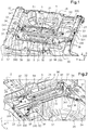
figure 1 représente une vue en perspective d'un agencement de support de batterie en partie arrière d'un véhicule selon un mode de réalisation de l'invention ; - la
figure 2 représente une vue en perspective opposée de l'agencement de support de batterie représenté à lafigure 1 ; - la
figure 3 est une vue éclatée de l'élément de support mis en oeuvre dans l'agencement de support représenté auxfigures 1 et 2 ; - la
figure 4 représente l'agencement de support de batterie de lafigure 1 , montré dans son environnement de montage.
- the
figure 1 is a perspective view of a battery support arrangement at the rear of a vehicle according to one embodiment of the invention; - the
figure 2 represents an opposite perspective view of the battery support arrangement shown in FIG.figure 1 ; - the
figure 3 is an exploded view of the support member implemented in the support arrangement shown in FIGS.Figures 1 and 2 ; - the
figure 4 represents the battery support arrangement of thefigure 1 , shown in its editing environment.
Dans la présente description, les termes avant, arrière, font référence aux directions avant et arrière du véhicule. Les axes X, Y, Z, correspondent respectivement à l'axe longitudinal (d'avant en arrière), transversal (orienté vers la droite) et vertical (orienté vers le haut) du véhicule.In the present description, the terms front, rear, refer to the front and rear directions of the vehicle. The X, Y, Z axes correspond respectively to the longitudinal axis (front to back), transverse (right) and vertical (upward) of the vehicle.
Les
Conformément à l'invention, l'agencement de support pour la batterie 1 comprend un élément de support 3 allongé sensiblement plan, s'étendant transversalement au plancher arrière de caisse 23, et fixé directement sur la plaque du plancher arrière de caisse 23 dans une région de ce dernier située immédiatement à l'avant et au-dessus du logement concave 24 de réception de roue de secours. Autrement dit, l'élément de support 3 est adapté à s'étendre transversalement sur le plancher arrière de caisse 23, de manière à être située à l'arrière d'une rangée d'au moins un dossier de siège d'une banquette passager arrière du véhicule et à l'avant du logement concave 24 de réception de la roue de secours.According to the invention, the support arrangement for the
L'élément de support 3 est préférentiellement constitué d'une pièce de tôlerie, sensiblement en forme de quadrilatère, obtenue par exemple par emboutissage.The
L'élément de support 3 comprend principalement une zone de réception 31, sensiblement centrale, destinée à accueillir et maintenir en place la batterie 1 sur l'élément de support 3 lorsque l'élément de support 3 est fixé sur le plancher arrière de caisse 23. Pour ce faire, la zone de réception de batterie 31 de l'élément de support 3 est équipée de moyens de maintien 32 de la batterie sur la zone de réception 31, se présentant par exemple sous la forme d'ergots de fixation s'étendant sensiblement verticalement vers le haut depuis une surface de la zone de réception 31 et destinés à être insérés dans des ouvertures de montage correspondantes de la batterie lorsque cette dernière est montée sur la zone de réception de batterie 31 de l'élément de support 3. A noter que dans un exemple de réalisation, la zone de réception de batterie 31 peut être partiellement ajourée, par exemple au moyen d'une ouverture sensiblement rectangulaire pratiquée dans la zone de réception de batterie, comme illustré sur les figures, de façon à optimiser la masse de l'élément de support 3, sans pour autant détériorer sa tenue mécanique.The
L'élément de support 3 comporte par ailleurs des parties latérales 33, 34 situées respectivement de part et d'autre de la zone de réception de batterie 31, suivant l'axe longitudinal de l'élément de support 3 (confondu avec l'axe transversal du véhicule lorsque l'élément de support est fixé sur le plancher arrière de caisse). Ces parties latérales 33, 34 de l'élément de support 3 sont pourvues de points de fixation 330, 340 destinés à être fixés au plancher arrière de caisse 23, de façon à permettre la fixation de l'élément de support 3 directement sur le plancher arrière de caisse 23. Selon l'exemple de réalisation illustré, on prévoit quatre points de fixation 330 sur le plancher arrière de caisse 23 répartis sur une première partie latérale 33 de l'élément de support 3 et deux points de fixation 340 sur le plancher arrière de caisse 23 répartis sur l'autre partie latérale 34, située à l'opposée de la première partie latérale 33 par rapport à la zone de réception de batterie 31. Ces points de fixation agencés au niveau des parties latérales de l'élément de support 3 autorisent une fixation suivant l'axe vertical de l'élément de support au plancher arrière de caisse, par exemple au moyen de vis de fixation coopérant avec des structures de fixation correspondantes agencées sur le plancher arrière de caisse. Les points de fixation agencés au niveau des parties latérales de l'élément de support sont répartis de manière à permettre la fixation sur et/ou à proximité immédiate des bordures latérales du plancher arrière de caisse.The
Les parties latérales 33, 34 de l'élément de support 3 comprennent en outre des moyens de positionnement 331, 341 destinés à permettre de positionner l'élément de support 3 et partant, la batterie montée dessus, relativement au plancher arrière de caisse 23 et notamment pour permettre son positionnement relativement au plan longitudinal transversal du plancher arrière de caisse 23. Selon l'exemple de réalisation, ces moyens de positionnement comprennent un pion de positionnement 331, 341 respectivement agencé sur chacune des deux parties latérales 33, 34. Ces pions de positionnement s'étendent dans une direction sensiblement normale au plan de l'élément de support 3 (sensiblement suivant l'axe vertical) et sont destinés à traverser un orifice correspondant ménagé sur le plancher arrière de caisse 23 lorsque l'élément de support est fixé au plancher arrière de caisse.The
Suivant un mode de réalisation de l'invention, l'élément de support 3 pour la batterie est conçu pour intégrer d'autres fonctions que celle visant à l'implantation et au maintien de la batterie au niveau de plancher arrière de caisse du véhicule, au-dessus et à l'avant du bac de réception de roue de secours.According to one embodiment of the invention, the
En particulier, suivant l'exemple de réalisation, l'élément de support 3 comprend des moyens de fixation 35 adaptés pour fixer un groupe moto-ventilateur sur l'élément de support 3. Un tel groupe moto-ventilateur est en effet nécessaire au refroidissement de la batterie 1. Pour ce faire, comme illustré en référence à la
L'élément de support 3 est en outre conçu pour assurer l'intégration de la fonction d'arrêt bagages dans le coffre du véhicule. Pour ce faire, l'élément de support 3 intègre une traverse longitudinale d'arrêt de charge 5, fixée sur l'élément de support 3, et adaptée à s'étendre transversalement dans le véhicule entre les bordures latérales du plancher arrière de caisse 23, lorsque l'élément de support 3 est fixé sur le plancher arrière de caisse. La traverse longitudinale d'arrêt de charge 5 est constitué par exemple d'un tube cintré 51 fixé au niveau de chacune de ses extrémités 52, 53 sur l'élément de support, en particulier sur les parties latérales respectives de l'élément de support. Avantageusement, des points de fixation 330, 340 de l'élément de support sur le plancher arrière de caisse peuvent être utilisés pour relier mécaniquement les extrémités 52, 53 du tube soudé 51 à l'élément de support.The
On prévoit en outre, à proximité de chacune des extrémités 52, 53 de la traverse longitudinale d'arrêt de charge 5, une jambe de reprise d'effort, respectivement 54, 55, s'étendant perpendiculairement à la traverse à l'opposé de la partie arrière du plancher arrière de caisse par rapport à la traverse et permettant de relier la traverse 5 et l'élément de support 3 de part et d'autre de la zone de réception 31 de la batterie. Les jambes de reprise d'effort 54, 55 permettant ainsi de reprendre les efforts s'exerçant sur la traverse 5 dans le sens longitudinal.In addition, near each of the
Selon l'exemple de réalisation, l'élément de support 3 comprend encore des moyens de fixation 36 aptes à permettre la fixation d'un carter de batterie (habillage autour de la batterie, non représenté). L'élément de support 3 comprend aussi préférentiellement une barre de renfort longitudinale 6 montée de manière amovible sur l'élément de support 3 et adaptée pour s'étendre transversalement sensiblement en regard de la zone de réception de batterie 31, de manière à constituer un appui pour le carter de batterie en partie supérieure du carter de batterie lorsque ce dernier est monté autour de la batterie sur l'élément de support. Selon l'exemple de réalisation, la barre de renfort longitudinale 6 du carter de batterie est montée à chacune de ses extrémités, par exemple par l'intermédiaire de vis de fixation, sur des pattes de support 56, 57 faisant saillie sensiblement verticalement des jambes de reprise d'effort 51, 55.According to the exemplary embodiment, the
Enfin, selon l'exemple de réalisation, l'élément de support 3 comprend des poignées de préhension 37, situées de part et d'autre de la zone de réception 31 de la batterie. Chacune de ces poignées de préhension 37 est par exemple constituée par un fil cintré formant un arceau, fixé à chacune de ses extrémités sur la surface de l'élément de support, de chaque côté de la zone de réception de batterie. Les poignées de préhension 37 ainsi fixées à l'élément de support sont adaptées pour coopérer avec un moyen d'assistance de montage pour la manutention et la mise en place de l'élément de support sur le plancher arrière de caisse. En particulier, un outil ayant la forme d'une fourche à deux longerons porteurs horizontaux destinés à coopérer avec les poignées de préhension 37 agencées de chaque côté de la zone de réception batterie de l'élément de support, peut être utilisé pour manutentionner l'élément de support, notamment pour soulever et installer ou déposer l'élément de support.Finally, according to the exemplary embodiment, the
L'intégration « tout en 1 » à l'élément de support 3 des diverses fonctions décrites ci-dessus permet de réaliser une préparation montage de l'ensemble en bord de chaine de montage, avant mise en place dans le véhicule. Cela facilite l'opération de montage et d'implantation de ces fonctions au sein du véhicule, et permet de conserver une bonne ergonomie en préparation en bord de chaine, plutôt que de multiples interventions à l'intérieur du véhicule.The "all-in-one" integration with the
Claims (9)
- Arrangement for supporting a battery (1) for powering an electric motor on-board a hybrid motor vehicle, including a body rear floor (23) provided with a concave recess (24) for receiving a spare wheel, the arrangement comprising a substantially planar elongate supporting element (3) including an area (31) for receiving said battery provided with means (32) for holding said battery on said supporting element, said supporting element (3) including points (330, 340) for fastening said supporting element to said body rear floor and extending transversely to said body rear floor immediately in front of and above said concave recess (24) for receiving a spare wheel, characterized in that said supporting element (3) includes grip handles (37) located on either side of the receiving area (31) for said battery, said grip handles (37) including an arch-shaped wire that is fastened to said supporting element (3) and that is designed to cooperate with assembly assistance means for handling and positioning said supporting element on said body rear floor.
- Supporting arrangement according to Claim 1, characterized in that said fastening points are arranged on lateral portions (33, 34) of said supporting element (3) that are located on either side of said receiving area (31) for said battery along the longitudinal axis of said supporting element (3).
- Arrangement according to Claim 2, characterized in that said lateral portions (33, 34) of said supporting element include means (331, 341) for positioning said supporting element (3) in relation to said body rear floor (23), notably in relation to a transverse longitudinal plane of said body rear floor.
- Arrangement according to Claim 3, characterized in that said positioning means (331, 341) include at least one positioning pin that extends in a direction substantially normal to the plane of said supporting element and that is designed to pass through a corresponding aperture formed in said body rear floor.
- Arrangement according to any one of the preceding claims, characterized in that said supporting element (3) includes means (36) for fastening a battery casing and in that said supporting element includes a longitudinal reinforcing bar (6) that is mounted removably on said supporting element (3) and that is designed to extend opposite said battery receiving area (31) such as to form a support for said battery casing at the upper portion of said battery casing.
- Arrangement according to any one of the preceding claims, characterized in that said supporting element (3) includes a longitudinal load-arresting cross member (5) that is designed to extend transversely in the vehicle between lateral edges of said body rear floor.
- Arrangement according to Claim 6, characterized in that said longitudinal load-arresting cross member (5) includes a curved tube (51) fastened at each end (52, 53) to said supporting element (3).
- Arrangement according to either one of Claims 6 and 7, characterized in that it includes a force absorbing strut (54, 55) close to each of the ends of said longitudinal load-arresting cross member (5) to link said cross member (5) and said supporting element (3) on either side of said receiving area (31) for said battery.
- Arrangement according to any one of the preceding claims, characterized in that it includes means for fastening a fan unit to a lateral portion of said supporting element.
Applications Claiming Priority (2)
| Application Number | Priority Date | Filing Date | Title |
|---|---|---|---|
| FR1555635A FR3037539B1 (en) | 2015-06-19 | 2015-06-19 | BATTERY SUPPORT ARRANGEMENT FOR A HYBRID VEHICLE. |
| PCT/FR2016/051334 WO2016203130A1 (en) | 2015-06-19 | 2016-06-03 | Battery-supporting arrangement for a hybrid vehicle |
Publications (2)
| Publication Number | Publication Date |
|---|---|
| EP3310604A1 EP3310604A1 (en) | 2018-04-25 |
| EP3310604B1 true EP3310604B1 (en) | 2019-08-07 |
Family
ID=54145840
Family Applications (1)
| Application Number | Title | Priority Date | Filing Date |
|---|---|---|---|
| EP16739199.4A Active EP3310604B1 (en) | 2015-06-19 | 2016-06-03 | Battery-supporting arrangement for a hybrid vehicle |
Country Status (5)
| Country | Link |
|---|---|
| EP (1) | EP3310604B1 (en) |
| JP (1) | JP6722704B2 (en) |
| CN (1) | CN107848387B (en) |
| FR (1) | FR3037539B1 (en) |
| WO (1) | WO2016203130A1 (en) |
Families Citing this family (12)
| Publication number | Priority date | Publication date | Assignee | Title |
|---|---|---|---|---|
| US10632857B2 (en) | 2016-08-17 | 2020-04-28 | Shape Corp. | Battery support and protection structure for a vehicle |
| CN110383526A (en) | 2017-01-04 | 2019-10-25 | 形状集团 | The Vehicular battery support holder structure of node module |
| US10483510B2 (en) | 2017-05-16 | 2019-11-19 | Shape Corp. | Polarized battery tray for a vehicle |
| US11211656B2 (en) | 2017-05-16 | 2021-12-28 | Shape Corp. | Vehicle battery tray with integrated battery retention and support feature |
| WO2018213306A1 (en) | 2017-05-16 | 2018-11-22 | Shape Corp. | Vehicle battery tray having tub-based component |
| WO2019055658A2 (en) | 2017-09-13 | 2019-03-21 | Shape Corp. | Vehicle battery tray with tubular peripheral wall |
| CN111201155A (en) | 2017-10-04 | 2020-05-26 | 形状集团 | Battery tray bottom plate assembly for electric vehicle |
| CN112055898A (en) | 2018-03-01 | 2020-12-08 | 形状集团 | Cooling system integrated with vehicle battery tray |
| US11688910B2 (en) | 2018-03-15 | 2023-06-27 | Shape Corp. | Vehicle battery tray having tub-based component |
| FR3086893B1 (en) * | 2018-10-03 | 2020-11-20 | Renault Sas | KINETIC ENERGY ABSORPTION DEVICE FOR PROTECTION AGAINST IMPACT OF A MOTOR VEHICLE BATTERY |
| FR3093031B1 (en) * | 2019-02-27 | 2021-02-19 | Psa Automobiles Sa | Adapter plate for a battery on a support member |
| FR3104123A1 (en) * | 2019-12-06 | 2021-06-11 | Renault S.A.S | Floor with battery protection under the front seat. |
Family Cites Families (10)
| Publication number | Priority date | Publication date | Assignee | Title |
|---|---|---|---|---|
| JP4221998B2 (en) * | 2002-10-28 | 2009-02-12 | スズキ株式会社 | Electric equipment fixing structure of vehicle |
| JP4687015B2 (en) * | 2004-06-23 | 2011-05-25 | トヨタ自動車株式会社 | Power supply |
| FR2934927B1 (en) * | 2008-08-08 | 2011-06-03 | Renault Sas | BATTERY SUPPORT STRUCTURE FOR MOTOR VEHICLE |
| JP5375727B2 (en) * | 2010-04-13 | 2013-12-25 | トヨタ自動車株式会社 | Electric vehicle pack mounting structure |
| CN201890126U (en) * | 2010-11-02 | 2011-07-06 | 上海汽车集团股份有限公司 | Power box bracket |
| JP5729207B2 (en) * | 2011-08-09 | 2015-06-03 | マツダ株式会社 | Vehicle power supply support structure |
| JP6155645B2 (en) * | 2013-01-09 | 2017-07-05 | スズキ株式会社 | Battery pack support structure for vehicle |
| DE102013106297A1 (en) * | 2013-06-18 | 2014-12-18 | Dr. Ing. H.C. F. Porsche Aktiengesellschaft | Body assembly with a protective arrangement for safety-related parts in the automotive sector |
| JP6090450B2 (en) * | 2013-08-07 | 2017-03-15 | 日産自動車株式会社 | Battery body mounting structure |
| RU2649108C2 (en) * | 2013-10-28 | 2018-03-29 | Ниссан Мотор Ко., Лтд. | Battery protection structure |
-
2015
- 2015-06-19 FR FR1555635A patent/FR3037539B1/en not_active Expired - Fee Related
-
2016
- 2016-06-03 CN CN201680042623.2A patent/CN107848387B/en active Active
- 2016-06-03 JP JP2017565098A patent/JP6722704B2/en active Active
- 2016-06-03 WO PCT/FR2016/051334 patent/WO2016203130A1/en active Application Filing
- 2016-06-03 EP EP16739199.4A patent/EP3310604B1/en active Active
Non-Patent Citations (1)
| Title |
|---|
| None * |
Also Published As
| Publication number | Publication date |
|---|---|
| WO2016203130A1 (en) | 2016-12-22 |
| FR3037539A1 (en) | 2016-12-23 |
| CN107848387A (en) | 2018-03-27 |
| FR3037539B1 (en) | 2020-05-29 |
| CN107848387B (en) | 2021-02-02 |
| EP3310604A1 (en) | 2018-04-25 |
| JP6722704B2 (en) | 2020-07-15 |
| JP2018517615A (en) | 2018-07-05 |
Similar Documents
| Publication | Publication Date | Title |
|---|---|---|
| EP3310604B1 (en) | Battery-supporting arrangement for a hybrid vehicle | |
| EP3359405B1 (en) | Battery support arrangement for hybrid vehicle | |
| EP2595857B1 (en) | Car frame with a bracket for fixing a body part and wires to the main floor | |
| EP2598394B1 (en) | Car frame with heightened seat cross-beam | |
| EP3097001B1 (en) | Motor vehicle chassis comprising two reinforced side members | |
| BE1026121B1 (en) | ELECTRIC BICYCLE | |
| FR2890366A1 (en) | Hybrid/electric motor vehicle e.g. minivan, central floor for automobile field, has electrical motorization battery placed between lower and upper parts, and extending in survival cell in vehicle`s central part between front and rear wheels | |
| FR2987000A1 (en) | Support for battery tray of assembly module of electric car, has frame surrounding battery tray and comprising side section having segment relative to plate, where section forms acute angle with corresponding side of tray | |
| WO2014095394A1 (en) | Arrangement for a mechanical base structure of a motor vehicle having an enclosure containing a device for controlling a fuse | |
| EP3720734B1 (en) | Motor vehicle with seat with access to a battery main switch | |
| FR2977837A1 (en) | Frame part i.e. back cradle, for electric or hybrid car to support electric propulsion group e.g. electrical motor, has structural element forming at box part arranged to place electric or electronic units associated with propulsion group | |
| EP3347244A1 (en) | Electrical device inclined above a vehicle wheel arch | |
| EP4021781A1 (en) | Hybrid or electric vehicle with device for reinforcing its rocker panel structure | |
| FR3067298B1 (en) | ASSEMBLY FOR HYBRID VEHICLE CHASSIS FACILITATING ACCESS TO A RESERVOIR | |
| EP3694769B1 (en) | Structure of rear part of motor vehicle body | |
| FR3059952A1 (en) | SEAT OF MOTOR VEHICLE | |
| FR3099742A1 (en) | LONGITUDINAL EDGE DEFLECTOR WITH EXTENSIONS, FOR A VEHICLE UNDERBODY | |
| WO2020174130A1 (en) | Plate for adapting a battery to a support member | |
| FR3102434A1 (en) | Motor vehicle comprising a battery, and a battery fixing system | |
| EP4143075A1 (en) | Vehicle with a multifunctional rear central crossmember | |
| WO2019170972A1 (en) | Multifunctional wheel housing reinforcement | |
| FR3120579A1 (en) | MOTOR VEHICLE ELECTRIC BATTERY CHARGER SUPPORT | |
| FR3137653A1 (en) | Front structure of electric motor vehicle equipped with a sound generator | |
| FR2989656A1 (en) | Rapid charging plug support for car, has pre-maintenance units carried out by folding up part of support and ensuring temporary maintenance of plug positioned at level of opening before solidarisation of plug with support | |
| FR3086613A1 (en) | AUTOMOTIVE BATTERY RETAINING SYSTEM. |
Legal Events
| Date | Code | Title | Description |
|---|---|---|---|
| STAA | Information on the status of an ep patent application or granted ep patent |
Free format text: STATUS: THE INTERNATIONAL PUBLICATION HAS BEEN MADE |
|
| PUAI | Public reference made under article 153(3) epc to a published international application that has entered the european phase |
Free format text: ORIGINAL CODE: 0009012 |
|
| STAA | Information on the status of an ep patent application or granted ep patent |
Free format text: STATUS: REQUEST FOR EXAMINATION WAS MADE |
|
| 17P | Request for examination filed |
Effective date: 20180111 |
|
| AK | Designated contracting states |
Kind code of ref document: A1 Designated state(s): AL AT BE BG CH CY CZ DE DK EE ES FI FR GB GR HR HU IE IS IT LI LT LU LV MC MK MT NL NO PL PT RO RS SE SI SK SM TR |
|
| AX | Request for extension of the european patent |
Extension state: BA ME |
|
| DAV | Request for validation of the european patent (deleted) | ||
| DAX | Request for extension of the european patent (deleted) | ||
| GRAP | Despatch of communication of intention to grant a patent |
Free format text: ORIGINAL CODE: EPIDOSNIGR1 |
|
| STAA | Information on the status of an ep patent application or granted ep patent |
Free format text: STATUS: GRANT OF PATENT IS INTENDED |
|
| INTG | Intention to grant announced |
Effective date: 20190219 |
|
| GRAS | Grant fee paid |
Free format text: ORIGINAL CODE: EPIDOSNIGR3 |
|
| GRAA | (expected) grant |
Free format text: ORIGINAL CODE: 0009210 |
|
| STAA | Information on the status of an ep patent application or granted ep patent |
Free format text: STATUS: THE PATENT HAS BEEN GRANTED |
|
| AK | Designated contracting states |
Kind code of ref document: B1 Designated state(s): AL AT BE BG CH CY CZ DE DK EE ES FI FR GB GR HR HU IE IS IT LI LT LU LV MC MK MT NL NO PL PT RO RS SE SI SK SM TR |
|
| REG | Reference to a national code |
Ref country code: GB Ref legal event code: FG4D Free format text: NOT ENGLISH |
|
| REG | Reference to a national code |
Ref country code: CH Ref legal event code: EP Ref country code: AT Ref legal event code: REF Ref document number: 1163287 Country of ref document: AT Kind code of ref document: T Effective date: 20190815 |
|
| REG | Reference to a national code |
Ref country code: IE Ref legal event code: FG4D Free format text: LANGUAGE OF EP DOCUMENT: FRENCH |
|
| REG | Reference to a national code |
Ref country code: DE Ref legal event code: R096 Ref document number: 602016018204 Country of ref document: DE |
|
| REG | Reference to a national code |
Ref country code: NL Ref legal event code: MP Effective date: 20190807 |
|
| REG | Reference to a national code |
Ref country code: LT Ref legal event code: MG4D |
|
| PG25 | Lapsed in a contracting state [announced via postgrant information from national office to epo] |
Ref country code: HR Free format text: LAPSE BECAUSE OF FAILURE TO SUBMIT A TRANSLATION OF THE DESCRIPTION OR TO PAY THE FEE WITHIN THE PRESCRIBED TIME-LIMIT Effective date: 20190807 Ref country code: SE Free format text: LAPSE BECAUSE OF FAILURE TO SUBMIT A TRANSLATION OF THE DESCRIPTION OR TO PAY THE FEE WITHIN THE PRESCRIBED TIME-LIMIT Effective date: 20190807 Ref country code: NO Free format text: LAPSE BECAUSE OF FAILURE TO SUBMIT A TRANSLATION OF THE DESCRIPTION OR TO PAY THE FEE WITHIN THE PRESCRIBED TIME-LIMIT Effective date: 20191107 Ref country code: FI Free format text: LAPSE BECAUSE OF FAILURE TO SUBMIT A TRANSLATION OF THE DESCRIPTION OR TO PAY THE FEE WITHIN THE PRESCRIBED TIME-LIMIT Effective date: 20190807 Ref country code: PT Free format text: LAPSE BECAUSE OF FAILURE TO SUBMIT A TRANSLATION OF THE DESCRIPTION OR TO PAY THE FEE WITHIN THE PRESCRIBED TIME-LIMIT Effective date: 20191209 Ref country code: BG Free format text: LAPSE BECAUSE OF FAILURE TO SUBMIT A TRANSLATION OF THE DESCRIPTION OR TO PAY THE FEE WITHIN THE PRESCRIBED TIME-LIMIT Effective date: 20191107 Ref country code: NL Free format text: LAPSE BECAUSE OF FAILURE TO SUBMIT A TRANSLATION OF THE DESCRIPTION OR TO PAY THE FEE WITHIN THE PRESCRIBED TIME-LIMIT Effective date: 20190807 Ref country code: LT Free format text: LAPSE BECAUSE OF FAILURE TO SUBMIT A TRANSLATION OF THE DESCRIPTION OR TO PAY THE FEE WITHIN THE PRESCRIBED TIME-LIMIT Effective date: 20190807 |
|
| REG | Reference to a national code |
Ref country code: AT Ref legal event code: MK05 Ref document number: 1163287 Country of ref document: AT Kind code of ref document: T Effective date: 20190807 |
|
| PG25 | Lapsed in a contracting state [announced via postgrant information from national office to epo] |
Ref country code: RS Free format text: LAPSE BECAUSE OF FAILURE TO SUBMIT A TRANSLATION OF THE DESCRIPTION OR TO PAY THE FEE WITHIN THE PRESCRIBED TIME-LIMIT Effective date: 20190807 Ref country code: IS Free format text: LAPSE BECAUSE OF FAILURE TO SUBMIT A TRANSLATION OF THE DESCRIPTION OR TO PAY THE FEE WITHIN THE PRESCRIBED TIME-LIMIT Effective date: 20191207 Ref country code: LV Free format text: LAPSE BECAUSE OF FAILURE TO SUBMIT A TRANSLATION OF THE DESCRIPTION OR TO PAY THE FEE WITHIN THE PRESCRIBED TIME-LIMIT Effective date: 20190807 Ref country code: GR Free format text: LAPSE BECAUSE OF FAILURE TO SUBMIT A TRANSLATION OF THE DESCRIPTION OR TO PAY THE FEE WITHIN THE PRESCRIBED TIME-LIMIT Effective date: 20191108 Ref country code: AL Free format text: LAPSE BECAUSE OF FAILURE TO SUBMIT A TRANSLATION OF THE DESCRIPTION OR TO PAY THE FEE WITHIN THE PRESCRIBED TIME-LIMIT Effective date: 20190807 Ref country code: ES Free format text: LAPSE BECAUSE OF FAILURE TO SUBMIT A TRANSLATION OF THE DESCRIPTION OR TO PAY THE FEE WITHIN THE PRESCRIBED TIME-LIMIT Effective date: 20190807 |
|
| PG25 | Lapsed in a contracting state [announced via postgrant information from national office to epo] |
Ref country code: TR Free format text: LAPSE BECAUSE OF FAILURE TO SUBMIT A TRANSLATION OF THE DESCRIPTION OR TO PAY THE FEE WITHIN THE PRESCRIBED TIME-LIMIT Effective date: 20190807 |
|
| PG25 | Lapsed in a contracting state [announced via postgrant information from national office to epo] |
Ref country code: DK Free format text: LAPSE BECAUSE OF FAILURE TO SUBMIT A TRANSLATION OF THE DESCRIPTION OR TO PAY THE FEE WITHIN THE PRESCRIBED TIME-LIMIT Effective date: 20190807 Ref country code: PL Free format text: LAPSE BECAUSE OF FAILURE TO SUBMIT A TRANSLATION OF THE DESCRIPTION OR TO PAY THE FEE WITHIN THE PRESCRIBED TIME-LIMIT Effective date: 20190807 Ref country code: RO Free format text: LAPSE BECAUSE OF FAILURE TO SUBMIT A TRANSLATION OF THE DESCRIPTION OR TO PAY THE FEE WITHIN THE PRESCRIBED TIME-LIMIT Effective date: 20190807 Ref country code: EE Free format text: LAPSE BECAUSE OF FAILURE TO SUBMIT A TRANSLATION OF THE DESCRIPTION OR TO PAY THE FEE WITHIN THE PRESCRIBED TIME-LIMIT Effective date: 20190807 Ref country code: IT Free format text: LAPSE BECAUSE OF FAILURE TO SUBMIT A TRANSLATION OF THE DESCRIPTION OR TO PAY THE FEE WITHIN THE PRESCRIBED TIME-LIMIT Effective date: 20190807 Ref country code: AT Free format text: LAPSE BECAUSE OF FAILURE TO SUBMIT A TRANSLATION OF THE DESCRIPTION OR TO PAY THE FEE WITHIN THE PRESCRIBED TIME-LIMIT Effective date: 20190807 |
|
| PG25 | Lapsed in a contracting state [announced via postgrant information from national office to epo] |
Ref country code: IS Free format text: LAPSE BECAUSE OF FAILURE TO SUBMIT A TRANSLATION OF THE DESCRIPTION OR TO PAY THE FEE WITHIN THE PRESCRIBED TIME-LIMIT Effective date: 20200224 Ref country code: SM Free format text: LAPSE BECAUSE OF FAILURE TO SUBMIT A TRANSLATION OF THE DESCRIPTION OR TO PAY THE FEE WITHIN THE PRESCRIBED TIME-LIMIT Effective date: 20190807 Ref country code: CZ Free format text: LAPSE BECAUSE OF FAILURE TO SUBMIT A TRANSLATION OF THE DESCRIPTION OR TO PAY THE FEE WITHIN THE PRESCRIBED TIME-LIMIT Effective date: 20190807 Ref country code: SK Free format text: LAPSE BECAUSE OF FAILURE TO SUBMIT A TRANSLATION OF THE DESCRIPTION OR TO PAY THE FEE WITHIN THE PRESCRIBED TIME-LIMIT Effective date: 20190807 |
|
| REG | Reference to a national code |
Ref country code: DE Ref legal event code: R097 Ref document number: 602016018204 Country of ref document: DE |
|
| PLBE | No opposition filed within time limit |
Free format text: ORIGINAL CODE: 0009261 |
|
| STAA | Information on the status of an ep patent application or granted ep patent |
Free format text: STATUS: NO OPPOSITION FILED WITHIN TIME LIMIT |
|
| PG2D | Information on lapse in contracting state deleted |
Ref country code: IS |
|
| 26N | No opposition filed |
Effective date: 20200603 |
|
| PG25 | Lapsed in a contracting state [announced via postgrant information from national office to epo] |
Ref country code: SI Free format text: LAPSE BECAUSE OF FAILURE TO SUBMIT A TRANSLATION OF THE DESCRIPTION OR TO PAY THE FEE WITHIN THE PRESCRIBED TIME-LIMIT Effective date: 20190807 |
|
| PG25 | Lapsed in a contracting state [announced via postgrant information from national office to epo] |
Ref country code: MC Free format text: LAPSE BECAUSE OF FAILURE TO SUBMIT A TRANSLATION OF THE DESCRIPTION OR TO PAY THE FEE WITHIN THE PRESCRIBED TIME-LIMIT Effective date: 20190807 |
|
| REG | Reference to a national code |
Ref country code: CH Ref legal event code: PL |
|
| PG25 | Lapsed in a contracting state [announced via postgrant information from national office to epo] |
Ref country code: LU Free format text: LAPSE BECAUSE OF NON-PAYMENT OF DUE FEES Effective date: 20200603 |
|
| REG | Reference to a national code |
Ref country code: BE Ref legal event code: MM Effective date: 20200630 |
|
| PG25 | Lapsed in a contracting state [announced via postgrant information from national office to epo] |
Ref country code: IE Free format text: LAPSE BECAUSE OF NON-PAYMENT OF DUE FEES Effective date: 20200603 Ref country code: CH Free format text: LAPSE BECAUSE OF NON-PAYMENT OF DUE FEES Effective date: 20200630 Ref country code: LI Free format text: LAPSE BECAUSE OF NON-PAYMENT OF DUE FEES Effective date: 20200630 |
|
| PG25 | Lapsed in a contracting state [announced via postgrant information from national office to epo] |
Ref country code: BE Free format text: LAPSE BECAUSE OF NON-PAYMENT OF DUE FEES Effective date: 20200630 |
|
| PG25 | Lapsed in a contracting state [announced via postgrant information from national office to epo] |
Ref country code: MT Free format text: LAPSE BECAUSE OF FAILURE TO SUBMIT A TRANSLATION OF THE DESCRIPTION OR TO PAY THE FEE WITHIN THE PRESCRIBED TIME-LIMIT Effective date: 20190807 Ref country code: CY Free format text: LAPSE BECAUSE OF FAILURE TO SUBMIT A TRANSLATION OF THE DESCRIPTION OR TO PAY THE FEE WITHIN THE PRESCRIBED TIME-LIMIT Effective date: 20190807 |
|
| PG25 | Lapsed in a contracting state [announced via postgrant information from national office to epo] |
Ref country code: MK Free format text: LAPSE BECAUSE OF FAILURE TO SUBMIT A TRANSLATION OF THE DESCRIPTION OR TO PAY THE FEE WITHIN THE PRESCRIBED TIME-LIMIT Effective date: 20190807 |
|
| P01 | Opt-out of the competence of the unified patent court (upc) registered |
Effective date: 20230608 |
|
| PGFP | Annual fee paid to national office [announced via postgrant information from national office to epo] |
Ref country code: FR Payment date: 20230628 Year of fee payment: 8 Ref country code: DE Payment date: 20230620 Year of fee payment: 8 |
|
| PGFP | Annual fee paid to national office [announced via postgrant information from national office to epo] |
Ref country code: GB Payment date: 20230622 Year of fee payment: 8 |