EP3876003B1 - Schrägfasergitter - Google Patents
Schrägfasergitter Download PDFInfo
- Publication number
- EP3876003B1 EP3876003B1 EP19880321.5A EP19880321A EP3876003B1 EP 3876003 B1 EP3876003 B1 EP 3876003B1 EP 19880321 A EP19880321 A EP 19880321A EP 3876003 B1 EP3876003 B1 EP 3876003B1
- Authority
- EP
- European Patent Office
- Prior art keywords
- cladding
- region
- grating
- refractive index
- slanted
- Prior art date
- Legal status (The legal status is an assumption and is not a legal conclusion. Google has not performed a legal analysis and makes no representation as to the accuracy of the status listed.)
- Active
Links
Images





Classifications
-
- G—PHYSICS
- G02—OPTICS
- G02B—OPTICAL ELEMENTS, SYSTEMS OR APPARATUS
- G02B6/00—Light guides; Structural details of arrangements comprising light guides and other optical elements, e.g. couplings
- G02B6/02—Optical fibres with cladding with or without a coating
- G02B6/02057—Optical fibres with cladding with or without a coating comprising gratings
- G02B6/02076—Refractive index modulation gratings, e.g. Bragg gratings
- G02B6/0208—Refractive index modulation gratings, e.g. Bragg gratings characterised by their structure, wavelength response
- G02B6/02085—Refractive index modulation gratings, e.g. Bragg gratings characterised by their structure, wavelength response characterised by the grating profile, e.g. chirped, apodised, tilted, helical
-
- G—PHYSICS
- G02—OPTICS
- G02B—OPTICAL ELEMENTS, SYSTEMS OR APPARATUS
- G02B6/00—Light guides; Structural details of arrangements comprising light guides and other optical elements, e.g. couplings
- G02B6/02—Optical fibres with cladding with or without a coating
- G02B6/02004—Optical fibres with cladding with or without a coating characterised by the core effective area or mode field radius
-
- G—PHYSICS
- G02—OPTICS
- G02B—OPTICAL ELEMENTS, SYSTEMS OR APPARATUS
- G02B6/00—Light guides; Structural details of arrangements comprising light guides and other optical elements, e.g. couplings
- G02B6/02—Optical fibres with cladding with or without a coating
- G02B6/02057—Optical fibres with cladding with or without a coating comprising gratings
- G02B6/02076—Refractive index modulation gratings, e.g. Bragg gratings
- G02B6/02114—Refractive index modulation gratings, e.g. Bragg gratings characterised by enhanced photosensitivity characteristics of the fibre, e.g. hydrogen loading, heat treatment
- G02B6/02119—Photosensitivity profiles determining the grating structure, e.g. radial or longitudinal
-
- G—PHYSICS
- G02—OPTICS
- G02B—OPTICAL ELEMENTS, SYSTEMS OR APPARATUS
- G02B6/00—Light guides; Structural details of arrangements comprising light guides and other optical elements, e.g. couplings
- G02B6/02—Optical fibres with cladding with or without a coating
- G02B6/036—Optical fibres with cladding with or without a coating core or cladding comprising multiple layers
- G02B6/03616—Optical fibres characterised both by the number of different refractive index layers around the central core segment, i.e. around the innermost high index core layer, and their relative refractive index difference
- G02B6/03622—Optical fibres characterised both by the number of different refractive index layers around the central core segment, i.e. around the innermost high index core layer, and their relative refractive index difference having 2 layers only
- G02B6/03627—Optical fibres characterised both by the number of different refractive index layers around the central core segment, i.e. around the innermost high index core layer, and their relative refractive index difference having 2 layers only arranged - +
-
- G—PHYSICS
- G02—OPTICS
- G02B—OPTICAL ELEMENTS, SYSTEMS OR APPARATUS
- G02B6/00—Light guides; Structural details of arrangements comprising light guides and other optical elements, e.g. couplings
- G02B6/02—Optical fibres with cladding with or without a coating
- G02B6/02057—Optical fibres with cladding with or without a coating comprising gratings
- G02B6/02076—Refractive index modulation gratings, e.g. Bragg gratings
- G02B6/0208—Refractive index modulation gratings, e.g. Bragg gratings characterised by their structure, wavelength response
- G02B6/021—Refractive index modulation gratings, e.g. Bragg gratings characterised by their structure, wavelength response characterised by the core or cladding or coating, e.g. materials, radial refractive index profiles, cladding shape
-
- G—PHYSICS
- G02—OPTICS
- G02B—OPTICAL ELEMENTS, SYSTEMS OR APPARATUS
- G02B6/00—Light guides; Structural details of arrangements comprising light guides and other optical elements, e.g. couplings
- G02B6/02—Optical fibres with cladding with or without a coating
- G02B6/02057—Optical fibres with cladding with or without a coating comprising gratings
- G02B6/02076—Refractive index modulation gratings, e.g. Bragg gratings
- G02B6/02123—Refractive index modulation gratings, e.g. Bragg gratings characterised by the method of manufacture of the grating
- G02B6/02142—Refractive index modulation gratings, e.g. Bragg gratings characterised by the method of manufacture of the grating based on illuminating or irradiating an amplitude mask, i.e. a mask having a repetitive intensity modulating pattern
Definitions
- the present disclosure relates to a slanted fiber grating.
- an optical fiber amplifier including an optical fiber for amplification, to which a rare earth element such as erbium (Er) is doped, is used as optical amplifier that amplifies the signal light.
- the gain spectrum of the erbium-doped optical fiber amplifier (EDFA) has wavelength dependency and has a peak near the wavelength of 1.53 ⁇ m.
- the bit error rate increases due to non-flatness of the wavelength dependency of the gain spectrum.
- a slanted fiber grating (SFG) which is a gain equalizer that equalizes the gain of the EDFA, has been developed.
- Examples of manufacturing the gain equalizer are disclosed in, for example, Patent Document 1 and Patent Document 2.
- an optical fiber that is comprised of silica-based glass and in which a photosensitive material (for example, GeO 2 and B 2 O 3 ) is contained in both or either the core and/or the cladding is prepared.
- a photosensitive material for example, GeO 2 and B 2 O 3
- the optical fiber is irradiated with ultraviolet light having a specific wavelength that may increase the refractive index (for example, a second harmonic of argon ion laser light (wavelength 244 nm) and the like)
- the refractive index of the silica-based glass containing a photosensitive material increases.
- the method using a phase mask has advantages that a grating having the same characteristics is produced with high reproducibility and that alignment is relatively easy as compared with other methods.
- the loss due to the SFG is caused by the coupling from the LP01 mode to the higher-order mode in backward propagation.
- the loss spectrum of the SFG obtained by grating written with light having a specific wavelength of a certain beam width has a loss peak at a certain wavelength and a full width at half maximum (FWHM) ⁇ as illustrated in Fig. 1 .
- the loss spectrum of the SFG is a fundamental spectrum in which the loss is tailed to the short wavelength side from the loss peak wavelength.
- the desired loss spectrum of the gain equalizer is realized by superimposing a plurality of fundamental spectra in a transmittance axis direction and a wavelength axis direction, as illustrated in Fig. 2 .
- WO 2017/073670A1 discloses an optical fiber suitable for making gratings and a slanted fiber grating.
- the invention defines a slanted fiber grating (SFG) according to claim 1. Different embodiments are set out in the dependent claims.
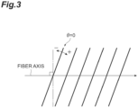
- the slant angle ⁇ 0 means the angle of the grating at which the return light is most suppressed, and corresponds to the angle of the grating of about 1° to 3° when the wave surface on which the light propagates is 0 degrees. Further, when the angle of the grating is increased, the return light increases again. Fig.
- Fig. 3 illustrates the grating with a plurality of lines at regular intervals.
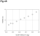
- Fig. 4A illustrates a relation between the slant angle ⁇ (deg) and the full width at half maximum ⁇ (FWHM (nm)).
- Fig. 4B when the slant angle ⁇ decreases, the reflection attenuation amount (dB) increases.
- Patent Document 3 a mode field diameter MFD1 in the SFG region is required to be equal to or greater than 15 ⁇ m, and a mode field diameter MFD3 in the other handling regions is required to be equal to or smaller than 12 ⁇ m, which is resistant to a bending loss.
- a mode field diameter MFD1 in the SFG region is required to be equal to or greater than 15 ⁇ m
- a mode field diameter MFD3 in the other handling regions is required to be equal to or smaller than 12 ⁇ m, which is resistant to a bending loss.
- Patent Document 3 a method in which an optical fiber containing GeO 2 in the core is prepared, and GeO 2 contained in the core is thermally diffused to form an MFD conversion portion in which the mode field diameter is gradually increased from MFD3 to MFD1 has been proposed.
- the concentration of GeO 2 which is a photosensitive material, in the MFD1 region is reduced.
- the threshold of GeO 2 concentration required for grating writing by ultraviolet light irradiation is equal to or greater than ⁇ 0.35% as a ratio of the amount of increase in the refractive index due to GeO 2 at the concentration to the refractive index of pure SiO 2 glass.
- an optical fiber with a guaranteed writing depth is prepared.
- the two optical fibers are fused and connected, and MFD conversion is performed by thermal diffusion or the like in a predetermined range including the fusional connection point.
- Patent Document 3 has a problem that a fusion loss occurs in addition to an increase in the unit price caused by an increase in the manufacturing process.
- FSG slanted fiber grating
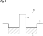
- Fig. 5 illustrates a refractive index profile along a radial direction of the optical fiber on which the slanted Bragg grating is formed.
- the slanted Bragg grating of the SFG in the present embodiment is formed as an optical fiber having the refractive index profile illustrated in Fig. 5 .
- An optical fiber 10 is an optical fiber comprised of silica-based glass.
- the optical fiber includes a core 11, a first cladding (optical cladding) 12 surrounding the core 11, and a second cladding (jacket) 13 surrounding the first cladding 12.
- the first cladding 12 has a refractive index lower than the refractive index of the core 11.
- the second cladding has a refractive index lower than the refractive index of the core 11 and higher than the refractive index of the first cladding 12.
- the boundary between the core 11 and the first cladding 12 is defined at a position at which the gradient of the refractive index is maximized.
- the boundary between the first cladding 12 and the second cladding 13 is defined at a position at which the gradient of the refractive index between the first cladding 12 and the second cladding 13 is maximized.
- the core 11 has a relative refractive index difference ⁇ n core at the center of the core.
- the first cladding 12 has a relative refractive index difference ⁇ n clad1 smaller than ⁇ n core .
- the second cladding 13 has a relative refractive index difference ⁇ n clad2 that is smaller than ⁇ n core and larger than ⁇ n clad1 .
- ⁇ n clad1 is a value taken by the approximate straight line of the refractive index profile in the first cladding 12 at the boundary between the core 11 and the first cladding 12.
- the approximate straight line of the refractive index profile in the first cladding 12 is a straight line connecting the refractive index at a position spaced outward by 1 ⁇ m along the radial direction from the boundary between the core 11 and the first cladding 12 with the refractive index at a position spaced by 1 ⁇ m toward the center of the core from the boundary between the second cladding 13 and the first cladding 12.
- the relative refractive index difference of each portion has a value based on the refractive index of pure SiO 2 glass.
- At least a portion of the first cladding 12 contains a photosensitive material that increases the refractive index by irradiation with light in a specific wavelength.
- the first cladding 12 may contain GeO 2 as the photosensitive material and may further contain B 2 O 3 as the photosensitive material.
- the core 11 and the second cladding 13 do not substantially contain the photosensitive material.
- the first cladding 12 and the second cladding 13 contain F.
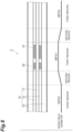
- Fig. 6 is a diagram illustrating a configuration of an SFG 1 in the present embodiment.
- a slanted Bragg grating 21 of the SFG 1 is formed on one optical fiber 10.
- the SFG 1 has a specific section divided into a first region, a second region, and a third region along the fiber axis direction.
- This specific section is a section having both ends that are defined along a fiber axis in the optical fiber 10.
- the first region is straight.
- a pair of second regions are provided on both sides of the first region, and a pair of third regions are further provided to sandwich the pair of second regions.
- the structure and the composition of the optical fiber 10 before ultraviolet light irradiation is uniform over the three regions.
- the slanted Bragg grating 21 having a slant angle ⁇ is formed in the first region.
- the mode field diameter MFD1 of the first region is larger than the mode field diameter MFD3 of the third region at the wavelength of 1.55 ⁇ m. It is preferable that the mode field diameter MFD3 of the third region is equal to or smaller than 11.5 ⁇ m at the wavelength of 1.55 ⁇ m. It is preferable that the mode field diameter MFD1 of the first region is equal to or greater than 12.0 ⁇ m at the wavelength of 1.55 ⁇ m. In the following description, all MFD1 and MFD3 are values at the wavelength of 1.55 ⁇ m.
- the mode field diameter in each of the pair of second regions gradually decreases from both ends of the first region toward each of the pair of third regions.
- the length of the first region defined along the fiber axis direction is from 10 mm to 100 mm, preferably from 20 mm to 80 mm.
- the mode field diameter of the optical fiber 10 before ultraviolet light irradiation is MFD3.
- the second region is irradiated with the ultraviolet light without passing through a phase mask.
- the irradiation amount of ultraviolet light along the fiber axis direction while performing irradiation with ultraviolet light, it is possible to gradually change the mode field diameter of the second region from MFD1 to MFD3 along the fiber axis direction.
- Fig. 7 is a diagram for explaining a method of forming the slanted Bragg grating.
- Light outputted from a light source 31 is reflected by a mirror 32. Then, the first region is irradiated with the reflected light with sequentially passing through a cylindrical lens 33 and a phase mask 34.
- the light outputted from the light source 31 has a wavelength capable of increasing the refractive index of the region containing the photosensitive material.
- a light incident direction to the mirror 32 is parallel to the fiber axis direction.
- a light emitting direction from the mirror 32 is perpendicular to the fiber axis direction.
- the cylindrical lens 33 converges the light arriving from the mirror 32 in the fiber axis direction.
- the phase mask 34 is a substantially flat transparent plate n which a groove having a periodic structure is formed on the main surface facing the first region.
- the +1st-order diffracted light and the -1st-order diffracted light outputted from the phase mask 34 interfere with each other, and a slanted Bragg grating is formed based on the interference fringes. Further, the slanted Bragg grating is formed over a predetermined range of the first region by integrally moving the mirror 32 and the cylindrical lens 33 along the fiber axis direction.
- the mode field diameter of the first region and the angle of the grating that realizes the zero slant angle have a correlation.
- the mode field diameter of the first region needs to be MFD1 ⁇ 1 corresponding to the desired grating angle ⁇ 1.
- the irradiation amount UV MFD- ⁇ 1 of the ultraviolet light required to obtain a mode field diameter MFD1 ⁇ 1 of the first region.
- the content of the photosensitive material in the optical fiber is not strictly uniform in the fiber axis direction, and the irradiation amount UV MFD- ⁇ 1 of the ultraviolet light required to obtain the mode field diameter MFD1 ⁇ 1 is different. Therefore, it is difficult to control the mode field diameter MFD1 ⁇ 1 with high accuracy.
- the configuration of the SFG 1 as illustrated in Fig. 8 is preferable.
- an MFD adjustment Bragg grating 22 is further formed in the first region in the configuration illustrated in Fig. 6 .
- the MFD adjustment Bragg grating 22 is prepared to monitor the mode field diameter of the first region during the production of a predetermined MFD1 of the SFG 1.
- the MFD adjustment Bragg grating 22 is formed at a position different from the position of the slanted Bragg grating 21 in the fiber axis direction.
- the MFD adjustment Bragg grating 22 may be formed on any side with respect to the slanted Bragg grating 21.
- the MFD adjustment Bragg grating 22 has an iso-refractive index surface perpendicular to the fiber axis.
- the iso-refractive index surface of the MFD adjustment Bragg grating 22 is parallel to the wave surface of the guided light.
- the MFD adjustment Bragg grating 22 Bragg-reflects light in a wavelength band different from the loss wavelength band of the slanted Bragg grating 21.
- a period ⁇ 1 of the iso-refractive index surface of the MFD adjustment Bragg grating 22 corresponds to the central wavelength ⁇ 1 of the wavelength band of the light reflected by Bragg.
- ⁇ 1 is preferably a wavelength band of 1.00 ⁇ m to 1.50 ⁇ m or a wavelength band of 1.65 ⁇ m to 1.70 ⁇ m in order to avoid the interference with such a wavelength band.
- the refractive index of the first cladding 12 increases from n clad1 before irradiation to n clad1+UV .
- the mode field diameter increases from MFD3 before irradiation to MFD1. Since only the first cladding 12 in the optical fiber 10 contains the photosensitive material, the MFD adjustment Bragg grating 22 is written to the first cladding 12 in the same manner as the slanted Bragg grating 21. An increase in MFD corresponds to light leaking into the first cladding 12 on which the MFD adjustment Bragg grating 22 is written.
- the predetermined MFD1 ⁇ 1 with high accuracy by monitoring the light quantity of the return light having a wavelength of ⁇ 1.
- the mode field diameter distribution in the second region along the fiber axis direction is realized by changing the irradiation amount of the ultraviolet light along the fiber axis direction. Specifically, the irradiation amount of the ultraviolet light required to realize MFD1 ⁇ 1 is adjusted at the boundary between the first region and the second region. The irradiation amount of the ultraviolet light is adjusted to 0 at the boundary between the third region and the second region. By adjusting the irradiation amount of the ultraviolet light while integrally moving the mirror 32 and the cylindrical lens 33 in the fiber axis direction, the desired mode field diameter distribution as described above can be obtained.
- the setting of the mode field diameter MFD1 in the first region and the formation of the slanted Bragg grating are performed in separate steps.
- the setting of the mode field diameter MFD1 in the first region and the formation of the slanted Bragg grating can be performed at the same time. This will be described below.
- the light intensity distribution in the interference fringes by the ⁇ 1st-order diffracted light outputted from the phase mask 34 has a bias and the degree of modulation depending on a distance between the optical fiber 10 and the phase mask 34.
- the longer this distance the larger the bias and the smaller the degree of modulation.
- the degree of modulation becomes 0, and the diffracted light generally observed in the far-field image is observed and becomes only the bias component.
- the distance between the optical fiber 10 and the phase mask 34 it is possible to increase the mode field diameter in accordance with the magnitude of the bias of the interference fringes, and it is possible to form the slanted Bragg grating 21 in accordance with the degree of modulation of the interference fringes.
- the larger the mode field diameter MFD1 of the first region, the smaller the angle of the grating that realizes the slant angle ⁇ 0 of the slanted Bragg grating 21 (angle formed by the optical propagation wave surface of the LP01 mode and the iso-refractive index surface of the grating).
- the full width at half maximum ⁇ of the fundamental spectrum decreases.
- the full width at half maximum ⁇ of the fundamental spectrum is equal to or smaller than 2.5 nm, preferably equal to or smaller than 2.0 nm, and the optimum is equal to or smaller than 1.5 nm.
- the governing factor of the grating writing ability is a ration of the type and content of the photosensitive material contained in at least a portion of the first cladding 12, to the leakage amount of guided light to the first cladding 12.
- Fig. 3 illustrates an example in which the entirety of the first cladding 12 contains the photosensitive material.
- the photosensitive material is preferably GeO 2 , and it is also preferable that GeO 2 and B 2 O 3 are co-doped. Further, it is also preferable that the first cladding 12 and the second cladding 13 contain F.
- the mode field diameter MFD3 of the third region is from 8 ⁇ m to 11.5 ⁇ m. Further, the mode field diameter MFD 1 of the first region is preferably from 12 ⁇ m to 22 ⁇ m.
- ultraviolet light (UV MFD1- ⁇ 1 ) for setting the mode field diameter of the first region to MFD 1 and ultraviolet light (UV grating ) for forming a grating are required.
- the relative refractive index difference increased by irradiation with ultraviolet light (UV MFD1- ⁇ 1 ) to set the mode field diameter to MFD1 is set as ⁇ n clad1+uv
- the relative refractive index difference increased by irradiation with ultraviolet light (UV grating ) to form the grating is set as ⁇ n grating
- the amount of increase in the refractive index of the formed grating is ⁇ n clad1+uv + ⁇ n grating .
- the GeO 2 content of the first cladding 12 when the GeO 2 content of the first cladding 12 is smaller than 0.35% as a ratio of the amount ⁇ n g of increase in the refractive index due to GeO 2 at the concentration to the refractive index of pure SiO 2 glass, it is difficult to form ⁇ n clad1+uv + ⁇ n grating . Therefore, the GeO 2 content of the first cladding 12 needs to be equal to or greater than 0.35%, preferably equal to or greater than 0.40%, and more preferably equal to or greater than 0.45%. Co-addition of B 2 O 3 and GeO 2 is also effective.
- the doping amount of B 2 O 3 is equal to or smaller than -0.20%, preferably equal to or smaller than -0.30%, and more preferably equal to or smaller than -0.40%, as a ratio of the amount ⁇ n g of increase in the refractive index due to GeO 2 at the concentration to the refractive index of pure SiO 2 glass.
- the doping amount of co-doped GeO 2 is equal to or greater than 0.35%, preferably equal to or greater than 0.40%, more preferably equal to or greater than 0.45%, as a ratio of the amount ⁇ n g of increase in the refractive index to the refractive index of pure SiO 2 glass.
- the ratio of the leakage amount of guided light to the first cladding 12 in a wavelength band of 1.55 ⁇ m is equal to or greater than 10% and smaller than 40%, preferably equal to or greater than 15% and smaller than 35%, and more preferably equal to or greater than 20% and smaller than 30%.
- the ratio of the leakage amount in the wavelength band of 1.55 ⁇ m is from 30% to 80%, preferably from 35% to 75%, and more preferably from 40% to 70%.
- a typical core 11 has a diameter of 7.5 ⁇ m ⁇ to 9.5 ⁇ m ⁇ .
- the relative refractive index difference ⁇ n of the core 11 is from 0.25 to 0.40%.
- the rising and falling cases may be linear or non-linear, or may be stepped. What is important is that the optical fiber structure may be designed in compliance with the ratio of the leakage amount of the guided light to the first cladding 12 described above.
- the ratio (r clad /r core ) of the radius r clad of the first cladding 12 to the radius r core of the core 11 is preferably from 3.0 to 4.0.
- SFG slanted fiber grating
- 10 optical fiber
- 11 ... core
- 12 first cladding (optical cladding)
- 13 ... second cladding (jacket)
- 21 ... slanted Bragg Grating
- 22 MFD adjustment Bragg grating
- 31 light source
- 32 mirror
- 33 cylindrical lens
- 34 ... phase mask.
Landscapes
- Physics & Mathematics (AREA)
- General Physics & Mathematics (AREA)
- Optics & Photonics (AREA)
- Optical Fibers, Optical Fiber Cores, And Optical Fiber Bundles (AREA)
- Diffracting Gratings Or Hologram Optical Elements (AREA)
Claims (7)
- Schrägfasergitter (1), umfassend:eine optische Faser (10), die aus Glas auf Siliziumdioxidbasis besteht, wobei die optische Faser (10) einschließteinen Kern (11), der sich entlang einer Faserachsenrichtung erstreckt,einen ersten Mantel (12), der den Kern (11) in einem Querschnitt senkrecht zu der Faserachsenrichtung umgibt, wobei der erste Mantel (12) mindestens einen Abschnitt aufweist, der ein lichtempfindliches Material aufweist und einen Brechungsindex aufweist, der niedriger ist als ein Brechungsindex des Kerns (11), wobei das lichtempfindliche Material den Brechungsindex des Abschnitts durch Bestrahlung mit Licht mit einer bestimmten Wellenlänge erhöht, undeinen zweiten Mantel (13), der den ersten Mantel (12) im Querschnitt umgibt, wobei der zweite Mantel (13) einen Brechungsindex aufweist, der niedriger als der Brechungsindex des Kerns (11) und höher als der Brechungsindex des ersten Mantels (12) ist,wobei ein bestimmter Abschnitt, der sich zwischen zwei verschiedenen Punkten befindet, die entlang der Faserachsenrichtung in der optischen Faser (10) angeordnet sind, konfiguriert ist miteinem ersten Bereich, der einen ersten Modenfelddurchmesser bei einer Wellenlänge von 1,55 µm aufweist und ein schräges Bragg-Gitter (21) mit einer zu dem Querschnitt geneigten Iso-Brechungsindex-Oberfläche einschließt, wobei das schräge Bragg-Gitter (21) in einem dem ersten Mantel (12) entsprechenden Bereich bereitgestellt ist,einem Paar zweiter Bereiche, die entlang der Faserachsenrichtung angeordnet sind, um den ersten Bereich sandwichartig zu umgeben, undeinem Paar dritter Bereiche, die entlang der Faserachsenrichtung angeordnet sind, um sowohl den ersten Bereich als auch das Paar zweiter Bereiche sandwichartig zu umgeben, wobei das Paar dritter Bereiche einen zweiten Modenfelddurchmesser aufweist, der kleiner ist als der erste Modenfelddurchmesser bei der Wellenlänge von 1,55 µm, dadurch gekennzeichnet, dass:eine Länge des ersten Bereichs, die entlang der Faserachsenrichtung definiert ist, von 10 mm bis 100 mm beträgt, undder erste Bereich ein MFD-Anpassungs-Bragg-Gitter (22) einschließt, das an einer Position angeordnet ist, die sich von dem schrägen Bragg-Gitter (21) entlang der Faserachsenrichtung unterscheidet, wobei das MFD-Anpassungs-Bragg-Gitter (22) eine Iso-Brechungsindex-Oberfläche senkrecht zu der Faserachsenrichtung aufweist und Licht in einem Wellenlängenband Bragg-reflektiert, das sich von einem Verlust-Wellenlängenband des schrägen Bragg-Gitters (21) unterscheidet.
- Schrägfasergitter (1) nach Anspruch 1, wobei
der erste Mantel (12) GeOz als das lichtempfindliche Material aufweist. - Schrägfasergitter (1) nach Anspruch 1 oder 2, wobei
der erste Mantel (12) weiter B2O3 als das lichtempfindliche Material aufweist. - Schrägfasergitter (1) nach einem der Ansprüche 1 bis 3, wobei
sowohl der erste Mantel (12) als auch der zweite Mantel (13) F aufweisen. - Schrägfasergitter (1) nach einem der Ansprüche 1 bis 4, wobei
der zweite Modenfelddurchmesser in jedem von dem Paar dritter Bereiche gleich oder kleiner als 11,5 µm ist. - Schrägfasergitter (1) nach einem der Ansprüche 1 bis 5, wobei
der erste Modenfelddurchmesser in dem ersten Bereich gleich oder größer als 12,0 µm ist. - Schrägfasergitter (1) nach einem der Ansprüche 1 bis 6, wobeider Modenfelddurchmesser bei der Wellenlänge von 1,55 µm in einem von dem Paar zweiter Bereiche allmählich entlang einer Richtung von einem Endabschnitt des ersten Bereichs zu einem von dem Paar dritter Bereiche hin abnimmt, undder Modenfelddurchmesser bei der Wellenlänge von 1,55 µm in dem anderen von dem Paar zweiter Bereiche allmählich entlang einer Richtung von dem anderen Endabschnitt des ersten Bereichs in Richtung des anderen von dem Paar dritter Bereiche abnimmt.
Applications Claiming Priority (2)
| Application Number | Priority Date | Filing Date | Title |
|---|---|---|---|
| JP2018202609 | 2018-10-29 | ||
| PCT/JP2019/040531 WO2020090450A1 (ja) | 2018-10-29 | 2019-10-15 | スラント型ファイバグレーティング |
Publications (3)
| Publication Number | Publication Date |
|---|---|
| EP3876003A1 EP3876003A1 (de) | 2021-09-08 |
| EP3876003A4 EP3876003A4 (de) | 2021-12-22 |
| EP3876003B1 true EP3876003B1 (de) | 2024-09-11 |
Family
ID=70462350
Family Applications (1)
| Application Number | Title | Priority Date | Filing Date |
|---|---|---|---|
| EP19880321.5A Active EP3876003B1 (de) | 2018-10-29 | 2019-10-15 | Schrägfasergitter |
Country Status (6)
| Country | Link |
|---|---|
| US (1) | US11448821B2 (de) |
| EP (1) | EP3876003B1 (de) |
| JP (1) | JP7347441B2 (de) |
| CN (1) | CN112840255B (de) |
| AU (1) | AU2019372515B2 (de) |
| WO (1) | WO2020090450A1 (de) |
Families Citing this family (1)
| Publication number | Priority date | Publication date | Assignee | Title |
|---|---|---|---|---|
| WO2026070620A1 (ja) * | 2024-09-30 | 2026-04-02 | 住友電気工業株式会社 | 利得等価フィルタ |
Family Cites Families (17)
| Publication number | Priority date | Publication date | Assignee | Title |
|---|---|---|---|---|
| JP3612780B2 (ja) * | 1995-04-14 | 2005-01-19 | 住友電気工業株式会社 | 光フィルタ |
| JP3497298B2 (ja) * | 1995-10-23 | 2004-02-16 | 株式会社フジクラ | 光ファイバフィルタ |
| JP3929495B2 (ja) * | 1996-01-18 | 2007-06-13 | ブリティッシュ・テレコミュニケーションズ・パブリック・リミテッド・カンパニー | 光感応性屈折率クラッドを備えた光導波路 |
| US6005999A (en) * | 1997-11-21 | 1999-12-21 | 3M Innovative Properties Company | Waveguide narrowband rejection filter |
| TW521165B (en) * | 2000-09-15 | 2003-02-21 | Ind Tech Res Inst | Method to reduce the transmission FWHM of slant type fiber grating |
| EP1267184B1 (de) | 2001-06-11 | 2004-12-08 | Avanex Corporation | Ein optischer Wellenleiter und Herstellungsverfahren für eine asymmetrische optische Filtervorrichtung |
| JP3754634B2 (ja) | 2001-06-27 | 2006-03-15 | 独立行政法人科学技術振興機構 | 光ファイバーグレーティングの作製方法及び作製装置、光ファイバーグレーティング |
| CA2396650C (en) * | 2001-08-31 | 2010-05-04 | Fujikura Ltd. | Fiber type optical component |
| JP4304416B2 (ja) | 2001-09-05 | 2009-07-29 | 住友電気工業株式会社 | 光ファイバフィルタおよびその製造方法 |
| JP2003202434A (ja) * | 2001-10-22 | 2003-07-18 | Fujikura Ltd | 光ファイバグレーティングの製造方法及び光ファイバグレーティング |
| EP1500959A4 (de) | 2002-04-30 | 2005-09-07 | Sumitomo Electric Industries | Optische faser und fasergitterfilter damit |
| TW200404172A (en) * | 2002-08-22 | 2004-03-16 | Showa Electric Wire & Cable Co | Pseudo slant fiber Bragg grating, multiple series fiber Bragg grating, optical fiber type coupler and optical connector |
| JP2004170476A (ja) | 2002-11-18 | 2004-06-17 | Showa Electric Wire & Cable Co Ltd | ファイバ・ブラッグ・グレーティングの形成方法 |
| US20160109650A1 (en) | 2014-10-16 | 2016-04-21 | Sumitomo Electric Industries, Ltd. | Optical fiber for fiber bragg grating |
| JP2016081032A (ja) * | 2014-10-16 | 2016-05-16 | 住友電気工業株式会社 | 光ファイバ |
| JP2018202609A (ja) | 2015-10-26 | 2018-12-27 | 綜研化学株式会社 | 撥水性部材及びその製造方法 |
| WO2017073670A1 (ja) * | 2015-10-27 | 2017-05-04 | 住友電気工業株式会社 | 光ファイバおよびそれを含むスラント型ファイバグレーティング |
-
2019
- 2019-10-15 EP EP19880321.5A patent/EP3876003B1/de active Active
- 2019-10-15 CN CN201980068039.8A patent/CN112840255B/zh active Active
- 2019-10-15 AU AU2019372515A patent/AU2019372515B2/en active Active
- 2019-10-15 JP JP2020553751A patent/JP7347441B2/ja active Active
- 2019-10-15 WO PCT/JP2019/040531 patent/WO2020090450A1/ja not_active Ceased
-
2021
- 2021-04-06 US US17/223,424 patent/US11448821B2/en active Active
Also Published As
| Publication number | Publication date |
|---|---|
| WO2020090450A1 (ja) | 2020-05-07 |
| JPWO2020090450A1 (ja) | 2021-09-16 |
| US11448821B2 (en) | 2022-09-20 |
| AU2019372515A1 (en) | 2021-05-06 |
| JP7347441B2 (ja) | 2023-09-20 |
| AU2019372515B2 (en) | 2024-08-29 |
| EP3876003A1 (de) | 2021-09-08 |
| US20210223468A1 (en) | 2021-07-22 |
| CN112840255A (zh) | 2021-05-25 |
| CN112840255B (zh) | 2022-11-25 |
| EP3876003A4 (de) | 2021-12-22 |
Similar Documents
| Publication | Publication Date | Title |
|---|---|---|
| EP1569020B1 (de) | Optisches Multiplexverfahren und optischer Multiplexer, und optischer Verstärker, der diese verwendet | |
| EP3457183B1 (de) | Mehradrige glasfaser, faser-bragg-gitter und verfahren zur herstellung eines faser-bragg-gitters | |
| US10908353B2 (en) | Optical fiber and slanted fiber grating | |
| JP2000266945A (ja) | 傾斜および線形チャープを有するフィルタ光導波路 | |
| US7203399B2 (en) | Optical fiber and fiber grating type filter including the same | |
| US6084996A (en) | Broadband long-period gratings | |
| US11448821B2 (en) | Slant-type fiber grating | |
| EP1333299B1 (de) | Optische Faser und geneigtes Fasergitter | |
| EP1219985A1 (de) | Verfahren zur herstellung optischen verlustfilters und optisches verlustfilter | |
| US6766080B2 (en) | Optical waveguide type defraction grating device and a method of manufacturing thereof | |
| US7035515B2 (en) | Optical waveguide and method for creating an asymmetrical optical filter device | |
| US12204140B2 (en) | Gain flattening filter, and method for manufacturing gain flattening filter | |
| US6915042B2 (en) | Slanted Bragg grating optical fiber and process for manufacturing such a fiber | |
| WO2017073670A1 (ja) | 光ファイバおよびそれを含むスラント型ファイバグレーティング | |
| JP2022100001A (ja) | 光ファイバ及び光ファイバフィルタ | |
| JP2003302547A (ja) | 光ファイバ、スラント型光ファイバグレーティング、帯域阻止光フィルタ、光増幅器用利得等化光フィルタおよび光増幅器モジュール | |
| JP2003222716A (ja) | 露光用マスク、光ファイバグレーティングの製造方法、光ファイバグレーティング及び光増幅器モジュール |
Legal Events
| Date | Code | Title | Description |
|---|---|---|---|
| STAA | Information on the status of an ep patent application or granted ep patent |
Free format text: STATUS: THE INTERNATIONAL PUBLICATION HAS BEEN MADE |
|
| PUAI | Public reference made under article 153(3) epc to a published international application that has entered the european phase |
Free format text: ORIGINAL CODE: 0009012 |
|
| STAA | Information on the status of an ep patent application or granted ep patent |
Free format text: STATUS: REQUEST FOR EXAMINATION WAS MADE |
|
| 17P | Request for examination filed |
Effective date: 20210413 |
|
| AK | Designated contracting states |
Kind code of ref document: A1 Designated state(s): AL AT BE BG CH CY CZ DE DK EE ES FI FR GB GR HR HU IE IS IT LI LT LU LV MC MK MT NL NO PL PT RO RS SE SI SK SM TR |
|
| A4 | Supplementary search report drawn up and despatched |
Effective date: 20211124 |
|
| RIC1 | Information provided on ipc code assigned before grant |
Ipc: G02B 6/036 20060101ALI20211118BHEP Ipc: G02B 6/02 20060101AFI20211118BHEP |
|
| DAV | Request for validation of the european patent (deleted) | ||
| DAX | Request for extension of the european patent (deleted) | ||
| GRAP | Despatch of communication of intention to grant a patent |
Free format text: ORIGINAL CODE: EPIDOSNIGR1 |
|
| STAA | Information on the status of an ep patent application or granted ep patent |
Free format text: STATUS: GRANT OF PATENT IS INTENDED |
|
| INTG | Intention to grant announced |
Effective date: 20240216 |
|
| GRAJ | Information related to disapproval of communication of intention to grant by the applicant or resumption of examination proceedings by the epo deleted |
Free format text: ORIGINAL CODE: EPIDOSDIGR1 |
|
| STAA | Information on the status of an ep patent application or granted ep patent |
Free format text: STATUS: REQUEST FOR EXAMINATION WAS MADE |
|
| GRAP | Despatch of communication of intention to grant a patent |
Free format text: ORIGINAL CODE: EPIDOSNIGR1 |
|
| STAA | Information on the status of an ep patent application or granted ep patent |
Free format text: STATUS: GRANT OF PATENT IS INTENDED |
|
| INTC | Intention to grant announced (deleted) | ||
| INTG | Intention to grant announced |
Effective date: 20240514 |
|
| P01 | Opt-out of the competence of the unified patent court (upc) registered |
Free format text: CASE NUMBER: APP_35000/2024 Effective date: 20240611 |
|
| GRAS | Grant fee paid |
Free format text: ORIGINAL CODE: EPIDOSNIGR3 |
|
| GRAA | (expected) grant |
Free format text: ORIGINAL CODE: 0009210 |
|
| STAA | Information on the status of an ep patent application or granted ep patent |
Free format text: STATUS: THE PATENT HAS BEEN GRANTED |
|
| AK | Designated contracting states |
Kind code of ref document: B1 Designated state(s): AL AT BE BG CH CY CZ DE DK EE ES FI FR GB GR HR HU IE IS IT LI LT LU LV MC MK MT NL NO PL PT RO RS SE SI SK SM TR |
|
| REG | Reference to a national code |
Ref country code: GB Ref legal event code: FG4D |
|
| REG | Reference to a national code |
Ref country code: CH Ref legal event code: EP |
|
| REG | Reference to a national code |
Ref country code: DE Ref legal event code: R096 Ref document number: 602019058898 Country of ref document: DE |
|
| REG | Reference to a national code |
Ref country code: IE Ref legal event code: FG4D |
|
| REG | Reference to a national code |
Ref country code: LT Ref legal event code: MG9D |
|
| PG25 | Lapsed in a contracting state [announced via postgrant information from national office to epo] |
Ref country code: NO Free format text: LAPSE BECAUSE OF FAILURE TO SUBMIT A TRANSLATION OF THE DESCRIPTION OR TO PAY THE FEE WITHIN THE PRESCRIBED TIME-LIMIT Effective date: 20241211 |
|
| REG | Reference to a national code |
Ref country code: NL Ref legal event code: MP Effective date: 20240911 |
|
| PG25 | Lapsed in a contracting state [announced via postgrant information from national office to epo] |
Ref country code: GR Free format text: LAPSE BECAUSE OF FAILURE TO SUBMIT A TRANSLATION OF THE DESCRIPTION OR TO PAY THE FEE WITHIN THE PRESCRIBED TIME-LIMIT Effective date: 20241212 Ref country code: FI Free format text: LAPSE BECAUSE OF FAILURE TO SUBMIT A TRANSLATION OF THE DESCRIPTION OR TO PAY THE FEE WITHIN THE PRESCRIBED TIME-LIMIT Effective date: 20240911 |
|
| PG25 | Lapsed in a contracting state [announced via postgrant information from national office to epo] |
Ref country code: BG Free format text: LAPSE BECAUSE OF FAILURE TO SUBMIT A TRANSLATION OF THE DESCRIPTION OR TO PAY THE FEE WITHIN THE PRESCRIBED TIME-LIMIT Effective date: 20240911 |
|
| PG25 | Lapsed in a contracting state [announced via postgrant information from national office to epo] |
Ref country code: LV Free format text: LAPSE BECAUSE OF FAILURE TO SUBMIT A TRANSLATION OF THE DESCRIPTION OR TO PAY THE FEE WITHIN THE PRESCRIBED TIME-LIMIT Effective date: 20240911 |
|
| PG25 | Lapsed in a contracting state [announced via postgrant information from national office to epo] |
Ref country code: HR Free format text: LAPSE BECAUSE OF FAILURE TO SUBMIT A TRANSLATION OF THE DESCRIPTION OR TO PAY THE FEE WITHIN THE PRESCRIBED TIME-LIMIT Effective date: 20240911 |
|
| PG25 | Lapsed in a contracting state [announced via postgrant information from national office to epo] |
Ref country code: RS Free format text: LAPSE BECAUSE OF FAILURE TO SUBMIT A TRANSLATION OF THE DESCRIPTION OR TO PAY THE FEE WITHIN THE PRESCRIBED TIME-LIMIT Effective date: 20241211 Ref country code: ES Free format text: LAPSE BECAUSE OF FAILURE TO SUBMIT A TRANSLATION OF THE DESCRIPTION OR TO PAY THE FEE WITHIN THE PRESCRIBED TIME-LIMIT Effective date: 20240911 |
|
| PG25 | Lapsed in a contracting state [announced via postgrant information from national office to epo] |
Ref country code: RS Free format text: LAPSE BECAUSE OF FAILURE TO SUBMIT A TRANSLATION OF THE DESCRIPTION OR TO PAY THE FEE WITHIN THE PRESCRIBED TIME-LIMIT Effective date: 20241211 Ref country code: NO Free format text: LAPSE BECAUSE OF FAILURE TO SUBMIT A TRANSLATION OF THE DESCRIPTION OR TO PAY THE FEE WITHIN THE PRESCRIBED TIME-LIMIT Effective date: 20241211 Ref country code: LV Free format text: LAPSE BECAUSE OF FAILURE TO SUBMIT A TRANSLATION OF THE DESCRIPTION OR TO PAY THE FEE WITHIN THE PRESCRIBED TIME-LIMIT Effective date: 20240911 Ref country code: HR Free format text: LAPSE BECAUSE OF FAILURE TO SUBMIT A TRANSLATION OF THE DESCRIPTION OR TO PAY THE FEE WITHIN THE PRESCRIBED TIME-LIMIT Effective date: 20240911 Ref country code: GR Free format text: LAPSE BECAUSE OF FAILURE TO SUBMIT A TRANSLATION OF THE DESCRIPTION OR TO PAY THE FEE WITHIN THE PRESCRIBED TIME-LIMIT Effective date: 20241212 Ref country code: FI Free format text: LAPSE BECAUSE OF FAILURE TO SUBMIT A TRANSLATION OF THE DESCRIPTION OR TO PAY THE FEE WITHIN THE PRESCRIBED TIME-LIMIT Effective date: 20240911 Ref country code: ES Free format text: LAPSE BECAUSE OF FAILURE TO SUBMIT A TRANSLATION OF THE DESCRIPTION OR TO PAY THE FEE WITHIN THE PRESCRIBED TIME-LIMIT Effective date: 20240911 Ref country code: BG Free format text: LAPSE BECAUSE OF FAILURE TO SUBMIT A TRANSLATION OF THE DESCRIPTION OR TO PAY THE FEE WITHIN THE PRESCRIBED TIME-LIMIT Effective date: 20240911 |
|
| REG | Reference to a national code |
Ref country code: AT Ref legal event code: MK05 Ref document number: 1723191 Country of ref document: AT Kind code of ref document: T Effective date: 20240911 |
|
| PG25 | Lapsed in a contracting state [announced via postgrant information from national office to epo] |
Ref country code: NL Free format text: LAPSE BECAUSE OF FAILURE TO SUBMIT A TRANSLATION OF THE DESCRIPTION OR TO PAY THE FEE WITHIN THE PRESCRIBED TIME-LIMIT Effective date: 20240911 |
|
| PG25 | Lapsed in a contracting state [announced via postgrant information from national office to epo] |
Ref country code: PT Free format text: LAPSE BECAUSE OF FAILURE TO SUBMIT A TRANSLATION OF THE DESCRIPTION OR TO PAY THE FEE WITHIN THE PRESCRIBED TIME-LIMIT Effective date: 20250113 Ref country code: IS Free format text: LAPSE BECAUSE OF FAILURE TO SUBMIT A TRANSLATION OF THE DESCRIPTION OR TO PAY THE FEE WITHIN THE PRESCRIBED TIME-LIMIT Effective date: 20250111 |
|
| PG25 | Lapsed in a contracting state [announced via postgrant information from national office to epo] |
Ref country code: RO Free format text: LAPSE BECAUSE OF FAILURE TO SUBMIT A TRANSLATION OF THE DESCRIPTION OR TO PAY THE FEE WITHIN THE PRESCRIBED TIME-LIMIT Effective date: 20240911 Ref country code: SM Free format text: LAPSE BECAUSE OF FAILURE TO SUBMIT A TRANSLATION OF THE DESCRIPTION OR TO PAY THE FEE WITHIN THE PRESCRIBED TIME-LIMIT Effective date: 20240911 |
|
| PG25 | Lapsed in a contracting state [announced via postgrant information from national office to epo] |
Ref country code: EE Free format text: LAPSE BECAUSE OF FAILURE TO SUBMIT A TRANSLATION OF THE DESCRIPTION OR TO PAY THE FEE WITHIN THE PRESCRIBED TIME-LIMIT Effective date: 20240911 Ref country code: AT Free format text: LAPSE BECAUSE OF FAILURE TO SUBMIT A TRANSLATION OF THE DESCRIPTION OR TO PAY THE FEE WITHIN THE PRESCRIBED TIME-LIMIT Effective date: 20240911 |
|
| PG25 | Lapsed in a contracting state [announced via postgrant information from national office to epo] |
Ref country code: CZ Free format text: LAPSE BECAUSE OF FAILURE TO SUBMIT A TRANSLATION OF THE DESCRIPTION OR TO PAY THE FEE WITHIN THE PRESCRIBED TIME-LIMIT Effective date: 20240911 Ref country code: PL Free format text: LAPSE BECAUSE OF FAILURE TO SUBMIT A TRANSLATION OF THE DESCRIPTION OR TO PAY THE FEE WITHIN THE PRESCRIBED TIME-LIMIT Effective date: 20240911 |
|
| PG25 | Lapsed in a contracting state [announced via postgrant information from national office to epo] |
Ref country code: IT Free format text: LAPSE BECAUSE OF FAILURE TO SUBMIT A TRANSLATION OF THE DESCRIPTION OR TO PAY THE FEE WITHIN THE PRESCRIBED TIME-LIMIT Effective date: 20240911 Ref country code: SK Free format text: LAPSE BECAUSE OF FAILURE TO SUBMIT A TRANSLATION OF THE DESCRIPTION OR TO PAY THE FEE WITHIN THE PRESCRIBED TIME-LIMIT Effective date: 20240911 |
|
| REG | Reference to a national code |
Ref country code: DE Ref legal event code: R119 Ref document number: 602019058898 Country of ref document: DE |
|
| REG | Reference to a national code |
Ref country code: CH Ref legal event code: PL |
|
| PG25 | Lapsed in a contracting state [announced via postgrant information from national office to epo] |
Ref country code: MC Free format text: LAPSE BECAUSE OF FAILURE TO SUBMIT A TRANSLATION OF THE DESCRIPTION OR TO PAY THE FEE WITHIN THE PRESCRIBED TIME-LIMIT Effective date: 20240911 |
|
| PG25 | Lapsed in a contracting state [announced via postgrant information from national office to epo] |
Ref country code: DE Free format text: LAPSE BECAUSE OF NON-PAYMENT OF DUE FEES Effective date: 20250501 |
|
| PG25 | Lapsed in a contracting state [announced via postgrant information from national office to epo] |
Ref country code: DK Free format text: LAPSE BECAUSE OF FAILURE TO SUBMIT A TRANSLATION OF THE DESCRIPTION OR TO PAY THE FEE WITHIN THE PRESCRIBED TIME-LIMIT Effective date: 20240911 |
|
| PG25 | Lapsed in a contracting state [announced via postgrant information from national office to epo] |
Ref country code: LU Free format text: LAPSE BECAUSE OF NON-PAYMENT OF DUE FEES Effective date: 20241015 Ref country code: BE Free format text: LAPSE BECAUSE OF NON-PAYMENT OF DUE FEES Effective date: 20241031 |
|
| PLBE | No opposition filed within time limit |
Free format text: ORIGINAL CODE: 0009261 |
|
| STAA | Information on the status of an ep patent application or granted ep patent |
Free format text: STATUS: NO OPPOSITION FILED WITHIN TIME LIMIT |
|
| PG25 | Lapsed in a contracting state [announced via postgrant information from national office to epo] |
Ref country code: CH Free format text: LAPSE BECAUSE OF NON-PAYMENT OF DUE FEES Effective date: 20241031 |
|
| REG | Reference to a national code |
Ref country code: BE Ref legal event code: MM Effective date: 20241031 |
|
| 26N | No opposition filed |
Effective date: 20250612 |
|
| PG25 | Lapsed in a contracting state [announced via postgrant information from national office to epo] |
Ref country code: SE Free format text: LAPSE BECAUSE OF FAILURE TO SUBMIT A TRANSLATION OF THE DESCRIPTION OR TO PAY THE FEE WITHIN THE PRESCRIBED TIME-LIMIT Effective date: 20240911 |
|
| PGFP | Annual fee paid to national office [announced via postgrant information from national office to epo] |
Ref country code: GB Payment date: 20250828 Year of fee payment: 7 |
|
| PGFP | Annual fee paid to national office [announced via postgrant information from national office to epo] |
Ref country code: FR Payment date: 20250908 Year of fee payment: 7 |
|
| PG25 | Lapsed in a contracting state [announced via postgrant information from national office to epo] |
Ref country code: IE Free format text: LAPSE BECAUSE OF NON-PAYMENT OF DUE FEES Effective date: 20241015 |
|
| PG25 | Lapsed in a contracting state [announced via postgrant information from national office to epo] |
Ref country code: CY Free format text: LAPSE BECAUSE OF FAILURE TO SUBMIT A TRANSLATION OF THE DESCRIPTION OR TO PAY THE FEE WITHIN THE PRESCRIBED TIME-LIMIT; INVALID AB INITIO Effective date: 20191015 |
|
| PG25 | Lapsed in a contracting state [announced via postgrant information from national office to epo] |
Ref country code: HU Free format text: LAPSE BECAUSE OF FAILURE TO SUBMIT A TRANSLATION OF THE DESCRIPTION OR TO PAY THE FEE WITHIN THE PRESCRIBED TIME-LIMIT; INVALID AB INITIO Effective date: 20191015 |