EP3875121B1 - Gasverarbeitungsvorrichtung - Google Patents
Gasverarbeitungsvorrichtung Download PDFInfo
- Publication number
- EP3875121B1 EP3875121B1 EP19880633.3A EP19880633A EP3875121B1 EP 3875121 B1 EP3875121 B1 EP 3875121B1 EP 19880633 A EP19880633 A EP 19880633A EP 3875121 B1 EP3875121 B1 EP 3875121B1
- Authority
- EP
- European Patent Office
- Prior art keywords
- power supply
- processing device
- electrode
- discharge lamp
- gas
- Prior art date
- Legal status (The legal status is an assumption and is not a legal conclusion. Google has not performed a legal analysis and makes no representation as to the accuracy of the status listed.)
- Active
Links
Images



Classifications
-
- B—PERFORMING OPERATIONS; TRANSPORTING
- B01—PHYSICAL OR CHEMICAL PROCESSES OR APPARATUS IN GENERAL
- B01J—CHEMICAL OR PHYSICAL PROCESSES, e.g. CATALYSIS OR COLLOID CHEMISTRY; THEIR RELEVANT APPARATUS
- B01J19/00—Chemical, physical or physico-chemical processes in general; Their relevant apparatus
- B01J19/08—Processes employing the direct application of electric or wave energy, or particle radiation; Apparatus therefor
- B01J19/12—Processes employing the direct application of electric or wave energy, or particle radiation; Apparatus therefor employing electromagnetic waves
- B01J19/122—Incoherent waves
- B01J19/123—Ultraviolet light
-
- C—CHEMISTRY; METALLURGY
- C01—INORGANIC CHEMISTRY
- C01B—NON-METALLIC ELEMENTS; COMPOUNDS THEREOF; METALLOIDS OR COMPOUNDS THEREOF NOT COVERED BY SUBCLASS C01C
- C01B13/00—Oxygen; Ozone; Oxides or hydroxides in general
- C01B13/10—Preparation of ozone
-
- A—HUMAN NECESSITIES
- A61—MEDICAL OR VETERINARY SCIENCE; HYGIENE
- A61L—METHODS OR APPARATUS FOR STERILISING MATERIALS OR OBJECTS IN GENERAL; DISINFECTION, STERILISATION OR DEODORISATION OF AIR; CHEMICAL ASPECTS OF BANDAGES, DRESSINGS, ABSORBENT PADS OR SURGICAL ARTICLES; MATERIALS FOR BANDAGES, DRESSINGS, ABSORBENT PADS OR SURGICAL ARTICLES
- A61L9/00—Disinfection, sterilisation or deodorisation of air
- A61L9/015—Disinfection, sterilisation or deodorisation of air using gaseous or vaporous substances, e.g. ozone
-
- B—PERFORMING OPERATIONS; TRANSPORTING
- B01—PHYSICAL OR CHEMICAL PROCESSES OR APPARATUS IN GENERAL
- B01D—SEPARATION
- B01D53/00—Separation of gases or vapours; Recovering vapours of volatile solvents from gases; Chemical or biological purification of waste gases, e.g. engine exhaust gases, smoke, fumes, flue gases, aerosols
- B01D53/007—Separation of gases or vapours; Recovering vapours of volatile solvents from gases; Chemical or biological purification of waste gases, e.g. engine exhaust gases, smoke, fumes, flue gases, aerosols by irradiation
-
- B—PERFORMING OPERATIONS; TRANSPORTING
- B01—PHYSICAL OR CHEMICAL PROCESSES OR APPARATUS IN GENERAL
- B01J—CHEMICAL OR PHYSICAL PROCESSES, e.g. CATALYSIS OR COLLOID CHEMISTRY; THEIR RELEVANT APPARATUS
- B01J19/00—Chemical, physical or physico-chemical processes in general; Their relevant apparatus
- B01J19/0006—Controlling or regulating processes
- B01J19/0013—Controlling the temperature of the process
-
- A—HUMAN NECESSITIES
- A61—MEDICAL OR VETERINARY SCIENCE; HYGIENE
- A61L—METHODS OR APPARATUS FOR STERILISING MATERIALS OR OBJECTS IN GENERAL; DISINFECTION, STERILISATION OR DEODORISATION OF AIR; CHEMICAL ASPECTS OF BANDAGES, DRESSINGS, ABSORBENT PADS OR SURGICAL ARTICLES; MATERIALS FOR BANDAGES, DRESSINGS, ABSORBENT PADS OR SURGICAL ARTICLES
- A61L2209/00—Aspects relating to disinfection, sterilisation or deodorisation of air
- A61L2209/20—Method-related aspects
- A61L2209/21—Use of chemical compounds for treating air or the like
- A61L2209/212—Use of ozone, e.g. generated by UV radiation or electrical discharge
-
- A—HUMAN NECESSITIES
- A61—MEDICAL OR VETERINARY SCIENCE; HYGIENE
- A61L—METHODS OR APPARATUS FOR STERILISING MATERIALS OR OBJECTS IN GENERAL; DISINFECTION, STERILISATION OR DEODORISATION OF AIR; CHEMICAL ASPECTS OF BANDAGES, DRESSINGS, ABSORBENT PADS OR SURGICAL ARTICLES; MATERIALS FOR BANDAGES, DRESSINGS, ABSORBENT PADS OR SURGICAL ARTICLES
- A61L9/00—Disinfection, sterilisation or deodorisation of air
- A61L9/16—Disinfection, sterilisation or deodorisation of air using physical phenomena
- A61L9/18—Radiation
- A61L9/20—Ultraviolet radiation
-
- B—PERFORMING OPERATIONS; TRANSPORTING
- B01—PHYSICAL OR CHEMICAL PROCESSES OR APPARATUS IN GENERAL
- B01D—SEPARATION
- B01D2251/00—Reactants
- B01D2251/10—Oxidants
- B01D2251/104—Ozone
-
- B—PERFORMING OPERATIONS; TRANSPORTING
- B01—PHYSICAL OR CHEMICAL PROCESSES OR APPARATUS IN GENERAL
- B01D—SEPARATION
- B01D2259/00—Type of treatment
- B01D2259/80—Employing electric, magnetic, electromagnetic or wave energy, or particle radiation
- B01D2259/804—UV light
-
- B—PERFORMING OPERATIONS; TRANSPORTING
- B01—PHYSICAL OR CHEMICAL PROCESSES OR APPARATUS IN GENERAL
- B01J—CHEMICAL OR PHYSICAL PROCESSES, e.g. CATALYSIS OR COLLOID CHEMISTRY; THEIR RELEVANT APPARATUS
- B01J2219/00—Chemical, physical or physico-chemical processes in general; Their relevant apparatus
- B01J2219/08—Processes employing the direct application of electric or wave energy, or particle radiation; Apparatus therefor
- B01J2219/0869—Feeding or evacuating the reactor
-
- B—PERFORMING OPERATIONS; TRANSPORTING
- B01—PHYSICAL OR CHEMICAL PROCESSES OR APPARATUS IN GENERAL
- B01J—CHEMICAL OR PHYSICAL PROCESSES, e.g. CATALYSIS OR COLLOID CHEMISTRY; THEIR RELEVANT APPARATUS
- B01J2219/00—Chemical, physical or physico-chemical processes in general; Their relevant apparatus
- B01J2219/08—Processes employing the direct application of electric or wave energy, or particle radiation; Apparatus therefor
- B01J2219/0871—Heating or cooling of the reactor
-
- B—PERFORMING OPERATIONS; TRANSPORTING
- B01—PHYSICAL OR CHEMICAL PROCESSES OR APPARATUS IN GENERAL
- B01J—CHEMICAL OR PHYSICAL PROCESSES, e.g. CATALYSIS OR COLLOID CHEMISTRY; THEIR RELEVANT APPARATUS
- B01J2219/00—Chemical, physical or physico-chemical processes in general; Their relevant apparatus
- B01J2219/08—Processes employing the direct application of electric or wave energy, or particle radiation; Apparatus therefor
- B01J2219/0873—Materials to be treated
- B01J2219/0875—Gas
-
- B—PERFORMING OPERATIONS; TRANSPORTING
- B01—PHYSICAL OR CHEMICAL PROCESSES OR APPARATUS IN GENERAL
- B01J—CHEMICAL OR PHYSICAL PROCESSES, e.g. CATALYSIS OR COLLOID CHEMISTRY; THEIR RELEVANT APPARATUS
- B01J2219/00—Chemical, physical or physico-chemical processes in general; Their relevant apparatus
- B01J2219/08—Processes employing the direct application of electric or wave energy, or particle radiation; Apparatus therefor
- B01J2219/12—Processes employing electromagnetic waves
- B01J2219/1203—Incoherent waves
-
- C—CHEMISTRY; METALLURGY
- C01—INORGANIC CHEMISTRY
- C01B—NON-METALLIC ELEMENTS; COMPOUNDS THEREOF; METALLOIDS OR COMPOUNDS THEREOF NOT COVERED BY SUBCLASS C01C
- C01B2201/00—Preparation of ozone by electrical discharge
- C01B2201/60—Feed streams for electrical dischargers
- C01B2201/64—Oxygen
-
- C—CHEMISTRY; METALLURGY
- C01—INORGANIC CHEMISTRY
- C01B—NON-METALLIC ELEMENTS; COMPOUNDS THEREOF; METALLOIDS OR COMPOUNDS THEREOF NOT COVERED BY SUBCLASS C01C
- C01B2201/00—Preparation of ozone by electrical discharge
- C01B2201/80—Additional processes occurring alongside the electrical discharges, e.g. catalytic processes
- C01B2201/82—Treatment with ultraviolet light
-
- H—ELECTRICITY
- H01—ELECTRIC ELEMENTS
- H01J—ELECTRIC DISCHARGE TUBES OR DISCHARGE LAMPS
- H01J65/00—Lamps without any electrode inside the vessel; Lamps with at least one main electrode outside the vessel
- H01J65/04—Lamps in which a gas filling is excited to luminesce by an external electromagnetic field or by external corpuscular radiation, e.g. for indicating plasma display panels
- H01J65/042—Lamps in which a gas filling is excited to luminesce by an external electromagnetic field or by external corpuscular radiation, e.g. for indicating plasma display panels by an external electromagnetic field
- H01J65/046—Lamps in which a gas filling is excited to luminesce by an external electromagnetic field or by external corpuscular radiation, e.g. for indicating plasma display panels by an external electromagnetic field the field being produced by using capacitive means around the vessel
Definitions
- the present invention relates to a gas processing device, and especially relates to a gas processing device that performs gas processing with ozone generated by irradiating oxygen in a gas with ultraviolet rays.
- a gas containing a predetermined concentration of ozone has sterilizing and deodorizing activities, and is used in various fields.
- a photochemical reaction using an ultraviolet ray source is known.
- Patent Document 1 discloses a configuration in which solenoid valves are arranged on an air intake port and an air exhaust port of a tube body in which a discharge lamp is accommodated, and the valves are controlled to be opened and closed according to a concentration of ozone in order to prevent the ozone from leaking out.
- WO 2018/030144 A1 and JP 2001 342139 A describe ozone generators wherein a discharge lamp and a power supply unit are arranged in different communicating chambers within the same housing.
- Patent Document 1 JP-A-2011-101748
- Ozone generated by irradiating oxygen contained in a processing target gas with ultraviolet rays is consumed by reaction with a substance contained in the processing target gas.
- a part of ozone that has not reacted with the substance contained in the processing target gas comes into contact with parts in a gas processing device, and deterioration and damage of the parts progress.
- Patent Document 1 As in Patent Document 1 described above, a configuration that prevents the parts and the like from being exposed to a high concentration of ozone by accommodating the discharge lamp in a dedicated casing, isolating a space in which ozone is generated, and controlling the ozone concentration inside and outside the casing is considered.
- a power supply line electrically connected to the discharge lamp cannot be separated from the discharge lamp, a part thereof is exposed to the high concentration of ozone, and progress of deterioration and damage thereof is unavoidable.
- an object of the present invention is to provide a gas processing device in which acceleration of deterioration in power supply line is suppressed by a configuration in which the power supply line is not exposed to ozone generated by ultraviolet rays emitted from a discharge lamp.
- a gas processing device according to the present invention is described in claim 1.
- the gas processing device of the present invention is connected to an exhaust duct and the like, takes in the processing target gas that flows from the air intake port, and while allowing the processing target gas to flow toward the air exhaust port, allows the processing target gas to come into contact with ozone generated by the ultraviolet rays emitted from the discharge lamp to perform processing.
- the ozone is generated when oxygen contained in the processing target gas is irradiated with the ultraviolet rays emitted from the discharge lamp.
- reaction expressed by following equations (1) and (2) progresses and the ozone is generated.
- O( 1 D) represents an oxygen atom in an excited state that exhibits high reactivity.
- O( 3 P) represents an oxygen atom in a ground state.
- hv represents that the ultraviolet rays are absorbed.
- O( 3 P) generated by equation (1) reacts with oxygen (O 2 ) contained in the processing target gas to generate ozone (O 3 ) according to equation (2).
- the first opening region is an opening region for guiding the processing target gas from outside the gas processing device to the hollow portion.
- the discharge lamp is accommodated in the hollow portion, and the processing target gas guided to the hollow portion is processed by the ozone generated by irradiation of the ultraviolet rays from the discharge lamp.
- the second opening region is an opening region for guiding the gas processed by the gas processing device out of the processing target gas.
- an end on which the first opening region is arranged is the first end, and an end on which the second opening region is arranged is the second end.
- the hollow portion is a region where the ozone is brought into contact with the processing target gas taken into the same from the first opening region to process. That is, the processing target gas is taken into the gas processing device from the first opening region, passes through the hollow portion, and is discharged to the outside of the gas processing device from the second opening region.
- An entire portion including the first opening region, the hollow portion, and the second opening region through which the processing target gas flows is the main body portion.
- the discharge lamp is provided with the first electrode and the second electrode to which the voltage is applied.
- the first electrode and the second electrode are electrically connected to the power supply unit arranged outside the casing via the power supply lines (first power supply line and second power supply line), respectively, and when the voltage is applied from the power supply unit to between the first electrode and the second electrode, the discharge lamp emits the ultraviolet rays.
- the gas processing device of the present invention is configured such that both the first power supply line connecting the first electrode of the discharge lamp to the power supply unit and the second power supply line connecting the second electrode to the power supply unit pass through the first end side on which the first opening region for taking in the processing target gas from outside the gas processing device into the gas processing device is arranged.
- the processing target gas flowing through the main body portion is taken into the first opening region, goes to the hollow portion, and is discharged from the second opening region. That is, while the processing target gas is taken into the gas processing device, an air flow is constantly generated in the hollow portion from the first end side to the second end side. Therefore, most of the ozone which is generated in the hollow portion and does not react with the processing target gas goes toward not the first end but the second end to be discharged from the second opening region.
- the first power supply line and the second power supply line are not exposed to the ozone generated in the hollow portion, and progress of deterioration and damage of the first power supply line and the second power supply line is suppressed.
- the processing target gas also contains not a little moisture.
- the moisture in the processing target gas is irradiated with the ultraviolet rays emitted by the discharge lamp, the reactions expressed by equation (1) above and equation (3) below progress, and hydroxyl radical ( ⁇ OH) is also generated.
- Radical products such as hydroxyl radical are also highly reactive like ozone, and promote deterioration and damage of parts and the like.
- almost all of the radical products generated in the hollow portion go toward not the first end but the second end to be discharged from the second opening region. That is, it is possible to suppress the progress of deterioration and damage of the first power supply line and the second power supply line due to the radical products.
- the first opening region may be formed to be narrower toward the second opening region.
- the processing target gas that flows is guided to the hollow portion while being compressed in the first opening region.
- the processing target gas that travels to the hollow portion while being compressed has a higher pressure in the travel direction and a flow velocity increases. Therefore, the gas in the hollow portion is pushed out to the second end side with a stronger pressure, and the ozone and radical products generated in the hollow portion are less likely to go to the first end, so that a risk of exposure of the first power supply line and the second power supply line to the ozone and radical products is further reduced.
- the casing may be provided with a support member that supports the discharge lamp in which a groove in which the first power supply line and the second power supply line may be internally provided is formed on the first end side.
- the first power supply line and the second power supply line are internally provided in the support member, so that they are protected from direct contact with the ozone.
- a high voltage is applied between the first electrode and the second electrode at the time of light emission, and a high voltage difference is generated between the first power supply line and the second power supply line.
- a material of coating of each power supply line and the like there is a possibility that current leakage occurs only when the power supply lines come into contact with each other. Therefore, it is possible to suppress the current leakage by forming the groove in which each power supply line may be independently internally provided in the support member.
- a groove that may accommodate the power supply lines together may be formed.
- the discharge lamp may be formed such that the first electrode and the second electrode are opposed to each other across the tube body on an outer wall surface of the tube body, and arranged such that a direction in which the first electrode and the second electrode are opposed to each other and a direction in which the power supply unit is arranged with respect to the discharge lamp are not parallel to each other as seen in the first direction.
- the discharge lamp may be an excimer lamp filled with a discharge gas containing Xe.
- the excimer lamp is characterized in that this is a lamp that emits ultraviolet rays for generating ozone, and that this may obtain a stable output immediately after being turned on, so that this may be restarted without standby time even when this is turned off when it is not needed.
- the lamp when the processing target gas does not flow, the lamp may be turned off so that the ozone and radical products are not generated.
- the standby time is required at the time of restart, the ozone generated during that time might flow to the first end side and come into contact with the first and second power supply lines; however, the excimer lamp does not require the standby time.
- each power supply line may be protected from exposure to the ozone and radical products.
- the gas processing device is provided with
- the gas processing device is provided with the power supply box in which the power supply unit is accommodated, and the power supply box may be arranged such that one flat surface of the power supply box is in contact with the flat surface formed on the side surface of the casing, so that the gas processing device in which the casing and the power supply box are integrated may be formed.
- the power supply box may be arranged such that one flat surface of the power supply box is in contact with the flat surface formed on the side surface of the casing, so that the gas processing device in which the casing and the power supply box are integrated may be formed.
- shapes of the contact surfaces of the power supply box and the casing are the same such that they have a rectangular parallelepiped shape as a whole, it becomes easy to stack or align in a case where a plurality of same gas processing devices are arranged so as to conform to the number of ducts, and a flexible arrangement configuration may be taken.
- the power supply box is provided with a cooling air intake port, a cooling air exhaust port, and a cooling fan, and it is configured such that outside air different from the processing target gas, taken into the power supply box from the cooling air intake port by operation of the cooling fan is discharged from the cooling air exhaust port after cooling the power supply unit.
- the power supply unit is cooled by the outside air instead of the processing target gas.
- a clean state of a part of the power supply unit and the power supply line arranged in the power supply box may be maintained as compared with a case where this is continuously exposed to the processing target gas and the processed gas, and progress of deterioration and damage is suppressed.
- a gas processing device is realized in which a power supply line is not exposed to ozone generated by ultraviolet rays emitted from a discharge lamp and acceleration of deterioration of the power supply line is suppressed.
- FIG. 1 is a schematic entire perspective view of an embodiment of a gas processing device.
- a gas processing device 1 in this embodiment is obtained by stacking a casing 10 through which a processing target gas flows and a power supply box 16 in which a power supply unit 15 is accommodated and has a rectangular parallelepiped shape as a whole. Structures of the casing 10 and the power supply box 16 are described later in detail.
- Fig. 2 is a schematic cross-sectional view of the gas processing device 1 illustrated in Fig. 1 as seen from the side.
- the casing 10 is provided with a main body portion 12 including a hollow portion 12b, and a first end 12d and a second end 12e located on both ends of the main body portion 12.
- the first end 12d is provided with a first opening region 12a communicated with the hollow portion 12b.
- the second end 12e is provided with a second opening region 12c communicated with the hollow portion 12b in a position on a side opposite to the first opening region 12a.
- a discharge lamp 11 is arranged inside the hollow portion 12b along a tube axis of the main body portion 12.
- the power supply unit 15 is arranged in the power supply box 16.
- the discharge lamp 11 to which a voltage is applied from the power supply unit 15 emits ultraviolet rays L1.
- a processing target gas G1 is taken in from outside the gas processing device 1 through the first opening region 12a, this is guided to the hollow portion 12b.
- the processing target gas G1 that flows through the hollow portion 12b reacts with ozone and radical products generated by irradiation of the ultraviolet rays L1 from the discharge lamp 11, and a substance contained in the processing target gas G1 (processing target substance) is processed.
- a processed gas G2 obtained after processing in this manner is discharged out of the gas processing device 1 from the second opening region 12c side.
- a structure of the discharge lamp 11 is described later.
- the gas processing device 1 illustrated in Fig. 2 is provided with support members 13 for supporting the discharge lamp 11 arranged in the hollow portion 12b in positions of the first end 12d and the second end 12e.
- Both the first opening region 12a and the second opening region 12c are formed to be narrower toward the hollow portion 12b. Because the first opening region 12a becomes narrower toward the second opening region 12c, a pressure in a travel direction of the processing target gas G1 flowing through the hollow portion 12b increases, and a flow velocity of the processing target gas G1 increases. Therefore, an effect of pushing the ozone generated by the ultraviolet rays L1 emitted from the discharge lamp 11 toward the second opening region 12c is enhanced.
- opening diameters of the first opening region 12a and the second opening region 12c on the first end 12d and the second end 12e, respectively, are preferably made the same as a diameter of the air conditioning duct, and in most cases, the opening diameter is made about 15 cm.
- the hollow portion 12b is configured such that a gap between an outer wall surface of a tube body 21 forming the discharge lamp 11 and an inner wall surface in a site of the hollow portion 12b of the casing 10 is as narrow as possible such that the processing target gas G1 is brought into contact with the ozone.
- the gap is preferably about 1 cm.
- the discharge lamp 11 arranged in the hollow portion 12b is formed with a diameter or a width of the tube body 21 of about 3 cm to 5 cm, and an opening diameter of the hollow portion 12b of the casing 10 is made about 4 cm to 6 cm.
- the power supply unit 15 is accommodated in the dedicated power supply box 16.
- the power supply box 16 is arranged so as to come into contact with a flat surface forming an outer wall surface of the casing 10. Furthermore, the power supply box 16 is provided with a cooling air intake port 17a for taking in cooling air W1 for cooling the power supply unit 15, a cooling air exhaust port 17b for discharging the cooling air W1, and a cooling fan 18 for blowing the cooling air W1.
- the cooling fan 18 is arranged at the cooling air exhaust port 17b, but this may also be arranged at the cooling air intake port 17a.
- the power supply unit 15 accommodated in the power supply box 16 is cooled by outside air taken in through the cooling air intake port 17a, the power supply unit 15 may maintain a cleaner state for a long period of time than a case where this is cooled by the processing target gas G1 or the processed gas G2.
- the discharge lamp 11 and the power supply unit 15 are electrically connected to each other with a first power supply line 14a and a second power supply line 14b.
- a voltage is applied from the power supply unit 15 to between the first power supply line 14a and the second power supply line 14b, the ultraviolet rays L1 are emitted from the discharge lamp 11.
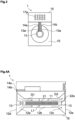
- FIG. 3 is a front view of the gas processing device 1 in Fig. 1 as seen from the first end 12d side in a tube axis direction of the discharge lamp 11.
- two grooves 13a are formed in the support member 13, and the power supply lines (14a and 14b) are independently internally provided therein.
- both the lines may be separated by a certain distance or more.
- an effect of suppressing a leakage current generated between the power supply lines (14a and 14b) may also be obtained even in a case where a high voltage is applied when the discharge lamp 11 is lit.
- the leakage current is generated only when both the lines come into contact with each other, although it depends on a material and a thickness of a coating of each of the power supply lines (14a and 14b). Therefore, it is preferable to wire both the power supply lines (14a and 14b) so as to be separated from each other, and a separation distance may be secured by wiring them by using the grooves 13a as described above.
- a cavity may be formed inside the support member 13, and the power supply lines (14a and 14b) may be wired therein.
- the discharge lamp 11 is formed of a cylindrical first electrode 22a extending along the tube axis in the cylindrical tube body 21 and a second electrode 22b that covers the outer wall surface of the tube body 21 in a mesh pattern, and the tube body 21 is filled with a discharging gas containing Xe.
- the first electrode 22a and the second electrode 22b are electrically connected to the first power supply line 14a and the second power supply line 14b, respectively, on the first end 12d side.
- the discharge lamp 11 may also be the discharge lamp 11 having a so-called double tube structure.
- the discharge lamp 11 having the double tube structure is the discharge lamp 11 having a double cylindrical structure in which one electrode 22a is arranged on an inner wall surface of an inner tube, and the other electrode 22b is arranged on an outer wall surface of an outer tube.
- the discharge lamp 11 may be the discharge lamp 11 having a so-called flat tube structure.
- the discharge lamp 11 having the flat tube structure is described with reference to Figs. 4A , 4B , and 4C .
- Fig. 4A is a schematic cross-sectional view of the gas processing device 1 by the discharge lamp 11 having the flat tube structure as seen from the side.
- Fig. 4B is a schematic cross-sectional view of the gas processing device 1 by the discharge lamp 11 having the flat tube structure as seen from above. As illustrated in Fig.
- the discharge lamp 11 having the flat tube structure is the discharge lamp 11 including the tube body 21 having a rectangular tube shape in which the electrode 22a is provided on one outer wall of a pair of outer walls facing each other of the tube body 21 and the electrode 22b is provided on the other outer wall, so that both the electrodes (22a and 22b) are provided so as to be separated from each other.
- both the electrodes (22a and 22b) of the discharge lamp 11 having the flat tube structure are formed into a mesh shape.
- Fig. 4C is a schematic cross-sectional view of the gas processing device 1 by the discharge lamp 11 having the flat tube structure as seen from the front.
- the discharge lamp 11 having the flat tube structure is arranged such that an opposing direction 41a of the first electrode 22a and the second electrode 22b is orthogonal to an arranging direction 41b of the power supply unit 15 with respect to the discharge lamp 11 as seen in the tube axis direction of the tube body 21.
- the power supply lines (14a and 14b) are wired so as to be separated from each other, a twist of the first power supply line 14a and the second power supply line 14b is less likely to occur, the power supply lines (14a and 14b) hardly come into contact with each other, and current leakage between the power supply lines (14a and 14b) may be suppressed.
- the discharge lamp 11 is an excimer lamp filled with the discharging gas containing Xe
- the structure illustrated in Figs. 2 to 4C is merely an example and a shape is not limited to this.
- the ultraviolet rays L1 preferably have a short wavelength, and specifically, the lamp preferably may emit the ultraviolet rays L1 having a wavelength of 200 nm or shorter.
- the discharge lamp 11 and the power supply unit 15 are connected to each other by the power supply lines (14a and 14b). Inside the discharge lamp 11, the power supply line 14a is electrically connected to the electrode 22a on the first opening region 12a side, and outside the discharge lamp 11, the power supply line 14b is electrically connected to the electrode 22b on the first opening region 12a side.
- the voltage output from the power supply unit 15 is applied to the electrodes (22a and 22b) through the power supply lines (14a and 14b), respectively, the discharge lamp 11 emits light, and the ultraviolet rays L1 are emitted to the processing target gas G1.
- Coating materials of the power supply lines (14a and 14b) include polyvinyl chloride, polyethylene, and Teflon (registered trademark).
- Polyvinyl chloride and polyethylene have very low resistance to ozone and radical products, and when exposed to a high concentration of ozone and radical products, they deteriorate in a short period of time.
- Teflon registered trademark
- the ozone and radical products are constantly generated while the processing target gas G1 flows and the discharge lamp 11 emits the ultraviolet rays L1. Then, the ozone and radical products generated in the hollow portion 12b are swept downstream toward the second opening region 12c by the processing target gas G1 flowing from the upstream.
- the first power supply line 14a and the second power supply line 14b are wired on the first opening region 12a side located upstream of the hollow portion 12b and are not exposed to the ozone and radical products generated in the hollow portion 12b, so that the progress of deterioration and damage by the ozone and radical products is suppressed.
- the main body portion 12 may have the same opening diameter from the first end 12d to the second end 12e. It does not matter if the power supply lines (14a and 14b) may not be internally provided in the grooves 13a formed in the support member 13.
- Figs. 1 and 2 Although a case where one surface of the power supply box 16 is arranged so as to be in contact with the surface of the casing 10 is illustrated in Figs. 1 and 2 , they may also be arranged in separate positions.
- the discharge lamp 11 having the flat tube structure is arranged such that the opposing direction 41a of the first electrode 22a and the second electrode 22b is orthogonal to the arranging direction 41b of the power supply unit 15 with respect to the discharge lamp 11 as seen in the tube axis direction of the tube body 21.
- an angle formed by the opposing direction 41a and the arranging direction 41b is at least not parallel to each other, and this is preferably 60° or larger and 120° or smaller, and more preferably 70° or larger and 110° or smaller.
- the angle formed by the opposing direction 41a and the arranging direction 41b is within this angle range, it becomes easy to wire the power supply lines (14a and 14b) so as not to be easily twisted with the separation distance (insulation distance) kept, and the current leakage between the power supply lines (14a and 14b) may be suppressed. From the viewpoint of device design, it is desirable to arrange the power supply unit 15 in this manner.
Landscapes
- Health & Medical Sciences (AREA)
- Chemical & Material Sciences (AREA)
- General Health & Medical Sciences (AREA)
- Organic Chemistry (AREA)
- Public Health (AREA)
- Animal Behavior & Ethology (AREA)
- Veterinary Medicine (AREA)
- Chemical Kinetics & Catalysis (AREA)
- Life Sciences & Earth Sciences (AREA)
- Epidemiology (AREA)
- Toxicology (AREA)
- Physics & Mathematics (AREA)
- Electromagnetism (AREA)
- Oil, Petroleum & Natural Gas (AREA)
- Inorganic Chemistry (AREA)
- General Chemical & Material Sciences (AREA)
- Analytical Chemistry (AREA)
- Engineering & Computer Science (AREA)
- Disinfection, Sterilisation Or Deodorisation Of Air (AREA)
- Oxygen, Ozone, And Oxides In General (AREA)
- Physical Or Chemical Processes And Apparatus (AREA)
- Crystals, And After-Treatments Of Crystals (AREA)
- Incineration Of Waste (AREA)
- Treating Waste Gases (AREA)
Claims (6)
- Gasverarbeitungsvorrichtung (1), die ein Sauerstoff enthaltendes Verarbeitungszielgas (G1), das aus einer Lufteinlassöffnung eingelassen wird, mit ultravioletten Strahlen (11) bestrahlt und dann das Gas aus einer Luftauslassöffnung auslässt, die in einer von einer Position der Lufteinlassöffnung verschiedenen Position vorgesehen ist, wobei die Gasverarbeitungsvorrichtung umfasst:ein Gehäuse (10), umfassend ein erstes Ende (12d), das einen ersten Öffnungsbereich (12a) aufweist, der die Lufteinlassöffnung bildet, ein zweites Ende (12e), das in einer von dem ersten Ende (12d) in einer ersten Richtung getrennten Position angeordnet ist, wobei das zweite Ende (12e) einen zweiten Öffnungsbereich (12c) aufweist, der die Luftauslassöffnung bildet, und einen Hauptkörperabschnitt (12) mit einem hohlen Abschnitt (12b) darin, wobei der hohle Abschnitt den ersten Öffnungsbereich (12a) und den zweiten Öffnungsbereich (12c) miteinander verbindet,eine Entladungslampe (11), die in dem hohlen Abschnitt (12b) angeordnet ist und einen Röhrenkörper (21) aufweist mit einer sich in der ersten Richtung erstreckenden Form, einer ersten Elektrode (22a) und einer zweiten Elektrode (22b), wobei die Entladungslampe (11) die ultravioletten Strahlen (L1) aus dem Röhrenkörper (21) durch Anlegen einer Spannung zwischen der ersten Elektrode (22a) und der zweiten Elektrode (22b) emittiert,eine erste Stromversorgungsleitung (14a), die so verdrahtet ist, dass sie durch eine Seite verläuft, die dem ersten Ende (12d) näher ist als dem Hauptkörperabschnitt (12), wobei die erste Stromversorgungsleitung (14a) die Stromversorgungseinheit (15) mit der ersten Elektrode (22a) verbindet, undeine zweite Stromversorgungsleitung (14b), die so verdrahtet ist, dass sie durch die Seite verläuft, die dem ersten Ende (12d) näher ist als dem Hauptkörperabschnitt (12), wobei die zweite Stromversorgungsleitung (14b) die Stromversorgungseinheit (15) elektrisch mit der zweiten Elektrode (22b) verbindet,und dadurch gekennzeichnet, dass,
die Gasaufbereitungsvorrichtung (1) auch eine Stromversorgungseinheit (15) umfasst, die in einem Stromversorgungskasten (16) untergebracht ist, das außerhalb des Gehäuses (10) angeordnet ist, und wobei der Stromversorgungskasten (16) mit einer Kühlluft-Einlassöffnung (17a), einer Kühlluft-Auslassöffnung (17b) und einem Kühlgebläse (18) versehen ist, und wobei die Gasaufbereitungsvorrichtung (1) so konfiguriert ist, dass Außenluft, die von dem Verarbeitungszielgas (G1) verschieden ist, die durch den Betrieb des Kühlgebläses (18) von der Kühlluft-Einlassöffnung (17a) in den Stromversorgungskasten (16) eingelassen worden ist, aus der Kühlluft-Auslassöffnung (17b) nach dem Kühlen der Stromversorgungseinheit (15) abgelassen wird. - Gasaufbereitungsvorrichtung (1) nach Anspruch 1, wobei
der erste Öffnungsbereich (12a) so geformt ist, dass er in Richtung auf den zweiten Öffnungsbereich (12c) verengt ist. - Gasaufbereitungsvorrichtung (1) nach Anspruch 1 oder 2, wobei
das Gehäuse (10) mit einem die Entladungslampe (11) tragenden Trägerelement (13) versehen ist, in dem eine Nut, in der die erste Stromversorgungsleitung (14a) und die zweite Stromversorgungsleitung (14b) innenliegend vorgesehen sind, auf einer Seite des ersten Endes (12d) gebildet ist. - Gasaufbereitungsvorrichtung (1) nach einem der Ansprüche 1 bis 3, wobei
die Entladungslampe (11) so geformt ist, dass die erste Elektrode (22a) und die zweite Elektrode (22b) einander über den Röhrenkörper (21) hinweg an einer Außenwandfläche des Röhrenkörpers (21) gegenüberliegen und so angeordnet sind, dass eine Richtung, in der die erste Elektrode (22a) und die zweite Elektrode (22b) einander gegenüberliegen, und eine Richtung, in der die Stromversorgungseinheit (15) in Bezug auf die Entladungslampe (11) angeordnet ist, nicht parallel zueinander sind, wenn in der ersten Richtung betrachtet. - Gasaufbereitungsvorrichtung (1) nach einem der Ansprüche 1 bis 4, wobei
die Entladungslampe (11) eine Excimer-Lampe ist, die mit einem Xe-haltigen Entladungsgas gefüllt ist. - Gasbearbeitungsvorrichtung (1) nach einem der Ansprüche 1 bis 5, wobei
der Stromversorgungskasten (16) so angeordnet ist, dass eine flache Oberfläche des Stromversorgungskastens (16) in Kontakt mit einer flachen Oberfläche steht, die an einer Seitenfläche des Gehäuses (10) gebildet ist.
Applications Claiming Priority (2)
| Application Number | Priority Date | Filing Date | Title |
|---|---|---|---|
| JP2018204299A JP7206810B2 (ja) | 2018-10-30 | 2018-10-30 | 気体処理装置 |
| PCT/JP2019/035659 WO2020090238A1 (ja) | 2018-10-30 | 2019-09-11 | 気体処理装置 |
Publications (4)
| Publication Number | Publication Date |
|---|---|
| EP3875121A1 EP3875121A1 (de) | 2021-09-08 |
| EP3875121A4 EP3875121A4 (de) | 2021-12-29 |
| EP3875121B1 true EP3875121B1 (de) | 2023-10-04 |
| EP3875121C0 EP3875121C0 (de) | 2023-10-04 |
Family
ID=70463940
Family Applications (1)
| Application Number | Title | Priority Date | Filing Date |
|---|---|---|---|
| EP19880633.3A Active EP3875121B1 (de) | 2018-10-30 | 2019-09-11 | Gasverarbeitungsvorrichtung |
Country Status (6)
| Country | Link |
|---|---|
| US (1) | US11325095B2 (de) |
| EP (1) | EP3875121B1 (de) |
| JP (1) | JP7206810B2 (de) |
| CN (1) | CN112770788B (de) |
| TW (1) | TWI789545B (de) |
| WO (1) | WO2020090238A1 (de) |
Families Citing this family (2)
| Publication number | Priority date | Publication date | Assignee | Title |
|---|---|---|---|---|
| TWI823320B (zh) * | 2022-03-31 | 2023-11-21 | 群邁通訊股份有限公司 | 氣體淨化設備及方法 |
| CN116928785A (zh) * | 2022-03-31 | 2023-10-24 | 群迈通讯股份有限公司 | 气体净化设备及方法 |
Citations (1)
| Publication number | Priority date | Publication date | Assignee | Title |
|---|---|---|---|---|
| EP3943124A1 (de) * | 2019-05-21 | 2022-01-26 | Ushio Denki Kabushiki Kaisha | Gasbehandlungsvorrichtung und gasbehandlungsverfahren |
Family Cites Families (19)
| Publication number | Priority date | Publication date | Assignee | Title |
|---|---|---|---|---|
| US4273660A (en) * | 1979-02-21 | 1981-06-16 | Beitzel Stuart W | Purification of water through the use of ozone and ultraviolet light |
| US5505912A (en) * | 1992-02-18 | 1996-04-09 | Cryptonics Corporation | Lamp cooling for a UV lamp reactor assembly |
| JP3046951B2 (ja) * | 1998-04-27 | 2000-05-29 | 株式会社セイスイ | 空気清浄化装置 |
| JP2001342139A (ja) | 2000-06-02 | 2001-12-11 | Takei Hiromi | 花粉症予防及び症状緩和システム |
| CN2768788Y (zh) * | 2004-12-30 | 2006-04-05 | 上海国达特殊光源有限公司 | 管状紫外线空气清洁器 |
| JP4394096B2 (ja) | 2006-07-24 | 2010-01-06 | 浩一 新井 | 放電灯 |
| JP2008036168A (ja) | 2006-08-07 | 2008-02-21 | Toshiba Corp | 脱臭装置 |
| JP4788534B2 (ja) | 2006-09-07 | 2011-10-05 | ウシオ電機株式会社 | エキシマランプ |
| JP2011101748A (ja) | 2009-11-11 | 2011-05-26 | Stanley Electric Co Ltd | 紫外線ランプを用いた殺菌・脱臭装置 |
| JP2012000216A (ja) | 2010-06-16 | 2012-01-05 | Isuzu Motors Ltd | 紫外線殺菌装置 |
| JP2013103184A (ja) * | 2011-11-15 | 2013-05-30 | Nec Lighting Ltd | 浄化装置 |
| JP2013118072A (ja) | 2011-12-02 | 2013-06-13 | Ushio Inc | 紫外線放電ランプ |
| CN103959431B (zh) * | 2011-12-02 | 2016-06-29 | 优志旺电机株式会社 | 准分子灯 |
| US20140221692A1 (en) | 2013-02-04 | 2014-08-07 | Chevron Phillips Chemical Company Lp | Flow Reactor Vessels and Reactor Systems |
| CN104689362B (zh) * | 2015-03-23 | 2018-02-23 | 佛山柯维光电股份有限公司 | 一种多功能消毒灭菌器及其使用方法 |
| JP6778003B2 (ja) * | 2016-03-24 | 2020-10-28 | 株式会社オーク製作所 | オゾン生成装置及びオゾン処理装置 |
| JP6288568B2 (ja) | 2016-08-09 | 2018-03-07 | ウシオ電機株式会社 | オゾン発生装置 |
| WO2019131124A1 (ja) | 2017-12-27 | 2019-07-04 | ウシオ電機株式会社 | 気体処理装置 |
| JP7287103B2 (ja) * | 2019-05-14 | 2023-06-06 | ウシオ電機株式会社 | 紫外線照射装置、及びこれを備えた気体処理装置 |
-
2018
- 2018-10-30 JP JP2018204299A patent/JP7206810B2/ja active Active
-
2019
- 2019-09-03 TW TW108131595A patent/TWI789545B/zh active
- 2019-09-11 EP EP19880633.3A patent/EP3875121B1/de active Active
- 2019-09-11 WO PCT/JP2019/035659 patent/WO2020090238A1/ja not_active Ceased
- 2019-09-11 US US17/283,225 patent/US11325095B2/en active Active
- 2019-09-11 CN CN201980062274.4A patent/CN112770788B/zh active Active
Patent Citations (1)
| Publication number | Priority date | Publication date | Assignee | Title |
|---|---|---|---|---|
| EP3943124A1 (de) * | 2019-05-21 | 2022-01-26 | Ushio Denki Kabushiki Kaisha | Gasbehandlungsvorrichtung und gasbehandlungsverfahren |
Also Published As
| Publication number | Publication date |
|---|---|
| JP2020068995A (ja) | 2020-05-07 |
| EP3875121A1 (de) | 2021-09-08 |
| WO2020090238A1 (ja) | 2020-05-07 |
| EP3875121A4 (de) | 2021-12-29 |
| US11325095B2 (en) | 2022-05-10 |
| TW202033226A (zh) | 2020-09-16 |
| JP7206810B2 (ja) | 2023-01-18 |
| US20210346861A1 (en) | 2021-11-11 |
| TWI789545B (zh) | 2023-01-11 |
| CN112770788B (zh) | 2022-03-18 |
| EP3875121C0 (de) | 2023-10-04 |
| CN112770788A (zh) | 2021-05-07 |
Similar Documents
| Publication | Publication Date | Title |
|---|---|---|
| JP7232428B2 (ja) | 気体処理装置 | |
| US10207926B2 (en) | Ozone generator | |
| US20100239473A1 (en) | Apparatus for decomposing organic matter with radical treatment method using electric discharge | |
| WO2015121633A1 (en) | Air decontamination device & method | |
| US11325095B2 (en) | Gas processing device | |
| CN109562937B (zh) | 臭氧发生装置 | |
| JP7145597B2 (ja) | オゾン生成装置およびエキシマランプ点灯方法 | |
| CN100429123C (zh) | 电子束辐射装置和方法 | |
| EP3346808A1 (de) | Planare vorrichtung und verfahren zur erzeugung eines plasmas oder reaktiver spezies | |
| CN209917565U (zh) | 气体处理装置 | |
| KR102262447B1 (ko) | 플라즈마를 이용한 식품 살균 장치 | |
| JP6694595B2 (ja) | オゾン発生装置 | |
| WO2020262478A1 (ja) | 気体処理方法、気体処理装置 | |
| WO2019082703A1 (ja) | 光脱臭装置および光脱臭方法 | |
| JP7086653B2 (ja) | 水処理装置 | |
| US12042575B2 (en) | Non-contact microplasma ozonized mist radical sterilizer | |
| CN118160781A (zh) | 一种物料消杀装置 | |
| KR20250007614A (ko) | 유체의 이온화를 위한 방법 및 디바이스 | |
| JP2021133941A (ja) | 保管容器 |
Legal Events
| Date | Code | Title | Description |
|---|---|---|---|
| STAA | Information on the status of an ep patent application or granted ep patent |
Free format text: STATUS: THE INTERNATIONAL PUBLICATION HAS BEEN MADE |
|
| PUAI | Public reference made under article 153(3) epc to a published international application that has entered the european phase |
Free format text: ORIGINAL CODE: 0009012 |
|
| STAA | Information on the status of an ep patent application or granted ep patent |
Free format text: STATUS: REQUEST FOR EXAMINATION WAS MADE |
|
| 17P | Request for examination filed |
Effective date: 20210409 |
|
| AK | Designated contracting states |
Kind code of ref document: A1 Designated state(s): AL AT BE BG CH CY CZ DE DK EE ES FI FR GB GR HR HU IE IS IT LI LT LU LV MC MK MT NL NO PL PT RO RS SE SI SK SM TR |
|
| A4 | Supplementary search report drawn up and despatched |
Effective date: 20211129 |
|
| RIC1 | Information provided on ipc code assigned before grant |
Ipc: C01B 13/11 20060101ALI20211123BHEP Ipc: H01J 61/52 20060101ALI20211123BHEP Ipc: H01J 65/00 20060101ALI20211123BHEP Ipc: A61L 9/015 20060101ALI20211123BHEP Ipc: A61L 9/20 20060101AFI20211123BHEP |
|
| DAV | Request for validation of the european patent (deleted) | ||
| DAX | Request for extension of the european patent (deleted) | ||
| STAA | Information on the status of an ep patent application or granted ep patent |
Free format text: STATUS: EXAMINATION IS IN PROGRESS |
|
| 17Q | First examination report despatched |
Effective date: 20220926 |
|
| GRAP | Despatch of communication of intention to grant a patent |
Free format text: ORIGINAL CODE: EPIDOSNIGR1 |
|
| STAA | Information on the status of an ep patent application or granted ep patent |
Free format text: STATUS: GRANT OF PATENT IS INTENDED |
|
| INTG | Intention to grant announced |
Effective date: 20230420 |
|
| GRAS | Grant fee paid |
Free format text: ORIGINAL CODE: EPIDOSNIGR3 |
|
| GRAA | (expected) grant |
Free format text: ORIGINAL CODE: 0009210 |
|
| STAA | Information on the status of an ep patent application or granted ep patent |
Free format text: STATUS: THE PATENT HAS BEEN GRANTED |
|
| AK | Designated contracting states |
Kind code of ref document: B1 Designated state(s): AL AT BE BG CH CY CZ DE DK EE ES FI FR GB GR HR HU IE IS IT LI LT LU LV MC MK MT NL NO PL PT RO RS SE SI SK SM TR |
|
| REG | Reference to a national code |
Ref country code: GB Ref legal event code: FG4D |
|
| REG | Reference to a national code |
Ref country code: CH Ref legal event code: EP |
|
| REG | Reference to a national code |
Ref country code: DE Ref legal event code: R096 Ref document number: 602019038884 Country of ref document: DE |
|
| REG | Reference to a national code |
Ref country code: IE Ref legal event code: FG4D |
|
| U01 | Request for unitary effect filed |
Effective date: 20231023 |
|
| U07 | Unitary effect registered |
Designated state(s): AT BE BG DE DK EE FI FR IT LT LU LV MT NL PT SE SI Effective date: 20231027 |
|
| PG25 | Lapsed in a contracting state [announced via postgrant information from national office to epo] |
Ref country code: GR Free format text: LAPSE BECAUSE OF FAILURE TO SUBMIT A TRANSLATION OF THE DESCRIPTION OR TO PAY THE FEE WITHIN THE PRESCRIBED TIME-LIMIT Effective date: 20240105 |
|
| PG25 | Lapsed in a contracting state [announced via postgrant information from national office to epo] |
Ref country code: IS Free format text: LAPSE BECAUSE OF FAILURE TO SUBMIT A TRANSLATION OF THE DESCRIPTION OR TO PAY THE FEE WITHIN THE PRESCRIBED TIME-LIMIT Effective date: 20240204 |
|
| PG25 | Lapsed in a contracting state [announced via postgrant information from national office to epo] |
Ref country code: ES Free format text: LAPSE BECAUSE OF FAILURE TO SUBMIT A TRANSLATION OF THE DESCRIPTION OR TO PAY THE FEE WITHIN THE PRESCRIBED TIME-LIMIT Effective date: 20231004 |
|
| PG25 | Lapsed in a contracting state [announced via postgrant information from national office to epo] |
Ref country code: IS Free format text: LAPSE BECAUSE OF FAILURE TO SUBMIT A TRANSLATION OF THE DESCRIPTION OR TO PAY THE FEE WITHIN THE PRESCRIBED TIME-LIMIT Effective date: 20240204 Ref country code: GR Free format text: LAPSE BECAUSE OF FAILURE TO SUBMIT A TRANSLATION OF THE DESCRIPTION OR TO PAY THE FEE WITHIN THE PRESCRIBED TIME-LIMIT Effective date: 20240105 Ref country code: ES Free format text: LAPSE BECAUSE OF FAILURE TO SUBMIT A TRANSLATION OF THE DESCRIPTION OR TO PAY THE FEE WITHIN THE PRESCRIBED TIME-LIMIT Effective date: 20231004 |
|
| PG25 | Lapsed in a contracting state [announced via postgrant information from national office to epo] |
Ref country code: RS Free format text: LAPSE BECAUSE OF FAILURE TO SUBMIT A TRANSLATION OF THE DESCRIPTION OR TO PAY THE FEE WITHIN THE PRESCRIBED TIME-LIMIT Effective date: 20231004 Ref country code: PL Free format text: LAPSE BECAUSE OF FAILURE TO SUBMIT A TRANSLATION OF THE DESCRIPTION OR TO PAY THE FEE WITHIN THE PRESCRIBED TIME-LIMIT Effective date: 20231004 Ref country code: NO Free format text: LAPSE BECAUSE OF FAILURE TO SUBMIT A TRANSLATION OF THE DESCRIPTION OR TO PAY THE FEE WITHIN THE PRESCRIBED TIME-LIMIT Effective date: 20240104 Ref country code: HR Free format text: LAPSE BECAUSE OF FAILURE TO SUBMIT A TRANSLATION OF THE DESCRIPTION OR TO PAY THE FEE WITHIN THE PRESCRIBED TIME-LIMIT Effective date: 20231004 |
|
| REG | Reference to a national code |
Ref country code: DE Ref legal event code: R097 Ref document number: 602019038884 Country of ref document: DE |
|
| PG25 | Lapsed in a contracting state [announced via postgrant information from national office to epo] |
Ref country code: CZ Free format text: LAPSE BECAUSE OF FAILURE TO SUBMIT A TRANSLATION OF THE DESCRIPTION OR TO PAY THE FEE WITHIN THE PRESCRIBED TIME-LIMIT Effective date: 20231004 |
|
| PG25 | Lapsed in a contracting state [announced via postgrant information from national office to epo] |
Ref country code: SK Free format text: LAPSE BECAUSE OF FAILURE TO SUBMIT A TRANSLATION OF THE DESCRIPTION OR TO PAY THE FEE WITHIN THE PRESCRIBED TIME-LIMIT Effective date: 20231004 |
|
| PG25 | Lapsed in a contracting state [announced via postgrant information from national office to epo] |
Ref country code: SM Free format text: LAPSE BECAUSE OF FAILURE TO SUBMIT A TRANSLATION OF THE DESCRIPTION OR TO PAY THE FEE WITHIN THE PRESCRIBED TIME-LIMIT Effective date: 20231004 Ref country code: SK Free format text: LAPSE BECAUSE OF FAILURE TO SUBMIT A TRANSLATION OF THE DESCRIPTION OR TO PAY THE FEE WITHIN THE PRESCRIBED TIME-LIMIT Effective date: 20231004 Ref country code: RO Free format text: LAPSE BECAUSE OF FAILURE TO SUBMIT A TRANSLATION OF THE DESCRIPTION OR TO PAY THE FEE WITHIN THE PRESCRIBED TIME-LIMIT Effective date: 20231004 Ref country code: CZ Free format text: LAPSE BECAUSE OF FAILURE TO SUBMIT A TRANSLATION OF THE DESCRIPTION OR TO PAY THE FEE WITHIN THE PRESCRIBED TIME-LIMIT Effective date: 20231004 |
|
| PLBE | No opposition filed within time limit |
Free format text: ORIGINAL CODE: 0009261 |
|
| STAA | Information on the status of an ep patent application or granted ep patent |
Free format text: STATUS: NO OPPOSITION FILED WITHIN TIME LIMIT |
|
| 26N | No opposition filed |
Effective date: 20240705 |
|
| U20 | Renewal fee for the european patent with unitary effect paid |
Year of fee payment: 6 Effective date: 20240807 |
|
| PG25 | Lapsed in a contracting state [announced via postgrant information from national office to epo] |
Ref country code: MC Free format text: LAPSE BECAUSE OF FAILURE TO SUBMIT A TRANSLATION OF THE DESCRIPTION OR TO PAY THE FEE WITHIN THE PRESCRIBED TIME-LIMIT Effective date: 20231004 |
|
| REG | Reference to a national code |
Ref country code: CH Ref legal event code: PL |
|
| GBPC | Gb: european patent ceased through non-payment of renewal fee |
Effective date: 20240911 |
|
| PG25 | Lapsed in a contracting state [announced via postgrant information from national office to epo] |
Ref country code: GB Free format text: LAPSE BECAUSE OF NON-PAYMENT OF DUE FEES Effective date: 20240911 |
|
| PG25 | Lapsed in a contracting state [announced via postgrant information from national office to epo] |
Ref country code: CH Free format text: LAPSE BECAUSE OF NON-PAYMENT OF DUE FEES Effective date: 20240930 |
|
| PG25 | Lapsed in a contracting state [announced via postgrant information from national office to epo] |
Ref country code: IE Free format text: LAPSE BECAUSE OF NON-PAYMENT OF DUE FEES Effective date: 20240911 |
|
| PG25 | Lapsed in a contracting state [announced via postgrant information from national office to epo] |
Ref country code: CY Free format text: LAPSE BECAUSE OF FAILURE TO SUBMIT A TRANSLATION OF THE DESCRIPTION OR TO PAY THE FEE WITHIN THE PRESCRIBED TIME-LIMIT; INVALID AB INITIO Effective date: 20190911 |
|
| PG25 | Lapsed in a contracting state [announced via postgrant information from national office to epo] |
Ref country code: HU Free format text: LAPSE BECAUSE OF FAILURE TO SUBMIT A TRANSLATION OF THE DESCRIPTION OR TO PAY THE FEE WITHIN THE PRESCRIBED TIME-LIMIT; INVALID AB INITIO Effective date: 20190911 |
|
| U1H | Name or address of the proprietor changed after the registration of the unitary effect |
Owner name: USHIO DENKI KABUSHIKI KAISHA; JP |