EP3875015B1 - Steam cleaning apparatus - Google Patents
Steam cleaning apparatus Download PDFInfo
- Publication number
- EP3875015B1 EP3875015B1 EP21167652.3A EP21167652A EP3875015B1 EP 3875015 B1 EP3875015 B1 EP 3875015B1 EP 21167652 A EP21167652 A EP 21167652A EP 3875015 B1 EP3875015 B1 EP 3875015B1
- Authority
- EP
- European Patent Office
- Prior art keywords
- steam
- handle tube
- cleaning apparatus
- unit
- base
- Prior art date
- Legal status (The legal status is an assumption and is not a legal conclusion. Google has not performed a legal analysis and makes no representation as to the accuracy of the status listed.)
- Active
Links
Images








Classifications
-
- A—HUMAN NECESSITIES
- A47—FURNITURE; DOMESTIC ARTICLES OR APPLIANCES; COFFEE MILLS; SPICE MILLS; SUCTION CLEANERS IN GENERAL
- A47L—DOMESTIC WASHING OR CLEANING; SUCTION CLEANERS IN GENERAL
- A47L11/00—Machines for cleaning floors, carpets, furniture, walls, or wall coverings
- A47L11/40—Parts or details of machines not provided for in groups A47L11/02 - A47L11/38, or not restricted to one of these groups, e.g. handles, arrangements of switches, skirts, buffers, levers
- A47L11/408—Means for supplying cleaning or surface treating agents
- A47L11/4086—Arrangements for steam generation
-
- A—HUMAN NECESSITIES
- A47—FURNITURE; DOMESTIC ARTICLES OR APPLIANCES; COFFEE MILLS; SPICE MILLS; SUCTION CLEANERS IN GENERAL
- A47L—DOMESTIC WASHING OR CLEANING; SUCTION CLEANERS IN GENERAL
- A47L11/00—Machines for cleaning floors, carpets, furniture, walls, or wall coverings
- A47L11/34—Machines for treating carpets in position by liquid, foam, or vapour, e.g. by steam
-
- A—HUMAN NECESSITIES
- A47—FURNITURE; DOMESTIC ARTICLES OR APPLIANCES; COFFEE MILLS; SPICE MILLS; SUCTION CLEANERS IN GENERAL
- A47L—DOMESTIC WASHING OR CLEANING; SUCTION CLEANERS IN GENERAL
- A47L11/00—Machines for cleaning floors, carpets, furniture, walls, or wall coverings
- A47L11/40—Parts or details of machines not provided for in groups A47L11/02 - A47L11/38, or not restricted to one of these groups, e.g. handles, arrangements of switches, skirts, buffers, levers
- A47L11/4075—Handles; levers
-
- A—HUMAN NECESSITIES
- A47—FURNITURE; DOMESTIC ARTICLES OR APPLIANCES; COFFEE MILLS; SPICE MILLS; SUCTION CLEANERS IN GENERAL
- A47L—DOMESTIC WASHING OR CLEANING; SUCTION CLEANERS IN GENERAL
- A47L11/00—Machines for cleaning floors, carpets, furniture, walls, or wall coverings
- A47L11/40—Parts or details of machines not provided for in groups A47L11/02 - A47L11/38, or not restricted to one of these groups, e.g. handles, arrangements of switches, skirts, buffers, levers
- A47L11/408—Means for supplying cleaning or surface treating agents
- A47L11/4083—Liquid supply reservoirs; Preparation of the agents, e.g. mixing devices
-
- A—HUMAN NECESSITIES
- A47—FURNITURE; DOMESTIC ARTICLES OR APPLIANCES; COFFEE MILLS; SPICE MILLS; SUCTION CLEANERS IN GENERAL
- A47L—DOMESTIC WASHING OR CLEANING; SUCTION CLEANERS IN GENERAL
- A47L13/00—Implements for cleaning floors, carpets, furniture, walls, or wall coverings
- A47L13/10—Scrubbing; Scouring; Cleaning; Polishing
- A47L13/20—Mops
- A47L13/22—Mops with liquid-feeding devices
- A47L13/225—Steam mops
-
- A—HUMAN NECESSITIES
- A47—FURNITURE; DOMESTIC ARTICLES OR APPLIANCES; COFFEE MILLS; SPICE MILLS; SUCTION CLEANERS IN GENERAL
- A47L—DOMESTIC WASHING OR CLEANING; SUCTION CLEANERS IN GENERAL
- A47L13/00—Implements for cleaning floors, carpets, furniture, walls, or wall coverings
- A47L13/10—Scrubbing; Scouring; Cleaning; Polishing
- A47L13/42—Details
-
- B—PERFORMING OPERATIONS; TRANSPORTING
- B08—CLEANING
- B08B—CLEANING IN GENERAL; PREVENTION OF FOULING IN GENERAL
- B08B2230/00—Other cleaning aspects applicable to all B08B range
- B08B2230/01—Cleaning with steam
Definitions
- Steam cleaning apparatus with steam delivery such as steam mops
- Typical steam mops have a reservoir for storing water that is fluidly connected to a selectively engageable pump or valve.
- the pump or valve outlet is fluidly connected to a steam boiler with a heating element to heat the water.
- the steam boiler generates steam, which is directed towards the surface to be cleaned through a nozzle or manifold mounted in a foot assembly that engages the floor surface.
- Steam is typically applied to the backside of a cleaning pad attached to the foot assembly. Steam vapor eventually saturates the entire cleaning pad as the moisture wicks outwardly from the point of steam application. The damp pad is wiped across the floor surface to remove dirt, dust, and debris present on the floor surface.
- Document GB 2 522 668 A discloses a cleaning apparatus 10 including a cleaning head 12, a housing member 14, and an elongate member 16 extending therebetween.
- the housing member 14 has a steam outlet 35 which communicates with a steam generator.
- the elongate member is releasably connected to the steam inlet 11 of the cleaning head 12 by way of a first holding device 22.
- CN 103 654 634 A discloses a hand held unit 1 including a tube assembly 22, and a set of heads (e.g., flat brush 31, curved nozzle 32, ironing brush 33, small round brush 34, shovel 35, ironing cloth cover 36, window brush 37, table brush 38, table brush rag 39).
- the hand held unit 1 can be a multi-function steam cleaner.
- the invention defines a steam cleaning apparatus according to claim 1. Further developments are given in the dependent claims.
- the invention relates to a surface cleaning apparatus such as a steam cleaning apparatus or steam mop, for steam cleaning surfaces. More specifically, the invention relates to a steam mop that can be converted into different use configurations, including hand-held use.
- the terms “upper,” “lower,” “right,” “left,” “rear,” “front,” “vertical,” “horizontal,” “inner,” “outer,” and derivatives thereof shall relate to the invention as oriented in FIG. 1 from the perspective of a user behind the steam unit 12 and holding the steam unit 12 by its grip, which defines a rear of the steam unit 12 or steam cleaning apparatus.
- the invention may assume various alternative orientations, except where expressly specified to the contrary.
- the steam unit 12 can comprise a modular, handheld steam unit 12 that can be used independently of the handle tube 14 and base 16 to clean a surface.
- the handle tube 14 and base 16 are removable or detachable from the steam unit 12.
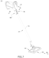
- the steam mop 10 is convertible between at least two different modes of operation, including an upright or mopping mode of operation shown in FIG. 1 , in which the handle tube 14 and base 16 are attached to the steam unit 12, and a handheld mode of operation shown in FIG. 2 , in which the handle tube 14 and base 16 are detached from the steam unit 12.
- the upright or mopping mode may be useful for cleaning floor surfaces, such as tile, linoleum, vinyl, laminate, and hardwood floors, while the handheld mode may be useful for cleaning other hard surfaces such as tiles and countertops.
- the steam delivery system can include a steam generator 22 in the form of a heater for heating liquid to at least 100 °C to generate steam, a supply tank 24 in fluid communication with an inlet 26 of the steam generator 22, a pump 28 which pressurizes the delivery system to supply liquid from the tank 24 to the steam generator 22, an actuator 30 for the pump 28 to deliver liquid on demand to the steam generator 22, and a steam distribution nozzle 32 in fluid communication with an outlet 34 of the steam generator 22 for delivering steam to a surface to be cleaned directly, or indirectly via the handle tube 14, base 16, or another cleaning tool as described in further detail below.
- the steam distribution nozzle 32 can be provided on a steam outlet conduit 36 protruding from the steam unit housing 18.
- the steam outlet conduit 36 can further mount various attachments, including the handle tube 14 and/or one or more cleaning tools described herein.
- Flexible tubing or other suitable fluid conduits 38, 40 can connect pump 28 with the steam generator inlet 26 and the steam generator outlet 34 with the steam distribution nozzle 32, respectively.
- the liquid in the supply tank 24 can comprise one or more of any suitable cleaning liquids, including, but not limited to, water or mixtures containing water.
- the supply tank 24 can be removable from the housing 18 for refilling the tank 24 with liquid, or can be refilled when on the housing 18.
- the steam distribution nozzle 32 can include at least one nozzle outlet 42 on the unit housing 18 for delivering steam to a surface to be cleaned.
- the steam distribution nozzle 32 can be in an opposing relationship to the pistol grip 20, with the steam distribution nozzle 32 on a forward end of the unit housing 18 and the pistol grip 20 a rearward end of the unit housing 18.
- a bottom 44 of the unit housing 18 can define a substantially flat surface on which the unit 12 can rest in an upright position.
- a power cord 46 which emerges from the interior of the housing 18 through a cord aperture 48, can be used to provide power to electrical components of the steam mop 10 from a source of power, such as a home power supply, upon actuation of the actuator 30.
- a source of power such as a home power supply
- the steam mop 10 can be powered by a portable power supply, such as a battery.
- FIG. 6 is an exploded view of the base 16 of the steam cleaning apparatus 10 of FIG. 1 .
- the base 16 includes a base housing 50, a swivel joint, and a steam distribution nozzle 54, where the base 16 is adapted to mount a steam cleaning pad 56 on the bottom of the base housing 50, and where the base 16 can be mounted to a distal end of the handle tube 14 ( FIG. 1 ), or alternatively, the base 16 can be mounted directly to the steam outlet conduit 36 on the steam unit 12 ( FIG. 4 ).
- the swivel joint 52 couples the base housing 50 to the handle tube 14 or steam unit 12 for movement about at least two orthogonal axes of rotation X, Y.
- the swivel joint 52 can be a universal joint.
- the swivel joint 52 includes a coupler 58 that receives one end of the handle tube 14 ( FIG. 1 ) or one end of the steam unit 12 ( FIG. 4 ), and a foot pedal 60 that is pressed to release the coupler 58 from the handle tube 14 or unit 12, respectively.
- the fluid connector 69 is configured to receive the steam distribution nozzle 32 of the steam unit 12 or the steam distribution nozzle 74 of the handle tube 14 in order to fluid connect the steam distribution nozzle 54 in the base 16 with the steam delivery system of the steam unit 12.
- the upper and lower cover 64 can together form a cradle 70 for receiving a portion of the swivel joint 52, and the cradle 70 can partially define the first axis X of the swivel joint 52.
- the handle tube 14 can comprise an elongate tubular housing 72 with a first end adapted to be attached to the steam unit 12 and a second end adapted to be attached to the base 16.
- the second end can further comprise a steam distribution nozzle 74 ( FIG. 3 ) that is in fluid communication with a steam conduit 76 ( FIG. 9 ) extending through the tubular housing 72 to the first end.
- Coupling the tubular housing 72 with the steam unit 12 places the steam conduit 76 in fluid communication with the steam delivery system, with the unit nozzle 32 supplying steam to the steam conduit 76, which in turn provides the steam to the handle nozzle 74.
- a detent latch for mounting the handle tube 14 to the steam unit 12 is provided, and may include a pivoting button 78 carried by the handle tube 14 which engages a detent 80 ( FIG. 5 ) provided on the outlet conduit 36 of the steam unit 12.
- the button 78 can be carried by the steam unit 12, with the detent 80 provided in the handle tube 14.
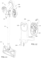
- FIG. 12 Some examples of interchangeable accessory tools that can attach to the steam distribution nozzles 32, 74 are shown in FIG. 12 , and include, but are not limited to a flat grout cleaning brush 112 for cleaning the grout in between tiles, a flat scraping tool nozzle 114 for scraping sticky messes such as gum, sap, tar, etc., an angled nozzle 116 with a narrow outlet opening for concentrating steam in tight or confined spaces, and a round brush 118 for detailing small areas such as a stove, grill, shower, or other bathroom areas.
- the brushes 112, 118 have bristles, while the nozzles 114, 116 do not Any of these tools 112-118 can be coupled with the steam distribution nozzle 32 of the steam unit 12 or the steam distribution nozzle 74 of the handle tube 14.
- a universal coupling such as a bayonet coupling can be provided on all tools 112-118 so that they can be interchangeably used with the steam mop 10.
- the handle tube 14" can comprise an elongate tubular housing 72" with a first end adapted to be attached to the steam unit 12" and a second end adapted to be attached to the base 16".
- the second end can further comprise a steam distribution nozzle (not shown) that is in fluid communication with a steam conduit 76" extending through the tubular housing 72" to the first end. Coupling the tubular housing 72" with the steam unit 12” places the steam conduit 76" in fluid communication with the steam delivery system, with the unit nozzle 32" supplying steam to the steam conduit 76", which in turn provides the steam to the base 16".
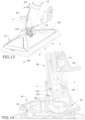
- a spring-biased control ring or actuator sleeve 160 shown herein as comprising a tubular housing, is mounted to the tube insert 150 via detent hooks 162 on an inner wall of the tubular housing that are received within corresponding recesses 164 on an outer wall of the tube insert 150.
- a spring 165 can bias the sleeve 160 toward the steam unit 12", longitudinally with respect to the handle tube 14".
- an upper rim of the sleeve 160 comprises a lug 166, for engaging a recessed track 168 on the steam outlet conduit 36".
- the track 168 shown herein comprises a T-shape, with an axial track portion 170 joined with a circumferential track portion 172, where the axial track portion 170 extends generally parallel to a longitudinal axis of the elongate tubular housing 72" and the circumferential track portion 172 extends circumferentially about the longitudinal axis of the elongate tubular housing 72".
- a first and second end recess 174, 176 are formed in the steam unit housing 18" at the ends of the circumferential track portion 172, which corresponds to a 90 degree offset around the perimeter of the steam outlet conduit 36" from the axial track portion 170.
- a third end recess 178 is axially aligned with the axial track portion 170.
- the end recesses 174, 176, 178 are sized to receive the lug 166 on the sleeve 160, which locks the handle tube 14" in one of the wide or narrow orientations.
- the user depresses the release button 152, slides the lug 166 out of the end recess 178 and into the circumferential track portion 172 by twisting the tube 14" clockwise or counter-clockwise so the lug 166 slides to either of the first or second end recess 174, 176.
- the user slides the lug 166 into the desired end recess 174, 176 at which point the release button detent 156 engages the catch 158 and locks the handle tube 14" to the steam unit 12" at 90 degrees clockwise or counterclockwise, i.e. to one of the narrow orientations where one of the short edges 84" of the base 16" faces forward.
- rotating the handle tube 14" allows the user to orient either the long edge 82" or either short edge 84" of the base 16" to face forward, depending on the cleaning need.
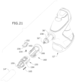
- FIGS. 23-29 show a fourth embodiment of an indexing mechanism for the steam mop 10, where like elements are referred by the same reference numeral bearing a triple prime (′′′) symbol.
- the fourth embodiment of the indexing mechanism includes a spring-biased control ring or actuator sleeve on the first end of the handle tube 14′′′ that is adapted to be attached to the steam unit 12′′′ and that permits the handle tube 14′′′ to be rotated (together with the base 16′′′) between a wide orientation where the long side 82′′′ of the base 16′′′ faces forward or a narrow orientation where the short side 84′′′ of the base 16′′′ faces forward.
- the handle tube 14′′′ can comprise an elongate tubular housing 72′′′ with a first end adapted to be attached to the steam unit 12′′′ and a second end adapted to be attached to the base 16′′′.
- the second end can further comprise a steam distribution nozzle (not shown) that is in fluid communication with a steam conduit 76′′′ extending through the tubular housing 72"' to the first end.
- Coupling the tubular housing 72′′′ with the steam unit 12′′′ places the steam conduit 76′′′ in fluid communication with the steam delivery system, with the unit nozzle 32′′′ supplying steam to the steam conduit 76′′′, which in turn provides the steam to the base 16′′′.
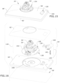
- a detent latch for mounting the handle tube 14′′′ to the steam unit 12′′′ can be provided, and may be provided via an adapter housing 180 provided at a first or proximal end of the handle tube 14"'.
- the adapter housing 180 includes a pivoting release button 182 biased by a spring 194 for selectively securing the handle tube 14′′′ to the steam outlet conduit 36′′′ on the steam unit 12′′′.
- the release button 182 includes a catch 186 for retaining a detent 188 on the steam outlet conduit 36"'. When the release button 182 is depressed, the catch 186 disengages from the detent 188 and the entire handle tube 14′′′ can be removed from the steam unit 12"'.
- the tube insert 190 comprises a cylindrical body that is configured to retain the connector 192 within the handle tube 14′′′.
- the tube insert 190 has detents 198 on an outer portion that are received within detent openings 200 in the tubular housing 72"'.
- the tube insert 190 is configured to be press fit securely into the tubular housing 72".
- An inner flange 202 on a lower portion of the tube insert 190 comprises a proximal flange surface 204 and a distal flange surface 206, the proximal flange surface 204 oriented towards the first end of the handle tube 14′′′ and the distal flange surface 206 oriented towards the second end of the handle tube 14"'.
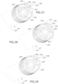
- FIGS. 27-29 are rear perspective views showing the actuator sleeve 196 in various positions during the indexing.
- the adapter housing 180 and steam unit 12′′′ have been removed for clarity.
- FIG. 27 shows the actuator sleeve 196 in a proximal or home position, as shown in FIG. 25 , where the sleeve 196 is biased by the spring 194 toward the adapter housing 180 and steam unit 12′′′ and the handle tube 14" is in the wide orientation.
- FIG. 28 shows the actuator sleeve 196 in a retracted position in which the handle tube 14′′′ is free to index between the wide and narrow orientations.
- FIG. 29 shows the actuator sleeve 196 in a proximal or home position where the handle tube 14" is in the narrow orientation.
- Another advantage of the present disclosure is that embodiments of the base 16, 16', base 16", base 16′′′ described above can quickly be indexed between different orientations, depending on the size of the area to be cleaned.
- Another advantage of the present disclosure is that the interchangeable tools and tool caddy provide flexible application to different cleaning tasks in a user's home.
- steam unit 12 shown in the illustrated embodiment offers a more ergonomic and comfortable gripping position, with the pistol-style grip 20 positioned at the rear of the unit.
- aspects of the invention may be used on other types of steam mops and steam cleaners, including non-convertible steam cleaners. Still further, aspects of the invention may also be used on surface cleaning apparatus other than steam cleaners, such as an apparatus configured to deliver liquid rather than steam.
Landscapes
- Cleaning Implements For Floors, Carpets, Furniture, Walls, And The Like (AREA)
- Cleaning By Liquid Or Steam (AREA)
- Cleaning In General (AREA)
Applications Claiming Priority (2)
| Application Number | Priority Date | Filing Date | Title |
|---|---|---|---|
| US201762452699P | 2017-01-31 | 2017-01-31 | |
| EP18153606.1A EP3354182B1 (en) | 2017-01-31 | 2018-01-26 | Steam cleaning apparatus |
Related Parent Applications (1)
| Application Number | Title | Priority Date | Filing Date |
|---|---|---|---|
| EP18153606.1A Division EP3354182B1 (en) | 2017-01-31 | 2018-01-26 | Steam cleaning apparatus |
Publications (2)
| Publication Number | Publication Date |
|---|---|
| EP3875015A1 EP3875015A1 (en) | 2021-09-08 |
| EP3875015B1 true EP3875015B1 (en) | 2025-04-16 |
Family
ID=61054215
Family Applications (2)
| Application Number | Title | Priority Date | Filing Date |
|---|---|---|---|
| EP21167652.3A Active EP3875015B1 (en) | 2017-01-31 | 2018-01-26 | Steam cleaning apparatus |
| EP18153606.1A Active EP3354182B1 (en) | 2017-01-31 | 2018-01-26 | Steam cleaning apparatus |
Family Applications After (1)
| Application Number | Title | Priority Date | Filing Date |
|---|---|---|---|
| EP18153606.1A Active EP3354182B1 (en) | 2017-01-31 | 2018-01-26 | Steam cleaning apparatus |
Country Status (7)
| Country | Link |
|---|---|
| US (2) | US10791903B2 (pl) |
| EP (2) | EP3875015B1 (pl) |
| CN (2) | CN108371524B (pl) |
| AU (1) | AU2018200678B2 (pl) |
| ES (1) | ES2884260T3 (pl) |
| PL (1) | PL3354182T3 (pl) |
| PT (1) | PT3354182T (pl) |
Families Citing this family (21)
| Publication number | Priority date | Publication date | Assignee | Title |
|---|---|---|---|---|
| US10702116B2 (en) | 2017-09-15 | 2020-07-07 | Omachron Intellectual Property Inc. | Surface cleaning apparatus |
| CA3101161A1 (en) | 2019-12-09 | 2021-06-09 | Bissell Inc. | Surface cleaning apparatus |
| USD912354S1 (en) * | 2020-01-31 | 2021-03-02 | Vornado Air, Llc | Steam mop |
| EP4106594B1 (en) * | 2020-02-20 | 2024-04-17 | Techtronic Floor Care Technology Limited | Floor cleaner |
| CN111973087B (zh) * | 2020-08-19 | 2021-11-30 | 浙江明鹏新能源科技有限公司 | 清扫系统及清洁机器人 |
| CN112754378B (zh) * | 2021-01-29 | 2025-06-20 | 广东天物新材料科技有限公司 | 一种连接结构及包含该连接结构的蒸汽地拖 |
| DE102021103489B4 (de) | 2021-02-15 | 2022-12-15 | Leifheit Aktiengesellschaft | Reinigungsgerät |
| CA3152680C (en) | 2021-03-17 | 2025-02-11 | Dupray Ventures Inc. | STAIN REMOVAL DEVICE |
| USD995963S1 (en) * | 2021-06-11 | 2023-08-15 | Bissell Inc. | Vacuum cleaner |
| USD995964S1 (en) * | 2021-06-11 | 2023-08-15 | Bissell Inc. | Vacuum cleaner |
| USD1017156S1 (en) | 2022-05-09 | 2024-03-05 | Dupray Ventures Inc. | Cleaner |
| USD1054131S1 (en) * | 2022-09-16 | 2024-12-10 | Lg Electronics Inc. | Vacuum cleaner body |
| USD1047321S1 (en) * | 2022-09-30 | 2024-10-15 | Guangdong Well Technology Co., Ltd | Hand-held vacuum cleaner |
| DE102023105940A1 (de) * | 2023-03-09 | 2024-09-12 | Alfred Kärcher SE & Co. KG | Gerät und modul und verwendung eines moduls |
| EP4716491A1 (en) | 2023-05-23 | 2026-04-01 | SharkNinja Operating LLC | Cleaning apparatus |
| USD1088383S1 (en) * | 2023-05-25 | 2025-08-12 | Samsung Electronics Co., Ltd. | Spin mop brush for cleaner |
| USD1105672S1 (en) | 2023-08-30 | 2025-12-09 | Sharkninja Operating Llc | Vacuum cleaner and vacuum nozzle |
| USD1113019S1 (en) | 2024-05-31 | 2026-02-10 | Sharkninja Operating Llc | Steam cleaner |
| USD1052206S1 (en) * | 2024-06-26 | 2024-11-19 | Zhongshan Kamshing Home Electrical Appliance Co., Ltd | Steam generator for steam mop |
| USD1080113S1 (en) * | 2024-12-23 | 2025-06-17 | Qihui Xie | Steam mop |
| USD1081051S1 (en) * | 2025-03-06 | 2025-06-24 | Qihui Xie | Steam mop |
Family Cites Families (33)
| Publication number | Priority date | Publication date | Assignee | Title |
|---|---|---|---|---|
| EP0253910B1 (en) | 1986-07-21 | 1991-09-18 | ELWATT S.r.l. | Steam cleaning apparatus |
| DE4309432A1 (de) * | 1993-03-24 | 1994-09-29 | Vorwerk Co Interholding | Gelenkverbindung für ein Haushaltsgerät wie insbesondere einen Staubsauger, ein Dampfreinigungsgerät oder dergleichen |
| GB2276811B (en) | 1993-03-31 | 1997-02-05 | Gold Star Co | Steam vacuum cleaner and cleaning method thereof |
| HU216371B (hu) | 1996-09-23 | 1999-06-28 | Levente Fülöp | Stabil makromolekuláris diszperz rendszerű, vizet tartalmazó folyékony üzemanyag-készítmény belső égésű motorok hibrid motorként történő működtetésére, valamint eljárás a készítmény előállítására |
| US5779155A (en) * | 1996-11-26 | 1998-07-14 | The Procter & Gamble Company | Decoupled liquid delivery system |
| FR2762531B1 (fr) | 1997-04-28 | 1999-08-13 | Superba Sa | Appareil portable omnidirectionnel de nettoyage a la vapeur de surfaces dures ou souples |
| GB9816037D0 (en) * | 1998-07-23 | 1998-09-23 | Addis Housewares Ltd | A mop |
| TW578540U (en) * | 1998-07-28 | 2004-03-01 | Sharp Kk | Electric vacuum cleaner and nozzle unit therefor |
| EP1106728A1 (de) * | 1999-12-04 | 2001-06-13 | Theo Krebs AG | Verfahren und Vorrichtung zur lokalen Reinigung von textilen Flächengebilden |
| CN2500247Y (zh) * | 2001-09-12 | 2002-07-17 | 深圳市宝安区龙华隆升塑胶五金加工厂 | 高压蒸汽式消毒清洗机 |
| CN1386590A (zh) * | 2002-06-20 | 2002-12-25 | 张和君 | 手提式蒸汽清洁枪 |
| US20040146332A1 (en) * | 2003-01-27 | 2004-07-29 | Top Innovations, Inc. | Telescoping cleaning apparatus with refillable fluid reservoir and interchangeable heads |
| CN1845697A (zh) * | 2003-09-03 | 2006-10-11 | 宝洁公司 | 多表面清洁工具 |
| ITGE20050009A1 (it) | 2005-02-09 | 2006-08-10 | Ariete Spa | Apparecchio pulitore a vapore |
| US7380307B2 (en) * | 2006-01-25 | 2008-06-03 | Mei-Hua Tsai | Steam cleaning device |
| US20080022480A1 (en) * | 2006-07-28 | 2008-01-31 | Main Power Electrical Factory Ltd. | Handheld steam cleaner |
| US7516565B1 (en) * | 2008-03-20 | 2009-04-14 | Samson Tsen | Steam channeling structure |
| US8052342B2 (en) * | 2008-05-09 | 2011-11-08 | Euro-Pro Operating Llc | Universal connector for a fluid mop |
| US20110073135A1 (en) * | 2009-09-25 | 2011-03-31 | Euro-Pro Operating, Llc | Steam appliance |
| DE102011000454A1 (de) * | 2010-02-04 | 2011-08-04 | Vorwerk & Co. Interholding GmbH, 42275 | Saugdüse für einen elektromotorisch betriebenen Staubsauger |
| AU2012201161B2 (en) | 2011-03-04 | 2014-04-17 | Bissell Inc. | Surface cleaning apparatus with pivoting manifold |
| AU2013201282B2 (en) | 2012-03-09 | 2014-06-19 | Bissell Inc. | Surface cleaning apparatus |
| CN202960391U (zh) * | 2012-11-27 | 2013-06-05 | 莱克电气股份有限公司 | 具有新型附件的蒸汽清洁器具 |
| AU2014100145A4 (en) | 2013-03-01 | 2014-03-13 | Bissell Inc. | Surface cleaning apparatus |
| CA2843333C (en) | 2013-03-01 | 2021-05-04 | Bissell Homecare, Inc. | Vacuum cleaner with accessory tool assembly |
| CN203483362U (zh) * | 2013-09-17 | 2014-03-19 | 苏州欧赛电器有限公司 | 一种手持蒸汽清洁器壳体 |
| DE202013105041U1 (de) * | 2013-11-08 | 2014-01-17 | Bendel Werkzeuge Inh. Frank Bendel | Reinigungsgerät |
| CN103654634A (zh) * | 2013-11-26 | 2014-03-26 | 苏州欧赛电器有限公司 | 一种多功能手持式蒸汽清洁器 |
| GB2522668B (en) | 2014-01-31 | 2017-05-17 | Techtronic Floor Care Tech Ltd | Surface cleaning apparatus |
| CN104042168B (zh) * | 2014-04-05 | 2017-08-29 | 胡建芬 | 一种手提式蒸汽清洗机 |
| CN204164540U (zh) * | 2014-09-18 | 2015-02-18 | 佛山市顺德区盛熙电器制造有限公司 | 蒸汽清洁机的蒸汽管接头组件 |
| AU2017100144A4 (en) | 2016-02-17 | 2017-03-02 | Bissell Inc. | Surface cleaning apparatus |
| CN105816121A (zh) * | 2016-06-03 | 2016-08-03 | 江苏纽唯盛机电有限公司 | 一种无线蒸汽拖把及其使用方法 |
-
2018
- 2018-01-26 EP EP21167652.3A patent/EP3875015B1/en active Active
- 2018-01-26 PT PT181536061T patent/PT3354182T/pt unknown
- 2018-01-26 PL PL18153606T patent/PL3354182T3/pl unknown
- 2018-01-26 EP EP18153606.1A patent/EP3354182B1/en active Active
- 2018-01-26 ES ES18153606T patent/ES2884260T3/es active Active
- 2018-01-30 CN CN201810091075.3A patent/CN108371524B/zh active Active
- 2018-01-30 AU AU2018200678A patent/AU2018200678B2/en active Active
- 2018-01-30 CN CN202110687901.2A patent/CN113331757A/zh active Pending
- 2018-01-31 US US15/885,135 patent/US10791903B2/en active Active
-
2020
- 2020-10-05 US US17/062,899 patent/US11793386B2/en active Active
Also Published As
| Publication number | Publication date |
|---|---|
| US11793386B2 (en) | 2023-10-24 |
| US10791903B2 (en) | 2020-10-06 |
| US20210038048A1 (en) | 2021-02-11 |
| US20180213995A1 (en) | 2018-08-02 |
| ES2884260T3 (es) | 2021-12-10 |
| EP3354182B1 (en) | 2021-05-05 |
| EP3875015A1 (en) | 2021-09-08 |
| AU2018200678A1 (en) | 2018-08-16 |
| PL3354182T3 (pl) | 2021-09-27 |
| CN108371524A (zh) | 2018-08-07 |
| EP3354182A1 (en) | 2018-08-01 |
| CN108371524B (zh) | 2021-07-02 |
| PT3354182T (pt) | 2021-07-07 |
| CN113331757A (zh) | 2021-09-03 |
| AU2018200678B2 (en) | 2023-05-25 |
Similar Documents
| Publication | Publication Date | Title |
|---|---|---|
| US11793386B2 (en) | Steam cleaning apparatus | |
| US12059110B2 (en) | Motorized floor mop | |
| US11844476B2 (en) | Extraction cleaner | |
| CN105916426B (zh) | 表面清洁设备 | |
| EP2464270B1 (en) | Upright steam mop with auxiliary hand tool | |
| US8534301B2 (en) | Steam mop | |
| US9743819B2 (en) | Floor mop with concentrated cleaning feature | |
| US20150089757A1 (en) | Floor mop with removable base plate | |
| CN206995197U (zh) | 地板处理设备 | |
| US20150082565A1 (en) | Sliding scrub brush for a floor mop | |
| EP2846673A2 (en) | Steam cleaners | |
| WO2025130803A1 (zh) | 一种表面清洁设备 | |
| GB2545724A (en) | A surface cleaning apparatus |
Legal Events
| Date | Code | Title | Description |
|---|---|---|---|
| PUAI | Public reference made under article 153(3) epc to a published international application that has entered the european phase |
Free format text: ORIGINAL CODE: 0009012 |
|
| STAA | Information on the status of an ep patent application or granted ep patent |
Free format text: STATUS: THE APPLICATION HAS BEEN PUBLISHED |
|
| AC | Divisional application: reference to earlier application |
Ref document number: 3354182 Country of ref document: EP Kind code of ref document: P |
|
| AK | Designated contracting states |
Kind code of ref document: A1 Designated state(s): AL AT BE BG CH CY CZ DE DK EE ES FI FR GB GR HR HU IE IS IT LI LT LU LV MC MK MT NL NO PL PT RO RS SE SI SK SM TR |
|
| RAP1 | Party data changed (applicant data changed or rights of an application transferred) |
Owner name: BISSELL INC. |
|
| STAA | Information on the status of an ep patent application or granted ep patent |
Free format text: STATUS: REQUEST FOR EXAMINATION WAS MADE |
|
| 17P | Request for examination filed |
Effective date: 20220303 |
|
| RBV | Designated contracting states (corrected) |
Designated state(s): AL AT BE BG CH CY CZ DE DK EE ES FI FR GB GR HR HU IE IS IT LI LT LU LV MC MK MT NL NO PL PT RO RS SE SI SK SM TR |
|
| P01 | Opt-out of the competence of the unified patent court (upc) registered |
Effective date: 20230528 |
|
| STAA | Information on the status of an ep patent application or granted ep patent |
Free format text: STATUS: EXAMINATION IS IN PROGRESS |
|
| 17Q | First examination report despatched |
Effective date: 20240524 |
|
| GRAP | Despatch of communication of intention to grant a patent |
Free format text: ORIGINAL CODE: EPIDOSNIGR1 |
|
| STAA | Information on the status of an ep patent application or granted ep patent |
Free format text: STATUS: GRANT OF PATENT IS INTENDED |
|
| INTG | Intention to grant announced |
Effective date: 20250109 |
|
| RIN1 | Information on inventor provided before grant (corrected) |
Inventor name: LUO, MING Inventor name: YANG, JING Inventor name: LI, CHI KEUNG Inventor name: KREBS, ALAN J. |
|
| GRAS | Grant fee paid |
Free format text: ORIGINAL CODE: EPIDOSNIGR3 |
|
| GRAA | (expected) grant |
Free format text: ORIGINAL CODE: 0009210 |
|
| STAA | Information on the status of an ep patent application or granted ep patent |
Free format text: STATUS: THE PATENT HAS BEEN GRANTED |
|
| AC | Divisional application: reference to earlier application |
Ref document number: 3354182 Country of ref document: EP Kind code of ref document: P |
|
| AK | Designated contracting states |
Kind code of ref document: B1 Designated state(s): AL AT BE BG CH CY CZ DE DK EE ES FI FR GB GR HR HU IE IS IT LI LT LU LV MC MK MT NL NO PL PT RO RS SE SI SK SM TR |
|
| REG | Reference to a national code |
Ref country code: GB Ref legal event code: FG4D |
|
| REG | Reference to a national code |
Ref country code: CH Ref legal event code: EP |
|
| REG | Reference to a national code |
Ref country code: IE Ref legal event code: FG4D |
|
| REG | Reference to a national code |
Ref country code: DE Ref legal event code: R096 Ref document number: 602018081239 Country of ref document: DE |
|
| REG | Reference to a national code |
Ref country code: NL Ref legal event code: FP |
|
| REG | Reference to a national code |
Ref country code: AT Ref legal event code: MK05 Ref document number: 1784933 Country of ref document: AT Kind code of ref document: T Effective date: 20250416 |
|
| PG25 | Lapsed in a contracting state [announced via postgrant information from national office to epo] |
Ref country code: PT Free format text: LAPSE BECAUSE OF FAILURE TO SUBMIT A TRANSLATION OF THE DESCRIPTION OR TO PAY THE FEE WITHIN THE PRESCRIBED TIME-LIMIT Effective date: 20250818 Ref country code: ES Free format text: LAPSE BECAUSE OF FAILURE TO SUBMIT A TRANSLATION OF THE DESCRIPTION OR TO PAY THE FEE WITHIN THE PRESCRIBED TIME-LIMIT Effective date: 20250416 Ref country code: FI Free format text: LAPSE BECAUSE OF FAILURE TO SUBMIT A TRANSLATION OF THE DESCRIPTION OR TO PAY THE FEE WITHIN THE PRESCRIBED TIME-LIMIT Effective date: 20250416 |
|
| REG | Reference to a national code |
Ref country code: LT Ref legal event code: MG9D |
|
| PG25 | Lapsed in a contracting state [announced via postgrant information from national office to epo] |
Ref country code: GR Free format text: LAPSE BECAUSE OF FAILURE TO SUBMIT A TRANSLATION OF THE DESCRIPTION OR TO PAY THE FEE WITHIN THE PRESCRIBED TIME-LIMIT Effective date: 20250717 Ref country code: NO Free format text: LAPSE BECAUSE OF FAILURE TO SUBMIT A TRANSLATION OF THE DESCRIPTION OR TO PAY THE FEE WITHIN THE PRESCRIBED TIME-LIMIT Effective date: 20250716 |
|
| PG25 | Lapsed in a contracting state [announced via postgrant information from national office to epo] |
Ref country code: PL Free format text: LAPSE BECAUSE OF FAILURE TO SUBMIT A TRANSLATION OF THE DESCRIPTION OR TO PAY THE FEE WITHIN THE PRESCRIBED TIME-LIMIT Effective date: 20250416 |
|
| PG25 | Lapsed in a contracting state [announced via postgrant information from national office to epo] |
Ref country code: BG Free format text: LAPSE BECAUSE OF FAILURE TO SUBMIT A TRANSLATION OF THE DESCRIPTION OR TO PAY THE FEE WITHIN THE PRESCRIBED TIME-LIMIT Effective date: 20250416 |
|
| PG25 | Lapsed in a contracting state [announced via postgrant information from national office to epo] |
Ref country code: HR Free format text: LAPSE BECAUSE OF FAILURE TO SUBMIT A TRANSLATION OF THE DESCRIPTION OR TO PAY THE FEE WITHIN THE PRESCRIBED TIME-LIMIT Effective date: 20250416 |
|
| PG25 | Lapsed in a contracting state [announced via postgrant information from national office to epo] |
Ref country code: AT Free format text: LAPSE BECAUSE OF FAILURE TO SUBMIT A TRANSLATION OF THE DESCRIPTION OR TO PAY THE FEE WITHIN THE PRESCRIBED TIME-LIMIT Effective date: 20250416 |
|
| PG25 | Lapsed in a contracting state [announced via postgrant information from national office to epo] |
Ref country code: RS Free format text: LAPSE BECAUSE OF FAILURE TO SUBMIT A TRANSLATION OF THE DESCRIPTION OR TO PAY THE FEE WITHIN THE PRESCRIBED TIME-LIMIT Effective date: 20250716 |
|
| PG25 | Lapsed in a contracting state [announced via postgrant information from national office to epo] |
Ref country code: IS Free format text: LAPSE BECAUSE OF FAILURE TO SUBMIT A TRANSLATION OF THE DESCRIPTION OR TO PAY THE FEE WITHIN THE PRESCRIBED TIME-LIMIT Effective date: 20250816 |
|
| PG25 | Lapsed in a contracting state [announced via postgrant information from national office to epo] |
Ref country code: LV Free format text: LAPSE BECAUSE OF FAILURE TO SUBMIT A TRANSLATION OF THE DESCRIPTION OR TO PAY THE FEE WITHIN THE PRESCRIBED TIME-LIMIT Effective date: 20250416 |
|
| PGFP | Annual fee paid to national office [announced via postgrant information from national office to epo] |
Ref country code: GB Payment date: 20251217 Year of fee payment: 9 |
|
| PG25 | Lapsed in a contracting state [announced via postgrant information from national office to epo] |
Ref country code: SM Free format text: LAPSE BECAUSE OF FAILURE TO SUBMIT A TRANSLATION OF THE DESCRIPTION OR TO PAY THE FEE WITHIN THE PRESCRIBED TIME-LIMIT Effective date: 20250416 Ref country code: DK Free format text: LAPSE BECAUSE OF FAILURE TO SUBMIT A TRANSLATION OF THE DESCRIPTION OR TO PAY THE FEE WITHIN THE PRESCRIBED TIME-LIMIT Effective date: 20250416 |
|
| PGFP | Annual fee paid to national office [announced via postgrant information from national office to epo] |
Ref country code: NL Payment date: 20251217 Year of fee payment: 9 Ref country code: FR Payment date: 20251217 Year of fee payment: 9 |
|
| REG | Reference to a national code |
Ref country code: DE Ref legal event code: R097 Ref document number: 602018081239 Country of ref document: DE |
|
| PG25 | Lapsed in a contracting state [announced via postgrant information from national office to epo] |
Ref country code: CZ Free format text: LAPSE BECAUSE OF FAILURE TO SUBMIT A TRANSLATION OF THE DESCRIPTION OR TO PAY THE FEE WITHIN THE PRESCRIBED TIME-LIMIT Effective date: 20250416 |
|
| PG25 | Lapsed in a contracting state [announced via postgrant information from national office to epo] |
Ref country code: EE Free format text: LAPSE BECAUSE OF FAILURE TO SUBMIT A TRANSLATION OF THE DESCRIPTION OR TO PAY THE FEE WITHIN THE PRESCRIBED TIME-LIMIT Effective date: 20250416 |
|
| PG25 | Lapsed in a contracting state [announced via postgrant information from national office to epo] |
Ref country code: RO Free format text: LAPSE BECAUSE OF FAILURE TO SUBMIT A TRANSLATION OF THE DESCRIPTION OR TO PAY THE FEE WITHIN THE PRESCRIBED TIME-LIMIT Effective date: 20250416 Ref country code: SK Free format text: LAPSE BECAUSE OF FAILURE TO SUBMIT A TRANSLATION OF THE DESCRIPTION OR TO PAY THE FEE WITHIN THE PRESCRIBED TIME-LIMIT Effective date: 20250416 |
|
| PG25 | Lapsed in a contracting state [announced via postgrant information from national office to epo] |
Ref country code: IT Free format text: LAPSE BECAUSE OF FAILURE TO SUBMIT A TRANSLATION OF THE DESCRIPTION OR TO PAY THE FEE WITHIN THE PRESCRIBED TIME-LIMIT Effective date: 20250416 |
|
| PLBE | No opposition filed within time limit |
Free format text: ORIGINAL CODE: 0009261 |
|
| STAA | Information on the status of an ep patent application or granted ep patent |
Free format text: STATUS: NO OPPOSITION FILED WITHIN TIME LIMIT |
|
| REG | Reference to a national code |
Ref country code: CH Ref legal event code: L10 Free format text: ST27 STATUS EVENT CODE: U-0-0-L10-L00 (AS PROVIDED BY THE NATIONAL OFFICE) Effective date: 20260225 |
|
| 26N | No opposition filed |
Effective date: 20260119 |
|
| PGFP | Annual fee paid to national office [announced via postgrant information from national office to epo] |
Ref country code: DE Payment date: 20251217 Year of fee payment: 9 |