EP3354182B1 - Steam cleaning apparatus - Google Patents
Steam cleaning apparatus Download PDFInfo
- Publication number
- EP3354182B1 EP3354182B1 EP18153606.1A EP18153606A EP3354182B1 EP 3354182 B1 EP3354182 B1 EP 3354182B1 EP 18153606 A EP18153606 A EP 18153606A EP 3354182 B1 EP3354182 B1 EP 3354182B1
- Authority
- EP
- European Patent Office
- Prior art keywords
- steam
- base
- handle tube
- cleaning apparatus
- housing
- Prior art date
- Legal status (The legal status is an assumption and is not a legal conclusion. Google has not performed a legal analysis and makes no representation as to the accuracy of the status listed.)
- Active
Links
- 238000013020 steam cleaning Methods 0.000 title claims description 45
- 238000009826 distribution Methods 0.000 claims description 38
- 230000007246 mechanism Effects 0.000 claims description 32
- 230000008878 coupling Effects 0.000 claims description 18
- 238000010168 coupling process Methods 0.000 claims description 18
- 238000005859 coupling reaction Methods 0.000 claims description 18
- 239000012530 fluid Substances 0.000 claims description 18
- 238000004891 communication Methods 0.000 claims description 12
- 238000004140 cleaning Methods 0.000 description 25
- 239000007788 liquid Substances 0.000 description 7
- 230000006835 compression Effects 0.000 description 5
- 238000007906 compression Methods 0.000 description 5
- 230000008901 benefit Effects 0.000 description 4
- XLYOFNOQVPJJNP-UHFFFAOYSA-N water Substances O XLYOFNOQVPJJNP-UHFFFAOYSA-N 0.000 description 4
- 239000011121 hardwood Substances 0.000 description 3
- 125000000391 vinyl group Chemical group [H]C([*])=C([H])[H] 0.000 description 3
- 229920002554 vinyl polymer Polymers 0.000 description 3
- 230000000994 depressogenic effect Effects 0.000 description 2
- 239000011440 grout Substances 0.000 description 2
- 238000010438 heat treatment Methods 0.000 description 2
- 238000007790 scraping Methods 0.000 description 2
- -1 but not limited to Substances 0.000 description 1
- 239000000428 dust Substances 0.000 description 1
- 238000005304 joining Methods 0.000 description 1
- 238000000034 method Methods 0.000 description 1
- 239000000203 mixture Substances 0.000 description 1
- 230000037361 pathway Effects 0.000 description 1
- 230000008569 process Effects 0.000 description 1
- 230000000717 retained effect Effects 0.000 description 1
- 238000003860 storage Methods 0.000 description 1
Images


Classifications
-
- A—HUMAN NECESSITIES
- A47—FURNITURE; DOMESTIC ARTICLES OR APPLIANCES; COFFEE MILLS; SPICE MILLS; SUCTION CLEANERS IN GENERAL
- A47L—DOMESTIC WASHING OR CLEANING; SUCTION CLEANERS IN GENERAL
- A47L11/00—Machines for cleaning floors, carpets, furniture, walls, or wall coverings
- A47L11/40—Parts or details of machines not provided for in groups A47L11/02 - A47L11/38, or not restricted to one of these groups, e.g. handles, arrangements of switches, skirts, buffers, levers
- A47L11/408—Means for supplying cleaning or surface treating agents
- A47L11/4086—Arrangements for steam generation
-
- A—HUMAN NECESSITIES
- A47—FURNITURE; DOMESTIC ARTICLES OR APPLIANCES; COFFEE MILLS; SPICE MILLS; SUCTION CLEANERS IN GENERAL
- A47L—DOMESTIC WASHING OR CLEANING; SUCTION CLEANERS IN GENERAL
- A47L13/00—Implements for cleaning floors, carpets, furniture, walls, or wall coverings
- A47L13/10—Scrubbing; Scouring; Cleaning; Polishing
- A47L13/20—Mops
- A47L13/22—Mops with liquid-feeding devices
- A47L13/225—Steam mops
-
- A—HUMAN NECESSITIES
- A47—FURNITURE; DOMESTIC ARTICLES OR APPLIANCES; COFFEE MILLS; SPICE MILLS; SUCTION CLEANERS IN GENERAL
- A47L—DOMESTIC WASHING OR CLEANING; SUCTION CLEANERS IN GENERAL
- A47L11/00—Machines for cleaning floors, carpets, furniture, walls, or wall coverings
- A47L11/34—Machines for treating carpets in position by liquid, foam, or vapour, e.g. by steam
-
- A—HUMAN NECESSITIES
- A47—FURNITURE; DOMESTIC ARTICLES OR APPLIANCES; COFFEE MILLS; SPICE MILLS; SUCTION CLEANERS IN GENERAL
- A47L—DOMESTIC WASHING OR CLEANING; SUCTION CLEANERS IN GENERAL
- A47L11/00—Machines for cleaning floors, carpets, furniture, walls, or wall coverings
- A47L11/40—Parts or details of machines not provided for in groups A47L11/02 - A47L11/38, or not restricted to one of these groups, e.g. handles, arrangements of switches, skirts, buffers, levers
- A47L11/4075—Handles; levers
-
- A—HUMAN NECESSITIES
- A47—FURNITURE; DOMESTIC ARTICLES OR APPLIANCES; COFFEE MILLS; SPICE MILLS; SUCTION CLEANERS IN GENERAL
- A47L—DOMESTIC WASHING OR CLEANING; SUCTION CLEANERS IN GENERAL
- A47L11/00—Machines for cleaning floors, carpets, furniture, walls, or wall coverings
- A47L11/40—Parts or details of machines not provided for in groups A47L11/02 - A47L11/38, or not restricted to one of these groups, e.g. handles, arrangements of switches, skirts, buffers, levers
- A47L11/408—Means for supplying cleaning or surface treating agents
- A47L11/4083—Liquid supply reservoirs; Preparation of the agents, e.g. mixing devices
-
- A—HUMAN NECESSITIES
- A47—FURNITURE; DOMESTIC ARTICLES OR APPLIANCES; COFFEE MILLS; SPICE MILLS; SUCTION CLEANERS IN GENERAL
- A47L—DOMESTIC WASHING OR CLEANING; SUCTION CLEANERS IN GENERAL
- A47L13/00—Implements for cleaning floors, carpets, furniture, walls, or wall coverings
- A47L13/10—Scrubbing; Scouring; Cleaning; Polishing
- A47L13/42—Details
-
- B—PERFORMING OPERATIONS; TRANSPORTING
- B08—CLEANING
- B08B—CLEANING IN GENERAL; PREVENTION OF FOULING IN GENERAL
- B08B2230/00—Other cleaning aspects applicable to all B08B range
- B08B2230/01—Cleaning with steam
Definitions
- Steam cleaning apparatus with steam delivery such as steam mops
- Typical steam mops have a reservoir for storing water that is fluidly connected to a selectively engageable pump or valve.
- the pump or valve outlet is fluidly connected to a steam boiler with a heating element to heat the water.
- the steam boiler generates steam, which is directed towards the surface to be cleaned through a nozzle or manifold mounted in a foot assembly that engages the floor surface.
- Steam is typically applied to the backside of a cleaning pad attached to the foot assembly. Steam vapor eventually saturates the entire cleaning pad as the moisture wicks outwardly from the point of steam application.
- EP 0 616 790 A2 discloses a steam cleaner having a steam unit within a housing, a device handle, and a base coupled with the device handle via an articulated connection.
- the tube-like device handle is provided at one end with a handle grip and the other end with a working attachment or base, via the hinge connection with a working attachment.
- GB 2 522 668 A discloses a steam cleaner having a cleaning head and a steam unit connected by an elongate member.
- the connection of the elongate member to the cleaning head is by way of a universal-type joint, which permits 360° articulation therebetween.
- Other types of hinge are envisaged, e.g. those which permit less than 360° articulation.
- First and second locking members releasably connect the elongate member to the cleaning head and steam unit, respectively.
- a steam cleaning apparatus includes a steam unit, an elongated handle tube coupled with an outlet of the steam unit, a base coupled with the handle tube and adapted to move over a surface to be cleaned in a direction of travel, the base having a base housing with a long edge and a short edge that is shorter than the long edge, and an indexing mechanism configured to move at least the base housing between a wide orientation where the long edge of the base housing is orthogonal to the direction of travel and a narrow orientation where the short edge of the base housing is orthogonal to the direction of travel.
- the invention relates to a surface cleaning apparatus such as a steam cleaning apparatus or steam mop, for steam cleaning surfaces. More specifically, the invention relates to a steam mop that can be converted into different use configurations, including hand-held use.
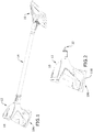
- FIG. 1 is a perspective view of a steam cleaning apparatus 10 according to one embodiment of the invention.
- the steam cleaning apparatus 10 of the illustrated embodiment may alternatively be referred to herein as a steam mop, and includes a steam unit 12, a detachable handle tube 14 and a base 16 adapted to move over a surface to be cleaned.
- the steam mop 10 can generate and deliver steam to a surface to be cleaned, including floor surfaces, such as tile, linoleum, vinyl, laminate, and hardwood floors, and other hard surfaces such as tiles and countertops.
- the steam mop 10 is convertible between different modes of operation to efficiently clean different surface types and hard-to-reach areas.
- the terms “upper,” “lower,” “right,” “left,” “rear,” “front,” “vertical,” “horizontal,” “inner,” “outer,” and derivatives thereof shall relate to the invention as oriented in FIG. 1 from the perspective of a user behind the steam unit 12 and holding the steam unit 12 by its grip, which defines a rear of the steam unit 12 or steam cleaning apparatus.
- the invention may assume various alternative orientations, except where expressly specified to the contrary.
- the steam unit 12 can comprise a modular, handheld steam unit 12 that can be used independently of the handle tube 14 and base 16 to clean a surface.
- the handle tube 14 and base 16 are removable or detachable from the steam unit 12.
- the steam mop 10 is convertible between at least two different modes of operation, including an upright or mopping mode of operation shown in FIG. 1 , in which the handle tube 14 and base 16 are attached to the steam unit 12, and a handheld mode of operation shown in FIG. 2 , in which the handle tube 14 and base 16 are detached from the steam unit 12.
- the upright or mopping mode may be useful for cleaning floor surfaces, such as tile, linoleum, vinyl, laminate, and hardwood floors, while the handheld mode may be useful for cleaning other hard surfaces such as tiles and countertops.
- the steam mop 10 can further be provided with other modes of operation, such as a remote cleaning mode of operation, shown in FIG. 3 , in which the handle tube 14 is attached to the steam unit 12 and the base 16 is removed, which allows the steam mop 10 to clean remote or hard to reach areas.
- a remote cleaning mode of operation shown in FIG. 3
- Another mode of operation is a handheld accessory mode of operation, one example of which is shown in FIG. 4 , in which the handle tube 14 is detached from the steam unit 12, and a cleaning accessory tool is attached in its place.
- the base 16 itself can be directly attached to the steam unit 12.
- Other examples of accessory tools that can be used in the handheld accessory mode are shown in FIG. 12 .
- FIG. 5 is a cross-sectional view through the steam unit 12 of the steam cleaning apparatus 10 of FIG. 1 .
- the steam unit 12 can comprise a housing 18 with a pistol-style grip 20 and which carries a steam delivery system for generating steam and delivering the steam to a surface to be cleaned.
- the steam delivery system can include a steam generator 22 in the form of a heater for heating liquid to at least 100 °C to generate steam, a supply tank 24 in fluid communication with an inlet 26 of the steam generator 22, a pump 28 which pressurizes the delivery system to supply liquid from the tank 24 to the steam generator 22, an actuator 30 for the pump 28 to deliver liquid on demand to the steam generator 22, and a steam distribution nozzle 32 in fluid communication with an outlet 34 of the steam generator 22 for delivering steam to a surface to be cleaned directly, or indirectly via the handle tube 14, base 16, or another cleaning tool as described in further detail below.
- the steam distribution nozzle 32 can be provided on a steam outlet conduit 36 protruding from the steam unit housing 18.
- the steam outlet conduit 36 can further mount various attachments, including the handle tube 14 and/or one or more cleaning tools described herein.
- Flexible tubing or other suitable fluid conduits 38, 40 can connect pump 28 with the steam generator inlet 26 and the steam generator outlet 34 with the steam distribution nozzle 32, respectively.
- the liquid in the supply tank 24 can comprise one or more of any suitable cleaning liquids, including, but not limited to, water or mixtures containing water.
- the supply tank 24 can be removable from the housing 18 for refilling the tank 24 with liquid, or can be refilled when on the housing 18.
- the steam distribution nozzle 32 can include at least one nozzle outlet 42 on the unit housing 18 for delivering steam to a surface to be cleaned.
- the steam distribution nozzle 32 can be in an opposing relationship to the pistol grip 20, with the steam distribution nozzle 32 on a forward end of the unit housing 18 and the pistol grip 20 a rearward end of the unit housing 18.
- a bottom 44 of the unit housing 18 can define a substantially flat surface on which the unit 12 can rest in an upright position.
- a power cord 46 which emerges from the interior of the housing 18 through a cord aperture 48, can be used to provide power to electrical components of the steam mop 10 from a source of power, such as a home power supply, upon actuation of the actuator 30.
- a source of power such as a home power supply
- the steam mop 10 can be powered by a portable power supply, such as a battery.
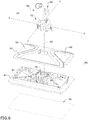
- FIG. 6 is an exploded view of the base 16 of the steam cleaning apparatus 10 of FIG. 1 .
- the base 16 includes a base housing 50, a swivel joint, and a steam distribution nozzle 54, where the base 16 is adapted to mount a steam cleaning pad 56 on the bottom of the base housing 50, and where the base 16 can be mounted to a distal end of the handle tube 14 ( FIG. 1 ), or alternatively, the base 16 can be mounted directly to the steam outlet conduit 36 on the steam unit 12 ( FIG. 4 ).
- the swivel joint 52 couples the base housing 50 to the handle tube 14 or steam unit 12 for movement about at least two orthogonal axes of rotation X, Y.
- the swivel joint 52 can be a universal joint.
- the swivel joint 52 includes a coupler 58 that receives one end of the handle tube 14 ( FIG. 1 ) or one end of the steam unit 12 ( FIG. 4 ), and a foot pedal 60 that is pressed to release the coupler 58 from the handle tube 14 or unit 12, respectively.
- the base housing 50 is generally rectangular and includes an upper cover 62 and a lower cover 64 which are assembled together. Other configurations for the base housing 50 are also possible.
- the steam distribution nozzle 54 is in fluid communication with the steam generator 22 of the steam unit 12 via the handle tube 14.
- the steam distribution nozzle 54 can be provided between the upper and lower covers 62, 64 and is adapted to direct steam through the lower cover 64 to the pad 56, which can substantially cover a lower surface of the lower cover 64.
- Windows 66 for viewing the cleaning pad 56 can be provided in the upper cover 62.
- Flexible tubing or another suitable fluid conduit 68 can deliver steam to the steam distribution nozzle 54 and can, for example, extend through the swivel joint 52 and couple with a fluid connector 69 ( FIG. 14 ) provided inside the coupler 58.
- the fluid connector 69 is configured to receive the steam distribution nozzle 32 of the steam unit 12 or the steam distribution nozzle 74 of the handle tube 14 in order to fluid connect the steam distribution nozzle 54 in the base 16 with the steam delivery system of the steam unit 12.
- the upper and lower cover 64 can together form a cradle 70 for receiving a portion of the swivel joint 52, and the cradle 70 can partially define the first axis X of the swivel joint 52.
- the handle tube 14 can comprise an elongate tubular housing 72 with a first end adapted to be attached to the steam unit 12 and a second end adapted to be attached to the base 16.
- the second end can further comprise a steam distribution nozzle 74 ( FIG. 3 ) that is in fluid communication with a steam conduit 76 ( FIG. 9 ) extending through the tubular housing 72 to the first end.
- Coupling the tubular housing 72 with the steam unit 12 places the steam conduit 76 in fluid communication with the steam delivery system, with the unit nozzle 32 supplying steam to the steam conduit 76, which in turn provides the steam to the handle nozzle 74.
- a detent latch for mounting the handle tube 14 to the steam unit 12 is provided, and may include a pivoting button 78 carried by the handle tube 14 which engages a detent 80 ( FIG. 5 ) provided on the outlet conduit 36 of the steam unit 12.
- the button 78 can be carried by the steam unit 12, with the detent 80 provided in the handle tube 14.
- the handle tube 14 can be used with the steam unit 12 to deliver steam with or without the base 16.
- the steam unit 12/handle tube 14 assembly is pivotally connected to the base 16 for directing the base 16 across the surface to be cleaned.
- the pistol grip 20 on the steam unit 12 can be used for maneuvering the steam mop 10 over a surface to be cleaned.
- the handle tube 14 defines a portion of the steam delivery pathway between the steam generator 22 in the steam unit 12 and the steam distribution nozzle 54 in the base 16.
- the steam mop 10 can deliver steam to the surface from the handle nozzle 74.
- the base 16 in the upright mode, can be indexable between two different orientations relative to the steam unit 12.
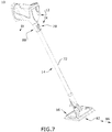
- FIG. 7 shows the base 16 in a wide orientation, with a long side or edge 82 of the generally rectangular base 16 facing forwardly
- FIG. 8 shows the base 16 in a narrow orientation, with a short side or edge 84 of the generally rectangular base 16 facing forwardly.
- the edges 82, 84 can be generally straight sides of the base housing 50 that meet at a common vertex or corner of the base housing 50.
- the base 16 can have an overall rectangular shape as shown herein, with two long edges 82 joined by two short edges 84, but the edges 82, 84 may meet at non-right angles, such as at rounded corners as shown herein, or may have opposing long and short edges 82, 84 of different length.
- Other shapes for the base housing 50 are possible, including those having at least one long side or edge and at least one short side or edge, and including those where the at least one long side or edge and the at least one short side or edge are non-straight but have an overall length that is different.
- the indexing mechanism for flipping the orientation of the base 16 between wide and narrow allows the handle tube 14 and attached base 16 to be rotated 90 degrees so that either the short edge 84 or the long edge 82 of the base 16 can be oriented orthogonal to the direction of travel 86 of the steam mop 10 during operation.
- the direction of travel 86 refers to a direction of movement along an imaginary vertical plane passing through the grip 20 and handle tube 14. This allows the base 16 to be reoriented easily for cleaning areas that are particularly narrow, such as narrow space between toilet and wall or cabinets, for example, in addition to being oriented to clean a wider path in larger, more open areas.
- the swivel joint 52 allows movement about at least two axes of rotation, including front-to-back and side-to-side.
- the indexing mechanism includes a spring-biased control ring or actuator sleeve 88 on the first end of the handle tube 14 that is adapted to be attached to the steam unit 12.
- the sleeve 88 locks the handle tube 14 in one of the two orientations relative to the steam unit 12. Pulling the sleeve 88 in a direction away from the steam unit 12 unlocks the handle tube 14 and allows the handle tube 14 to be rotated (together with the base 16) between the wide and narrow orientations. Releasing the sleeve 88 will re-lock the handle tube 14.
- a wall hanger unit 100 can be provided with the steam mop 10 for storing the steam unit 12, handle tube 14 and base 16.
- the wall hanger unit 100 can attach a wall or other vertical surface, and can have separate receivers 102, 104 for mounting the steam unit 12 and the handle tube 14, respectively.
- the individual receivers 102, 104 allow, for example, the steam unit 12 to be removed from the wall hanger unit 100 while the handle tube 14 remains stored on its receiver 104, and vice versa.
- the steam unit 12 receiver can alternatively mount the entire assembled steam mop 10 as well.
- the base 16 can optionally be mounted on the handle receiver 104 for storage.
- the steam mop 10 can optionally comprise an accessory tool caddy 106 for storing a variety of nozzle attachments or accessory tools that can be attached to the steam distribution nozzle 32 of the steam unit 12 in place of the handle tube 14 or base 16 and/or to the steam distribution nozzle 74 of the handle tube 14 in place of base 16.
- the tool caddy 106 can be carried on the unit housing 18, such as by being be mounted to the bottom 44 of the handheld unit 12, as shown in FIGS. 1-4 , or can be coupled with the wall hanger unit 100, as shown in FIG. 11 .
- the wall hanger unit 100 can have separate receiver 108 for mounting the tool caddy 106.
- the tool caddy 106 can be configured to be interchangeably coupled with the steam unit 12 or the wall hanger unit 100.
- a bottom 110 of the tool caddy 106 can define a substantially flat surface on which the steam unit 12 can rest in an upright position.
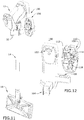
- FIG. 12 Some examples of interchangeable accessory tools that can attach to the steam distribution nozzles 32, 74 are shown in FIG. 12 , and include, but are not limited to a flat grout cleaning brush 112 for cleaning the grout in between tiles, a flat scraping tool nozzle 114 for scraping sticky messes such as gum, sap, tar, etc., an angled nozzle 116 with a narrow outlet opening for concentrating steam in tight or confined spaces, and a round brush 118 for detailing small areas such as a stove, grill, shower, or other bathroom areas.
- the brushes 112, 118 have bristles, while the nozzles 114, 116 do not. Any of these tools 112-118 can be coupled with the steam distribution nozzle 32 of the steam unit 12 or the steam distribution nozzle 74 of the handle tube 14.
- a universal coupling such as a bayonet coupling can be provided on all tools 112-118 so that they can be interchangeably used with the steam mop 10.
- FIG. 13-14 are views of a pivot lock mechanism for the steam mop 10.
- the pivot lock mechanism is configured to prevent side-to-side rotation of the handle tube 14 when the handle tube 14 is in the upright, detented position, which may be an over-vertical position in which the handle tube 14 is tilted slightly forwardly of vertical, relative to the surface on which the base 16 rests.
- the pivot lock mechanism includes a lock bar 120 that engages a detent 122 in the swivel joint 52 in the upright position.
- the detent 122 can, for example, be formed in a cover of the swivel joint 52 which partially defines the axis Y.
- the lock bar 120 can be fixed within the base housing 50, while the detent 122 moves with the coupler 58 of the swivel joint 52.
- the pivot lock mechanism is configured to disengage the swivel joint 52 when the handle tube 14 is reclined to an in-use position, so that the handle tube 14 is free to move side-to-side about axis Y, as well as up and down about axis X.
- the detent 122 moves away from the lock bar 120, freeing swivel joint 52 to move sideways, i.e. side-to-side.
- FIGS. 15-16 show another embodiment of a base 16' and indexing mechanism for the steam mop 10, where like elements are referred by the same reference numeral bearing a prime (') symbol.
- the current embodiment of the indexing mechanism rotates the base 16' only.
- the base 16' includes a base housing 50', a swivel joint 52', and a steam distribution nozzle 54', where the base 16' is adapted to mount a steam cleaning pad 56' ( FIG. 16 ) on the bottom of the base housing 50', and where the base 16' can be mounted to a distal end of the handle tube 14 ( FIG. 1 ), or alternatively, the base 16' can be mounted directly on the steam unit 12 ( FIG. 4 ) as described above for the first embodiment.
- the swivel joint 52' couples the base housing 50' to the handle tube or steam unit 12 for movement about at least two orthogonal axes of rotation. In one embodiment, the swivel joint 52' can be a universal joint.
- the swivel joint 52' can includes a coupler similar to the coupler 58 from the first embodiment that receives one end of the handle tube 14 or one end of the steam unit 12, and a foot pedal similar to the foot pedal 60 from the first embodiment that is pressed to release the coupler from the handle tube 14 or unit 12, respectively.
- the base housing 50' includes an upper cover 62' and a lower cover 64' which are assembled together.
- the base housing 50' is generally rectangular, with a long edge 82' and a short edge 84'. While not shown, windows for viewing the cleaning pad 56' can be provided in the upper cover 62'. Other configurations for the base housing 50' are also possible.
- the steam distribution nozzle 54' can be provided between the upper and lower covers 62', 64' and is adapted to direct steam through the lower cover 64' to the pad 56', which can substantially cover a lower surface of the lower cover 64'.
- Flexible tubing or another suitable fluid conduit can deliver steam to the steam distribution nozzle 54' and can, for example, extend through the swivel joint 52' as described above with respect to the first embodiment of the base 16.
- the indexing mechanism of the base 16' includes a detent latch 130 for selectively locking and unlocking the base 16' relative to the swivel joint 52' so the base housing 50' can be selectively rotated 90 degrees relative to the swivel joint 52', between wide and narrow orientations similar to those shown in FIGS. 7-8 .
- a portion of the base 16' rotates relative to the steam unit 12 or handle tube 14.
- the steam distribution nozzle 54' is always positioned towards the leading edge of the base 16' regardless of whether the base 16' is in the wide or narrow orientation, i.e. whether the leading edge is defined by the long edge 82' or the short edge 84'.
- This configuration differs from the previous embodiment in which the position of the steam distribution nozzle 54 is fixed relative to the base 16, which prevents the nozzle 54 from being positioned towards the leading edge of the base 16 in both wide and narrow orientations.
- the swivel joint 52' is mounted on a turret plate 132, and the base housing 50' rotates around the turret plate 132, and therefore also rotates about the swivel joint 52'.
- the swivel joint 52' and the turret plate 132 can collectively define a turret assembly 134 about which the base housing 50' can selectively be rotated.
- the steam distribution nozzle 54' is provided on the turret assembly 134, such that the base housing 50' is further selectively rotatable relative to the steam distribution nozzle 54'.
- the detent latch 130 selectively locks out rotation of the turret plate 132.
- the detent latch 130 may include a spring-biased retainer 136 carried by the base housing 50' which engages a detent 138 provided on the turret assembly 134, such as on the turret plate 132 in the embodiment shown herein.
- the retainer 136 can be carried by the turret assembly 134, with the detent 138 provided in the base housing 50'.
- a foot pedal 140 can be operably coupled with the retainer 136, and can be depressed to release the retainer 136 from the detent 138, which allows the base housing 16' to rotate about the turret assembly 134. Releasing the foot pedal 140 will re-lock the detent latch 130.
- a spring 142 biases the retainer 136 toward the detent 138.
- the spring 142 can specifically bias the foot pedal 140 upwardly away from the upper cover 62' of the base housing 50'. This biases the retainer 136 downwardly due to a pivotal coupling between the foot pedal 140 and the base housing 50' which is defined by a pivot axle 144 operably coupled between the foot pedal 140 and the retainer 136 and a pivot axle receiver 146 provided on the base housing 50', such as on the lower cover 64'.
- the pivot axle 144, foot pedal 140, and retainer 136 may be molded together as one piece, although other configurations are possible.
- two detents 138 corresponding to the wide and narrow orientations can be provided in the turret assembly 134. As shown herein, the two detents 138 can be provided approximately 90 degrees apart, in correspondence with the wide and narrow orientations.
- the turret plate 132 also mounts the steam distribution nozzle 54'.
- the nozzle 54' can be aligned with a steam outlet opening 148 in the bottom of the base housing 50', such as in the lower cover 64', for dispensing steam to the cleaning pad 56'.
- the steam outlet opening 148 can be elongated or oversized to accommodate for the movement of the base housing 50' relative to the nozzle 54'.
- the steam outlet opening 148 can be arcuate in shape to accommodate for the rotation of the base housing 50' relative to the turret assembly 134.
- FIGS. 17-22 show a third embodiment of an indexing mechanism for the steam mop 10, where like elements are referred by the same reference numeral bearing a double prime (") symbol.
- the third embodiment of the indexing mechanism includes a keyed interface coupling between the handle tube 14" and the steam unit 12" that permits the handle tube 14" to be mounted to the steam unit 12" in any of three positions, so that one long side 82" of the base 16" can face forward, or either short side 84" of the base 16" can face forward.
- the handle tube 14" can be mounted to the steam unit “straight” or the handle tube 14" can be rotated by 90 degrees clockwise or counterclockwise prior to being locked to the steam unit 12".
- the handle tube 14" can comprise an elongate tubular housing 72" with a first end adapted to be attached to the steam unit 12" and a second end adapted to be attached to the base 16".
- the second end can further comprise a steam distribution nozzle (not shown) that is in fluid communication with a steam conduit 76" extending through the tubular housing 72" to the first end. Coupling the tubular housing 72" with the steam unit 12” places the steam conduit 76" in fluid communication with the steam delivery system, with the unit nozzle 32" supplying steam to the steam conduit 76", which in turn provides the steam to the base 16".
- the first end of the handle tube 14" comprises a tube insert 150, which is press fit into the handle tube 14", for selectively connecting and releasing the handle tube 14" to the steam outlet conduit 36" of the steam unit 12"in various positions.
- a detent latch for mounting the handle tube 14" to the steam unit 12" is provided, and may include a release button 152 on the tube insert 150, which can be biased by a spring 154 and has a detent 156 that engages a recessed catch 158 on the steam outlet conduit 36" on the steam unit 12", near the steam distribution nozzle 32".
- the tube insert 150 can further include a steam connector 159 which is received in an end of the steam conduit 76". Upon coupling the tubular housing 72" with the steam unit 12", the steam distribution nozzle 32" is press fit into the tube insert 150 in fluid communication with the steam connector 159.
- a spring-biased control ring or actuator sleeve 160 shown herein as comprising a tubular housing, is mounted to the tube insert 150 via detent hooks 162 on an inner wall of the tubular housing that are received within corresponding recesses 164 on an outer wall of the tube insert 150.
- a spring 165 can bias the sleeve 160 toward the steam unit 12", longitudinally with respect to the handle tube 14".
- an upper rim of the sleeve 160 comprises a lug 166, for engaging a recessed track 168 on the steam outlet conduit 36".
- the track 168 shown herein comprises a T-shape, with an axial track portion 170 joined with a circumferential track portion 172, where the axial track portion 170 extends generally parallel to a longitudinal axis of the elongate tubular housing 72" and the circumferential track portion 172 extends circumferentially about the longitudinal axis of the elongate tubular housing 72".
- a first and second end recess 174, 176 are formed in the steam unit housing 18" at the ends of the circumferential track portion 172, which corresponds to a 90 degree offset around the perimeter of the steam outlet conduit 36" from the axial track portion 170.
- a third end recess 178 is axially aligned with the axial track portion 170.
- the end recesses 174, 176, 178 are sized to receive the lug 166 on the sleeve 160, which locks the handle tube 14" in one of the wide or narrow orientations.
- the rotational position of the handle tube 14" (and thus, the base 16") can be adjusted as follows: To orient the first end of the handle tube 14" at 0 degrees, i.e. in the wide orientation where the long edge 82" of the base 16" faces forward, a user aligns the lug 166 with the track 168 and slides the lug 166 up the axial track portion 170 until the lug 166 is received in the third end recess 178, whereupon the detent 156 on the release button 152 will engage the catch 158 on the steam outlet conduit 36", locking the handle tube 14" to the steam unit 12".
- the user depresses the release button 152, slides the lug 166 out of the end recess 178 and into the circumferential track portion 172 by twisting the tube 14" clockwise or counter-clockwise so the lug 166 slides to either of the first or second end recess 174, 176.
- the user slides the lug 166 into the desired end recess 174, 176 at which point the release button detent 156 engages the catch 158 and locks the handle tube 14" to the steam unit 12" at 90 degrees clockwise or counterclockwise, i.e. to one of the narrow orientations where one of the short edges 84" of the base 16" faces forward.
- rotating the handle tube 14" allows the user to orient either the long edge 82" or either short edge 84" of the base 16" to face forward, depending on the cleaning need.
- FIGS. 23-29 show a fourth embodiment of an indexing mechanism for the steam mop 10, where like elements are referred by the same reference numeral bearing a triple prime ("') symbol.
- the fourth embodiment of the indexing mechanism includes a spring-biased control ring or actuator sleeve on the first end of the handle tube 14"' that is adapted to be attached to the steam unit 12"' and that permits the handle tube 14"' to be rotated (together with the base 16"') between a wide orientation where the long side 82"' of the base 16"' faces forward or a narrow orientation where the short side 84"' of the base 16"' faces forward.
- the handle tube 14"' can comprise an elongate tubular housing 72"' with a first end adapted to be attached to the steam unit 12"' and a second end adapted to be attached to the base 16"'.
- the second end can further comprise a steam distribution nozzle (not shown) that is in fluid communication with a steam conduit 76"' extending through the tubular housing 72"' to the first end. Coupling the tubular housing 72"' with the steam unit 12"' places the steam conduit 76"' in fluid communication with the steam delivery system, with the unit nozzle 32"' supplying steam to the steam conduit 76"', which in turn provides the steam to the base 16"'.
- a detent latch for mounting the handle tube 14"' to the steam unit 12"' can be provided, and may be provided via an adapter housing 180 provided at a first or proximal end of the handle tube 14"'.
- the adapter housing 180 includes a pivoting release button 182 biased by a spring 194 for selectively securing the handle tube 14"' to the steam outlet conduit 36"' on the steam unit 12"'.
- the release button 182 includes a catch 186 for retaining a detent 188 on the steam outlet conduit 36"'. When the release button 182 is depressed, the catch 186 disengages from the detent 188 and the entire handle tube 14"' can be removed from the steam unit 12"'.
- the indexing mechanism allows the handle tube 14"' and base 16"' to be rotated about a longitudinal axis of the tubular housing 72"', relative to the adapter housing 180 and steam unit 12"', which remain stationary.
- the indexing mechanism can include a tube insert 190, a connector 192, a compression spring 194, and an actuator sleeve 196.
- the tube insert 190 comprises a cylindrical body that is configured to retain the connector 192 within the handle tube 14"'.
- the tube insert 190 has detents 198 on an outer portion that are received within detent openings 200 in the tubular housing 72"'.
- the tube insert 190 is configured to be press fit securely into the tubular housing 72".
- An inner flange 202 on a lower portion of the tube insert 190 comprises a proximal flange surface 204 and a distal flange surface 206, the proximal flange surface 204 oriented towards the first end of the handle tube 14"' and the distal flange surface 206 oriented towards the second end of the handle tube 14"'.
- the distal flange surface 204 mates with an outer flange 208 on the connector 192 such that the connector 192 is retained within the tubular housing 72"'.
- a plurality of tabs 210 extend proximally from a rim of the tube insert 190 and are received within slots 212 formed within the sleeve 196. The tabs 210 engage the slots 212 in the sleeve 196, which can selectively induce rotation of the tube insert 190, including the handle tube 14"' fixed thereto when a user twists the sleeve 196 to index the base 16"' relative to the steam unit 12"'.
- the distal end of the adapter housing 180 is secured to a proximal end of the connector 192 by fasteners (not shown) such that the position of the connector 192 relative to the adapter housing 180 and steam unit 12"' is fixed.
- Steam conduits 214, 216 formed within the adapter housing 180 and connector 192, respectively, are fluidly connected to the steam distribution nozzle 32"' on the steam unit 12"' such that a continuous steam flow path extends from the steam outlet conduit 36"' on the steam unit 12"' through the adapter housing 180, connector 192 and through the steam conduit 76"' inside the handle tube 14"' to a steam distribution nozzle (not shown) on the base 16"', but which can be identical to the steam distribution nozzle 54, 54', 54" of any of the previous embodiments.
- the compression spring 194 is mounted around the connector 192 and is sandwiched between the proximal flange surface 204 on the tube insert 190 and a rib (not shown) inside the sleeve 196.
- the compression spring 194 biases the sleeve 196 towards the steam unit 12"'.
- the connector 192 further comprises a pair of U-shaped tracks 218 on an outer portion thereof that receive lugs 220 formed on an inner wall of the sleeve 196.
- Each U-shaped track 218 comprises a pair of axial track portions defining end recesses 222 and a circumferential track portion 224 joining the end recesses 222.
- the lugs 220 on the sleeve 196 are configured to slide through the axial track portions when the sleeve 196 is pushed distally, or away from the steam unit 12", and returns upwardly under the force of the compression spring 194.
- the sleeve 196 When pushed distally, the sleeve 196 can be twist about the longitudinal axis of the handle tube 14"' to slide the lugs 220 through the circumferential track portions 224 to move the lugs 220 into alignment with either end recesses 222 of the tracks 218.
- FIGS. 27-29 are rear perspective views showing the actuator sleeve 196 in various positions during the indexing.
- the adapter housing 180 and steam unit 12"' have been removed for clarity.
- FIG. 27 shows the actuator sleeve 196 in a proximal or home position, as shown in FIG. 25 , where the sleeve 196 is biased by the spring 194 toward the adapter housing 180 and steam unit 12"' and the handle tube 14" is in the wide orientation.
- FIG. 28 shows the actuator sleeve 196 in a retracted position in which the handle tube 14"' is free to index between the wide and narrow orientations.
- FIG. 29 shows the actuator sleeve 196 in a proximal or home position where the handle tube 14" is in the narrow orientation.
- the sleeve 196 is moved to the retracted position. Specifically, the sleeve 196 is pushed distally, or away from the steam unit 12"', compressing the spring 194 and sliding the lugs 220 out of the end recesses 222 of the U-shaped tracks 218, as shown in FIG. 28 .
- the handle tube 14"' can be rotated 90 degrees by twisting the sleeve 196, which slides the lugs 220 to the opposite end of the circumferential track portion 224 of the U-shaped track 218.
- the lugs 220 reach alignment with the other end recess 222, or return portion, of the U-shaped track 218 and slide upwardly to either proximal home position shown in FIG. 27 or 29 under the force of the compression spring 194, which urges the sleeve 196 proximally toward the steam unit 12"'.
- the reverse process is followed to index the handle tube 14"' and base 16"' back to the previous orientation. It is noted that the tabs 210 on the tube insert 190 remain engaged with the slots 212 in the sleeve 196 at all times during indexing, and thus, the handle tube 14"' and the sleeve 196 are interconnected as the sleeve 196 is rotated.
- Another advantage of the present disclosure is that embodiments of the base 16, 16', base 16", base 16"' described above can quickly be indexed between different orientations, depending on the size of the area to be cleaned.
- Another advantage of the present disclosure is that the interchangeable tools and tool caddy provide flexible application to different cleaning tasks in a user's home.
- steam unit 12 shown in the illustrated embodiment offers a more ergonomic and comfortable gripping position, with the pistol-style grip 20 positioned at the rear of the unit.
- aspects of the invention may be used on other types of steam mops and steam cleaners, including non-convertible steam cleaners. Still further, aspects of the invention may also be used on surface cleaning apparatus other than steam cleaners, such as an apparatus configured to deliver liquid rather than steam.
Description
- Surface cleaning apparatus with steam delivery, such as steam mops, are well-known devices for cleaning floor surfaces, such as tile, linoleum, vinyl, laminate, and hardwood floors. Typical steam mops have a reservoir for storing water that is fluidly connected to a selectively engageable pump or valve. The pump or valve outlet is fluidly connected to a steam boiler with a heating element to heat the water. The steam boiler generates steam, which is directed towards the surface to be cleaned through a nozzle or manifold mounted in a foot assembly that engages the floor surface. Steam is typically applied to the backside of a cleaning pad attached to the foot assembly. Steam vapor eventually saturates the entire cleaning pad as the moisture wicks outwardly from the point of steam application. The damp pad is wiped across the floor surface to remove dirt, dust, and debris present on the floor surface.
EP 0 616 790 A2 discloses a steam cleaner having a steam unit within a housing, a device handle, and a base coupled with the device handle via an articulated connection. The tube-like device handle is provided at one end with a handle grip and the other end with a working attachment or base, via the hinge connection with a working attachment.
GB 2 522 668 A - According to one aspect of the invention, a steam cleaning apparatus includes a steam unit, an elongated handle tube coupled with an outlet of the steam unit, a base coupled with the handle tube and adapted to move over a surface to be cleaned in a direction of travel, the base having a base housing with a long edge and a short edge that is shorter than the long edge, and an indexing mechanism configured to move at least the base housing between a wide orientation where the long edge of the base housing is orthogonal to the direction of travel and a narrow orientation where the short edge of the base housing is orthogonal to the direction of travel.
- The invention will now be described with respect to the drawings in which:
-
FIG. 1 is a perspective view of a steam cleaning apparatus in the form of a convertible steam mop according to one embodiment of the invention, with the steam mop in an upright or mopping mode of operation; -
FIG. 2 is a perspective view of the steam cleaning apparatus ofFIG. 1 in a handheld mode of operation; -
FIG. 3 is a perspective view of the steam cleaning apparatus ofFIG. 1 in a remote cleaning mode of operation; -
FIG. 4 is a perspective view of the steam cleaning apparatus ofFIG. 1 in a handheld accessory mode of operation; -
FIG. 5 is a cross-sectional view through line V-V ofFIG. 4 , showing a steam unit of the steam cleaning apparatus ofFIG. 1 ; -
FIG. 6 is an exploded view of a base of the steam cleaning apparatus ofFIG. 1 ; -
FIG. 7 is a perspective view of the steam cleaning apparatus ofFIG. 1 , with the base in a wide orientation; -
FIG. 8 is a perspective view of the steam cleaning apparatus ofFIG. 1 , with the base in a narrow orientation; -
FIG. 9 is a section view through line IX-IX ofFIG. 7 , showing a coupling between the steam unit and the handle tube, and the operation of an indexing mechanism for moving the base between the wide and narrow orientations; -
FIG. 10 is a close-up view of the coupling between the steam unit and the handle tube, showing the operation of the indexing mechanism for moving the base between the wide and narrow orientations; -
FIG. 11 is a perspective view of the steam cleaning apparatus ofFIG. 1 assembled with a wall hanger unit; -
FIG. 12 is a perspective view of the wall hanger unit ofFIG. 11 , with a tool caddy exploded from the wall hanger unit; -
FIG. 13 is a close-up view of a swivel joint between the handle tube and the base, showing a pivot lock mechanism in a locked position; -
FIG. 14 is a sectional view through line XIV-XIV ofFIG. 13 , showing the swivel joint between the handle tube and the base, showing the pivot lock mechanism in a locked position; -
FIG. 15 is a perspective view of a base for a steam cleaning apparatus having an indexing mechanism according to a second embodiment of the invention; -
FIG. 16 is an exploded view of a base ofFIG. 15 ; -
FIG. 17 is a perspective view of the steam cleaning apparatus with an indexing mechanism according to a third embodiment of the invention, with the base in a wide orientation; -
FIG. 18 is a perspective view of the steam cleaning apparatus ofFIG. 17 , with the base in a first narrow orientation; -
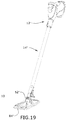
FIG. 19 is a perspective view of the steam cleaning apparatus ofFIG. 17 , with the base in a second narrow orientation; -
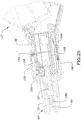
FIG. 20 is a section view through line XX-XX ofFIG. 17 , showing a coupling between the steam unit and the handle tube; -
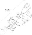
FIG. 21 is a top perspective exploded view of the coupling between the steam unit and the handle tube for the steam cleaning apparatus ofFIG. 17 ; -
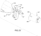
FIG. 22 is a bottom perspective exploded view of the coupling between the steam unit and the handle tube for the steam cleaning apparatus ofFIG. 17 ; -
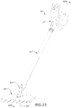
FIG. 23 is a perspective view of the steam cleaning apparatus with an indexing mechanism according to a fourth embodiment of the invention, with the base in a wide orientation; -
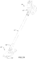
FIG. 24 is a perspective view of the steam cleaning apparatus ofFIG. 23 , with the base in a narrow orientation; -
FIG. 25 is a section view through line XXV-XXV ofFIG. 23 , showing a coupling between the steam unit and the handle tube; -
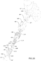
FIG. 26 is a top perspective exploded view of the coupling between the steam unit and the handle tube for the steam cleaning apparatus ofFIG. 23 ; -
FIGS. 27-29 are rear perspective views of the coupling between the steam unit and the handle tube for the steam cleaning apparatus ofFIG. 23 showing the operation of the indexing mechanism. - The invention relates to a surface cleaning apparatus such as a steam cleaning apparatus or steam mop, for steam cleaning surfaces. More specifically, the invention relates to a steam mop that can be converted into different use configurations, including hand-held use.
-
FIG. 1 is a perspective view of asteam cleaning apparatus 10 according to one embodiment of the invention. Thesteam cleaning apparatus 10 of the illustrated embodiment may alternatively be referred to herein as a steam mop, and includes asteam unit 12, adetachable handle tube 14 and abase 16 adapted to move over a surface to be cleaned. Thesteam mop 10 can generate and deliver steam to a surface to be cleaned, including floor surfaces, such as tile, linoleum, vinyl, laminate, and hardwood floors, and other hard surfaces such as tiles and countertops. Thesteam mop 10 is convertible between different modes of operation to efficiently clean different surface types and hard-to-reach areas. - For purposes of description related to the figures, the terms "upper," "lower," "right," "left," "rear," "front," "vertical," "horizontal," "inner," "outer," and derivatives thereof shall relate to the invention as oriented in
FIG. 1 from the perspective of a user behind thesteam unit 12 and holding thesteam unit 12 by its grip, which defines a rear of thesteam unit 12 or steam cleaning apparatus. However, it is to be understood that the invention may assume various alternative orientations, except where expressly specified to the contrary. - The
steam unit 12 can comprise a modular,handheld steam unit 12 that can be used independently of thehandle tube 14 andbase 16 to clean a surface. Thus, thehandle tube 14 andbase 16 are removable or detachable from thesteam unit 12. Thesteam mop 10 is convertible between at least two different modes of operation, including an upright or mopping mode of operation shown inFIG. 1 , in which thehandle tube 14 andbase 16 are attached to thesteam unit 12, and a handheld mode of operation shown inFIG. 2 , in which thehandle tube 14 andbase 16 are detached from thesteam unit 12. The upright or mopping mode may be useful for cleaning floor surfaces, such as tile, linoleum, vinyl, laminate, and hardwood floors, while the handheld mode may be useful for cleaning other hard surfaces such as tiles and countertops. - The
steam mop 10 can further be provided with other modes of operation, such as a remote cleaning mode of operation, shown inFIG. 3 , in which thehandle tube 14 is attached to thesteam unit 12 and thebase 16 is removed, which allows thesteam mop 10 to clean remote or hard to reach areas. Another mode of operation is a handheld accessory mode of operation, one example of which is shown inFIG. 4 , in which thehandle tube 14 is detached from thesteam unit 12, and a cleaning accessory tool is attached in its place. For example, thebase 16 itself can be directly attached to thesteam unit 12. Other examples of accessory tools that can be used in the handheld accessory mode are shown inFIG. 12 . -
FIG. 5 is a cross-sectional view through thesteam unit 12 of thesteam cleaning apparatus 10 ofFIG. 1 . Thesteam unit 12 can comprise ahousing 18 with a pistol-style grip 20 and which carries a steam delivery system for generating steam and delivering the steam to a surface to be cleaned. The steam delivery system can include asteam generator 22 in the form of a heater for heating liquid to at least 100 °C to generate steam, asupply tank 24 in fluid communication with aninlet 26 of thesteam generator 22, apump 28 which pressurizes the delivery system to supply liquid from thetank 24 to thesteam generator 22, anactuator 30 for thepump 28 to deliver liquid on demand to thesteam generator 22, and asteam distribution nozzle 32 in fluid communication with anoutlet 34 of thesteam generator 22 for delivering steam to a surface to be cleaned directly, or indirectly via thehandle tube 14,base 16, or another cleaning tool as described in further detail below. Thesteam distribution nozzle 32 can be provided on asteam outlet conduit 36 protruding from thesteam unit housing 18. Thesteam outlet conduit 36 can further mount various attachments, including thehandle tube 14 and/or one or more cleaning tools described herein. Flexible tubing or other suitablefluid conduits steam generator inlet 26 and thesteam generator outlet 34 with thesteam distribution nozzle 32, respectively. - The liquid in the
supply tank 24 can comprise one or more of any suitable cleaning liquids, including, but not limited to, water or mixtures containing water. Thesupply tank 24 can be removable from thehousing 18 for refilling thetank 24 with liquid, or can be refilled when on thehousing 18. - The
steam distribution nozzle 32 can include at least onenozzle outlet 42 on theunit housing 18 for delivering steam to a surface to be cleaned. Thesteam distribution nozzle 32 can be in an opposing relationship to thepistol grip 20, with thesteam distribution nozzle 32 on a forward end of theunit housing 18 and the pistol grip 20 a rearward end of theunit housing 18. A bottom 44 of theunit housing 18 can define a substantially flat surface on which theunit 12 can rest in an upright position. - A
power cord 46, which emerges from the interior of thehousing 18 through acord aperture 48, can be used to provide power to electrical components of thesteam mop 10 from a source of power, such as a home power supply, upon actuation of theactuator 30. Alternatively, thesteam mop 10 can be powered by a portable power supply, such as a battery. -
FIG. 6 is an exploded view of thebase 16 of thesteam cleaning apparatus 10 ofFIG. 1 . Thebase 16 includes abase housing 50, a swivel joint, and asteam distribution nozzle 54, where thebase 16 is adapted to mount asteam cleaning pad 56 on the bottom of thebase housing 50, and where the base 16 can be mounted to a distal end of the handle tube 14 (FIG. 1 ), or alternatively, thebase 16 can be mounted directly to thesteam outlet conduit 36 on the steam unit 12 (FIG. 4 ). The swivel joint 52 couples thebase housing 50 to thehandle tube 14 orsteam unit 12 for movement about at least two orthogonal axes of rotation X, Y. In one embodiment, the swivel joint 52 can be a universal joint. The swivel joint 52 includes acoupler 58 that receives one end of the handle tube 14 (FIG. 1 ) or one end of the steam unit 12 (FIG. 4 ), and afoot pedal 60 that is pressed to release thecoupler 58 from thehandle tube 14 orunit 12, respectively. - As shown herein, the
base housing 50 is generally rectangular and includes anupper cover 62 and alower cover 64 which are assembled together. Other configurations for thebase housing 50 are also possible. - The
steam distribution nozzle 54 is in fluid communication with thesteam generator 22 of thesteam unit 12 via thehandle tube 14. Thesteam distribution nozzle 54 can be provided between the upper andlower covers lower cover 64 to thepad 56, which can substantially cover a lower surface of thelower cover 64.Windows 66 for viewing thecleaning pad 56 can be provided in theupper cover 62. Flexible tubing or anothersuitable fluid conduit 68 can deliver steam to thesteam distribution nozzle 54 and can, for example, extend through the swivel joint 52 and couple with a fluid connector 69 (FIG. 14 ) provided inside thecoupler 58. Thefluid connector 69 is configured to receive thesteam distribution nozzle 32 of thesteam unit 12 or thesteam distribution nozzle 74 of thehandle tube 14 in order to fluid connect thesteam distribution nozzle 54 in the base 16 with the steam delivery system of thesteam unit 12. The upper andlower cover 64 can together form acradle 70 for receiving a portion of the swivel joint 52, and thecradle 70 can partially define the first axis X of the swivel joint 52. - Referring to
FIG. 7 , thehandle tube 14 can comprise an elongatetubular housing 72 with a first end adapted to be attached to thesteam unit 12 and a second end adapted to be attached to thebase 16. The second end can further comprise a steam distribution nozzle 74 (FIG. 3 ) that is in fluid communication with a steam conduit 76 (FIG. 9 ) extending through thetubular housing 72 to the first end. Coupling thetubular housing 72 with thesteam unit 12 places thesteam conduit 76 in fluid communication with the steam delivery system, with theunit nozzle 32 supplying steam to thesteam conduit 76, which in turn provides the steam to thehandle nozzle 74. - A detent latch for mounting the
handle tube 14 to thesteam unit 12 is provided, and may include apivoting button 78 carried by thehandle tube 14 which engages a detent 80 (FIG. 5 ) provided on theoutlet conduit 36 of thesteam unit 12. Alternatively, thebutton 78 can be carried by thesteam unit 12, with thedetent 80 provided in thehandle tube 14. - The
handle tube 14 can be used with thesteam unit 12 to deliver steam with or without thebase 16. In the upright mode, shown inFIG. 1 , thesteam unit 12/handle tube 14 assembly is pivotally connected to thebase 16 for directing thebase 16 across the surface to be cleaned. Thepistol grip 20 on thesteam unit 12 can be used for maneuvering thesteam mop 10 over a surface to be cleaned. When connected between thesteam unit 12 and thebase 16, thehandle tube 14 defines a portion of the steam delivery pathway between thesteam generator 22 in thesteam unit 12 and thesteam distribution nozzle 54 in thebase 16. When used without thebase 16, as shown inFIG. 3 , thesteam mop 10 can deliver steam to the surface from thehandle nozzle 74. - As shown in
FIGS. 7-10 , in the upright mode, thebase 16 can be indexable between two different orientations relative to thesteam unit 12.FIG. 7 shows the base 16 in a wide orientation, with a long side or edge 82 of the generallyrectangular base 16 facing forwardly, andFIG. 8 shows the base 16 in a narrow orientation, with a short side or edge 84 of the generallyrectangular base 16 facing forwardly. For a generallyrectangular base 16 as shown herein, theedges base housing 50 that meet at a common vertex or corner of thebase housing 50. By "generally rectangular", thebase 16 can have an overall rectangular shape as shown herein, with twolong edges 82 joined by twoshort edges 84, but theedges short edges base housing 50 are possible, including those having at least one long side or edge and at least one short side or edge, and including those where the at least one long side or edge and the at least one short side or edge are non-straight but have an overall length that is different. - The indexing mechanism for flipping the orientation of the base 16 between wide and narrow allows the
handle tube 14 and attachedbase 16 to be rotated 90 degrees so that either theshort edge 84 or thelong edge 82 of the base 16 can be oriented orthogonal to the direction oftravel 86 of thesteam mop 10 during operation. The direction oftravel 86 refers to a direction of movement along an imaginary vertical plane passing through thegrip 20 and handletube 14. This allows the base 16 to be reoriented easily for cleaning areas that are particularly narrow, such as narrow space between toilet and wall or cabinets, for example, in addition to being oriented to clean a wider path in larger, more open areas. In both orientations, the swivel joint 52 allows movement about at least two axes of rotation, including front-to-back and side-to-side. - In one example illustrated in the figures, the indexing mechanism includes a spring-biased control ring or
actuator sleeve 88 on the first end of thehandle tube 14 that is adapted to be attached to thesteam unit 12. Thesleeve 88 locks thehandle tube 14 in one of the two orientations relative to thesteam unit 12. Pulling thesleeve 88 in a direction away from thesteam unit 12 unlocks thehandle tube 14 and allows thehandle tube 14 to be rotated (together with the base 16) between the wide and narrow orientations. Releasing thesleeve 88 will re-lock thehandle tube 14. - Referring to
FIGS. 11-12 , awall hanger unit 100 can be provided with thesteam mop 10 for storing thesteam unit 12, handletube 14 andbase 16. Thewall hanger unit 100 can attach a wall or other vertical surface, and can haveseparate receivers steam unit 12 and thehandle tube 14, respectively. Theindividual receivers steam unit 12 to be removed from thewall hanger unit 100 while thehandle tube 14 remains stored on itsreceiver 104, and vice versa. However, thesteam unit 12 receiver can alternatively mount the entire assembledsteam mop 10 as well. Also, if thesteam unit 12 and handletube 14 are in use without thebase 16, thebase 16 can optionally be mounted on thehandle receiver 104 for storage. - The
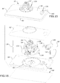
steam mop 10 can optionally comprise anaccessory tool caddy 106 for storing a variety of nozzle attachments or accessory tools that can be attached to thesteam distribution nozzle 32 of thesteam unit 12 in place of thehandle tube 14 orbase 16 and/or to thesteam distribution nozzle 74 of thehandle tube 14 in place ofbase 16. Thetool caddy 106 can be carried on theunit housing 18, such as by being be mounted to the bottom 44 of thehandheld unit 12, as shown inFIGS. 1-4 , or can be coupled with thewall hanger unit 100, as shown inFIG. 11 . Thewall hanger unit 100 can haveseparate receiver 108 for mounting thetool caddy 106. Thetool caddy 106 can be configured to be interchangeably coupled with thesteam unit 12 or thewall hanger unit 100. When attached to thesteam unit 12, abottom 110 of thetool caddy 106 can define a substantially flat surface on which thesteam unit 12 can rest in an upright position. - Some examples of interchangeable accessory tools that can attach to the
steam distribution nozzles FIG. 12 , and include, but are not limited to a flatgrout cleaning brush 112 for cleaning the grout in between tiles, a flatscraping tool nozzle 114 for scraping sticky messes such as gum, sap, tar, etc., an angled nozzle 116 with a narrow outlet opening for concentrating steam in tight or confined spaces, and around brush 118 for detailing small areas such as a stove, grill, shower, or other bathroom areas. Thebrushes nozzles 114, 116 do not. Any of these tools 112-118 can be coupled with thesteam distribution nozzle 32 of thesteam unit 12 or thesteam distribution nozzle 74 of thehandle tube 14. A universal coupling such as a bayonet coupling can be provided on all tools 112-118 so that they can be interchangeably used with thesteam mop 10. -
FIG. 13-14 are views of a pivot lock mechanism for thesteam mop 10. The pivot lock mechanism is configured to prevent side-to-side rotation of thehandle tube 14 when thehandle tube 14 is in the upright, detented position, which may be an over-vertical position in which thehandle tube 14 is tilted slightly forwardly of vertical, relative to the surface on which thebase 16 rests. The pivot lock mechanism includes alock bar 120 that engages adetent 122 in the swivel joint 52 in the upright position. Thedetent 122 can, for example, be formed in a cover of the swivel joint 52 which partially defines the axis Y. Thelock bar 120 can be fixed within thebase housing 50, while thedetent 122 moves with thecoupler 58 of the swivel joint 52. The pivot lock mechanism is configured to disengage the swivel joint 52 when thehandle tube 14 is reclined to an in-use position, so that thehandle tube 14 is free to move side-to-side about axis Y, as well as up and down about axis X. By reclining thehandle tube 14, thedetent 122 moves away from thelock bar 120, freeing swivel joint 52 to move sideways, i.e. side-to-side. -
FIGS. 15-16 show another embodiment of a base 16' and indexing mechanism for thesteam mop 10, where like elements are referred by the same reference numeral bearing a prime (') symbol. Instead of rotating theentire handle tube 14 like in the previous embodiment (seeFIGS. 7-8 ), the current embodiment of the indexing mechanism rotates the base 16' only. - The base 16' includes a base housing 50', a swivel joint 52', and a steam distribution nozzle 54', where the base 16' is adapted to mount a steam cleaning pad 56' (
FIG. 16 ) on the bottom of the base housing 50', and where the base 16' can be mounted to a distal end of the handle tube 14 (FIG. 1 ), or alternatively, the base 16' can be mounted directly on the steam unit 12 (FIG. 4 ) as described above for the first embodiment. The swivel joint 52' couples the base housing 50' to the handle tube orsteam unit 12 for movement about at least two orthogonal axes of rotation. In one embodiment, the swivel joint 52' can be a universal joint. While not shown, the swivel joint 52' can includes a coupler similar to thecoupler 58 from the first embodiment that receives one end of thehandle tube 14 or one end of thesteam unit 12, and a foot pedal similar to thefoot pedal 60 from the first embodiment that is pressed to release the coupler from thehandle tube 14 orunit 12, respectively. - As shown herein, the base housing 50' includes an upper cover 62' and a
lower cover 64' which are assembled together. The base housing 50' is generally rectangular, with a long edge 82' and a short edge 84'. While not shown, windows for viewing the cleaning pad 56' can be provided in the upper cover 62'. Other configurations for the base housing 50' are also possible. - The steam distribution nozzle 54' can be provided between the upper and
lower covers 62', 64' and is adapted to direct steam through thelower cover 64' to the pad 56', which can substantially cover a lower surface of thelower cover 64'. Flexible tubing or another suitable fluid conduit (not shown) can deliver steam to the steam distribution nozzle 54' and can, for example, extend through the swivel joint 52' as described above with respect to the first embodiment of thebase 16. - The indexing mechanism of the base 16' includes a
detent latch 130 for selectively locking and unlocking the base 16' relative to the swivel joint 52' so the base housing 50' can be selectively rotated 90 degrees relative to the swivel joint 52', between wide and narrow orientations similar to those shown inFIGS. 7-8 . UnlikeFIGS. 7-8 however, at least a portion of the base 16' rotates relative to thesteam unit 12 or handletube 14. Thus, the steam distribution nozzle 54' is always positioned towards the leading edge of the base 16' regardless of whether the base 16' is in the wide or narrow orientation, i.e. whether the leading edge is defined by the long edge 82' or the short edge 84'. This configuration differs from the previous embodiment in which the position of thesteam distribution nozzle 54 is fixed relative to thebase 16, which prevents thenozzle 54 from being positioned towards the leading edge of the base 16 in both wide and narrow orientations. - The swivel joint 52' is mounted on a
turret plate 132, and the base housing 50' rotates around theturret plate 132, and therefore also rotates about the swivel joint 52'. The swivel joint 52' and theturret plate 132 can collectively define aturret assembly 134 about which the base housing 50' can selectively be rotated. The steam distribution nozzle 54' is provided on theturret assembly 134, such that the base housing 50' is further selectively rotatable relative to the steam distribution nozzle 54'. - The
detent latch 130 selectively locks out rotation of theturret plate 132. Thedetent latch 130 may include a spring-biasedretainer 136 carried by the base housing 50' which engages adetent 138 provided on theturret assembly 134, such as on theturret plate 132 in the embodiment shown herein. Alternatively, theretainer 136 can be carried by theturret assembly 134, with thedetent 138 provided in the base housing 50'. Afoot pedal 140 can be operably coupled with theretainer 136, and can be depressed to release theretainer 136 from thedetent 138, which allows the base housing 16' to rotate about theturret assembly 134. Releasing thefoot pedal 140 will re-lock thedetent latch 130. - A
spring 142 biases theretainer 136 toward thedetent 138. As shown herein, thespring 142 can specifically bias thefoot pedal 140 upwardly away from the upper cover 62' of the base housing 50'. This biases theretainer 136 downwardly due to a pivotal coupling between thefoot pedal 140 and the base housing 50' which is defined by apivot axle 144 operably coupled between thefoot pedal 140 and theretainer 136 and apivot axle receiver 146 provided on the base housing 50', such as on thelower cover 64'. As shown here, thepivot axle 144,foot pedal 140, andretainer 136 may be molded together as one piece, although other configurations are possible. - It is noted that two
detents 138 corresponding to the wide and narrow orientations can be provided in theturret assembly 134. As shown herein, the twodetents 138 can be provided approximately 90 degrees apart, in correspondence with the wide and narrow orientations. - In the embodiment shown herein, the
turret plate 132 also mounts the steam distribution nozzle 54'. The nozzle 54' can be aligned with a steam outlet opening 148 in the bottom of the base housing 50', such as in thelower cover 64', for dispensing steam to the cleaning pad 56'. The steam outlet opening 148 can be elongated or oversized to accommodate for the movement of the base housing 50' relative to the nozzle 54'. As shown herein, the steam outlet opening 148 can be arcuate in shape to accommodate for the rotation of the base housing 50' relative to theturret assembly 134. -
FIGS. 17-22 show a third embodiment of an indexing mechanism for thesteam mop 10, where like elements are referred by the same reference numeral bearing a double prime (") symbol. The third embodiment of the indexing mechanism includes a keyed interface coupling between thehandle tube 14" and thesteam unit 12" that permits thehandle tube 14" to be mounted to thesteam unit 12" in any of three positions, so that onelong side 82" of the base 16" can face forward, or eithershort side 84" of the base 16" can face forward. Thehandle tube 14" can be mounted to the steam unit "straight" or thehandle tube 14" can be rotated by 90 degrees clockwise or counterclockwise prior to being locked to thesteam unit 12". - Referring to
FIG. 20 , thehandle tube 14" can comprise an elongatetubular housing 72" with a first end adapted to be attached to thesteam unit 12" and a second end adapted to be attached to the base 16". The second end can further comprise a steam distribution nozzle (not shown) that is in fluid communication with asteam conduit 76" extending through thetubular housing 72" to the first end. Coupling thetubular housing 72" with thesteam unit 12" places thesteam conduit 76" in fluid communication with the steam delivery system, with theunit nozzle 32" supplying steam to thesteam conduit 76", which in turn provides the steam to the base 16". - The first end of the
handle tube 14" comprises atube insert 150, which is press fit into thehandle tube 14", for selectively connecting and releasing thehandle tube 14" to thesteam outlet conduit 36" of thesteam unit 12"in various positions. A detent latch for mounting thehandle tube 14" to thesteam unit 12" is provided, and may include arelease button 152 on thetube insert 150, which can be biased by aspring 154 and has adetent 156 that engages a recessedcatch 158 on thesteam outlet conduit 36" on thesteam unit 12", near thesteam distribution nozzle 32". Thetube insert 150 can further include asteam connector 159 which is received in an end of thesteam conduit 76". Upon coupling thetubular housing 72" with thesteam unit 12", thesteam distribution nozzle 32" is press fit into thetube insert 150 in fluid communication with thesteam connector 159. - A spring-biased control ring or
actuator sleeve 160, shown herein as comprising a tubular housing, is mounted to thetube insert 150 via detent hooks 162 on an inner wall of the tubular housing that are received within correspondingrecesses 164 on an outer wall of thetube insert 150. Aspring 165 can bias thesleeve 160 toward thesteam unit 12", longitudinally with respect to thehandle tube 14". - Referring additionally to
FIG. 22 , an upper rim of thesleeve 160 comprises alug 166, for engaging a recessedtrack 168 on thesteam outlet conduit 36". Thetrack 168 shown herein comprises a T-shape, with anaxial track portion 170 joined with acircumferential track portion 172, where theaxial track portion 170 extends generally parallel to a longitudinal axis of the elongatetubular housing 72" and thecircumferential track portion 172 extends circumferentially about the longitudinal axis of the elongatetubular housing 72". A first andsecond end recess steam unit housing 18" at the ends of thecircumferential track portion 172, which corresponds to a 90 degree offset around the perimeter of thesteam outlet conduit 36" from theaxial track portion 170. Athird end recess 178 is axially aligned with theaxial track portion 170. The end recesses 174, 176, 178 are sized to receive thelug 166 on thesleeve 160, which locks thehandle tube 14" in one of the wide or narrow orientations. - In use, the rotational position of the
handle tube 14" (and thus, the base 16") can be adjusted as follows: To orient the first end of thehandle tube 14" at 0 degrees, i.e. in the wide orientation where thelong edge 82" of the base 16" faces forward, a user aligns thelug 166 with thetrack 168 and slides thelug 166 up theaxial track portion 170 until thelug 166 is received in thethird end recess 178, whereupon thedetent 156 on therelease button 152 will engage thecatch 158 on thesteam outlet conduit 36", locking thehandle tube 14" to thesteam unit 12". To rotate thehandle tube 14", the user depresses therelease button 152, slides thelug 166 out of theend recess 178 and into thecircumferential track portion 172 by twisting thetube 14" clockwise or counter-clockwise so thelug 166 slides to either of the first orsecond end recess lug 166 into the desiredend recess release button detent 156 engages thecatch 158 and locks thehandle tube 14" to thesteam unit 12" at 90 degrees clockwise or counterclockwise, i.e. to one of the narrow orientations where one of theshort edges 84" of the base 16" faces forward. As shown inFIGS. 17-19 , rotating thehandle tube 14" allows the user to orient either thelong edge 82" or eithershort edge 84" of the base 16" to face forward, depending on the cleaning need. -
FIGS. 23-29 show a fourth embodiment of an indexing mechanism for thesteam mop 10, where like elements are referred by the same reference numeral bearing a triple prime ("') symbol. The fourth embodiment of the indexing mechanism includes a spring-biased control ring or actuator sleeve on the first end of thehandle tube 14"' that is adapted to be attached to thesteam unit 12"' and that permits thehandle tube 14"' to be rotated (together with the base 16"') between a wide orientation where thelong side 82"' of the base 16"' faces forward or a narrow orientation where theshort side 84"' of the base 16"' faces forward. - Referring to
FIG. 25 , thehandle tube 14"' can comprise an elongatetubular housing 72"' with a first end adapted to be attached to thesteam unit 12"' and a second end adapted to be attached to the base 16"'. The second end can further comprise a steam distribution nozzle (not shown) that is in fluid communication with asteam conduit 76"' extending through thetubular housing 72"' to the first end. Coupling thetubular housing 72"' with thesteam unit 12"' places thesteam conduit 76"' in fluid communication with the steam delivery system, with theunit nozzle 32"' supplying steam to thesteam conduit 76"', which in turn provides the steam to the base 16"'. - A detent latch for mounting the
handle tube 14"' to thesteam unit 12"' can be provided, and may be provided via anadapter housing 180 provided at a first or proximal end of thehandle tube 14"'. Theadapter housing 180 includes a pivotingrelease button 182 biased by aspring 194 for selectively securing thehandle tube 14"' to thesteam outlet conduit 36"' on thesteam unit 12"'. Therelease button 182 includes acatch 186 for retaining adetent 188 on thesteam outlet conduit 36"'. When therelease button 182 is depressed, thecatch 186 disengages from thedetent 188 and theentire handle tube 14"' can be removed from thesteam unit 12"'. - The indexing mechanism allows the
handle tube 14"' andbase 16"' to be rotated about a longitudinal axis of thetubular housing 72"', relative to theadapter housing 180 andsteam unit 12"', which remain stationary. In one embodiment, the indexing mechanism can include atube insert 190, aconnector 192, acompression spring 194, and anactuator sleeve 196. - The
tube insert 190 comprises a cylindrical body that is configured to retain theconnector 192 within thehandle tube 14"'. Thetube insert 190 hasdetents 198 on an outer portion that are received withindetent openings 200 in thetubular housing 72"'. Thetube insert 190 is configured to be press fit securely into thetubular housing 72". Aninner flange 202 on a lower portion of thetube insert 190 comprises aproximal flange surface 204 and adistal flange surface 206, theproximal flange surface 204 oriented towards the first end of thehandle tube 14"' and thedistal flange surface 206 oriented towards the second end of thehandle tube 14"'. Thedistal flange surface 204 mates with anouter flange 208 on theconnector 192 such that theconnector 192 is retained within thetubular housing 72"'. A plurality oftabs 210 extend proximally from a rim of thetube insert 190 and are received withinslots 212 formed within thesleeve 196. Thetabs 210 engage theslots 212 in thesleeve 196, which can selectively induce rotation of thetube insert 190, including thehandle tube 14"' fixed thereto when a user twists thesleeve 196 to index the base 16"' relative to thesteam unit 12"'. - The distal end of the
adapter housing 180 is secured to a proximal end of theconnector 192 by fasteners (not shown) such that the position of theconnector 192 relative to theadapter housing 180 andsteam unit 12"' is fixed.Steam conduits adapter housing 180 andconnector 192, respectively, are fluidly connected to thesteam distribution nozzle 32"' on thesteam unit 12"' such that a continuous steam flow path extends from thesteam outlet conduit 36"' on thesteam unit 12"' through theadapter housing 180,connector 192 and through thesteam conduit 76"' inside thehandle tube 14"' to a steam distribution nozzle (not shown) on the base 16"', but which can be identical to thesteam distribution nozzle - The
compression spring 194 is mounted around theconnector 192 and is sandwiched between theproximal flange surface 204 on thetube insert 190 and a rib (not shown) inside thesleeve 196. Thecompression spring 194 biases thesleeve 196 towards thesteam unit 12"'. - The
connector 192 further comprises a pair ofU-shaped tracks 218 on an outer portion thereof that receive lugs 220 formed on an inner wall of thesleeve 196. EachU-shaped track 218 comprises a pair of axial track portions defining end recesses 222 and acircumferential track portion 224 joining the end recesses 222. Thelugs 220 on thesleeve 196 are configured to slide through the axial track portions when thesleeve 196 is pushed distally, or away from thesteam unit 12", and returns upwardly under the force of thecompression spring 194. When pushed distally, thesleeve 196 can be twist about the longitudinal axis of thehandle tube 14"' to slide thelugs 220 through thecircumferential track portions 224 to move thelugs 220 into alignment with either end recesses 222 of thetracks 218. -
FIGS. 27-29 are rear perspective views showing theactuator sleeve 196 in various positions during the indexing. InFIGS. 27-29 , theadapter housing 180 andsteam unit 12"' have been removed for clarity.FIG. 27 shows theactuator sleeve 196 in a proximal or home position, as shown inFIG. 25 , where thesleeve 196 is biased by thespring 194 toward theadapter housing 180 andsteam unit 12"' and thehandle tube 14" is in the wide orientation.FIG. 28 shows theactuator sleeve 196 in a retracted position in which thehandle tube 14"' is free to index between the wide and narrow orientations.FIG. 29 shows theactuator sleeve 196 in a proximal or home position where thehandle tube 14" is in the narrow orientation. - Referring to
FIGS. 25-29 , to index thehandle tube 14"', and therefore the base 16"', thesleeve 196 is moved to the retracted position. Specifically, thesleeve 196 is pushed distally, or away from thesteam unit 12"', compressing thespring 194 and sliding thelugs 220 out of the end recesses 222 of theU-shaped tracks 218, as shown inFIG. 28 . Next, thehandle tube 14"' can be rotated 90 degrees by twisting thesleeve 196, which slides thelugs 220 to the opposite end of thecircumferential track portion 224 of theU-shaped track 218. At 90 degrees rotation, thelugs 220 reach alignment with theother end recess 222, or return portion, of theU-shaped track 218 and slide upwardly to either proximal home position shown inFIG. 27 or 29 under the force of thecompression spring 194, which urges thesleeve 196 proximally toward thesteam unit 12"'. The reverse process is followed to index thehandle tube 14"' andbase 16"' back to the previous orientation. It is noted that thetabs 210 on thetube insert 190 remain engaged with theslots 212 in thesleeve 196 at all times during indexing, and thus, thehandle tube 14"' and thesleeve 196 are interconnected as thesleeve 196 is rotated. - There are several advantages of the present disclosure arising from the various features of the apparatuses described herein. For example, the embodiments of the invention described above allow for quickly converting the
steam mop 10 between different modes of operation. - Another advantage of the present disclosure is that embodiments of the
base 16, 16',base 16",base 16"' described above can quickly be indexed between different orientations, depending on the size of the area to be cleaned. - Another advantage of the present disclosure is that the interchangeable tools and tool caddy provide flexible application to different cleaning tasks in a user's home.
- Yet another advantage of the present disclosure is that the
steam unit 12 shown in the illustrated embodiment offers a more ergonomic and comfortable gripping position, with the pistol-style grip 20 positioned at the rear of the unit. - While various embodiments illustrated herein show a convertible steam mop, aspects of the invention may be used on other types of steam mops and steam cleaners, including non-convertible steam cleaners. Still further, aspects of the invention may also be used on surface cleaning apparatus other than steam cleaners, such as an apparatus configured to deliver liquid rather than steam.
Claims (15)
- A steam cleaning apparatus (10), comprising:a steam unit (12) comprising a steam unit housing (18), a steam generator (22) provided in the steam unit housing (18), and a supply tank (24) in fluid communication with the steam generator (22);a handle tube (14), forming an elongated section, coupled with an outlet of the steam unit (12);a base (16) coupled with the handle tube (14) and adapted to move over a surface to be cleaned in a direction of travel (86), the base (16) comprising:a base housing (50) having a long edge (82) and a short edge (84) that is shorter than the long edge (82); anda steam distribution nozzle (54) in fluid communication with the steam generator (22) via the handle tube (14); anda lockable indexing mechanism configured to move at least the base housing (50) between a wide orientation where the long edge (82) of the base housing (50) is orthogonal to the direction of travel (86) and a narrow orientation where the short edge (84) of the base housing (50) is orthogonal to the direction of travel (86).
- The steam cleaning apparatus (10) of claim 1, wherein the indexing mechanism is configured to move the base (16) and the handle tube (14) between the wide orientation and narrow orientation.
- The steam cleaning apparatus (10) of claim 1 or claim 2, wherein the indexing mechanism comprises an actuator sleeve (88, 160, 196) on an end of the handle tube (14) coupled with the outlet of the steam unit (12).
- The steam cleaning apparatus (10) of claim 3, wherein the indexing mechanism further comprises a lug (166, 220) on the actuator sleeve (160, 196) and a track (168) on the steam unit (12) comprising at least a first end recess (178, 222) configured to receive the lug (166, 220) in the wide orientation and a second end recess (174, 176, 222) configured to receive the lug (166, 220) in the narrow orientation.
- The steam cleaning apparatus (10) of claim 4, wherein the handle tube (14) comprises an elongate tubular housing (72) and a steam conduit (76) extending through the tubular housing (72), and the actuator sleeve (160, 196) is slidably and rotatably mounted on the elongate tubular housing (72).
- The steam cleaning apparatus (10) of claim 4, wherein the first end recess and the second end recess (174, 176, 178, 222) are circumferentially spaced about a longitudinal axis of the elongate tubular housing (72).
- The steam cleaning apparatus (10) of claim 5, wherein the indexing mechanism further comprises a spring (165, 194) biasing the actuator sleeve (88, 160, 196) toward the steam unit (12).
- The steam cleaning apparatus (10) of any of claims 1-7, wherein the indexing mechanism comprises a keyed interface coupling (160, 168) between the handle tube (14) and the steam unit (12) that permits the handle tube (14) to be mounted to the steam unit (12) in at least a first position corresponding to the wide orientation and a second position corresponding to the narrow orientation.
- The steam cleaning apparatus (10) of claim 1, wherein the indexing mechanism further comprises a turret assembly (134) about which the base housing (50) is rotatable relative of the handle tube (14).
- The steam cleaning apparatus (10) of claim 9, wherein the steam distribution nozzle (54) is provided on the turret assembly (134), and is positioned towards the long edge (82) of the base housing (50) in the wide orientation and the short edge (84) of the base housing (50) in the narrow orientation.
- The steam cleaning apparatus (10) of claim 10, wherein the base housing (50) comprises an elongated steam outlet opening (148) in a bottom thereof, and wherein the steam distribution nozzle (54) is aligned with the elongated steam outlet opening (148) in both the wide orientation and the narrow orientation.
- The steam cleaning apparatus (10) of any of claims 9-11, wherein the turret assembly (134) comprises a swivel joint (52) coupling the base (16) to the handle tube (14) for movement about at least a first axis of rotation and a second axis of rotation that is orthogonal to the first axis of rotation.
- The steam cleaning apparatus (10) of claim any of claims 9-12, wherein the indexing mechanism comprises a detent latch (130) configured to lock the base housing (50) to the turret assembly in one of the wide orientation or the narrow orientation and a foot pedal on the base operably coupled with the detent latch.
- The steam cleaning apparatus (10) of any of claims 1-13, wherein the base housing (50) is generally rectangular, with the long edge (82) and the short edge (84) comprising generally straight sides of the base housing (50) that meet at a common vertex.
- The steam cleaning apparatus (10) of any of claims 1-14, and further comprising an accessory tool caddy (106) storing a plurality of accessory tools (112, 114, 116, 118), wherein the accessory tool caddy (106) is carried on the steam unit housing (18).
Priority Applications (2)
| Application Number | Priority Date | Filing Date | Title |
|---|---|---|---|
| EP21167652.3A EP3875015A1 (en) | 2017-01-31 | 2018-01-26 | Steam cleaning apparatus |
| PL18153606T PL3354182T3 (en) | 2017-01-31 | 2018-01-26 | Steam cleaning apparatus |
Applications Claiming Priority (1)
| Application Number | Priority Date | Filing Date | Title |
|---|---|---|---|
| US201762452699P | 2017-01-31 | 2017-01-31 |
Related Child Applications (1)
| Application Number | Title | Priority Date | Filing Date |
|---|---|---|---|
| EP21167652.3A Division EP3875015A1 (en) | 2017-01-31 | 2018-01-26 | Steam cleaning apparatus |
Publications (2)
| Publication Number | Publication Date |
|---|---|
| EP3354182A1 EP3354182A1 (en) | 2018-08-01 |
| EP3354182B1 true EP3354182B1 (en) | 2021-05-05 |
Family
ID=61054215
Family Applications (2)
| Application Number | Title | Priority Date | Filing Date |
|---|---|---|---|
| EP18153606.1A Active EP3354182B1 (en) | 2017-01-31 | 2018-01-26 | Steam cleaning apparatus |
| EP21167652.3A Pending EP3875015A1 (en) | 2017-01-31 | 2018-01-26 | Steam cleaning apparatus |
Family Applications After (1)
| Application Number | Title | Priority Date | Filing Date |
|---|---|---|---|
| EP21167652.3A Pending EP3875015A1 (en) | 2017-01-31 | 2018-01-26 | Steam cleaning apparatus |
Country Status (7)
| Country | Link |
|---|---|
| US (2) | US10791903B2 (en) |
| EP (2) | EP3354182B1 (en) |
| CN (2) | CN113331757A (en) |
| AU (1) | AU2018200678B2 (en) |
| ES (1) | ES2884260T3 (en) |
| PL (1) | PL3354182T3 (en) |
| PT (1) | PT3354182T (en) |
Families Citing this family (8)
| Publication number | Priority date | Publication date | Assignee | Title |
|---|---|---|---|---|
| CA3101161A1 (en) | 2019-12-09 | 2021-06-09 | Bissell Inc. | Surface cleaning apparatus |
| USD912354S1 (en) * | 2020-01-31 | 2021-03-02 | Vornado Air, Llc | Steam mop |
| AU2020430093A1 (en) * | 2020-02-20 | 2022-10-06 | Techtronic Floor Care Technology Limited | Floor cleaner |
| CN111973087B (en) * | 2020-08-19 | 2021-11-30 | 浙江明鹏新能源科技有限公司 | Cleaning system and cleaning robot |
| DE102021103489B4 (en) | 2021-02-15 | 2022-12-15 | Leifheit Aktiengesellschaft | cleaning device |
| USD995963S1 (en) * | 2021-06-11 | 2023-08-15 | Bissell Inc. | Vacuum cleaner |
| USD995964S1 (en) * | 2021-06-11 | 2023-08-15 | Bissell Inc. | Vacuum cleaner |
| USD1017156S1 (en) | 2022-05-09 | 2024-03-05 | Dupray Ventures Inc. | Cleaner |
Family Cites Families (33)
| Publication number | Priority date | Publication date | Assignee | Title |
|---|---|---|---|---|
| EP0253910B1 (en) | 1986-07-21 | 1991-09-18 | ELWATT S.r.l. | Steam cleaning apparatus |
| DE4309432A1 (en) * | 1993-03-24 | 1994-09-29 | Vorwerk Co Interholding | Articulated connection for a household appliance such as, in particular, a vacuum cleaner, a steam cleaning device or the like |
| GB2276811B (en) | 1993-03-31 | 1997-02-05 | Gold Star Co | Steam vacuum cleaner and cleaning method thereof |
| HU216371B (en) | 1996-09-23 | 1999-06-28 | Levente Fülöp | Stable macromolecular disperse fuel composition containing water for the operation of internal combustion engines ashybrid engines and process to produce said composition |
| US5779155A (en) * | 1996-11-26 | 1998-07-14 | The Procter & Gamble Company | Decoupled liquid delivery system |
| FR2762531B1 (en) | 1997-04-28 | 1999-08-13 | Superba Sa | OMNIDIRECTIONAL PORTABLE VAPOR CLEANING DEVICE FOR HARD OR SOFT SURFACES |
| GB9816037D0 (en) * | 1998-07-23 | 1998-09-23 | Addis Housewares Ltd | A mop |
| US6345408B1 (en) * | 1998-07-28 | 2002-02-12 | Sharp Kabushiki Kaisha | Electric vacuum cleaner and nozzle unit therefor |
| EP1106728A1 (en) * | 1999-12-04 | 2001-06-13 | Theo Krebs AG | Method and device for local cleaning of textile surfaces |
| CN2500247Y (en) * | 2001-09-12 | 2002-07-17 | 深圳市宝安区龙华隆升塑胶五金加工厂 | High pressure steam sterilizing cleaner |
| CN1386590A (en) * | 2002-06-20 | 2002-12-25 | 张和君 | Hand-held cleaning steam gun |
| US20040146332A1 (en) * | 2003-01-27 | 2004-07-29 | Top Innovations, Inc. | Telescoping cleaning apparatus with refillable fluid reservoir and interchangeable heads |
| CN1845697A (en) * | 2003-09-03 | 2006-10-11 | 宝洁公司 | Multi-surfaces cleaning implement |
| ITGE20050009A1 (en) | 2005-02-09 | 2006-08-10 | Ariete Spa | STEAM CLEANER APPLIANCE |
| US7380307B2 (en) * | 2006-01-25 | 2008-06-03 | Mei-Hua Tsai | Steam cleaning device |
| US20080022480A1 (en) * | 2006-07-28 | 2008-01-31 | Main Power Electrical Factory Ltd. | Handheld steam cleaner |
| US7516565B1 (en) * | 2008-03-20 | 2009-04-14 | Samson Tsen | Steam channeling structure |
| US8052342B2 (en) * | 2008-05-09 | 2011-11-08 | Euro-Pro Operating Llc | Universal connector for a fluid mop |
| US20110073135A1 (en) * | 2009-09-25 | 2011-03-31 | Euro-Pro Operating, Llc | Steam appliance |
| DE102011000454A1 (en) * | 2010-02-04 | 2011-08-04 | Vorwerk & Co. Interholding GmbH, 42275 | Suction nozzle for electric motor-driven vacuum cleaner, has suction channel and brush or comb is arranged in suction nozzle, where bristles of brush or teeth of comb are fastened on base plate |
| AU2012201161B2 (en) | 2011-03-04 | 2014-04-17 | Bissell Inc. | Surface cleaning apparatus with pivoting manifold |
| AU2013201271B2 (en) | 2012-03-09 | 2014-07-24 | Bissell Inc. | Surface cleaning apparatus |
| CN202960391U (en) * | 2012-11-27 | 2013-06-05 | 莱克电气股份有限公司 | Steam cleaning appliance with novel accessory |
| AU2014100145A4 (en) * | 2013-03-01 | 2014-03-13 | Bissell Inc. | Surface cleaning apparatus |
| CA2843333C (en) | 2013-03-01 | 2021-05-04 | Bissell Homecare, Inc. | Vacuum cleaner with accessory tool assembly |
| CN203483362U (en) * | 2013-09-17 | 2014-03-19 | 苏州欧赛电器有限公司 | Handheld steam cleaner shell |
| DE202013105041U1 (en) * | 2013-11-08 | 2014-01-17 | Bendel Werkzeuge Inh. Frank Bendel | cleaner |
| CN103654634A (en) * | 2013-11-26 | 2014-03-26 | 苏州欧赛电器有限公司 | Multifunctional handheld steam cleaner |
| GB2522668B (en) | 2014-01-31 | 2017-05-17 | Techtronic Floor Care Tech Ltd | Surface cleaning apparatus |
| CN104042168B (en) * | 2014-04-05 | 2017-08-29 | 胡建芬 | A kind of portable steam cleaning machine |
| CN204164540U (en) * | 2014-09-18 | 2015-02-18 | 佛山市顺德区盛熙电器制造有限公司 | The steam connection assembly of steam cleaner |
| AU2017100144A4 (en) | 2016-02-17 | 2017-03-02 | Bissell Inc. | Surface cleaning apparatus |
| CN105816121A (en) * | 2016-06-03 | 2016-08-03 | 江苏纽唯盛机电有限公司 | Wireless steam mop and application method thereof |
-
2018
- 2018-01-26 ES ES18153606T patent/ES2884260T3/en active Active
- 2018-01-26 EP EP18153606.1A patent/EP3354182B1/en active Active
- 2018-01-26 PT PT181536061T patent/PT3354182T/en unknown
- 2018-01-26 PL PL18153606T patent/PL3354182T3/en unknown
- 2018-01-26 EP EP21167652.3A patent/EP3875015A1/en active Pending
- 2018-01-30 CN CN202110687901.2A patent/CN113331757A/en active Pending
- 2018-01-30 AU AU2018200678A patent/AU2018200678B2/en active Active
- 2018-01-30 CN CN201810091075.3A patent/CN108371524B/en active Active
- 2018-01-31 US US15/885,135 patent/US10791903B2/en active Active
-
2020
- 2020-10-05 US US17/062,899 patent/US11793386B2/en active Active
Also Published As
| Publication number | Publication date |
|---|---|
| EP3354182A1 (en) | 2018-08-01 |
| US20210038048A1 (en) | 2021-02-11 |
| EP3875015A1 (en) | 2021-09-08 |
| AU2018200678B2 (en) | 2023-05-25 |
| CN113331757A (en) | 2021-09-03 |
| CN108371524B (en) | 2021-07-02 |
| PL3354182T3 (en) | 2021-09-27 |
| AU2018200678A1 (en) | 2018-08-16 |
| CN108371524A (en) | 2018-08-07 |
| US10791903B2 (en) | 2020-10-06 |
| US20180213995A1 (en) | 2018-08-02 |
| ES2884260T3 (en) | 2021-12-10 |
| PT3354182T (en) | 2021-07-07 |
| US11793386B2 (en) | 2023-10-24 |
Similar Documents
| Publication | Publication Date | Title |
|---|---|---|
| EP3354182B1 (en) | Steam cleaning apparatus | |
| US11122954B2 (en) | Motorized floor mop | |
| US7987552B2 (en) | Floor care appliance with a plurality of cleaning modes | |
| EP2464270B1 (en) | Upright steam mop with auxiliary hand tool | |
| US20160345795A1 (en) | Surface cleaning apparatus | |
| US20150082566A1 (en) | Floor mop with concentrated cleaning feature | |
| US20150089757A1 (en) | Floor mop with removable base plate | |
| US11844476B2 (en) | Extraction cleaner | |
| US20150082565A1 (en) | Sliding scrub brush for a floor mop | |
| GB2545724A (en) | A surface cleaning apparatus | |
| GB2432304A (en) | A portable cleaning machine |
Legal Events
| Date | Code | Title | Description |
|---|---|---|---|
| PUAI | Public reference made under article 153(3) epc to a published international application that has entered the european phase |
Free format text: ORIGINAL CODE: 0009012 |
|
| STAA | Information on the status of an ep patent application or granted ep patent |
Free format text: STATUS: THE APPLICATION HAS BEEN PUBLISHED |
|
| AK | Designated contracting states |
Kind code of ref document: A1 Designated state(s): AL AT BE BG CH CY CZ DE DK EE ES FI FR GB GR HR HU IE IS IT LI LT LU LV MC MK MT NL NO PL PT RO RS SE SI SK SM TR |
|
| AX | Request for extension of the european patent |
Extension state: BA ME |
|
| STAA | Information on the status of an ep patent application or granted ep patent |
Free format text: STATUS: REQUEST FOR EXAMINATION WAS MADE |
|
| 17P | Request for examination filed |
Effective date: 20181210 |
|
| RBV | Designated contracting states (corrected) |
Designated state(s): AL AT BE BG CH CY CZ DE DK EE ES FI FR GB GR HR HU IE IS IT LI LT LU LV MC MK MT NL NO PL PT RO RS SE SI SK SM TR |
|
| GRAP | Despatch of communication of intention to grant a patent |
Free format text: ORIGINAL CODE: EPIDOSNIGR1 |
|
| STAA | Information on the status of an ep patent application or granted ep patent |
Free format text: STATUS: GRANT OF PATENT IS INTENDED |
|
| INTG | Intention to grant announced |
Effective date: 20201221 |
|
| GRAS | Grant fee paid |
Free format text: ORIGINAL CODE: EPIDOSNIGR3 |
|
| GRAA | (expected) grant |
Free format text: ORIGINAL CODE: 0009210 |
|
| STAA | Information on the status of an ep patent application or granted ep patent |
Free format text: STATUS: THE PATENT HAS BEEN GRANTED |
|
| AK | Designated contracting states |
Kind code of ref document: B1 Designated state(s): AL AT BE BG CH CY CZ DE DK EE ES FI FR GB GR HR HU IE IS IT LI LT LU LV MC MK MT NL NO PL PT RO RS SE SI SK SM TR |
|
| REG | Reference to a national code |
Ref country code: GB Ref legal event code: FG4D |
|
| REG | Reference to a national code |
Ref country code: CH Ref legal event code: EP |
|
| REG | Reference to a national code |
Ref country code: AT Ref legal event code: REF Ref document number: 1388758 Country of ref document: AT Kind code of ref document: T Effective date: 20210515 |
|
| REG | Reference to a national code |
Ref country code: IE Ref legal event code: FG4D |
|
| REG | Reference to a national code |
Ref country code: DE Ref legal event code: R096 Ref document number: 602018016408 Country of ref document: DE |
|
| REG | Reference to a national code |
Ref country code: PT Ref legal event code: SC4A Ref document number: 3354182 Country of ref document: PT Date of ref document: 20210707 Kind code of ref document: T Free format text: AVAILABILITY OF NATIONAL TRANSLATION Effective date: 20210630 |
|
| REG | Reference to a national code |
Ref country code: NL Ref legal event code: FP |
|
| REG | Reference to a national code |
Ref country code: LT Ref legal event code: MG9D |
|
| REG | Reference to a national code |
Ref country code: AT Ref legal event code: MK05 Ref document number: 1388758 Country of ref document: AT Kind code of ref document: T Effective date: 20210505 |
|
| PG25 | Lapsed in a contracting state [announced via postgrant information from national office to epo] |
Ref country code: HR Free format text: LAPSE BECAUSE OF FAILURE TO SUBMIT A TRANSLATION OF THE DESCRIPTION OR TO PAY THE FEE WITHIN THE PRESCRIBED TIME-LIMIT Effective date: 20210505 Ref country code: AT Free format text: LAPSE BECAUSE OF FAILURE TO SUBMIT A TRANSLATION OF THE DESCRIPTION OR TO PAY THE FEE WITHIN THE PRESCRIBED TIME-LIMIT Effective date: 20210505 Ref country code: BG Free format text: LAPSE BECAUSE OF FAILURE TO SUBMIT A TRANSLATION OF THE DESCRIPTION OR TO PAY THE FEE WITHIN THE PRESCRIBED TIME-LIMIT Effective date: 20210805 Ref country code: FI Free format text: LAPSE BECAUSE OF FAILURE TO SUBMIT A TRANSLATION OF THE DESCRIPTION OR TO PAY THE FEE WITHIN THE PRESCRIBED TIME-LIMIT Effective date: 20210505 Ref country code: LT Free format text: LAPSE BECAUSE OF FAILURE TO SUBMIT A TRANSLATION OF THE DESCRIPTION OR TO PAY THE FEE WITHIN THE PRESCRIBED TIME-LIMIT Effective date: 20210505 |
|
| PG25 | Lapsed in a contracting state [announced via postgrant information from national office to epo] |
Ref country code: NO Free format text: LAPSE BECAUSE OF FAILURE TO SUBMIT A TRANSLATION OF THE DESCRIPTION OR TO PAY THE FEE WITHIN THE PRESCRIBED TIME-LIMIT Effective date: 20210805 Ref country code: LV Free format text: LAPSE BECAUSE OF FAILURE TO SUBMIT A TRANSLATION OF THE DESCRIPTION OR TO PAY THE FEE WITHIN THE PRESCRIBED TIME-LIMIT Effective date: 20210505 Ref country code: SE Free format text: LAPSE BECAUSE OF FAILURE TO SUBMIT A TRANSLATION OF THE DESCRIPTION OR TO PAY THE FEE WITHIN THE PRESCRIBED TIME-LIMIT Effective date: 20210505 Ref country code: RS Free format text: LAPSE BECAUSE OF FAILURE TO SUBMIT A TRANSLATION OF THE DESCRIPTION OR TO PAY THE FEE WITHIN THE PRESCRIBED TIME-LIMIT Effective date: 20210505 Ref country code: IS Free format text: LAPSE BECAUSE OF FAILURE TO SUBMIT A TRANSLATION OF THE DESCRIPTION OR TO PAY THE FEE WITHIN THE PRESCRIBED TIME-LIMIT Effective date: 20210905 Ref country code: GR Free format text: LAPSE BECAUSE OF FAILURE TO SUBMIT A TRANSLATION OF THE DESCRIPTION OR TO PAY THE FEE WITHIN THE PRESCRIBED TIME-LIMIT Effective date: 20210806 |
|
| REG | Reference to a national code |
Ref country code: ES Ref legal event code: FG2A Ref document number: 2884260 Country of ref document: ES Kind code of ref document: T3 Effective date: 20211210 |
|
| PG25 | Lapsed in a contracting state [announced via postgrant information from national office to epo] |
Ref country code: EE Free format text: LAPSE BECAUSE OF FAILURE TO SUBMIT A TRANSLATION OF THE DESCRIPTION OR TO PAY THE FEE WITHIN THE PRESCRIBED TIME-LIMIT Effective date: 20210505 Ref country code: SK Free format text: LAPSE BECAUSE OF FAILURE TO SUBMIT A TRANSLATION OF THE DESCRIPTION OR TO PAY THE FEE WITHIN THE PRESCRIBED TIME-LIMIT Effective date: 20210505 Ref country code: SM Free format text: LAPSE BECAUSE OF FAILURE TO SUBMIT A TRANSLATION OF THE DESCRIPTION OR TO PAY THE FEE WITHIN THE PRESCRIBED TIME-LIMIT Effective date: 20210505 Ref country code: CZ Free format text: LAPSE BECAUSE OF FAILURE TO SUBMIT A TRANSLATION OF THE DESCRIPTION OR TO PAY THE FEE WITHIN THE PRESCRIBED TIME-LIMIT Effective date: 20210505 Ref country code: DK Free format text: LAPSE BECAUSE OF FAILURE TO SUBMIT A TRANSLATION OF THE DESCRIPTION OR TO PAY THE FEE WITHIN THE PRESCRIBED TIME-LIMIT Effective date: 20210505 Ref country code: RO Free format text: LAPSE BECAUSE OF FAILURE TO SUBMIT A TRANSLATION OF THE DESCRIPTION OR TO PAY THE FEE WITHIN THE PRESCRIBED TIME-LIMIT Effective date: 20210505 |
|
| REG | Reference to a national code |
Ref country code: DE Ref legal event code: R097 Ref document number: 602018016408 Country of ref document: DE |
|
| PLBE | No opposition filed within time limit |
Free format text: ORIGINAL CODE: 0009261 |
|
| STAA | Information on the status of an ep patent application or granted ep patent |
Free format text: STATUS: NO OPPOSITION FILED WITHIN TIME LIMIT |
|
| 26N | No opposition filed |
Effective date: 20220208 |
|
| PG25 | Lapsed in a contracting state [announced via postgrant information from national office to epo] |
Ref country code: IS Free format text: LAPSE BECAUSE OF FAILURE TO SUBMIT A TRANSLATION OF THE DESCRIPTION OR TO PAY THE FEE WITHIN THE PRESCRIBED TIME-LIMIT Effective date: 20210905 Ref country code: AL Free format text: LAPSE BECAUSE OF FAILURE TO SUBMIT A TRANSLATION OF THE DESCRIPTION OR TO PAY THE FEE WITHIN THE PRESCRIBED TIME-LIMIT Effective date: 20210505 |
|
| PG25 | Lapsed in a contracting state [announced via postgrant information from national office to epo] |
Ref country code: MC Free format text: LAPSE BECAUSE OF FAILURE TO SUBMIT A TRANSLATION OF THE DESCRIPTION OR TO PAY THE FEE WITHIN THE PRESCRIBED TIME-LIMIT Effective date: 20210505 |
|
| REG | Reference to a national code |
Ref country code: CH Ref legal event code: PL |
|
| REG | Reference to a national code |
Ref country code: BE Ref legal event code: MM Effective date: 20220131 |
|
| PG25 | Lapsed in a contracting state [announced via postgrant information from national office to epo] |
Ref country code: LU Free format text: LAPSE BECAUSE OF NON-PAYMENT OF DUE FEES Effective date: 20220126 |
|
| PG25 | Lapsed in a contracting state [announced via postgrant information from national office to epo] |
Ref country code: BE Free format text: LAPSE BECAUSE OF NON-PAYMENT OF DUE FEES Effective date: 20220131 |
|
| PG25 | Lapsed in a contracting state [announced via postgrant information from national office to epo] |
Ref country code: LI Free format text: LAPSE BECAUSE OF NON-PAYMENT OF DUE FEES Effective date: 20220131 Ref country code: CH Free format text: LAPSE BECAUSE OF NON-PAYMENT OF DUE FEES Effective date: 20220131 |
|
| PG25 | Lapsed in a contracting state [announced via postgrant information from national office to epo] |
Ref country code: IE Free format text: LAPSE BECAUSE OF NON-PAYMENT OF DUE FEES Effective date: 20220126 |
|
| PGFP | Annual fee paid to national office [announced via postgrant information from national office to epo] |
Ref country code: PT Payment date: 20221221 Year of fee payment: 6 Ref country code: PL Payment date: 20221221 Year of fee payment: 6 |
|
| PGFP | Annual fee paid to national office [announced via postgrant information from national office to epo] |
Ref country code: ES Payment date: 20230201 Year of fee payment: 6 |
|
| PGFP | Annual fee paid to national office [announced via postgrant information from national office to epo] |
Ref country code: TR Payment date: 20230103 Year of fee payment: 6 Ref country code: IT Payment date: 20230103 Year of fee payment: 6 Ref country code: DE Payment date: 20221220 Year of fee payment: 6 |
|
| P01 | Opt-out of the competence of the unified patent court (upc) registered |
Effective date: 20230528 |
|
| PGFP | Annual fee paid to national office [announced via postgrant information from national office to epo] |
Ref country code: GB Payment date: 20231219 Year of fee payment: 7 |
|
| PGFP | Annual fee paid to national office [announced via postgrant information from national office to epo] |
Ref country code: NL Payment date: 20231219 Year of fee payment: 7 Ref country code: FR Payment date: 20231219 Year of fee payment: 7 |
|
| PG25 | Lapsed in a contracting state [announced via postgrant information from national office to epo] |
Ref country code: HU Free format text: LAPSE BECAUSE OF FAILURE TO SUBMIT A TRANSLATION OF THE DESCRIPTION OR TO PAY THE FEE WITHIN THE PRESCRIBED TIME-LIMIT; INVALID AB INITIO Effective date: 20180126 |