EP3872576A1 - Federgehäuse eines uhrwerks mit verdrehter welle - Google Patents
Federgehäuse eines uhrwerks mit verdrehter welle Download PDFInfo
- Publication number
- EP3872576A1 EP3872576A1 EP20159421.5A EP20159421A EP3872576A1 EP 3872576 A1 EP3872576 A1 EP 3872576A1 EP 20159421 A EP20159421 A EP 20159421A EP 3872576 A1 EP3872576 A1 EP 3872576A1
- Authority
- EP
- European Patent Office
- Prior art keywords
- barrel
- shaft
- ratchet
- drum
- housing
- Prior art date
- Legal status (The legal status is an assumption and is not a legal conclusion. Google has not performed a legal analysis and makes no representation as to the accuracy of the status listed.)
- Granted
Links
- 230000006835 compression Effects 0.000 claims abstract description 7
- 238000007906 compression Methods 0.000 claims abstract description 7
- 230000002093 peripheral effect Effects 0.000 claims description 9
- 238000004804 winding Methods 0.000 description 9
- 241001417494 Sciaenidae Species 0.000 description 4
- 238000000605 extraction Methods 0.000 description 2
- 230000008030 elimination Effects 0.000 description 1
- 238000003379 elimination reaction Methods 0.000 description 1
- 238000004146 energy storage Methods 0.000 description 1
- 238000012423 maintenance Methods 0.000 description 1
- 230000014759 maintenance of location Effects 0.000 description 1
- 230000000284 resting effect Effects 0.000 description 1
- 238000010079 rubber tapping Methods 0.000 description 1
- 238000005406 washing Methods 0.000 description 1
Images

Classifications
-
- G—PHYSICS
- G04—HOROLOGY
- G04B—MECHANICALLY-DRIVEN CLOCKS OR WATCHES; MECHANICAL PARTS OF CLOCKS OR WATCHES IN GENERAL; TIME PIECES USING THE POSITION OF THE SUN, MOON OR STARS
- G04B1/00—Driving mechanisms
- G04B1/10—Driving mechanisms with mainspring
- G04B1/16—Barrels; Arbors; Barrel axles
Definitions
- the invention relates to a barrel with a twisted shaft for a mechanical clockwork movement.
- the invention also relates to a timepiece movement comprising at least one such barrel with a twisted shaft.
- the invention also relates to a timepiece comprising such a timepiece movement.
- the invention relates to the field of watchmaking, and more particularly to the field of energy storage barrels, for supplying a movement, a chime, or even another functionality of a part of a watch. watchmaking.
- a ratchet is mounted axially on one end of a barrel shaft, said end protruding from the barrel drum.
- the outgoing end has a square section, cooperating complementarily by fitting within a housing of the same section formed in the center of said ratchet, with a view to its driving.
- the opposite end of the barrel shaft is mounted axially free to rotate with respect to a barrel drum.
- the latter internally receives a barrel spring, in the form of a blade elastically shaped, one end of which locks against a clearance provided in the inner wall of said drum, while the opposite end of said spring is fixed to the shaft, by means of a hook, in particular provided on a bung integral with said shaft.
- a barrel spring in the form of a blade elastically shaped, one end of which locks against a clearance provided in the inner wall of said drum, while the opposite end of said spring is fixed to the shaft, by means of a hook, in particular provided on a bung integral with said shaft.
- the ratchet is locked on the shaft by screwing resting on a shoulder provided projecting on said shaft, beyond the square section of the outgoing end. Further on, an axial screw is screwed into a complementarily tapped hole within said outgoing end.
- This type of mounting by screwing firstly imposes a dimensioning constraint on the diameter of the shaft, the outgoing end of which is intended to receive the screw.
- This dimensioning impacts the space available in the drum for the spring and limits the number of windings of said spring, namely the power reserve of the timepiece.
- the invention aims to keep a ratchet locked on a shaft of a barrel, dispensing with fixing by screwing, while avoiding the risk of the ratchet springing out by the spring.
- the barrel is remarkable in that said exiting end of the shaft has a shape twisted around its axis.
- the invention envisages an outgoing end of said shaft which is provided twisted or twisted, imposing a rotation in a direction of the ratchet when it is introduced onto said shaft from the distal point of the outgoing end to the locking position against the ratchet. bung of said shaft, and in the opposite direction of rotation during its extraction.
- the torque supplied by the compression of the barrel spring is sufficient to prevent the ratchet from rotating relative to said shaft in said opposite direction of extraction, and consequently also prevents it from going up along of the square section of the twisted shaft.
- the shaft can be narrower.
- the invention makes it possible to reduce the diameter of the bung, thus making it possible to accommodate a longer spring in the barrel drum, increasing the number of turns around the bung and thus the power reserve of the barrel.
- the shaft according to the invention also saves time, because it is no longer necessary to unscrew a screw to remove the ratchet.
- the ratchet can be removed directly without any prior step, except that concerning the ratchet.
- said exiting end has a polygonal section, the opening of the ratchet having a corresponding shape.
- said outgoing end has a square section.
- the edges of said protruding end are chamfered.
- said protruding end comprises a distal face angularly offset with respect to its base on the barrel.
- the offset is at least 30 degrees.
- said barrel comprises a plug surrounding said shaft, the plug being arranged in the housing.
- the spring is held in the housing, on the one hand at an internal peripheral face of the barrel, and on the other hand at the bung of the shaft.
- the shaft passes through the housing and is mounted in free rotation with respect to said barrel drum.
- said barrel comprises a pawl cooperating directly or indirectly with teeth arranged on the outer peripheral face of the drum, so as to prevent it from rotating in the direction opposite to the first direction.
- the invention also relates to a timepiece movement comprising such a barrel.
- the invention also relates to a timepiece comprising such a timepiece movement.
- the present invention relates to a barrel 1 with a twisted shaft 4, as shown in figures 1 and 2 .
- the barrel 1 comprises a cylinder drum 2 of cylindrical shape.
- the drum 2 comprises an upper face 5 and a lower face 8 in the form of discs, as well as a rounded peripheral face 6.
- the drum 2 is provided with a housing delimited by the upper 5, lower 8 and peripheral 6 faces.
- the peripheral face 6 of the drum 2 is provided with gear teeth 7 at the junction of the upper face 5. These teeth 7 make it possible to transmit the torque of the spring to the rest of the movement, in particular to actuate the movement of the needles.
- the barrel 1 comprises a shaft 4 passing through the housing.
- the shaft 4 extends around a main longitudinal axis around which it can rotate.
- the shaft 4 is provided with an outgoing end 9 of said drum 2.
- the barrel 1 comprises a spring, not shown in the figures, the spring being arranged in the housing of the barrel drum 2.
- the spring is spiral shaped.
- the spring is held in the housing, on the one hand to the internal peripheral face 6 of the barrel, and on the other hand to the shaft 4.
- the spring is put into compression by rotation of said shaft 4 in a first direction of rotation 12. .
- the barrel 1 is provided with a ratchet 3 arranged on the drum 2.
- the ratchet 3 rests on the upper face 5 of the drum 2 of the barrel.
- Most of the protruding end 9 protrudes beyond the ratchet 3.
- the ratchet 3 is a flat disc provided with peripheral gear teeth 13.
- the ratchet 3 is configured to allow the rotation of the shaft 4 in the first direction of rotation 12.
- the ratchet 3 comprises an opening 14 cooperating by interlocking with the outgoing end 9 of the shaft 4, the outgoing end 9 passing through. the ratchet 3. In one movement, the ratchet 3 is for example blocked in the other direction by a pawl, not shown in the figures.
- the pawl does not prevent the ratchet from rotating in the first direction 12.
- the shaft 4 rotates in the first direction 12 and compresses the spiral spring inside the housing of the drum 3. But the ratchet 3 is blocked in the other direction so that the spring remains compressed.
- the force exerted by the spring causes the barrel 2 to turn to actuate the mechanism of the clockwork movement, and not the shaft 4.
- said protruding end 9 of shaft 4 has a shape twisted around its axis.
- the outgoing end 9 is twisted in the opposite direction to said first direction 12 relative to the drum 2.
- Said outgoing end 9 is of polygonal section, the opening 14 of the ratchet 3 having a corresponding shape.
- Said outgoing end 9 is of square section in the figures.
- the ridges of said outgoing end 9 are chamfered.
- Said protruding end 9 comprises a distal face 16 angularly offset with respect to its base at the height of the barrel 1. The offset is preferably at least 30 degrees, or even 45 degrees.
- the ratchet 3 is moved up along the outgoing end 9 by rotating it by an angle corresponding to that of the twist of the shaft 4. To this, the ratchet 3 rotates in the direction of the spin of the outgoing end 9.
- the position of the opening 14 always corresponds to the shape of the section of the outgoing end 9, the ratchet 3 being able to slide along the outgoing end 9.
- the figure 3 shows the shaft 4 provided with the outgoing end 9 and the upper face 16.
- the shaft 4 further comprises a plug 11 surrounding said shaft, the plug 11 being arranged in the housing.
- the spring is held at the plug 11 of shaft 4.
- the spring applies a force to the shaft 4 through the plug 11, the shaft 4 transmitting the force to the ratchet 3, which is blocked by the pawl.
- the ratchet 3 does not risk slipping along the exiting end, since the force is applied in the opposite direction 12 to the direction of the twist.
- the present invention also relates to a watch movement 10 comprising a barrel as described above.
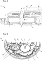
- the figure 4 shows a part 10 of a self-winding movement comprising the barrel 1 according to the invention.
- This part 10 comprises a plate 17 of the movement, an oscillating weight 18, a barrel bridge 19, a bridge 21 of the automatic winding system, gears 22 of the needle display system of the timepiece.
- the plate 17 and the two bridges 19, 21 are substantially parallel. From bottom to top, we find the plate 17, the barrel bridge 19, the bridge 21 of the automatic winding system and the oscillating weight 18.
- the gears 22 are arranged next to the barrel bridge 19, under the bridge 21 of the system. automatic winding.
- the barrel 1 is mounted between the plate 17 and the barrel bridge 19. To this end, the outgoing end 9 of the shaft 4 passes through the barrel bridge 19 and the ratchet 3, the ratchet 3 being arranged on the barrel bridge 19, below the bridge of the automatic winding system 21.
- the other free end 23 of the shaft is assembled to the plate 17 while being free to rotate about its axis relative to the latter.
- the movement 20 is similar, but does not have an automatic winding system.
- the ratchet 3 is engaged with a crown wheel 25, which can be actuated from the outer crown of the timepiece, the crown not being shown in the figures.
- the crown wheel 25 engages the ratchet 3, which rotates the shaft of the barrel 4 to force the spring inside the drum 2, and to wind the spring.
- the ratchet locking pawl 26 is arranged on the crown wheel 25 instead of the ratchet 3 directly. The pawl 26 makes it possible to rotate the crown wheel 25 in one direction, the direction allowing the spring to be wound up.
- the invention also relates to a timepiece, not shown in the figures, comprising such a timepiece movement.
Landscapes
- Physics & Mathematics (AREA)
- General Physics & Mathematics (AREA)
- Electromechanical Clocks (AREA)
- Transmission Devices (AREA)
- Measurement Of Unknown Time Intervals (AREA)
Priority Applications (4)
| Application Number | Priority Date | Filing Date | Title |
|---|---|---|---|
| EP20159421.5A EP3872576B1 (de) | 2020-02-25 | 2020-02-25 | Federgehäuse eines uhrwerks mit verdrehter welle |
| US17/166,545 US11782386B2 (en) | 2020-02-25 | 2021-02-03 | Timepiece barrel with a twisted arbour |
| JP2021018918A JP7116815B2 (ja) | 2020-02-25 | 2021-02-09 | ねじれたアーバーを備える計時器用バレル |
| CN202110210265.4A CN113376994B (zh) | 2020-02-25 | 2021-02-25 | 带有扭转条轴的时计发条盒 |
Applications Claiming Priority (1)
| Application Number | Priority Date | Filing Date | Title |
|---|---|---|---|
| EP20159421.5A EP3872576B1 (de) | 2020-02-25 | 2020-02-25 | Federgehäuse eines uhrwerks mit verdrehter welle |
Publications (2)
| Publication Number | Publication Date |
|---|---|
| EP3872576A1 true EP3872576A1 (de) | 2021-09-01 |
| EP3872576B1 EP3872576B1 (de) | 2024-02-21 |
Family
ID=69740174
Family Applications (1)
| Application Number | Title | Priority Date | Filing Date |
|---|---|---|---|
| EP20159421.5A Active EP3872576B1 (de) | 2020-02-25 | 2020-02-25 | Federgehäuse eines uhrwerks mit verdrehter welle |
Country Status (4)
| Country | Link |
|---|---|
| US (1) | US11782386B2 (de) |
| EP (1) | EP3872576B1 (de) |
| JP (1) | JP7116815B2 (de) |
| CN (1) | CN113376994B (de) |
Citations (3)
| Publication number | Priority date | Publication date | Assignee | Title |
|---|---|---|---|---|
| EP2196866A2 (de) * | 2008-12-15 | 2010-06-16 | Les Artisans Horlogers Sàrl | Assembly comprising a ratchet-wheel fixed to the barrel-arbor and barrel-arbor for this assembly |
| EP2657794A1 (de) * | 2012-04-25 | 2013-10-30 | ETA SA Manufacture Horlogère Suisse | Federwelle und Zugfeder |
| CH713951A2 (fr) * | 2017-07-03 | 2019-01-15 | Eta Sa Mft Horlogere Suisse | Barillet d'horlogerie à diamètre de bonde réduit. |
Family Cites Families (8)
| Publication number | Priority date | Publication date | Assignee | Title |
|---|---|---|---|---|
| JPS59595Y2 (ja) * | 1976-02-27 | 1984-01-09 | 東芝医療用品株式会社 | 紫外線インジケ−タ |
| JP2005156344A (ja) | 2003-11-26 | 2005-06-16 | Seiko Epson Corp | ぜんまい装置、およびこれを備えた時計 |
| JP2008196549A (ja) * | 2007-02-09 | 2008-08-28 | Toyoda Gosei Co Ltd | 取付構造体 |
| KR101432480B1 (ko) * | 2011-04-15 | 2014-08-21 | (주)백산오피씨 | 감광 드럼용 구동 결합체, 감광 드럼 조립체, 프로세스 카트리지, 및 이미지 생성장치 |
| EP2570862B1 (de) * | 2011-09-15 | 2014-03-05 | ETA SA Manufacture Horlogère Suisse | Uhren-Federgehäusebaugruppe mit reduziertem Bunddurchmesser |
| EP2746868B1 (de) * | 2012-12-18 | 2016-04-27 | ETA SA Manufacture Horlogère Suisse | Federgehäuse einer Uhr |
| JP6874341B2 (ja) * | 2016-11-22 | 2021-05-19 | セイコーエプソン株式会社 | 時計用駆動機構、機械式時計およびゼンマイの操作方法 |
| JP6653731B2 (ja) * | 2018-06-13 | 2020-02-26 | セイコーインスツル株式会社 | 香箱アセンブリ、ムーブメント及び時計 |
-
2020
- 2020-02-25 EP EP20159421.5A patent/EP3872576B1/de active Active
-
2021
- 2021-02-03 US US17/166,545 patent/US11782386B2/en active Active
- 2021-02-09 JP JP2021018918A patent/JP7116815B2/ja active Active
- 2021-02-25 CN CN202110210265.4A patent/CN113376994B/zh active Active
Patent Citations (3)
| Publication number | Priority date | Publication date | Assignee | Title |
|---|---|---|---|---|
| EP2196866A2 (de) * | 2008-12-15 | 2010-06-16 | Les Artisans Horlogers Sàrl | Assembly comprising a ratchet-wheel fixed to the barrel-arbor and barrel-arbor for this assembly |
| EP2657794A1 (de) * | 2012-04-25 | 2013-10-30 | ETA SA Manufacture Horlogère Suisse | Federwelle und Zugfeder |
| CH713951A2 (fr) * | 2017-07-03 | 2019-01-15 | Eta Sa Mft Horlogere Suisse | Barillet d'horlogerie à diamètre de bonde réduit. |
Also Published As
| Publication number | Publication date |
|---|---|
| JP2021135291A (ja) | 2021-09-13 |
| EP3872576B1 (de) | 2024-02-21 |
| US20210263471A1 (en) | 2021-08-26 |
| JP7116815B2 (ja) | 2022-08-10 |
| CN113376994A (zh) | 2021-09-10 |
| US11782386B2 (en) | 2023-10-10 |
| CN113376994B (zh) | 2022-12-09 |
Similar Documents
| Publication | Publication Date | Title |
|---|---|---|
| EP2634649B1 (de) | Ökonomisches Federgehäuse für Uhrwerk | |
| EP2196866B1 (de) | Assembly comprising a ratchet-wheel fixed to the barrel-arbor and barrel-arbor for this assembly | |
| EP2570862A1 (de) | Uhren-Federgehäusebaugruppe mit reduziertem Bunddurchmesser | |
| EP3872576B1 (de) | Federgehäuse eines uhrwerks mit verdrehter welle | |
| EP2756358B1 (de) | Uhren-federgehäuse mit reduziertem kernesdurchmesser | |
| EP2834712B1 (de) | Federhaus, das eine zugfeder und eine federhauswelle umfasst | |
| EP3179315B1 (de) | Spiralklötzchenträger mit gesicherter montage | |
| EP1923754B1 (de) | Mit einem Anzeigemodul ausgerüstetes Uhrwerk | |
| CH717168A2 (fr) | Barillet d'horlogerie à arbre vrillé. | |
| FR3012189A1 (fr) | Dispositif de serrage a douilles multiples | |
| CH713951B1 (fr) | Barillet d'horlogerie à diamètre de bonde réduit. | |
| EP2977827A1 (de) | Federgehäuse einer Uhr mit verbesserter Kraftübertragung | |
| EP3339966B1 (de) | Drucktaste für eine uhr | |
| EP3889690A1 (de) | Sperrklinke für uhrwerk | |
| CH717287A2 (fr) | Cliquet d'arrêt pour mouvement d'horlogerie. | |
| CH717288A2 (fr) | Cliquet d'arrêt pour mouvement d'horlogerie. | |
| EP3805869A1 (de) | Geschraubte krone | |
| EP1566708B1 (de) | Aufzugsvorrichtung | |
| EP3218770B1 (de) | Antriebsorgan für uhrwerk | |
| FR3009043A1 (fr) | Ensemble a vis auto-adaptatif | |
| WO2017005394A1 (fr) | Arbre de barillet d'horlogerie | |
| CN208766466U (zh) | 具有减小的芯部直径的钟表发条盒 | |
| EP4375756A1 (de) | Aufzugsvorrichtung, insbesondere für eine uhr, mit einer entkuppelbaren sperrklinke | |
| CH720260A2 (fr) | Dispositif de remontage, notamment d'un barillet d'horlogerie, muni d'un rochet débrayable | |
| EP2570865A1 (de) | Uhren-Federgehäusebaugruppe mit reduziertem Federkerndurchmesser |
Legal Events
| Date | Code | Title | Description |
|---|---|---|---|
| PUAI | Public reference made under article 153(3) epc to a published international application that has entered the european phase |
Free format text: ORIGINAL CODE: 0009012 |
|
| STAA | Information on the status of an ep patent application or granted ep patent |
Free format text: STATUS: THE APPLICATION HAS BEEN PUBLISHED |
|
| AK | Designated contracting states |
Kind code of ref document: A1 Designated state(s): AL AT BE BG CH CY CZ DE DK EE ES FI FR GB GR HR HU IE IS IT LI LT LU LV MC MK MT NL NO PL PT RO RS SE SI SK SM TR |
|
| STAA | Information on the status of an ep patent application or granted ep patent |
Free format text: STATUS: REQUEST FOR EXAMINATION WAS MADE |
|
| 17P | Request for examination filed |
Effective date: 20220301 |
|
| RBV | Designated contracting states (corrected) |
Designated state(s): AL AT BE BG CH CY CZ DE DK EE ES FI FR GB GR HR HU IE IS IT LI LT LU LV MC MK MT NL NO PL PT RO RS SE SI SK SM TR |
|
| P01 | Opt-out of the competence of the unified patent court (upc) registered |
Effective date: 20230701 |
|
| GRAP | Despatch of communication of intention to grant a patent |
Free format text: ORIGINAL CODE: EPIDOSNIGR1 |
|
| STAA | Information on the status of an ep patent application or granted ep patent |
Free format text: STATUS: GRANT OF PATENT IS INTENDED |
|
| INTG | Intention to grant announced |
Effective date: 20230915 |
|
| GRAS | Grant fee paid |
Free format text: ORIGINAL CODE: EPIDOSNIGR3 |
|
| GRAA | (expected) grant |
Free format text: ORIGINAL CODE: 0009210 |
|
| STAA | Information on the status of an ep patent application or granted ep patent |
Free format text: STATUS: THE PATENT HAS BEEN GRANTED |
|
| RIN1 | Information on inventor provided before grant (corrected) |
Inventor name: KAELIN, LAURENT Inventor name: CHRISTAN, JULIEN |
|
| AK | Designated contracting states |
Kind code of ref document: B1 Designated state(s): AL AT BE BG CH CY CZ DE DK EE ES FI FR GB GR HR HU IE IS IT LI LT LU LV MC MK MT NL NO PL PT RO RS SE SI SK SM TR |
|
| REG | Reference to a national code |
Ref country code: GB Ref legal event code: FG4D Free format text: NOT ENGLISH |
|
| REG | Reference to a national code |
Ref country code: CH Ref legal event code: EP |
|
| REG | Reference to a national code |
Ref country code: IE Ref legal event code: FG4D Free format text: LANGUAGE OF EP DOCUMENT: FRENCH |
|
| REG | Reference to a national code |
Ref country code: DE Ref legal event code: R096 Ref document number: 602020025894 Country of ref document: DE |
|
| PGFP | Annual fee paid to national office [announced via postgrant information from national office to epo] |
Ref country code: DE Payment date: 20240215 Year of fee payment: 5 Ref country code: CH Payment date: 20240321 Year of fee payment: 5 Ref country code: GB Payment date: 20240320 Year of fee payment: 5 |
|
| PGFP | Annual fee paid to national office [announced via postgrant information from national office to epo] |
Ref country code: FR Payment date: 20240320 Year of fee payment: 5 |
|
| REG | Reference to a national code |
Ref country code: LT Ref legal event code: MG9D |
|
| REG | Reference to a national code |
Ref country code: NL Ref legal event code: MP Effective date: 20240221 |
|
| PG25 | Lapsed in a contracting state [announced via postgrant information from national office to epo] |
Ref country code: IS Free format text: LAPSE BECAUSE OF FAILURE TO SUBMIT A TRANSLATION OF THE DESCRIPTION OR TO PAY THE FEE WITHIN THE PRESCRIBED TIME-LIMIT Effective date: 20240621 |
|
| PG25 | Lapsed in a contracting state [announced via postgrant information from national office to epo] |
Ref country code: LT Free format text: LAPSE BECAUSE OF FAILURE TO SUBMIT A TRANSLATION OF THE DESCRIPTION OR TO PAY THE FEE WITHIN THE PRESCRIBED TIME-LIMIT Effective date: 20240221 |
|
| PG25 | Lapsed in a contracting state [announced via postgrant information from national office to epo] |
Ref country code: GR Free format text: LAPSE BECAUSE OF FAILURE TO SUBMIT A TRANSLATION OF THE DESCRIPTION OR TO PAY THE FEE WITHIN THE PRESCRIBED TIME-LIMIT Effective date: 20240522 |
|
| REG | Reference to a national code |
Ref country code: AT Ref legal event code: MK05 Ref document number: 1659623 Country of ref document: AT Kind code of ref document: T Effective date: 20240221 |
|
| PG25 | Lapsed in a contracting state [announced via postgrant information from national office to epo] |
Ref country code: HR Free format text: LAPSE BECAUSE OF FAILURE TO SUBMIT A TRANSLATION OF THE DESCRIPTION OR TO PAY THE FEE WITHIN THE PRESCRIBED TIME-LIMIT Effective date: 20240221 Ref country code: NL Free format text: LAPSE BECAUSE OF FAILURE TO SUBMIT A TRANSLATION OF THE DESCRIPTION OR TO PAY THE FEE WITHIN THE PRESCRIBED TIME-LIMIT Effective date: 20240221 Ref country code: RS Free format text: LAPSE BECAUSE OF FAILURE TO SUBMIT A TRANSLATION OF THE DESCRIPTION OR TO PAY THE FEE WITHIN THE PRESCRIBED TIME-LIMIT Effective date: 20240521 |
|
| PG25 | Lapsed in a contracting state [announced via postgrant information from national office to epo] |
Ref country code: ES Free format text: LAPSE BECAUSE OF FAILURE TO SUBMIT A TRANSLATION OF THE DESCRIPTION OR TO PAY THE FEE WITHIN THE PRESCRIBED TIME-LIMIT Effective date: 20240221 |
|
| PG25 | Lapsed in a contracting state [announced via postgrant information from national office to epo] |
Ref country code: AT Free format text: LAPSE BECAUSE OF FAILURE TO SUBMIT A TRANSLATION OF THE DESCRIPTION OR TO PAY THE FEE WITHIN THE PRESCRIBED TIME-LIMIT Effective date: 20240221 |
|
| PG25 | Lapsed in a contracting state [announced via postgrant information from national office to epo] |
Ref country code: RS Free format text: LAPSE BECAUSE OF FAILURE TO SUBMIT A TRANSLATION OF THE DESCRIPTION OR TO PAY THE FEE WITHIN THE PRESCRIBED TIME-LIMIT Effective date: 20240521 Ref country code: NO Free format text: LAPSE BECAUSE OF FAILURE TO SUBMIT A TRANSLATION OF THE DESCRIPTION OR TO PAY THE FEE WITHIN THE PRESCRIBED TIME-LIMIT Effective date: 20240521 Ref country code: NL Free format text: LAPSE BECAUSE OF FAILURE TO SUBMIT A TRANSLATION OF THE DESCRIPTION OR TO PAY THE FEE WITHIN THE PRESCRIBED TIME-LIMIT Effective date: 20240221 Ref country code: LT Free format text: LAPSE BECAUSE OF FAILURE TO SUBMIT A TRANSLATION OF THE DESCRIPTION OR TO PAY THE FEE WITHIN THE PRESCRIBED TIME-LIMIT Effective date: 20240221 Ref country code: IS Free format text: LAPSE BECAUSE OF FAILURE TO SUBMIT A TRANSLATION OF THE DESCRIPTION OR TO PAY THE FEE WITHIN THE PRESCRIBED TIME-LIMIT Effective date: 20240621 Ref country code: HR Free format text: LAPSE BECAUSE OF FAILURE TO SUBMIT A TRANSLATION OF THE DESCRIPTION OR TO PAY THE FEE WITHIN THE PRESCRIBED TIME-LIMIT Effective date: 20240221 Ref country code: GR Free format text: LAPSE BECAUSE OF FAILURE TO SUBMIT A TRANSLATION OF THE DESCRIPTION OR TO PAY THE FEE WITHIN THE PRESCRIBED TIME-LIMIT Effective date: 20240522 Ref country code: FI Free format text: LAPSE BECAUSE OF FAILURE TO SUBMIT A TRANSLATION OF THE DESCRIPTION OR TO PAY THE FEE WITHIN THE PRESCRIBED TIME-LIMIT Effective date: 20240221 Ref country code: ES Free format text: LAPSE BECAUSE OF FAILURE TO SUBMIT A TRANSLATION OF THE DESCRIPTION OR TO PAY THE FEE WITHIN THE PRESCRIBED TIME-LIMIT Effective date: 20240221 Ref country code: BG Free format text: LAPSE BECAUSE OF FAILURE TO SUBMIT A TRANSLATION OF THE DESCRIPTION OR TO PAY THE FEE WITHIN THE PRESCRIBED TIME-LIMIT Effective date: 20240221 Ref country code: AT Free format text: LAPSE BECAUSE OF FAILURE TO SUBMIT A TRANSLATION OF THE DESCRIPTION OR TO PAY THE FEE WITHIN THE PRESCRIBED TIME-LIMIT Effective date: 20240221 |
|
| PG25 | Lapsed in a contracting state [announced via postgrant information from national office to epo] |
Ref country code: PT Free format text: LAPSE BECAUSE OF FAILURE TO SUBMIT A TRANSLATION OF THE DESCRIPTION OR TO PAY THE FEE WITHIN THE PRESCRIBED TIME-LIMIT Effective date: 20240621 Ref country code: PL Free format text: LAPSE BECAUSE OF FAILURE TO SUBMIT A TRANSLATION OF THE DESCRIPTION OR TO PAY THE FEE WITHIN THE PRESCRIBED TIME-LIMIT Effective date: 20240221 |
|
| PG25 | Lapsed in a contracting state [announced via postgrant information from national office to epo] |
Ref country code: SE Free format text: LAPSE BECAUSE OF FAILURE TO SUBMIT A TRANSLATION OF THE DESCRIPTION OR TO PAY THE FEE WITHIN THE PRESCRIBED TIME-LIMIT Effective date: 20240221 Ref country code: PT Free format text: LAPSE BECAUSE OF FAILURE TO SUBMIT A TRANSLATION OF THE DESCRIPTION OR TO PAY THE FEE WITHIN THE PRESCRIBED TIME-LIMIT Effective date: 20240621 Ref country code: PL Free format text: LAPSE BECAUSE OF FAILURE TO SUBMIT A TRANSLATION OF THE DESCRIPTION OR TO PAY THE FEE WITHIN THE PRESCRIBED TIME-LIMIT Effective date: 20240221 Ref country code: LV Free format text: LAPSE BECAUSE OF FAILURE TO SUBMIT A TRANSLATION OF THE DESCRIPTION OR TO PAY THE FEE WITHIN THE PRESCRIBED TIME-LIMIT Effective date: 20240221 |