EP3872016A1 - Sicherheitsanordnung für eine aufzuganordnung - Google Patents
Sicherheitsanordnung für eine aufzuganordnung Download PDFInfo
- Publication number
- EP3872016A1 EP3872016A1 EP20160052.5A EP20160052A EP3872016A1 EP 3872016 A1 EP3872016 A1 EP 3872016A1 EP 20160052 A EP20160052 A EP 20160052A EP 3872016 A1 EP3872016 A1 EP 3872016A1
- Authority
- EP
- European Patent Office
- Prior art keywords
- elevator
- safety
- shaft portion
- lowermost
- shaft
- Prior art date
- Legal status (The legal status is an assumption and is not a legal conclusion. Google has not performed a legal analysis and makes no representation as to the accuracy of the status listed.)
- Withdrawn
Links
- 230000004888 barrier function Effects 0.000 claims abstract description 12
- 230000008859 change Effects 0.000 claims abstract description 10
- 238000007689 inspection Methods 0.000 claims description 47
- 239000000872 buffer Substances 0.000 description 14
- 230000008439 repair process Effects 0.000 description 4
- 238000010276 construction Methods 0.000 description 3
- 238000012423 maintenance Methods 0.000 description 3
- 230000007246 mechanism Effects 0.000 description 3
- 230000003213 activating effect Effects 0.000 description 2
- 230000000415 inactivating effect Effects 0.000 description 2
- 238000012544 monitoring process Methods 0.000 description 2
- 230000009286 beneficial effect Effects 0.000 description 1
- 230000008901 benefit Effects 0.000 description 1
- 230000004397 blinking Effects 0.000 description 1
- 230000003287 optical effect Effects 0.000 description 1
Images


Classifications
-
- B—PERFORMING OPERATIONS; TRANSPORTING
- B66—HOISTING; LIFTING; HAULING
- B66B—ELEVATORS; ESCALATORS OR MOVING WALKWAYS
- B66B5/00—Applications of checking, fault-correcting, or safety devices in elevators
- B66B5/0006—Monitoring devices or performance analysers
- B66B5/0018—Devices monitoring the operating condition of the elevator system
- B66B5/0031—Devices monitoring the operating condition of the elevator system for safety reasons
-
- B—PERFORMING OPERATIONS; TRANSPORTING
- B66—HOISTING; LIFTING; HAULING
- B66B—ELEVATORS; ESCALATORS OR MOVING WALKWAYS
- B66B5/00—Applications of checking, fault-correcting, or safety devices in elevators
- B66B5/28—Buffer-stops for cars, cages, or skips
- B66B5/284—Buffer-stops for cars, cages, or skips mounted on cars or counterweights
- B66B5/286—Buffer-stops for cars, cages, or skips mounted on cars or counterweights between two cars or two counterweights
-
- B—PERFORMING OPERATIONS; TRANSPORTING
- B66—HOISTING; LIFTING; HAULING
- B66B—ELEVATORS; ESCALATORS OR MOVING WALKWAYS
- B66B17/00—Hoistway equipment
- B66B17/36—Gates or other apparatus controlling access to, or exit from, cars, cages, or hoistway landings
Definitions
- the present invention relates to a safety arrangement for an elevator arrangement in accordance with claim 1.
- High-rise buildings usually accommodate several elevators.
- the elevator configuration in such buildings typically depends on the people flow requirements of different floors in the building.
- the top floors may be reserved for residential use while the lower floors may accommodate offices and businesses.
- some of the elevators may serve passengers on a floor-by-floor basis and others may serve as shuttle elevators, providing a fast transfer between the building entrance lobby and a so-called sky lobby for the residents to change to a floor-by-floor elevator serving the residential floors.
- different elevators may be separated from each other.
- the shafts may be horizontally apart from each other, or vertically aligned, but separated by a concrete slab or other fixed structure.
- each elevator shaft is provided with a top refuge space and the lower end with a pit refuge space.
- the refuge spaces ensure that a person working in the shaft does not get squeezed between a moving elevator and an end of the shaft.
- a drawback of the known solutions is that a significant amount of space is needed for the refuge spaces.
- An object of the present invention is to provide an improved safety arrangement for an elevator arrangement which comprises a lower elevator and an upper elevator arranged within an elevator shaft, the elevator shaft comprising a lower shaft portion, the lower shaft portion comprising at least a lowermost landing and an uppermost landing, and an upper shaft portion, the upper shaft portion comprising at least a lowermost landing and an uppermost landing, the lowermost landing of the upper shaft portion being above the uppermost landing of the lower shaft portion, each shaft portion being provided with an elevator car which is configured to move between the lowermost landing and the uppermost landing of the respective shaft portion.
- the safety arrangement comprises one or more physical barriers for forming a shared safety space between the lower shaft portion and the upper shaft portion, and the safety arrangement is configured to monitor a group of predetermined trigger events of the lower elevator and the upper elevator, and to change the operational state of at least one of the lower elevator and the upper elevator when a trigger event occurs.
- An elevator arrangement where two or more elevator cars are arranged to move within a common elevator shaft brings additional risk factors compared to normal elevators where a single elevator car serves the elevator shaft.
- the safety arrangement according to the invention improves the safety of the persons conducting service or repair work within the elevator shaft. Because of the barriers between the shaft portions, a safety space common to both shaft portions is formed, which saves space. By monitoring the trigger events and changing the operational state of at least one of the lower elevator and the upper elevator when a trigger event occurs, working is safe even in the area between the two shaft portions.
- the safety arrangement is configured to change the operational state of both the lower elevator and the upper elevator when a trigger event occurs. In some cases, it is necessary to change the operational state of both elevators to ensure safety.
- the safety arrangement is configured to switch both the lower elevator and the upper elevator to a safety mode when a trigger event occurs.
- the operation of the elevators can be restricted in various ways. Switching to the safety mode can take place in connection with certain trigger events, whereas certain other trigger events can change the operational state of at least one of the elevators to another state.
- the switching to the safety mode stops both the lower elevator car and the upper elevator car.
- the switching to the safety mode prevents moving of at least one of the elevator cars.
- the switching to the safety mode prevents moving of both the lower elevator car and the upper elevator car. It is also possible that only some of the trigger events are configured to prevent moving of both elevator cars, whereas some trigger events are configured to prevent moving of one of the elevator cars only.
- the group of predetermined trigger events includes at least one of the following events: unlocking of a shaft access door for emergency or service opening, pushing of a stop button of the lower elevator or the upper elevator, and opening of a ladder within the elevator shaft.
- the trigger events may thus include events relating to access to the area between the shaft portions or to work conducted in the area.
- the shaft access doors include the doors of the lowermost landing of the upper elevator and the doors of all landings of the lower elevator except for the lowermost landing.
- the shaft access doors can thus include those doors which provide access to the area between the shaft portions. The area can be accessed from the lowermost landing of the upper elevator or on the roof of the lower elevator car from any landing of the lower elevator, except for the lowermost landing.
- the safety arrangement comprises a safety circuit shared by the lower elevator and the upper elevator. This allows a simple way of controlling the operation of both elevators.
- each elevator can be provided with an own safety circuit.
- the group of predetermined trigger events includes switching at least one of the elevators to an inspection drive mode.
- switching one of the elevators to the inspection drive mode prevents moving of the other elevator.
- the arrangement comprises means for detecting whether the elevator car of the lower elevator is at a predetermined inspection drive zone close to the uppermost landing of the lower elevator, and the upper elevator can be operated in an inspection drive mode only on the condition that the lower elevator is at the inspection drive zone. This ensures that the person conducting an inspection drive of the upper elevator is close to the upper elevator.
- the elevator shaft is provided with a foldable or turnable ladder for providing access from the lowermost landing of the upper elevator to the roof of the elevator car of the lower elevator.
- the ladder is provided with a locking arrangement preventing opening of the ladder to a use position when the elevator car of the lower elevator is not between the topmost position and the uppermost landing of the lower shaft portion. This ensures that the roof of the elevator car of the lower elevator can be used as safe platform when descending from the lowermost landing of the upper elevator.
- the safety arrangement is configured to disable moving of the elevator car of the upper elevator when the ladder is not in a closed position.
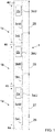
- FIG. 1 shows schematically an elevator arrangement.
- the elevator arrangement comprises three elevators: a lowermost elevator, a middle elevator and an uppermost elevator.
- the figure is very simplified and omits many features that are not important for describing the present invention. For instance, hoisting members, counterweights, end buffers and guide rails of the elevators are not shown.
- the elevators share a common elevator shaft 1.
- the elevator shaft 1 extends in the vertical direction over a plurality of floors of a building and/or an underground space.
- the elevator shaft 1 is divided into shaft portions 1a, 1b, 1c.
- the shaft portions 1a, 1b, 1c are arranged one upon the other.
- the elevator shaft 1 of figure 1 comprises a lowermost shaft portion 1a, a middle shaft portion 1b and an uppermost shaft portion 1c.
- the middle shaft portion 1b is arranged above the lowermost shaft portion 1a and the uppermost shaft portion 1c is arranged above the middle shaft portion 1b.
- Each shaft portion 1a, 1b, 1c comprises at least two landings, i.e. at least a lowermost landing and an uppermost landing.
- each shaft portion 1a, 1b, 1c comprises a lowermost landing 3aL, 3bL, 3cL and an uppermost landing 3aU, 3bU, 3cU. Between the lowermost landing and the uppermost landing there is a middle landing 3aM, 3bM, 3cM. There could also be several middle landings in each shaft portion 1a, 1b, 1c.
- the shaft portions 1a, 1b, 1c do not have to have the same number of landings with each other, but there can be a different number of landings in each shaft portion 1a, 1b, 1c.
- Each shaft portion 1a, 1b, 1c is provided with an elevator car 2a, 2b, 2c.
- Each elevator car 2a, 2b, 2c is configured to move along the respective shaft portion 1a, 1b, 1c.
- the elevator car 2a of the lowermost shaft portion 1a can thus move between the lowermost landing 3aL and the uppermost landing 3aU of the lowermost shaft portion 1a.
- the elevator cars 2b, 2c of the middle shaft portion 1b and the uppermost shaft portion 1c can move between the lowermost and uppermost landings of the respective shaft portions 1b, 1c.
- Each elevator car 2a, 2b, 2c thus serves a dedicated portion of the elevator shaft 1.
- the lowermost elevator car 2a is configured to move below the middle shaft portion 1b
- the middle elevator car 2b is configured to move above the lowermost shaft portion 1a and below the uppermost shaft portion 1c
- the uppermost elevator 1c is configured to move above the middle shaft portion 1b.
- the elevator cars 2a, 2b, 2c are configured to move independently from each other.
- safety space refers here to a refuge space, to which the elevator car 2a, 2b, 2c cannot ascend or descend.
- the elevator shaft 1 is provided with physical barriers (not shown in figure 1 ) which prevent the elevator cars 2a, 2b, 2c to ascend or descend to the areas of the safety spaces 4a, 4b, 4c, 4d.
- the height and other dimensions of the safety spaces 4a, 4b, 4c, 4d depend on regulations in the jurisdiction where the elevator arrangement is used.
- the safety spaces 4a, 4b, 4c, 4d allow safe inspection, maintenance and repair work within the elevator shaft 1.
- a lowermost safety space 4a is formed in the pit of the lowermost elevator.
- An uppermost safety space 4d is formed in the headroom of the uppermost elevator.
- the elevator shaft 1 is open between the lowermost shaft portion 1a and the middle shaft portion 1b.
- the elevator shaft 1 is open between the middle shaft portion 1b and the uppermost shaft portion 1c. There are thus no slabs or other similar barriers dividing the shaft 1 into the shaft portions 1a, 1b, 1c. Between the shaft portions, there are physical barriers like buffers for forming the safety spaces 4b, 4c between the shaft portions, but there is an access from a lower shaft portion to an upper shaft portion and vice versa.
- the height required from the safety spaces depends on the relevant regulations. If the elevator shaft 1 was divided by means of slabs or similar constructions into the shaft portions 1a, 1b, 1c, two separate safety spaces would be needed between two successive shaft portions. The minimum distance between two successive elevator cars would thus be two times the minimum height of a safety space plus the thickness of the slab or other construction dividing the elevator shaft plus a certain distance allowed for over travel of each elevator car. This means that the minimum floor-to-floor distance would be greater between the uppermost landing of a lower elevator and the lowermost landing of an upper elevator than between two landings of one of the elevators.
- the required space between two successive elevators can be significantly reduced, which allows using the same floor height in the whole building. This is beneficial especially in buildings which are provided with high-rise elevators and low-rise elevators. For instance, transfer floors for a double-decker elevator can be made with one common stop for both cars of the double-decker elevator and the floor-to-floor distance of the transfer floors can be reduced.
- the elevator shaft 1 is divided into different safety segments. The division into the safety segments is based on access into the safety spaces 4a, 4b, 4c, 4d of the elevator shaft 1.
- a first safety segment 26 extends from the bottom of the elevator shaft 1 to above the lowermost landing 3aL of the lowermost shaft portion 1a. The lowermost landing 3aL provides access only into the safety space 4a of the pit of the elevator shaft 1.
- a second safety segment 27 extends from below the next landing 3aM of the lowermost shaft portion 1a to above the lowermost landing 3bL of the middle shaft portion 1b, because this segment 27 provides access into the shared safety space 4b between the lowermost shaft portion 1a and the middle shaft portion 1b.
- a third safety segment 28 extends from below the landing 3bM that is located above the lowermost landing 3bL of the middle shaft portion 1 b to above the lowermost landing 3cL of the uppermost shaft portion 1c. The landings within this segment 28 provide access to the shared safety space 4c between the middle shaft portion 1b and the uppermost shaft portion 1c.
- a fourth safety segment 29 extends from above the lowermost landing 3cL of the uppermost shaft portion 1c to the top of the elevator shaft 1. The landings within this segment 29 provide access only to the safety space 4d of the headroom of the elevator shaft 1.
- Figures 2a and 2b show physical barriers arranged between the lowermost shaft portion 1a and the middle shaft portion 1b for forming the shared safety space 4b.
- the barriers comprise at least one buffer 13, 14 for each of the elevator car 2a of the lowermost elevator and the elevator car 2b of the middle elevator.
- the barriers may further comprise buffers for the counterweights of the elevators. In the horizontal direction, the barriers delimit the safety space 4b. The safety space 4b is thus between the barriers.
- the purpose of the buffers is to stop the elevator car 2a, 2b or the counterweight if it descends or ascends beyond its normal moving range.
- the buffers 13, 14 are configured to accumulate or dissipate the kinetic energy of the elevator car 2a, 2b or the counterweight in case the elevator car 2a, 2b or the counterweight hits the buffer 13, 14 and thus limit the deceleration of the elevator car 2a, 2b or the counterweight in such a situation.
- Figure 2a shows a situation, where the elevator car 2a of the lowermost elevator is at the uppermost landing and the elevator car 2b of the middle elevator is at the lowermost landing. As can be seen in the figure, a certain space for allowing overtravel of the elevator cars 2a, 2b is left between each elevator car 2a, 2b and the respective buffers 13, 14.
- Figure 2b shows a situation which should not occur during normal use of the elevators.
- the elevator car 2a of the lowermost elevator has hit the buffers 13 which have been compressed.
- the elevator car 2b of the middle elevator has hit the buffers 14 which have been compressed. Even in this worst-case scenario, a safety space 4b is left between the elevator cars 2a, 2b.
- the buffers 13, 14 are attached to the walls of the elevator shaft 1 and to guide rails for directing vertical forces exerted on the buffers 13, 14 to fixed constructions.
- the safety spaces 4a, 4b, 4c, 4d ensure that a person working in the elevator shaft 1 does not get squeezed between two successive elevator cars or between an elevator car 2a, 2c and an end of the elevator shaft 1.
- an additional requirement for safe work in the elevator shaft 1 is that the elevator cars 2a, 2b, 2c in a shaft area where a person is working are immobilized or at least the movement of the elevator cars 2a, 2b, 2c is restricted.
- the operation of the elevators may be allowed only in an inspection drive mode. In the inspection drive mode, the moving speed of the elevator may be reduced compared to the moving speed during normal operation of the elevator. When a person is working in the pit of the lowermost shaft portion 1a, the middle elevator and the uppermost elevator may be operated normally.
- Each elevator car 2a, 2b, 2c serves only a dedicated segment of the elevator shaft 1 and only the lowermost elevator car 2a can reach the pit of the elevator shaft 1. Similarly, when a person is working above the uppermost elevator car 2c, the middle elevator and the lowermost elevator can be operated normally, because there is no risk that the person ends up between the uppermost elevator car 2c and one of the other two elevator cars 2a, 2b.
- the elevator arrangement comprises a safety arrangement which is configured to monitor a group of predetermined trigger events of a lower elevator and an upper elevator, and to change the operational state of at least one of the lower elevator and the upper elevator when a trigger event occurs.
- the safety arrangement thus monitors certain trigger events of the lowermost elevator and the middle elevator and changes the operational state of the lowermost elevator and/or the middle elevator when a trigger event occurs.
- a safety arrangement monitors certain trigger events of the middle elevator and the uppermost elevator and changes the operational state of the middle elevator and/or the uppermost elevator when a trigger event occurs.
- the operational state of the one or two elevators is changed to a state where the operation of the elevator(s) is restricted.
- the restricted operation can include that the elevator can be moved only with a reduced speed and/or moving of the elevator is allowed only in case certain conditions which are not required during normal operation are fulfilled.
- Certain trigger events may be configured to switch at least one of the elevators to a safety mode.
- the safety mode only limited operation of the elevators is allowed.
- the switching to the safety mode can stop both the lower elevator car and the upper elevator car and/or prevent movement one of the elevator cars or movement of both elevator cars. After the elevator cars have been stopped and the movement of the elevator cars has been prevented, movement of the elevator cars may be allowed only when certain conditions are met.
- the trigger events may be selected so that they represent at least situations where the elevator shaft 1 is accessed from shaft access doors providing access to a shared safety space 4b, 4c between two successive shaft portions.
- a shared safety space 4b, 4c can be accessed via the doors of the lowermost landing 3bL, 3cL of a shaft portion that is above another shaft portion.
- the safety space 4b can be accessed via the doors of the lowermost landing 3bL of the middle shaft portion 1b.
- the safety space 4c can be accessed via the doors of the lowermost landing 3cL of the uppermost shaft portion 1c.
- the safety space 4b between the lowermost shaft portion 1a and the middle shaft portion 1b can be accessed by entering the elevator shaft 1 via any shaft access door of the lowermost shaft portion 1 a above the lowermost landing 3aL of the lowermost shaft portion 1.
- the elevator car 2a of the lowermost elevator can then be driven to the uppermost landing 3aU of the lowermost shaft portion 1a.
- the safety space 4c between the middle shaft portion 1b and the uppermost shaft portion 1c can be accessed by entering the elevator shaft 1 via any shaft access door of the middle shaft portion 1b above the lowermost landing 3bL of the middle shaft portion 1 b.
- the elevator car 2b of the middle elevator can then be driven to the uppermost landing 3bU of the middle shaft portion 1b.
- the trigger events switching the lowermost elevator and the middle elevator to a safety mode can be events occurring within the second safety segment 27.
- the trigger events switching the middle elevator and the uppermost elevator can be events occurring within the third safety segment 28.
- a trigger event may thus be emergency or service opening of any of the doors of the landings of the lowermost elevator except for the door of the lowermost landing 3aL, or opening of the door of the lowermost landing 3bL of the middle elevator.
- a trigger event may be emergency or service opening of any of the doors of the landings of the middle elevator except for the door of the lowermost landing 3bL, or opening of the door of the lowermost landing 3cL of the uppermost elevator.
- the elevator shaft 1 could be provided with other doors providing access to the shaft 1 and opening of any of the doors located similarly as the above-mentioned doors of the landings could be a trigger event. Opening of a door within the second safety segment 27 would thus be a trigger event for the lowermost elevator and the middle elevator. Opening of a door within the third safety segment 28 would be a trigger event for the middle elevator and the uppermost elevator.
- the expression "emergency or service opening” means opening of a door of the shaft 1 for the purpose of accessing the shaft 1 when the respective elevator car 2a, 2b, 2c is not at the landing.
- the trigger events may include pushing of a stop button of either a lower or an upper elevator.
- the stop button may in particular be a stop button arranged within the elevator shaft 1, for instance in the wall of the elevator shaft or on the roof of an elevator car. Pushing of a stop button within the second safety segment 27 would thus be a trigger event for the lowermost elevator and middle elevator. Pushing of a stop button within the third safety segment 28 would be a trigger event for the middle elevator and the uppermost elevator.
- a trigger event can also be opening of a ladder arranged within the elevator shaft 1.
- Each of the shared safety spaces 4b, 4c between the lowermost shaft portion 1a and the middle shaft portion 1b and between the middle shaft portion 1b and the uppermost shaft portion 1c may be provided with a turnable or foldable ladder.
- the ladder may thus be arranged against an inner wall of the elevator shaft 1 and opened into a use position.
- the opening of the ladder into the use position may be detected as a trigger event.
- Opening of a ladder within the second safety segment 27 would thus be a trigger event for the lowermost elevator and middle elevator.
- Opening of a ladder within the third safety segment 28 would be a trigger event for the middle elevator and the uppermost elevator.
- FIG. 3 shows part of a safety circuit 25 that is shared by the lowermost elevator and the middle elevator.
- the safety circuit 25 is arranged to monitor doors 5 that provide access to the shared safety space 4b between the lowermost shaft portion 1a and the middle shaft portion 1b.
- the doors 5 include the door of the lowermost landing 3bL of the middle shaft portion 1 b and all other doors of the lowermost shaft portion 1a than the door of the lowermost landing 3aL.
- the doors 5 are provided with an emergency opening mechanism 6 which can be unlocked using a suitable key or tool.
- a maintenance person can thus unlock and open the door 5 even when the elevator car 2a, 2b is not at the landing for having access into the elevator shaft 1 for example for inspecting, servicing or repairing one of the elevators.
- the safety circuit 25 is provided with a contact 7 that is configured to detect opening of the emergency opening mechanism. Unlocking of the door 5 can thus be configured to change the status of the safety circuit 25. Unlocking of the door 5 can thus be detected by a safety control unit 8a, 8b. Each of the lowermost elevator and the middle elevator has an own safety control unit 8a, 8b. Unlocking of the above-mentioned doors 5 can be detected by both safety control units 8a, 8b.
- the safety control units 8a, 8b are configured to switch both elevators to a safety mode. Although the safety control units 8a, 8b are presented here as separate units, safety control functions of both elevators could be arranged in a common safety control unit.
- a ladder 9 is arranged between the lowermost shaft portion 1a and the middle shaft portion 1b.
- the ladder 9 is folded against the wall of the elevator shaft 1.
- the ladder 9 can be opened for descending from the lowermost landing 3bL of the middle shaft portion 1b onto the roof of the elevator car 2a of the lowermost elevator.
- the safety circuit 25 of figure 3 comprises a contact 10 for detecting opening of the ladder 9. Also this contact is connected to the safety control units 8a, 8b of both elevators.
- the middle elevator is provided with a stop button 11 which is arranged in the elevator shaft 1.
- the safety circuit 25 is provided with a contact 12 detecting pushing of the stop button 11.
- the contact 12 is connected to both safety control units 8a, 8b.
- Figure 4 shows an embodiment providing the same functionality as the embodiment of figure 3 .
- the lowermost elevator and the middle elevator are provided with separate safety circuits 26, 27.
- the safety circuit 26 of the lowermost elevator is illustrated with a continuous line and the safety circuit 27 of the middle elevator is illustrated with a dashed line.
- the emergency opening mechanisms 6 of the doors 5 are provided with double contacts 7a, 7b.
- a first contact 7a is connected to the safety circuit 26 of the lower elevator and a second contact 7b is connected to the safety circuit 27 of the middle elevator. Unlocking of the door 5 can thus be detected by a safety control unit 8a of the lower elevator and by a safety control unit 8b of the upper elevator.
- the ladder 9 is provided with double contacts 10a, 10b and the stop button 11 is provided with double contacts 12a, 12b.
- the arrangement of figure 4 requires more wiring than the arrangement of figure 3 but makes the safety control of the elevators simpler.
- a safety arrangement shared by the middle elevator and the upper elevator could be similar as in figures 3 and 4 .
- each elevator can comprise an own safety circuit.
- a safety circuit dedicated to one of the elevators can comprise, for instance, limit switches, overspeed governors, car door contacts, landing door contacts etc.
- the safety circuits can be based on programmable electronic systems.
- the safety circuits can be implemented according to standards for programmable electronic systems in safety-related applications for lifts (PESSRAL).
- Figure 5 shows the elevator cars 2a, 2b of the lowermost elevator and the middle elevator in the same positions as in figures 3 and 4 .
- the ladder 9 has been opened, i.e. folded to the use position.
- Figure 5 also shows a control unit 16 for inspection drive of the elevators.
- Figure 6 shows an enlarged view of the inspection drive control unit 16.
- the inspection drive control unit 16 can be used for driving both the lowermost elevator and the middle elevator, for instance for driving an elevator car 2a, 2b to a position allowing certain service or repair work or for testing the elevator.
- the inspection drive control unit 16 is located on the roof of the elevator car 2a of the lowermost elevator.
- the inspection drive control unit 16 comprises a selector 17 for activating an inspection drive mode for one of the elevators, i.e.
- the inspection drive control unit 16 is configured to allow inspection drive of only one elevator at a time.
- the selector 17 is also used for inactivating the inspection drive mode after the inspection drive by turning the selector 17 to the position "Inspection off”.
- the inspection drive control unit 16 comprises a stop button 18. Pushing of the stop button 18 is configured to stop both elevators. Pushing of the stop button 18 also immobilizes both elevators.
- the stop button 18 is connected to a shared safety circuit of the two elevators or, in case of separate safety circuits, to the safety circuits of both elevators.
- the inspection drive control unit 16 further comprises operating buttons 19, 20 for driving the selected elevator upwards or downwards.
- the inspection drive control unit 16 may further comprise a light switch for switching shaft lights of both the lowermost shaft portion 1a and the middle shaft portion 1b on and off.
- the top of the elevator car 2a of the lowermost elevator and the bottom of the elevator car 2b of the middle elevator can be provided with a warning device 23, 24 giving a warning sound and/or blinking a warning light when an inspection drive mode of the respective elevator is selected.
- warning lights can be arranged on top of the and at the bottom of the elevator cars 2a, 2b, and a warning device giving an audible signal can be arranged elsewhere in the elevator cars 2a, 2b or in the elevator shaft 1.
- the safety arrangement can be configured to allow inspection drive of the middle elevator only in case the elevator car 2a of the lowermost elevator is at a predetermined inspection drive zone. For instance, it may be required that the elevator car 2a of the lower elevator is between the topmost position and the uppermost landing 3aU of the lowermost shaft portion 1a. By determining an inspection drive zone, it is ensured that the person conducting the inspection drive of the middle elevator is not far from the elevator.
- the lowermost elevator can be provided with a limit switch 22, which is configured to detect whether the elevator car 2a is at the inspection drive zone.
- the limit switch 22 can be, for instance, a mechanical switch, a magnetic sensor, an optical encoder or any other kind of sensor.
- both elevators can be provided with an own inspection drive control unit.
- the inspection drive control unit of the lowermost elevator can be arranged on the roof of the elevator car 2a of the lowermost elevator as shown in figure 5 .
- the inspection drive control unit of the middle elevator can be connected to the elevator shaft 1 between the lowermost shaft portion 1a and the middle shaft portion 1b.
- a benefit of this arrangement is that the inspection drive of the middle elevator is allowed only when the elevator car 2a of the lowermost elevator is at the uppermost landing.
- Each of the inspection drive control units is provided with a stop button and pushing of the stop button is configured to stop both elevators and to immobilize both elevators. The stop buttons are thus connected to a shared safety circuit of both elevators or to the safety circuit of each elevator.
- Each inspection drive control unit is provided with a selector for activating and inactivating an inspection drive mode. If any of the two elevators is switched to the inspection drive mode, inspection drive of the other elevator is prevented. Switching to the inspection drive mode is thus a trigger event changing the operational state of both elevators.
- the ladder 9 can be provided with a locking arrangement preventing opening of the ladder 9 to a use position when the elevator car 2a of the lower elevator is not between the topmost position and the uppermost landing 3aU of the lower shaft portion 1a. This ensures that the roof of the elevator car 2a of the lowermost elevator can be used as safe platform when descending from the lowermost landing of the middle elevator.
- the safety arrangement can also be configured to prevent moving of the elevator car 2b of the upper elevator when the ladder 9 is not in a closed position.
Landscapes
- Maintenance And Inspection Apparatuses For Elevators (AREA)
Priority Applications (2)
| Application Number | Priority Date | Filing Date | Title |
|---|---|---|---|
| EP20160052.5A EP3872016A1 (de) | 2020-02-28 | 2020-02-28 | Sicherheitsanordnung für eine aufzuganordnung |
| PCT/FI2021/050141 WO2021170912A1 (en) | 2020-02-28 | 2021-02-26 | Safety arrangement for an elevator arrangement |
Applications Claiming Priority (1)
| Application Number | Priority Date | Filing Date | Title |
|---|---|---|---|
| EP20160052.5A EP3872016A1 (de) | 2020-02-28 | 2020-02-28 | Sicherheitsanordnung für eine aufzuganordnung |
Publications (1)
| Publication Number | Publication Date |
|---|---|
| EP3872016A1 true EP3872016A1 (de) | 2021-09-01 |
Family
ID=69742924
Family Applications (1)
| Application Number | Title | Priority Date | Filing Date |
|---|---|---|---|
| EP20160052.5A Withdrawn EP3872016A1 (de) | 2020-02-28 | 2020-02-28 | Sicherheitsanordnung für eine aufzuganordnung |
Country Status (2)
| Country | Link |
|---|---|
| EP (1) | EP3872016A1 (de) |
| WO (1) | WO2021170912A1 (de) |
Citations (2)
| Publication number | Priority date | Publication date | Assignee | Title |
|---|---|---|---|---|
| JP2003182951A (ja) * | 2001-12-14 | 2003-07-03 | Kajima Corp | エレベータシステムおよびエレベータシステムを備える建築物 |
| WO2004071923A1 (en) * | 2003-02-17 | 2004-08-26 | Kone Corporation | Elevator system |
-
2020
- 2020-02-28 EP EP20160052.5A patent/EP3872016A1/de not_active Withdrawn
-
2021
- 2021-02-26 WO PCT/FI2021/050141 patent/WO2021170912A1/en not_active Ceased
Patent Citations (2)
| Publication number | Priority date | Publication date | Assignee | Title |
|---|---|---|---|---|
| JP2003182951A (ja) * | 2001-12-14 | 2003-07-03 | Kajima Corp | エレベータシステムおよびエレベータシステムを備える建築物 |
| WO2004071923A1 (en) * | 2003-02-17 | 2004-08-26 | Kone Corporation | Elevator system |
Also Published As
| Publication number | Publication date |
|---|---|
| WO2021170912A1 (en) | 2021-09-02 |
Similar Documents
| Publication | Publication Date | Title |
|---|---|---|
| RU2478556C2 (ru) | Схема возврата в исходное состояние предохранительной цепи лифта | |
| AU2002315619B2 (en) | Lift installation having a virtual protection area at the bottom and/or the top of the lift shaft, and method for controlling the same | |
| US20180237261A1 (en) | Elevator safety system and method of monitoring an elevator system | |
| EP3587323A1 (de) | Aufzugsystem | |
| CN106904516B (zh) | 用于电梯维护操作的方法和装置 | |
| CN110626898B (zh) | 电梯系统 | |
| EP3317220B1 (de) | Aufzugkabinenpositionszonen im schacht | |
| US20210371241A1 (en) | Elevator safety monitoring system, elevator system, elevator drive unit, and method for operating an elevator | |
| EP3872016A1 (de) | Sicherheitsanordnung für eine aufzuganordnung | |
| US20200131005A1 (en) | Elevator system | |
| US20170240380A1 (en) | Evacuation concept for elevator systems | |
| JP4661022B2 (ja) | エレベータシステム及びその点検方法 | |
| KR101935639B1 (ko) | 엘리베이터의 자동 구출운전 시스템 및 그 제어방법 | |
| JP7249532B1 (ja) | エレベータシステム | |
| JP2006044889A (ja) | 避難用エレベータ装置 | |
| JP2011126609A (ja) | エレベータ及びエレベータの点検方法 | |
| JP6703767B2 (ja) | エレベータ | |
| WO2025045527A1 (en) | Converted elevator system for mixed-use building | |
| WO2025045528A1 (en) | Converted elevator system for mixed-use building | |
| WO2025045529A1 (en) | Converted elevator system for mixed-use building | |
| WO2025045530A1 (en) | Converted elevator system for mixed-use building | |
| US20250002299A1 (en) | Elevator system | |
| KR100420027B1 (ko) | 엘리베이터 조속기용 링크구조 | |
| JP2013107759A (ja) | エレベータ用自動保守運転装置 | |
| KR102312838B1 (ko) | 비대면 엘리베이터 시스템 |
Legal Events
| Date | Code | Title | Description |
|---|---|---|---|
| PUAI | Public reference made under article 153(3) epc to a published international application that has entered the european phase |
Free format text: ORIGINAL CODE: 0009012 |
|
| STAA | Information on the status of an ep patent application or granted ep patent |
Free format text: STATUS: THE APPLICATION HAS BEEN PUBLISHED |
|
| AK | Designated contracting states |
Kind code of ref document: A1 Designated state(s): AL AT BE BG CH CY CZ DE DK EE ES FI FR GB GR HR HU IE IS IT LI LT LU LV MC MK MT NL NO PL PT RO RS SE SI SK SM TR |
|
| STAA | Information on the status of an ep patent application or granted ep patent |
Free format text: STATUS: REQUEST FOR EXAMINATION WAS MADE |
|
| 17P | Request for examination filed |
Effective date: 20220228 |
|
| RBV | Designated contracting states (corrected) |
Designated state(s): AL AT BE BG CH CY CZ DE DK EE ES FI FR GB GR HR HU IE IS IT LI LT LU LV MC MK MT NL NO PL PT RO RS SE SI SK SM TR |
|
| STAA | Information on the status of an ep patent application or granted ep patent |
Free format text: STATUS: THE APPLICATION IS DEEMED TO BE WITHDRAWN |
|
| 18D | Application deemed to be withdrawn |
Effective date: 20230901 |