EP3870902B1 - Dunstabzugshaube - Google Patents
Dunstabzugshaube Download PDFInfo
- Publication number
- EP3870902B1 EP3870902B1 EP19795656.8A EP19795656A EP3870902B1 EP 3870902 B1 EP3870902 B1 EP 3870902B1 EP 19795656 A EP19795656 A EP 19795656A EP 3870902 B1 EP3870902 B1 EP 3870902B1
- Authority
- EP
- European Patent Office
- Prior art keywords
- frame
- hood
- connecting portion
- lock member
- receptacle
- Prior art date
- Legal status (The legal status is an assumption and is not a legal conclusion. Google has not performed a legal analysis and makes no representation as to the accuracy of the status listed.)
- Active
Links
Images


Classifications
-
- F—MECHANICAL ENGINEERING; LIGHTING; HEATING; WEAPONS; BLASTING
- F24—HEATING; RANGES; VENTILATING
- F24C—DOMESTIC STOVES OR RANGES ; DETAILS OF DOMESTIC STOVES OR RANGES, OF GENERAL APPLICATION
- F24C15/00—Details
- F24C15/20—Removing cooking fumes
- F24C15/2071—Removing cooking fumes mounting of cooking hood
Definitions
- the present invention relates to a fume extractor hood.
- this hood is preferably but without limitation designed to extract cooking fumes from food.
- a hood of this type suitably finds application in kitchens of canteens, restaurants, hotels, private homes and other places, as defined in the preamble of claim 1.
- the hood of the present invention is of the type designed to at least partially fit in a receptacle formed in a ceiling.
- This ceiling has an outer surface that faces the room occupied by users, e.g. the kitchen.
- the ceiling further has an inner surface, hidden from view of hood users, and at least partially defines the aforementioned receptacle.
- the inner surface is opposite to the outer surface.
- Cooking fume extractor hoods that can fit at least partially in a receptacle formed in a ceiling are known in the art, also as ceiling hoods.
- Prior art hoods generally comprise a frame that partially defines a suction duct. This frame also defines a suction opening, through which cooking fumes are drawn into the the suction duct, filtered and exhausted.
- the frame has at least one pair of opposite sides. If the opening has a rectangular shape, then the frame comprises two pairs of opposite sides. A first pair of opposite sides is defined by the two long sides of the frame, and a second pair is defined by the two short sides.
- prior art hoods the frame is designed to at least partially fit in the receptacle.
- prior art hoods comprise spring-actuated lock members at the long sides of the frame.
- prior art hoods comprise two lock members at each side.
- each of the lock members comprises a lug that is designed to retract into a perimeter of the frame and allow the frame to fit into the receptacle. Once the frame has been positioned, the lug is deployed to rest on the inner wall of the receptacle. Then the frame is fastened to the ceiling by means of screws.
- the operator must use both hands to disengage the lugs, whereby the support of at least one more person is needed to hold the hood as it is being removed.
- the technical purpose of the present invention is to provide a cooking fume extractor hood that can obviate the aforementioned prior art drawbacks.
- the object of the present invention is to provide a fume extractor hood that can allow a single operator to remove the hood from the ceiling.
- a cooking fume extractor hood is of the type designed to at least partially fit in a receptacle formed in a ceiling.
- This ceiling has an outer surface and an inner surface opposite to the outer surface. The inner surface at least partially defines the receptacle.
- the hood of the present invention comprises a frame that has at least one pair of opposite sides.
- the frame is configured to at least partially fit in the receptacle.
- the frame has a center axis is perpendicular to the sides.
- the hood also comprises at least a lock member at one of the sides of the frame.
- the lock member comprises a deployable portion adapted to alternate between a deployed configuration and a retracted configuration. In the deployed configuration, the deployable portion rests on the inner surface of the ceiling to hold the frame in the receptacle. In the retracted configuration, the deployable portion is pulled back into a perimeter of the frame, to allow the frame to be moved into and out of the receptacle.
- the lock member comprises at least one elastic element associated with the deployable portion to bias the latter from the retracted configuration to the deployed configuration.
- the lock member comprises a grip element connected to the deployable portion.
- This grip element is able to move along the center axis of the frame. Instead of or in addition to the above, the grip element is able to rotate about a longitudinal main axis of extension which is substantially parallel to the center axis.
- the grip element is also placed in a position that allows access thereto when the frame fits in the receptacle.
- the grip element is adapted to be actuated to pull the deployable portion from the deployed configuration back to the retracted configuration.
- the hood of the invention solves the aforementioned technical problem because the grip element allows the deployable portion to be easily pulled back by the lock member, particularly using one hand. Thus, the operator can use the other hand to hold the hood and is therefore able to complete the disassembly process without the help of another person.
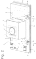
- numeral 1 generally designates a fume extractor hood of the present invention.
- the hood 1 is particularly of the type designed to at least partially fit in a receptacle 100 formed in a ceiling 101.
- the ceiling 101 has an outer surface 101a and an inner surface 101b opposite to the outer surface 101a.
- the receptacle 100 is at least partially defined by the inner surface 101b.
- the outer surface 101a is the surface of the ceiling 100 that is exposed to the view of people underneath, regardless of whether the ceiling 101 is located indoors, within a building, or outdoors, such as in a porch.
- the inner surface 101b is the surface that is generally hidden to people below the ceiling 101.
- the term "ceiling” is intended to designate any surface defining the top of a room or environment. Therefore, this term also encompasses other architectural or furnishing elements such as false ceilings or furniture that possibly locally define the top of the environment in which they are located.
- the hood 1 comprises a frame 2.
- the frame 2 is designed to at least partially fit in the receptacle 100 formed in the ceiling 101.
- the frame has at least one pair of opposite sides 3a, 3b. All the sides 3a, 3b of the frame 2 define an outer perimeter of the frame 2.
- the frame 2 has a rectangular perimeter, and comprises two pairs of opposite sides 3a, 3b. A first pair of opposite sides 3a is defined by the two long sides 3a of the frame, and a second pair of sides 3b is defined by the two short sides 3b.
- each long side 3a is contiguous to the two short sides 3b and is opposite the other long side 3a.
- each short side 3b is contiguous to the two long sides 3a and is opposite the other short side 3b.
- the frame 2 has a center axis "V", which extends substantially perpendicular to the sides 3a, 3b. In operation, the center axis "V" extends in a vertical direction.
- the frame 2 may have a perimeter having a shape other than a rectangle.
- the above indications concerning the rectangular frame 2 apply to the sides 3a and 3b, but the sides 3a, 3b will be identified differently.
- the sides 3a, 3b will be defined by arcs of a circle.
- the frame 2 further comprises a base 4 which, in operation, is placed below and projects out of the ceiling 101.
- the base 4 has an outer surface 4a that is designed to be visible by people underneath the hood 1.
- the base 4 further has an inner surface 4b, opposite to the outer surface 4a which, in operation, is hidden to people underneath the hood 1.
- the frame 2 has a suction opening 5 at the base 4, particularly at the outer surface 4a.
- the opening 5 generally faces a cooktop (not shown), which is designed to draw in the fumes generated during operation of such cooktop to cook food.
- the hood 1 further has a suction duct 6, through which the fumes extracted through the opening are channeled by the hood 1.
- the frame 2 further at least partially defines the duct 6.
- the duct 6 of the hood 1 may extend in the vertical direction identified by the center axis "V" of the frame 2.
- the frame 2 has at least one housing (not shown) for a filter.
- the hood 1 generally comprises at least one first housing for a grease filter and at least one second housing for an odor filter. Since the fumes extracted through the opening 5 are channeled through the housings to be filtered, these housings are deemed to be part of the suction duct 6.
- the hood 1 may comprise a cover element 16 which is associated with the suction opening 5 to at least partially close it.
- the cover element 16 may be embodied by a panel 17 that partially lies on the opening 5. This panel is spaced apart from the frame 2, to thereby leave one or more free peripheral slits 18, allowing fume extraction and minimizing the aesthetic impact of the hood 1.
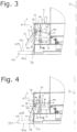
- the hood 1 comprises at least one lock member 9, which has the purpose to hold the frame 2 in the receptacle 100 of the ceiling 101, by particularly resting on the aforementioned inner surface 101b.
- This lock member 9 is placed at one of the aforementioned sides 3a, 3b of the frame 2.
- the hood 1 comprises a plurality of such lock members 9, which are placed on two opposite sides 3a, 3b of the frame 2.
- the hood 1 comprises four lock members 9, evenly arranged on the long sides 3a of the frame 2.
- each lock member 9 comprises a support 12 attached to the frame 2.
- This support 12 extends away from the inner surface 4b of the base 4, substantially at the side 3a, 3b of the frame 2 on which the respective lock member 9 is mounted. It shall be noted that the support 12 is located entirely inside the outer perimeter of the frame 2.
- each lock member 9 comprises a deployable portion 10.
- Such deployable portion 10 has a direction of deployment "D" perpendicular to the side 3a, 3b with the respective lock member 9.
- the direction of deployment "D” is also perpendicular to the center axis "V" of the frame 2.
- the deployable portion 10 is designed to alternate between a deployed configuration and a retracted configuration.
- the deployable portion 10 rests on the inner surface 101b of the receptacle 100, to thereby hold the frame 2 in the receptacle 100.
- the deployable portion 10 is pulled back into the outer perimeter of the frame 2. In this configuration, the frame 2 may be moved into and/or out of the receptacle 100.
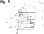
- the lock member 9 comprises a connecting portion 30.
- This connecting portion 30 has the purpose of joining the deployable portion 10 to the frame 2, in particular to the support 12 of its respective lock member 9.
- the connecting portion 30 has first 30a and second 30b opposite ends.
- the second end 30b is connected to the deployable portion 10.
- the connecting portion 30 is connected to the deployable portion 10 at a hinge axis "A".
- This hinge axis "A” is substantially perpendicular to the center axis "V” and to the direction of deployment "D".
- the first end 30a of the connecting portion 30 is rotatably attached to the frame 2, in particular to the support 12, to rotate about an additional hinge axis "K" parallel to the hinge axis "A".
- the connecting portion 30 slides along a longitudinal axis "B" substantially parallel to the center axis "V".
- the deployable portion 10 is embodied by a lug 13 that is pivotally connected to the connecting portion 30.
- the lug 13 has first 13a and second 13b opposite ends.
- the first end 13a of the lug 13 is pivotally connected to the connecting portion 30, to pivot relative to the hinge axis "A".
- the second end 13b is designed to contact the inner surface 101b of the ceiling 101.
- the lug 13 is pivoted relative to the support 12 to extend partially beyond the outer perimeter of the frame 2. This allows the second end 13b of the lug 13 to rest on the aforementioned inner surface 101b of the ceiling 101.
- the lug 13 is moved toward the support 12 by pivoting relative to the hinge axis "A".
- the lug 13 entirely fits into the perimeter of the frame 2.
- the lock member 9 comprises at least one elastic element 11 associated with the deployable portion 10 to bias the latter from the retracted configuration to the deployed configuration. More in detail, the elastic element 11 is operable between the connecting portion 30 and the deployable portion 10 to open them apart.
- the elastic element 11 is embodied by a torsion spring 14 disposed between the lug 13 and the connecting portion 30, particularly at the hinge axis "A".
- the lock member 9 comprises a grip element 15.
- This grip element 15 is connected to connecting portion 10 between the ends 30a, 30b.
- the grip element 15 also identifies the aforementioned longitudinal axis "B".
- the grip element 15 is connected to the deployable portion 10 and is placed in a position that allows access thereto when the frame 2 fits in the receptacle 100.
- the grip element15 may be actuated to pull the deployable portion from the deployed configuration back to the retracted configuration.
- the grip element 15 shall be deemed to be accessible if its use requires at most removal of parts of the hood 1, such as the cover element 16, which can be easily removed as part of ordinary maintenance and, in particular, with the frame 2 fitting in the receptacle 101.
- the grip element 15 has at least one portion placed in front of the frame 2 and particularly of all the components of the hood 1 which can be only disconnected from the frame 2 when the latter does not fit in the its receptacle 100 in the ceiling 101. Further details about the grip element 15 will be provided hereinbelow.
- the lock member 9 comprises a pin 32 that is pivotally connected to the connecting portion 30 between the ends 30a, 30b.
- the pin 32 is designed to pivot about an axis of rotation "P".
- the axis of rotation "P" is parallel to the hinge axes A, K about which the connecting portion 30 is hinged.
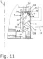
- the lock member 9 has a sleeve 25.
- This sleeve 25 is rigidly joined to the connecting portion 30 and is configured to translate along the grip element 15.
- this screw 33 is rigidly joined to the support 12 of the lock member 9, to be screwed in and out of the support 12.
- the screw 33 is oriented parallel to the center axis "V" and hence in a vertical direction.
- the axis of rotation of the screw 33 defines the aforementioned longitudinal main axis of extension "B".
- the screw 33 can be also screwed in and out of the pin 32 to move the pin 32 along the center axis "V".
- the screw 33 By screwing the screw 33 in and out, the user will be able to act on the lock member 9 from outside the frame 2.
- the user by varying the position of the pin 32 along the center axis "V", the user will be able to pivot the connecting portion 30 relative to the frame 2.
- the screw 33 may also be screwed in the sleeve 25 to move the latter along the longitudinal axis "B".
- the sleeve 25 has a threaded inner surface 25a.
- the lock member 9 has a projection 31, which is adapted to push the deployable portion 10 toward the interior of the frame 2, thereby causing it to alternate from the deployed configuration to the retracted configuration. More in detail, the projection 31 is placed on the deployable portion 10, opposite to the connecting portion 30, and protrudes outside of the frame 2. In particular, the projection 31 is formed proximate to the connecting portion 30, and is more particularly placed substantially level with the first end 13a of the lug 13.
- the support 12 In order to interact with the projection 31, the support 12 has an abutment zone 34. Such abutment zone 34 faces the projection 31, such that the projection 31 will abut the abutment zone 34 to push the deployable portion 10 into the retracted configuration.
- the above described projection 31 is omitted. Therefore, the abutment zone 34 directly faces the deployable portion 10. As the deployable portion 10 rises, it directly abuts the abutment portion 34, to be pushed by the latter into the retracted configuration.
- the deployable portions 10 are pushed into the retracted configuration but once the lock members 9 extend past the inner surface 101b, they are pushed into the deployed configuration by the elastic elements 11.
- each lock member 9 In order to pull the hood 1 out, the user disengages each lock member 9 by acting on its respective screw 33.
- the pin 32 In particular, in the first embodiment, the pin 32 is pushed upwards by screwing the screw out. As a result, the connecting portion 30 will be pivoted upwards, and the projection 31 will be moved to contact with the abutment zone 34. By further moving the pin 32 upwards, the abutment zone 34 will push the protrusion 31 to thereby impart an inward pivotal motion to the deployable portion 10, in particular against the elastic action of the elastic element 11. Then, the deployable portion 10 will be returned into the retracted configuration, which will cease the action of the lock member 9.
- the user action on the screw 33 will cause the connecting portion 30 to translate upwards along the longitudinal axis "B". Then, the deployable portion 10 will move with the connecting portion 30, until it contacts the abutment zone 34 as shown, for example, in Figure 7 . As the screw 33 is further screwed in the sleeve 25, the connecting portion 30 will further translate upwards. Then, the abutment zone 34 will push the deployable portion 10 into the retracted configuration, as shown for example in Figure 11 .
Landscapes
- Engineering & Computer Science (AREA)
- Chemical & Material Sciences (AREA)
- Combustion & Propulsion (AREA)
- Mechanical Engineering (AREA)
- General Engineering & Computer Science (AREA)
- Ventilation (AREA)
Claims (12)
- Dunstabzugshaube (1) des Typs, der zumindest teilweise in eine Aufnahme (100) passen kann, die in einer Decke (101) gebildet ist, wobei die Decke (101) eine Außenfläche (101a) und eine Innenfläche (101b) aufweist, wobei Letztere die Aufnahme (100) zumindest teilweise definiert und der Außenfläche (101a) entgegengesetzt ist, wobei die Haube (1) Folgendes umfasst:- einen Rahmen (2), der mindestens ein Paar entgegengesetzter Seiten (3a, 3b) aufweist, wobei der Rahmen (2) dazu konfiguriert ist, mindestens teilweise in die Aufnahme (100) zu passen, wobei der Rahmen (2) eine Mittelachse (V) senkrecht zu den Seiten (3a, 3b) aufweist;- mindestens ein Verriegelungselement (9), das an einer der Seiten (3a, 3b) des Rahmens (2) positioniert ist, wobei das Verriegelungselement (9) einen ausfahrbaren Abschnitt (10) umfasst, der eine Ausfahrrichtung (D) senkrecht zu seiner jeweiligen Seite (3a, 3b) des Rahmens (2) und zu der Mittelachse (V) aufweist, und zwischen einer ausgefahrenen Konfiguration, in der es auf der Innenfläche (101b) ruht, um den Rahmen in die Aufnahme (100) zu halten, und einer eingefahrenen Konfiguration, in der es innerhalb eines Umfangs des Rahmens (2) zurückgezogen ist, um zu erlauben, dass der Rahmen (2) in die Aufnahme (100) eingeführt und daraus entfernt wird, umschaltbar ist, wobei das Verriegelungselement (9) mindestens ein elastisches Element (11) umfasst, das dem ausfahrbaren Abschnitt (10) zugeordnet ist, um ihn aus der eingefahrenen in die ausgefahrene Konfiguration zu schieben;wobei das Verriegelungselement (9) ein Griffelement (15) umfasst, das mit dem ausfahrbaren Abschnitt (10) verbunden und so eingerichtet ist, dass darauf zugegriffen wird, wenn der Rahmen (2) in die Aufnahme (100) passt, wobei das Griffelement (15) entlang der Mittelachse (V) bewegbar und/oder um eine Haupterstreckungslängsachse im Wesentlichen parallel zu der Mittelachse (V) drehbar ist, um den ausfahrbaren Abschnitt (10) aus der ausgefahrenen in die eingefahrene Konfiguration zurückzuführen; dadurch gekennzeichnet, dass das Verriegelungselement (9) einen Verbindungsabschnitt (30) umfasst, der ein erstes Ende (30a) und ein zweites Ende (30b), die einander entgegengesetzt sind, aufweist, wobei das zweite Ende (30b) mit dem ausfahrbaren Abschnitt (10) verbunden ist, wobei das Griffelement (15) zwischen den Enden (30a, 30b) mit dem Verbindungsabschnitt (10) verbunden ist, wobei der Verbindungsabschnitt (30) an dem ausfahrbaren Abschnitt (10) an einer Gelenkachse (A) angelenkt ist, die im Wesentlichen senkrecht zu der Mittelachse (V) und der Ausfahrrichtung (D) ist; wobei das elastische Element (11) zwischen dem Verbindungsabschnitt (30) und dem ausfahrbaren Abschnitt (10) betätigbar ist, um sie auseinander zu öffnen.
- Haube (1) nach dem vorstehenden Anspruch, dadurch gekennzeichnet, dass der Verbindungsabschnitt (30) entlang der Längsachse (B) gleitet.
- Haube (1) nach einem der vorstehenden Ansprüche, dadurch gekennzeichnet, dass das Verriegelungselement (9) eine Hülse (25) umfasst, die fest mit dem Verbindungsabschnitt (30) verbunden ist und dazu konfiguriert ist, entlang des Griffelements (15) verschoben zu werden.
- Haube (1) nach dem vorstehenden Anspruch, dadurch gekennzeichnet, dass das Griffelement (15) eine Schraube (33) umfasst, die in die Hülse (25) geschraubt werden kann, um sie entlang der Längserstreckungsachse (B) zu bewegen.
- Haube (1) nach einem der vorstehenden Ansprüche, dadurch gekennzeichnet, dass das Verriegelungselement (9) eine Anschlagzone (34) aufweist, die dem ausfahrbaren Abschnitt (10) zugewandt ist und dazu konfiguriert ist, an dem ausfahrbaren Abschnitt (10) anzuschlagen, um ihn in die eingefahrene Konfiguration zu drücken.
- Haube (1) nach Anspruch 1, dadurch gekennzeichnet, dass das erste Ende (30a) des Verbindungsabschnitts (30) schwenkbar an dem Rahmen (2) befestigt ist.
- Haube (1) nach dem vorstehenden Anspruch, dadurch gekennzeichnet, dass das Verriegelungselement (9) einen Träger (12) umfasst, der an dem Rahmen (2) angebracht ist, wobei das erste Ende (30a) des Verbindungsabschnitts (30) an dem Träger (9) angelenkt ist, um eine zusätzliche Gelenkachse (K) parallel zu der Gelenkachse (A) zu schwenken.
- Haube (1) nach dem vorstehenden Anspruch, dadurch gekennzeichnet, dass das Verriegelungselement (9) einen Vorsprung (31) aufweist, der aus dem ausfahrbaren Abschnitt (10) zu der Außenseite des Rahmens (2) und dem Verbindungsabschnitt (30) entgegengesetzt vorsteht, wobei der Träger (12) eine Anschlagzone (34) aufweist, die dem Vorsprung (31) zugewandt ist, wobei der Vorsprung (31) dazu angepasst ist, an die Anschlagzone (34) anzuschlagen, um den ausfahrbaren Abschnitt (10) in die eingefahrene Konfiguration zu drücken.
- Haube (1) nach dem vorstehenden Anspruch, dadurch gekennzeichnet, dass der Vorsprung neben dem Verbindungsabschnitt (30) liegt.
- Haube (1) nach einem der Ansprüche 6 bis 9, dadurch gekennzeichnet, dass das Verriegelungselement (9) einen Stift (32) umfasst, der schwenkbar mit dem Verbindungsabschnitt (30) zwischen den Enden (30a, 30b) verbunden ist, wobei das Griffelement (15) eine Schraube (33) umfasst, die in den Stift (32) geschraubt werden kann, um den Stift entlang der Mittelachse (V) zu bewegen.
- Haube (1) nach einem der vorstehenden Ansprüche, dadurch gekennzeichnet, dass sie eine Vielzahl der Verriegelungselemente (9) umfasst, die sich auf beiden gegenüberliegenden Seiten (3a) des Rahmens (2) befinden.
- Haube (1) nach einem der vorstehenden Ansprüche, dadurch gekennzeichnet, dass sie zwei der Verriegelungselemente (9) umfasst, die sich auf der gleichen Seite (3a) des Rahmens (2) befinden.
Applications Claiming Priority (2)
| Application Number | Priority Date | Filing Date | Title |
|---|---|---|---|
| IT201800009820 | 2018-10-26 | ||
| PCT/IB2019/058601 WO2020084369A1 (en) | 2018-10-26 | 2019-10-09 | Hood for extracting fumes |
Publications (3)
| Publication Number | Publication Date |
|---|---|
| EP3870902A1 EP3870902A1 (de) | 2021-09-01 |
| EP3870902C0 EP3870902C0 (de) | 2024-11-27 |
| EP3870902B1 true EP3870902B1 (de) | 2024-11-27 |
Family
ID=65244513
Family Applications (1)
| Application Number | Title | Priority Date | Filing Date |
|---|---|---|---|
| EP19795656.8A Active EP3870902B1 (de) | 2018-10-26 | 2019-10-09 | Dunstabzugshaube |
Country Status (6)
| Country | Link |
|---|---|
| US (1) | US20210381696A1 (de) |
| EP (1) | EP3870902B1 (de) |
| AU (1) | AU2019369202B2 (de) |
| CA (1) | CA3114590A1 (de) |
| ES (1) | ES3013921T3 (de) |
| WO (1) | WO2020084369A1 (de) |
Families Citing this family (2)
| Publication number | Priority date | Publication date | Assignee | Title |
|---|---|---|---|---|
| CN112344407B (zh) * | 2020-10-16 | 2022-01-21 | 宁波方太厨具有限公司 | 一种装饰罩安装装置及应用有该安装装置的吸油烟机 |
| TW202426828A (zh) * | 2022-12-19 | 2024-07-01 | 藍天廚飾股份有限公司 | 分離式排油煙機 |
Citations (1)
| Publication number | Priority date | Publication date | Assignee | Title |
|---|---|---|---|---|
| EP0490074B1 (de) * | 1990-12-14 | 1997-02-12 | Bosch-Siemens HausgerÀ¤te GmbH | Einbau-Dunstabzugshaube |
Family Cites Families (11)
| Publication number | Priority date | Publication date | Assignee | Title |
|---|---|---|---|---|
| US2973177A (en) * | 1960-01-14 | 1961-02-28 | Pittsburgh Reflector Company | Troffer side support |
| US5077650A (en) * | 1990-10-31 | 1991-12-31 | Frank Cestari | Mounting system for recessed lighting fixtures |
| US6132069A (en) * | 1996-07-19 | 2000-10-17 | Moriyama Sangyo Kabushiki Kaisha | Light body, light body mounting base and embedded lighting equipment |
| GB0415965D0 (en) * | 2004-07-16 | 2004-08-18 | Audio Partnership Plc | Releasable mounting apparatus |
| DE102009057443A1 (de) * | 2009-12-08 | 2011-06-09 | Traxon Technologies Ltd. | Einbauleuchte und Anordnung mit einer Einbauleuchte |
| CN203364221U (zh) * | 2013-08-02 | 2013-12-25 | 广东奥特龙电器制造有限公司 | 一种嵌入式抽油烟机 |
| DE102014205901B4 (de) * | 2014-03-28 | 2019-05-23 | H4X E.U. | Leuchte |
| DE102014117377B4 (de) * | 2014-11-27 | 2021-04-22 | Miele & Cie. Kg | Dunstabzugshaube und Verfahren zum Befestigen |
| US9913013B1 (en) * | 2016-10-24 | 2018-03-06 | Bose Corporation | Device for installation and removal of a ceiling speaker system |
| DE102018203738A1 (de) * | 2018-03-13 | 2019-09-19 | BSH Hausgeräte GmbH | Befestigungsvorrichtung für eine Lüftungsvorrichtung und Lüftungsvorrichtung |
| EP3553387B1 (de) * | 2018-04-11 | 2020-07-08 | ELICA S.p.A. | Dunstabzugshaube |
-
2019
- 2019-10-09 EP EP19795656.8A patent/EP3870902B1/de active Active
- 2019-10-09 WO PCT/IB2019/058601 patent/WO2020084369A1/en not_active Ceased
- 2019-10-09 ES ES19795656T patent/ES3013921T3/es active Active
- 2019-10-09 US US17/288,449 patent/US20210381696A1/en not_active Abandoned
- 2019-10-09 AU AU2019369202A patent/AU2019369202B2/en active Active
- 2019-10-09 CA CA3114590A patent/CA3114590A1/en active Pending
Patent Citations (1)
| Publication number | Priority date | Publication date | Assignee | Title |
|---|---|---|---|---|
| EP0490074B1 (de) * | 1990-12-14 | 1997-02-12 | Bosch-Siemens HausgerÀ¤te GmbH | Einbau-Dunstabzugshaube |
Also Published As
| Publication number | Publication date |
|---|---|
| ES3013921T3 (en) | 2025-04-15 |
| EP3870902C0 (de) | 2024-11-27 |
| US20210381696A1 (en) | 2021-12-09 |
| CA3114590A1 (en) | 2020-04-30 |
| WO2020084369A1 (en) | 2020-04-30 |
| EP3870902A1 (de) | 2021-09-01 |
| AU2019369202B2 (en) | 2025-04-10 |
| AU2019369202A1 (en) | 2021-04-15 |
Similar Documents
| Publication | Publication Date | Title |
|---|---|---|
| EP1927811A1 (de) | Ausgestattetes Küchenelement mit Abzugshaube und ausklappbarem Kochbereich | |
| EP3553387B1 (de) | Dunstabzugshaube | |
| US3051160A (en) | One-piece built-in range | |
| US8915983B2 (en) | Range extractor hood | |
| US3102533A (en) | Counter-top range exhaust apparatus | |
| EP3870902B1 (de) | Dunstabzugshaube | |
| EP0914579A1 (de) | Halteeinrichtung für kochofen mit parallelen armen | |
| JP7814446B2 (ja) | キッチンユニット | |
| US7823580B2 (en) | Range hood apparatus and method | |
| US20190307246A1 (en) | Outdoor Kitchen Furniture | |
| EP1528327A2 (de) | Gargerät | |
| CN114375360A (zh) | 立式油烟机 | |
| EP3282196B1 (de) | Anordnung bestehend aus einer abzugshaube und einem wandschrank | |
| EP3299729B1 (de) | Montage haube und küchenschrank | |
| US5690848A (en) | Suction hood with integrated grill | |
| EP3557141A1 (de) | Freistehender kocher mit integriertem Absaug- und Filtersystem | |
| US3385284A (en) | Cooking appliance with adjustable control housing | |
| KR100383536B1 (ko) | 오븐 기능을 갖는 레인지 후드 | |
| EP1177842B1 (de) | Vorrichtung zum Befestigen von Dunstabzugshauben an der Decke | |
| GB2266586A (en) | Eye-level grills | |
| CN219418866U (zh) | 一种烤箱旋钮 | |
| KR200285235Y1 (ko) | 싱크대의 보조테이블 | |
| KR200227521Y1 (ko) | 오븐 기능을 갖는 레인지 후드 | |
| JPH0595334U (ja) | 厨房装置 | |
| JPH04319308A (ja) | システムキッチン |
Legal Events
| Date | Code | Title | Description |
|---|---|---|---|
| STAA | Information on the status of an ep patent application or granted ep patent |
Free format text: STATUS: UNKNOWN |
|
| STAA | Information on the status of an ep patent application or granted ep patent |
Free format text: STATUS: THE INTERNATIONAL PUBLICATION HAS BEEN MADE |
|
| PUAI | Public reference made under article 153(3) epc to a published international application that has entered the european phase |
Free format text: ORIGINAL CODE: 0009012 |
|
| STAA | Information on the status of an ep patent application or granted ep patent |
Free format text: STATUS: REQUEST FOR EXAMINATION WAS MADE |
|
| 17P | Request for examination filed |
Effective date: 20210312 |
|
| AK | Designated contracting states |
Kind code of ref document: A1 Designated state(s): AL AT BE BG CH CY CZ DE DK EE ES FI FR GB GR HR HU IE IS IT LI LT LU LV MC MK MT NL NO PL PT RO RS SE SI SK SM TR |
|
| DAV | Request for validation of the european patent (deleted) | ||
| DAX | Request for extension of the european patent (deleted) | ||
| GRAP | Despatch of communication of intention to grant a patent |
Free format text: ORIGINAL CODE: EPIDOSNIGR1 |
|
| STAA | Information on the status of an ep patent application or granted ep patent |
Free format text: STATUS: GRANT OF PATENT IS INTENDED |
|
| INTG | Intention to grant announced |
Effective date: 20240605 |
|
| GRAS | Grant fee paid |
Free format text: ORIGINAL CODE: EPIDOSNIGR3 |
|
| GRAA | (expected) grant |
Free format text: ORIGINAL CODE: 0009210 |
|
| STAA | Information on the status of an ep patent application or granted ep patent |
Free format text: STATUS: THE PATENT HAS BEEN GRANTED |
|
| AK | Designated contracting states |
Kind code of ref document: B1 Designated state(s): AL AT BE BG CH CY CZ DE DK EE ES FI FR GB GR HR HU IE IS IT LI LT LU LV MC MK MT NL NO PL PT RO RS SE SI SK SM TR |
|
| REG | Reference to a national code |
Ref country code: GB Ref legal event code: FG4D |
|
| REG | Reference to a national code |
Ref country code: CH Ref legal event code: EP |
|
| REG | Reference to a national code |
Ref country code: DE Ref legal event code: R096 Ref document number: 602019062644 Country of ref document: DE |
|
| REG | Reference to a national code |
Ref country code: IE Ref legal event code: FG4D |
|
| U01 | Request for unitary effect filed |
Effective date: 20241224 |
|
| U07 | Unitary effect registered |
Designated state(s): AT BE BG DE DK EE FI FR IT LT LU LV MT NL PT RO SE SI Effective date: 20250114 |
|
| PG25 | Lapsed in a contracting state [announced via postgrant information from national office to epo] |
Ref country code: IS Free format text: LAPSE BECAUSE OF FAILURE TO SUBMIT A TRANSLATION OF THE DESCRIPTION OR TO PAY THE FEE WITHIN THE PRESCRIBED TIME-LIMIT Effective date: 20250327 Ref country code: HR Free format text: LAPSE BECAUSE OF FAILURE TO SUBMIT A TRANSLATION OF THE DESCRIPTION OR TO PAY THE FEE WITHIN THE PRESCRIBED TIME-LIMIT Effective date: 20241127 |
|
| REG | Reference to a national code |
Ref country code: ES Ref legal event code: FG2A Ref document number: 3013921 Country of ref document: ES Kind code of ref document: T3 Effective date: 20250415 |
|
| PG25 | Lapsed in a contracting state [announced via postgrant information from national office to epo] |
Ref country code: NO Free format text: LAPSE BECAUSE OF FAILURE TO SUBMIT A TRANSLATION OF THE DESCRIPTION OR TO PAY THE FEE WITHIN THE PRESCRIBED TIME-LIMIT Effective date: 20250227 |
|
| PG25 | Lapsed in a contracting state [announced via postgrant information from national office to epo] |
Ref country code: GR Free format text: LAPSE BECAUSE OF FAILURE TO SUBMIT A TRANSLATION OF THE DESCRIPTION OR TO PAY THE FEE WITHIN THE PRESCRIBED TIME-LIMIT Effective date: 20250228 |
|
| PG25 | Lapsed in a contracting state [announced via postgrant information from national office to epo] |
Ref country code: PL Free format text: LAPSE BECAUSE OF FAILURE TO SUBMIT A TRANSLATION OF THE DESCRIPTION OR TO PAY THE FEE WITHIN THE PRESCRIBED TIME-LIMIT Effective date: 20241127 |
|
| PG25 | Lapsed in a contracting state [announced via postgrant information from national office to epo] |
Ref country code: RS Free format text: LAPSE BECAUSE OF FAILURE TO SUBMIT A TRANSLATION OF THE DESCRIPTION OR TO PAY THE FEE WITHIN THE PRESCRIBED TIME-LIMIT Effective date: 20250227 |
|
| PG25 | Lapsed in a contracting state [announced via postgrant information from national office to epo] |
Ref country code: SM Free format text: LAPSE BECAUSE OF FAILURE TO SUBMIT A TRANSLATION OF THE DESCRIPTION OR TO PAY THE FEE WITHIN THE PRESCRIBED TIME-LIMIT Effective date: 20241127 |
|
| PG25 | Lapsed in a contracting state [announced via postgrant information from national office to epo] |
Ref country code: SK Free format text: LAPSE BECAUSE OF FAILURE TO SUBMIT A TRANSLATION OF THE DESCRIPTION OR TO PAY THE FEE WITHIN THE PRESCRIBED TIME-LIMIT Effective date: 20241127 |
|
| PG25 | Lapsed in a contracting state [announced via postgrant information from national office to epo] |
Ref country code: CZ Free format text: LAPSE BECAUSE OF FAILURE TO SUBMIT A TRANSLATION OF THE DESCRIPTION OR TO PAY THE FEE WITHIN THE PRESCRIBED TIME-LIMIT Effective date: 20241127 |
|
| PLBE | No opposition filed within time limit |
Free format text: ORIGINAL CODE: 0009261 |
|
| STAA | Information on the status of an ep patent application or granted ep patent |
Free format text: STATUS: NO OPPOSITION FILED WITHIN TIME LIMIT |
|
| 26N | No opposition filed |
Effective date: 20250828 |
|
| U20 | Renewal fee for the european patent with unitary effect paid |
Year of fee payment: 7 Effective date: 20251016 |
|
| PGFP | Annual fee paid to national office [announced via postgrant information from national office to epo] |
Ref country code: GB Payment date: 20251022 Year of fee payment: 7 |
|
| PGFP | Annual fee paid to national office [announced via postgrant information from national office to epo] |
Ref country code: ES Payment date: 20251216 Year of fee payment: 7 |